

Page 1
OWNER’S MANUAL DMM 4650
Description
The DMM 4650 is a signal processor which allows for an universal generation and control of audio signals.
Its main purpose is the installation in electro-acoustic rack systems, but stand-alone applications are
possible as well. The audio signals can consist of alarm, gong, voice messages but also of random
combinations of these sources. The programs were created by Dynacord (preset). Anyway, it is possible
for the user (consulting company, etc.) to modify those programs and store them as user-programs. The
audio input can be mixed with the DMM 4650 internally generated audio signals (e.g. gong signals with
announcements), or given out as priority at the audio output (programmable).
The audio quality of the messages can be selected, depending on memory extension and different user
requirements. With maximum memory extension, a total recording time of 16 minutes is possible.
Password protection for various operation levels is provided. For “EASY-USER”, the provided operation
features are similar to those known from cassette recorders or CD players. The control of the programs
is performed via floating inputs and floating outputs provide status messages. The priorities and functions
of these lines can be programmed individually (Setup). A computer interface facilitates saving and loading
of the unit’s configuration and its message data.
In order to ensure functional reliability, self-surveillance and audio data verification are employed. The
alarm is ignited via internal fault-output while all warnings are logged. The DMM 4650 is maintenance-free
since no serviceable parts, batteries or accumulators are to be found inside the appliance.
Page 2

CONTENTS
INSTALLATION INSTRUCTIONS . . . . . . . . . . . . . . . . . . . . . . . . . . . . . . . . . . . . . . . . . 5
FRONT PANEL . . . . . . . . . . . . . . . . . . . . . . . . . . . . . . . . . . . . . . . . . . . . . . . . . . . . . . . 6
REAR PANEL. . . . . . . . . . . . . . . . . . . . . . . . . . . . . . . . . . . . . . . . . . . . . . . . . . . . . . . . . 7
USE OF THE DMM 4650. . . . . . . . . . . . . . . . . . . . . . . . . . . . . . . . . . . . . . . . . . . . . . . . 8
Audio functions. . . . . . . . . . . . . . . . . . . . . . . . . . . . . . . . . . . . . . . . . . . . . . . . . . 8
Control functions. . . . . . . . . . . . . . . . . . . . . . . . . . . . . . . . . . . . . . . . . . . . . . . . . 8
Sequence functions . . . . . . . . . . . . . . . . . . . . . . . . . . . . . . . . . . . . . . . . . . . . . . 9
OPERATION OF THE DMM 4650. . . . . . . . . . . . . . . . . . . . . . . . . . . . . . . . . . . . . . . . . 10
General. . . . . . . . . . . . . . . . . . . . . . . . . . . . . . . . . . . . . . . . . . . . . . . . . . . . . . . . 10
Stand-by mode . . . . . . . . . . . . . . . . . . . . . . . . . . . . . . . . . . . . . . . . . . . . . . . . . . 10
Password, user password . . . . . . . . . . . . . . . . . . . . . . . . . . . . . . . . . . . . . . . . . 10
Password, entry, operation end . . . . . . . . . . . . . . . . . . . . . . . . . . . . . . . . . . . . . 10
Priority function. . . . . . . . . . . . . . . . . . . . . . . . . . . . . . . . . . . . . . . . . . . . . . . . . . 10
Menu structure . . . . . . . . . . . . . . . . . . . . . . . . . . . . . . . . . . . . . . . . . . . . . . . . . . 11
Operation menu diagram . . . . . . . . . . . . . . . . . . . . . . . . . . . . . . . . . . . . . . . . . . 11
MESSAGE . . . . . . . . . . . . . . . . . . . . . . . . . . . . . . . . . . . . . . . . . . . . . . . . . . . . . . . . . . . 12
General. . . . . . . . . . . . . . . . . . . . . . . . . . . . . . . . . . . . . . . . . . . . . . . . . . . . . . . . 12
Message number, preset . . . . . . . . . . . . . . . . . . . . . . . . . . . . . . . . . . . . . . . . . . 12
Operation menu message . . . . . . . . . . . . . . . . . . . . . . . . . . . . . . . . . . . . . . . . . 12
Soft key “edt” . . . . . . . . . . . . . . . . . . . . . . . . . . . . . . . . . . . . . . . . . . . . . . . . . . . 13
Title . . . . . . . . . . . . . . . . . . . . . . . . . . . . . . . . . . . . . . . . . . . . . . . . . . . . . . . . 13
Priority. . . . . . . . . . . . . . . . . . . . . . . . . . . . . . . . . . . . . . . . . . . . . . . . . . . . . . 13
Play all. . . . . . . . . . . . . . . . . . . . . . . . . . . . . . . . . . . . . . . . . . . . . . . . . . . . . . 13
Release. . . . . . . . . . . . . . . . . . . . . . . . . . . . . . . . . . . . . . . . . . . . . . . . . . . . . 13
Free space . . . . . . . . . . . . . . . . . . . . . . . . . . . . . . . . . . . . . . . . . . . . . . . . . . 13
Info . . . . . . . . . . . . . . . . . . . . . . . . . . . . . . . . . . . . . . . . . . . . . . . . . . . . . . . . 13
Checksum. . . . . . . . . . . . . . . . . . . . . . . . . . . . . . . . . . . . . . . . . . . . . . . . . . . 13
Delete . . . . . . . . . . . . . . . . . . . . . . . . . . . . . . . . . . . . . . . . . . . . . . . . . . . . . . 13
Level adjustment, record level . . . . . . . . . . . . . . . . . . . . . . . . . . . . . . . . . . . . . . 14
Remote recording. . . . . . . . . . . . . . . . . . . . . . . . . . . . . . . . . . . . . . . . . . . . . . . . 14
Audio quality, recording time . . . . . . . . . . . . . . . . . . . . . . . . . . . . . . . . . . . . . . . 14
Message memory extension. . . . . . . . . . . . . . . . . . . . . . . . . . . . . . . . . . . . . . . . 14
Asterisk (*) after displayed running time. . . . . . . . . . . . . . . . . . . . . . . . . . . . . . . 14
GONG. . . . . . . . . . . . . . . . . . . . . . . . . . . . . . . . . . . . . . . . . . . . . . . . . . . . . . . . . . . . . . . 15
General. . . . . . . . . . . . . . . . . . . . . . . . . . . . . . . . . . . . . . . . . . . . . . . . . . . . . . . . 15
Gong presets . . . . . . . . . . . . . . . . . . . . . . . . . . . . . . . . . . . . . . . . . . . . . . . . . . . 15
Operation menu gong. . . . . . . . . . . . . . . . . . . . . . . . . . . . . . . . . . . . . . . . . . . . . 15
Load . . . . . . . . . . . . . . . . . . . . . . . . . . . . . . . . . . . . . . . . . . . . . . . . . . . . . . . 15
Edit . . . . . . . . . . . . . . . . . . . . . . . . . . . . . . . . . . . . . . . . . . . . . . . . . . . . . . . . 15
Title . . . . . . . . . . . . . . . . . . . . . . . . . . . . . . . . . . . . . . . . . . . . . . . . . . . . . . . . 15
Priority. . . . . . . . . . . . . . . . . . . . . . . . . . . . . . . . . . . . . . . . . . . . . . . . . . . . . . 15
Save . . . . . . . . . . . . . . . . . . . . . . . . . . . . . . . . . . . . . . . . . . . . . . . . . . . . . . . 15
List of available gong parameters. . . . . . . . . . . . . . . . . . . . . . . . . . . . . . . . . . . . 16
ALARM. . . . . . . . . . . . . . . . . . . . . . . . . . . . . . . . . . . . . . . . . . . . . . . . . . . . . . . . . . . . . . 17
General. . . . . . . . . . . . . . . . . . . . . . . . . . . . . . . . . . . . . . . . . . . . . . . . . . . . . . . . 17
Alarm presets . . . . . . . . . . . . . . . . . . . . . . . . . . . . . . . . . . . . . . . . . . . . . . . . . . . 17
Operation menu alarm . . . . . . . . . . . . . . . . . . . . . . . . . . . . . . . . . . . . . . . . . . . . 17
Load . . . . . . . . . . . . . . . . . . . . . . . . . . . . . . . . . . . . . . . . . . . . . . . . . . . . . . . 17
Edit . . . . . . . . . . . . . . . . . . . . . . . . . . . . . . . . . . . . . . . . . . . . . . . . . . . . . . . . 17
Title . . . . . . . . . . . . . . . . . . . . . . . . . . . . . . . . . . . . . . . . . . . . . . . . . . . . . . . . 17
Priority. . . . . . . . . . . . . . . . . . . . . . . . . . . . . . . . . . . . . . . . . . . . . . . . . . . . . . 17
Save . . . . . . . . . . . . . . . . . . . . . . . . . . . . . . . . . . . . . . . . . . . . . . . . . . . . . . . 17
List of available alarm parameters . . . . . . . . . . . . . . . . . . . . . . . . . . . . . . . . . . . 18
ANNOUNCEMENT . . . . . . . . . . . . . . . . . . . . . . . . . . . . . . . . . . . . . . . . . . . . . . . . . . . . 20
General. . . . . . . . . . . . . . . . . . . . . . . . . . . . . . . . . . . . . . . . . . . . . . . . . . . . . . . . 20
Operation menu announcement. . . . . . . . . . . . . . . . . . . . . . . . . . . . . . . . . . . . . 20
2
Page 3

TRIGGER. . . . . . . . . . . . . . . . . . . . . . . . . . . . . . . . . . . . . . . . . . . . . . . . . . . . . . . . . . . . 21
General. . . . . . . . . . . . . . . . . . . . . . . . . . . . . . . . . . . . . . . . . . . . . . . . . . . . . . . . 21
Operation menu trigger. . . . . . . . . . . . . . . . . . . . . . . . . . . . . . . . . . . . . . . . . . . . 21
Trigger detection. . . . . . . . . . . . . . . . . . . . . . . . . . . . . . . . . . . . . . . . . . . . . . . . . 22
Examples trigger adjustments . . . . . . . . . . . . . . . . . . . . . . . . . . . . . . . . . . . . . . 22
SEQUENCE. . . . . . . . . . . . . . . . . . . . . . . . . . . . . . . . . . . . . . . . . . . . . . . . . . . . . . . . . . 23
General. . . . . . . . . . . . . . . . . . . . . . . . . . . . . . . . . . . . . . . . . . . . . . . . . . . . . . . . 23
Sequence Presets . . . . . . . . . . . . . . . . . . . . . . . . . . . . . . . . . . . . . . . . . . . . . . . 23
Operation menu sequence. . . . . . . . . . . . . . . . . . . . . . . . . . . . . . . . . . . . . . . . . 23
Load . . . . . . . . . . . . . . . . . . . . . . . . . . . . . . . . . . . . . . . . . . . . . . . . . . . . . . . 23
Priority. . . . . . . . . . . . . . . . . . . . . . . . . . . . . . . . . . . . . . . . . . . . . . . . . . . . . . 23
Stop trigger . . . . . . . . . . . . . . . . . . . . . . . . . . . . . . . . . . . . . . . . . . . . . . . . . . 23
Step list . . . . . . . . . . . . . . . . . . . . . . . . . . . . . . . . . . . . . . . . . . . . . . . . . . . . . 23
Title . . . . . . . . . . . . . . . . . . . . . . . . . . . . . . . . . . . . . . . . . . . . . . . . . . . . . . . . 24
Save . . . . . . . . . . . . . . . . . . . . . . . . . . . . . . . . . . . . . . . . . . . . . . . . . . . . . . . 24
Sequence example. . . . . . . . . . . . . . . . . . . . . . . . . . . . . . . . . . . . . . . . . . . . . . . 24
List of available step functions in a sequence . . . . . . . . . . . . . . . . . . . . . . . . . . 25
SETTINGS . . . . . . . . . . . . . . . . . . . . . . . . . . . . . . . . . . . . . . . . . . . . . . . . . . . . . . . . . . . 26
General. . . . . . . . . . . . . . . . . . . . . . . . . . . . . . . . . . . . . . . . . . . . . . . . . . . . . . . . 26
Operation menu settings . . . . . . . . . . . . . . . . . . . . . . . . . . . . . . . . . . . . . . . . . . 26
Contrast. . . . . . . . . . . . . . . . . . . . . . . . . . . . . . . . . . . . . . . . . . . . . . . . . . . . . 26
Backlight . . . . . . . . . . . . . . . . . . . . . . . . . . . . . . . . . . . . . . . . . . . . . . . . . . . . 26
Headphones . . . . . . . . . . . . . . . . . . . . . . . . . . . . . . . . . . . . . . . . . . . . . . . . . 26
Priority. . . . . . . . . . . . . . . . . . . . . . . . . . . . . . . . . . . . . . . . . . . . . . . . . . . . . . 26
Password . . . . . . . . . . . . . . . . . . . . . . . . . . . . . . . . . . . . . . . . . . . . . . . . . . . 26
Outputs . . . . . . . . . . . . . . . . . . . . . . . . . . . . . . . . . . . . . . . . . . . . . . . . . . . . . 26
Bypass . . . . . . . . . . . . . . . . . . . . . . . . . . . . . . . . . . . . . . . . . . . . . . . . . . . . . 26
Sum gain. . . . . . . . . . . . . . . . . . . . . . . . . . . . . . . . . . . . . . . . . . . . . . . . . . . . 27
Init DMM 4650. . . . . . . . . . . . . . . . . . . . . . . . . . . . . . . . . . . . . . . . . . . . . . . . 27
Format Flash. . . . . . . . . . . . . . . . . . . . . . . . . . . . . . . . . . . . . . . . . . . . . . . . . 27
Flash space. . . . . . . . . . . . . . . . . . . . . . . . . . . . . . . . . . . . . . . . . . . . . . . . . . 27
Software . . . . . . . . . . . . . . . . . . . . . . . . . . . . . . . . . . . . . . . . . . . . . . . . . . . . 27
Language . . . . . . . . . . . . . . . . . . . . . . . . . . . . . . . . . . . . . . . . . . . . . . . . . . . 27
Backup . . . . . . . . . . . . . . . . . . . . . . . . . . . . . . . . . . . . . . . . . . . . . . . . . . . . . 27
Restore . . . . . . . . . . . . . . . . . . . . . . . . . . . . . . . . . . . . . . . . . . . . . . . . . . . . . 28
RS 232 . . . . . . . . . . . . . . . . . . . . . . . . . . . . . . . . . . . . . . . . . . . . . . . . . . . . . 28
Clock . . . . . . . . . . . . . . . . . . . . . . . . . . . . . . . . . . . . . . . . . . . . . . . . . . . . . . . 28
SELF-TEST . . . . . . . . . . . . . . . . . . . . . . . . . . . . . . . . . . . . . . . . . . . . . . . . . . . . . . . . . . 29
General. . . . . . . . . . . . . . . . . . . . . . . . . . . . . . . . . . . . . . . . . . . . . . . . . . . . . . . . 29
Operation menu self-test . . . . . . . . . . . . . . . . . . . . . . . . . . . . . . . . . . . . . . . . . . 29
CONNECTIONS. . . . . . . . . . . . . . . . . . . . . . . . . . . . . . . . . . . . . . . . . . . . . . . . . . . . . . . 30
Control inputs and control outputs Port A - D. . . . . . . . . . . . . . . . . . . . . . . . . . . 30
General . . . . . . . . . . . . . . . . . . . . . . . . . . . . . . . . . . . . . . . . . . . . . . . . . . . . . 30
Control levels and currents. . . . . . . . . . . . . . . . . . . . . . . . . . . . . . . . . . . . . . . . . 30
Inputs . . . . . . . . . . . . . . . . . . . . . . . . . . . . . . . . . . . . . . . . . . . . . . . . . . . . . . 30
Outputs . . . . . . . . . . . . . . . . . . . . . . . . . . . . . . . . . . . . . . . . . . . . . . . . . . . . . 31
Installation example . . . . . . . . . . . . . . . . . . . . . . . . . . . . . . . . . . . . . . . . . . . . . . 31
Inputs . . . . . . . . . . . . . . . . . . . . . . . . . . . . . . . . . . . . . . . . . . . . . . . . . . . . . . 31
Outputs . . . . . . . . . . . . . . . . . . . . . . . . . . . . . . . . . . . . . . . . . . . . . . . . . . . . . 31
Audio inputs and outputs . . . . . . . . . . . . . . . . . . . . . . . . . . . . . . . . . . . . . . . 32
Remote, RS 232 connection, data backup. . . . . . . . . . . . . . . . . . . . . . . . . . . . . 33
General . . . . . . . . . . . . . . . . . . . . . . . . . . . . . . . . . . . . . . . . . . . . . . . . . . . . . 33
Connection REMOTE/RS 232 . . . . . . . . . . . . . . . . . . . . . . . . . . . . . . . . . . . 33
Interface settings. . . . . . . . . . . . . . . . . . . . . . . . . . . . . . . . . . . . . . . . . . . . . . 33
Backup, Restore commands, priority . . . . . . . . . . . . . . . . . . . . . . . . . . . . . . 33
List of REMOTE commands. . . . . . . . . . . . . . . . . . . . . . . . . . . . . . . . . . . . . 34
Terminal programs . . . . . . . . . . . . . . . . . . . . . . . . . . . . . . . . . . . . . . . . . . . . 34
3
Page 4

FACTORY PRESETS . . . . . . . . . . . . . . . . . . . . . . . . . . . . . . . . . . . . . . . . . . . . . . . . . . 36
Factory presets, defaults . . . . . . . . . . . . . . . . . . . . . . . . . . . . . . . . . . . . . . . . . . 36
List of trigger signals. . . . . . . . . . . . . . . . . . . . . . . . . . . . . . . . . . . . . . . . . . . . . . 36
List of factory preset sequences. . . . . . . . . . . . . . . . . . . . . . . . . . . . . . . . . . . . . 37
List of factory preset gong signals . . . . . . . . . . . . . . . . . . . . . . . . . . . . . . . . . . . 45
List of factory preset alarm signals. . . . . . . . . . . . . . . . . . . . . . . . . . . . . . . . . . . 46
APPENDIX. . . . . . . . . . . . . . . . . . . . . . . . . . . . . . . . . . . . . . . . . . . . . . . . . . . . . . . . . . . 47
Troubleshooting . . . . . . . . . . . . . . . . . . . . . . . . . . . . . . . . . . . . . . . . . . . . . . . . . 47
FAQ’s, hints . . . . . . . . . . . . . . . . . . . . . . . . . . . . . . . . . . . . . . . . . . . . . . . . . . . . 48
Examples for alarm texts . . . . . . . . . . . . . . . . . . . . . . . . . . . . . . . . . . . . . . . . . . 50
Block diagram. . . . . . . . . . . . . . . . . . . . . . . . . . . . . . . . . . . . . . . . . . . . . . . . . . . 51
Dimensions. . . . . . . . . . . . . . . . . . . . . . . . . . . . . . . . . . . . . . . . . . . . . . . . . . . . . 52
Specifications . . . . . . . . . . . . . . . . . . . . . . . . . . . . . . . . . . . . . . . . . . . . . . . . . . . 53
Warranty . . . . . . . . . . . . . . . . . . . . . . . . . . . . . . . . . . . . . . . . . . . . . . . . . . . . . . . 54
4
Page 5

Installation instructions
The appliance has to be protected against:
- drip or splash water
- direct sunlight
- high ambient temperature or direct influence of heat sources
- high humidity
- heavy dust deposits
- extreme vibrations
In case the appliance is transported directly from a cold environment to a warm location, dampness can
precipitate on the inner parts. Operating the device is only admissible after waiting for approximately one
hour until the aparatus has gained the ambient temperature.
Should objects or liquids get into the enclosure, disconnect the unit from the mains immediately and have
the appliance checked by a DYNACORD service center, before further use.
Do not use any sprays to clean the unit, because they could lead to severe damage and/or perhaps cause
sudden fire hazard.
5
Page 6
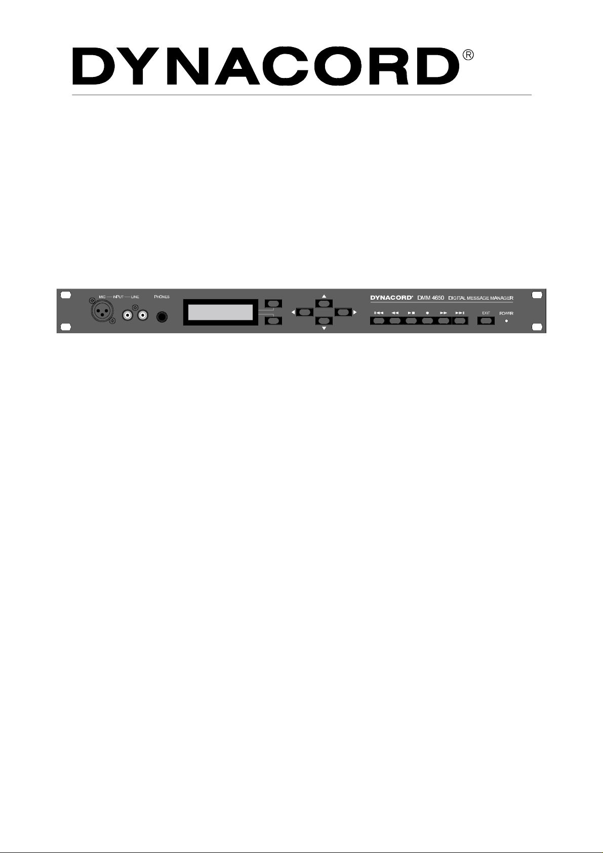
FRONT PANEL
1. INPUT MIC
XLR-socket for the connection of a microphone when
recording a message. By using a short test-sample, the
level is automatically adjusted and the setting is saved.
This input can also be used for making announcements.
2. INPUT LINE
RCA-type sockets for the connection of stereo or
monaural audio signal sources (tape deck, CD player)
when recording a message. A wired in parallel 0dBu
socket on the rear panel is also provided. By using a
short test-sample, the level is automatically adjusted
and the setting is saved.
This input can also be used for making announcements.
3. PHONES
Stereo phone jack 1/4" (6.3 mm) to pre-listen to messages, gong and alarm signals via headphones. Wired in
parallel, a 0dBu socket is provided on the rear panel.
7. RECORDER
Keys for …
TITLE skip back, REWIND, PLAY/STOP, REC, FAST
FORWARD, TITLE skip forward.
8. EXIT
Key for exiting the edit mode in order to prevent unauthorized operation. Each pressing of the key switches
back one menu stage.
9. POWER
The LED lights whenever the DMM 4650 is ready for
operation. In case the LED BLINKS you should contact
a DYNACORD service center.
4. Multi-function Display
Back-lit LC display, 2 lines with 16 characters, each.
The display lights up by pressing any key.
The display is dimmed whenever the EXIT-key gets
pressed or no key is pressed for at all within a short
while.
5. SOFT KEY
Depending on the selected operation mode, the soft
keys are used in various ways. The according function
is indicated on the display.
6. CURSOR
CURSOR-keys to control the cursor on the display and
for modifying data.
6
Page 7

REAR PANEL
1O. 24 V DC power supply
2 flat-pin plugs 1/4" (6.3 mm) for connection to emergency power supply (battery) or other external power
sources. Please mind the correct polarity (+-).
11. REMOTE
The 9-pole D-SUB connector “Remote-Control RS-232"
is a serial computer interface for data transfer and
service functions.
PORT A-D
All inputs and outputs are provided in 2-pole floating
design and isolated from the DMM 4650 circuitry and
adjacent lines.
Each input is realized as an AC opto-coupler (AC floating polarity).
Each output has a floating relay contact.
Each port connector (DB 25) has 4 inputs, 4 outputs,
and per port +24 V line and ground potential conductors.
By means of the 24 V DC voltage, it is possible to
connect external floating control keys as well as contacts directly.
12. PORT A
4 control inputs and 4 trigger outputs
1 fault output (alarm on defect of the appliance)
1 ±24V DC, 90 mA power source
13. PORT B
Control inputs, trigger outputs and ±24 V DC
14. PORT C
Control inputs, trigger outputs and ±24 V DC
* optionally retrofitted
15. PORT D
Control inputs, trigger outputs and ±24 V DC
* optionally retrofitted
16. PRE-OUT
RCA-type socket, pre-listen
All inputs and outputs and their corresponding functions
can be freely assigned or a factory preset can be
recalled instead.
17. REC-INP
RCA-type socket, recording, announcement
18. OUTPUT
3-pole XLR-type connector (audio output) electronically
balanced (transformer can be retrofitted).
19. INPUT
3-pole XLR-type connector (audio input) electronically
balanced (transformer can be retrofitted).
7
Page 8
Use of the DMM 4650
The DMM 4650 can be used in both, incorporated in a rack shelf system or as stand-alone unit. The
installer should automate the daily sequences by external control keys, sensors, contacts and the
corresponding unit settings. This applies for gongs, alarms, messages and their combinations, as well as
for recordings of variable announcements. This contributes to a considerable advantage in the ease of
use since manually operating the appliance is not necessary anymore.
Often used functions of the DMM 4650 are directly implemented as factory presets and can be utilized
without any additional programming effort. By editing the default values and storing them into a user preset
a customer-optimized configuration is quickly developed.
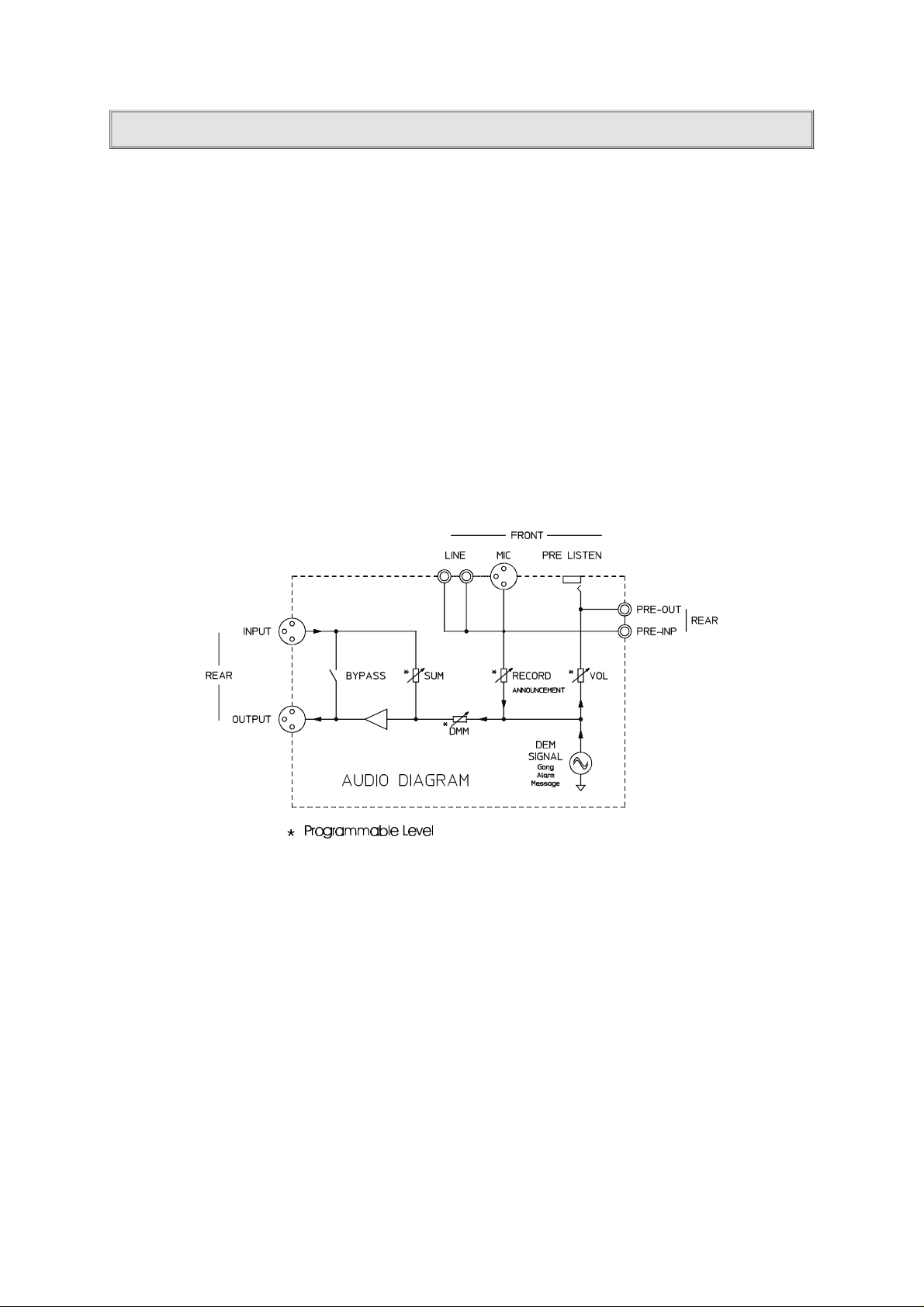
Audio function
The audio signals of the electro-acoustic sound reinforcement system are looped via INPUT and OUTPUT
to the power amplifier. The SUM control can be programmed for this stand-by position. In case of failure
a stand-by relay takes over the connection. When starting a sequence via control line, the desired audio
signal gets generated (DMM SIGNAL) and fed to the OUTPUT via the programmable DMM-control. The
controls (DMM, SUM) defined within the sequence determine, whether the two audio signals are merged
or the one gains priority over the other.
The MIC, LINE input is used for recording a message and can also be used for announcement purposes.
The headphones outputs PRE-LISTEN and PRE-OUT are for monitoring the DMM signals without actually
starting a transmission.
Control function
A maximum of 16 floating inputs are provided for integration into a sound reinforcement installation. Their
use and polarity can be freely programmed. A maximum of 16 floating relay contacts are provided to be
used as control outputs. The inputs and outputs are divided into 4 Ports (A, B, C, D,); where Port A also
contains a fault contact.
8
Page 9
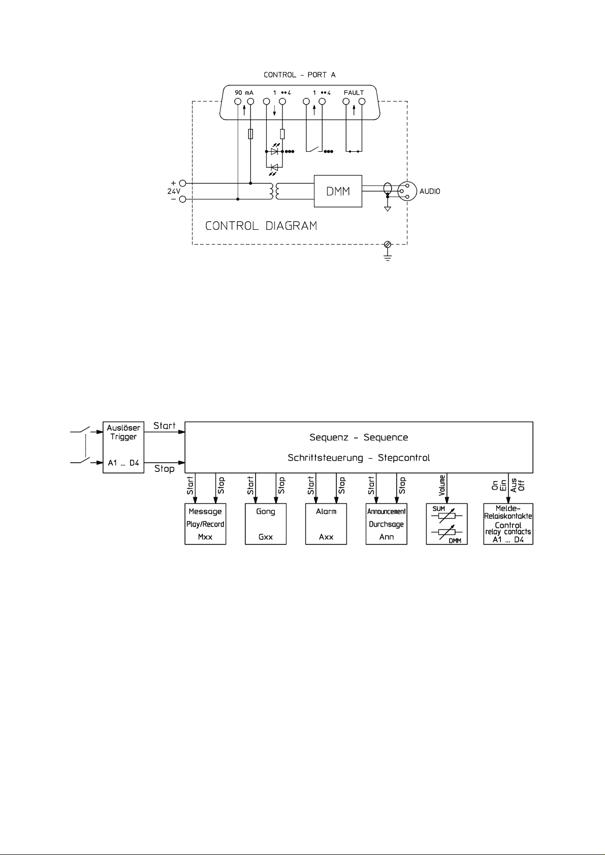
Each of the 4 ports also supplies a power source in order to facilitate the connection of floating contacts.
The ground and earthing conditions are shown in the above diagram. The strict separation of control and
audio signals guarantees the trouble-free installation.
Sequence function
The following example shows in sequence the necessary steps from closing the contact of an external
switch to listening to the audio signal:
A switch is connected to one of the DMM 4650’s control inputs (A1 - D4). The desired input is selected
in the trigger menu. Logic level (high, low), delay, and function (dyn, stc, latch) can be set. The desired
sequence (Sxx) gets chosen here as well.
For this sequence, the actions of the DMM 4650 are programmed step by step. Standard sequences are
provided as factory presets. They can be modified as need arises and stored as user presets.
Example of a sequence: set output (lamp indicator), audio control SUM off, audio control DMM -3 dB, wait
for input release, after release start alarm, delay 10 sec. (alarm duration), end.
This sequence is entered line-by-line with special commands (list page 25) and - including name and
priority - stored as a preset. If an appliance uses unaltered functions on a regular basis, it is also possible
to save these sequences via the RS 232 interface.
9
Page 10

OPERATING THE DMM 4650
General
All adjustments carried out at the appliance remain in memory even if the appliance is not connected to
a power source (EPROM).
Pressing the EXIT-key lets you step back and forth through the levels of the operation menu tree (page
11). The stand-by mode is entered by pressing the EXIT-key when in the “main menu”.
If no key is pressed within a period longer than 5 minutes, the appliance enters the stand-by mode
automatically (except during recording and restore).
Stand-by
When the DMM 4650 is connected to a power source, the green POWER-LED lights, the display is
dimmed, and the relay outputs are set to their pre-programmed states according to the system’s
configuration. This stand-by status is remained until a control input starts a sequence. The display shows
the sequence’s name and number for the duration of the sequence. After completion of the sequence,
the DMM 4650 re-enters stand-by mode.
The states of the control “outputs”, the audio relay “bypass”, and the “sum level” setting during stand-by
operation are set in the operation menu“System setup” (page 26).
Password
Password-protection prevents the DMM 4650 from unauthorized operation. Three distinct user levels are
available which can be accessed by entering the respective password. As factory defaults, “1111" is
programmed for Level 1 (easy operation), ”2222" for Level 2 and “3333" for Level 3 (installer). Individual
modification for each user is possible. The menu tree diagram (page 11) shows which access is assigned
to the respective user level.
Password entry, operation end
Pressing any key on the DMM 4650’s front panel, “Password ?” appears on the display. Using the cursor
keys you have to enter a 4-digit number and confirm it with the menu key ok. After entering the correct
4-digit password, the display shows the number of your user level. Using the cursor keys you are able to
select the desired menu. The EXIT-key cancels the operation and the appliance is protected against
unauthorized use.
Priority function
With the DMM 4650 provides the opportunity to set priorities from 0 to 99; where 99 represents the highest
priority level. Setting the priority level leads in different results.
The priority of a sequence is defined by its free programmable priority setting (menu “sequence” “priority”).
This determines, whether e.g. a fire alarm sequence cancels a gong control sequence. Not the control
line of an input, but the priority number of the triggered sequence determines its priority. With equal
priorities, the sequence that had been started first remains valid.
The selected user level states the priority for the operation on the appliance. User level 1 = priority no.
33, user level 2 = priority no. 66, and user level 3 = priority no. 99. Modifying the default for lower user
levels is performed within the menu “System setup” “priority’”. The setting of the user priority controls,
whether an operator gets interrupted by an important sequences (sequence priority).
Users are able to modify messages, gongs, and alarms and save them as user presets. Depending on
the actual user level, the programs are automatically provided with the corresponding user priority
numbers (see above). They are maintained for the case that the original preset’s priority is lower. In this
way it is guaranteed that user 1 cannot modify the presets of user 2. In order to allow access for other
users, the priority allocation can be modified downwards (lower priority) by the respective user before
storing a preset
(menu: “message > priority", gong" > “priority”, “alarm" > ”priority")
If recording a message via remote recording, the priority number of the recording sequence is transferred
to the message.
10
Page 11
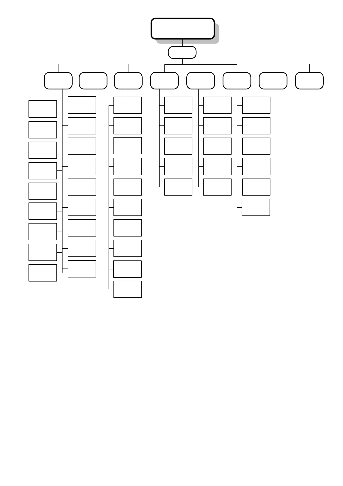
Passwort
Hauptmenue
Main-Menue
System-Setup
Helligkeit
Backlight
1
Priorität
Priority
2
Ausgänge
Outputs
3
Summenpegel
Sum-Gain
3
init DMM 4650
init DMM 4650
3
Flash Platz
flash space
1
Sprache
Language
3
Restore
Restore
3
Uhr
Clock
1
Einstellung
1
Durchsage
Announcement
Kontrast
Contrast
1
Kopfhörer
Phones
1
Passwort
Password
1
Bypass
Bypass
3
Abschwächer
Attenuator
3
format Flash
format Flash
3
Software
Software
1
Backup
Backup
2
RS232
RS232
2
Message
Message
1
1
Play/record
edit
1
Titel
title
1
Priorität
priority
1
Play alle
play all
3
freigeben
release
3
Leerblocks
free space
1
Info
info
3
bestätigen
confirm
3
Checksumme
checksum
3
löschen
delete
1
Gong
Gong
1
laden
load
1
Editor
edit
1
Titel
title
1
Priorität
priority
1
sichern
save
1
1 = Easy use = User 1
2 = Normal use = User 1 +2
3 = Special use = User 1 + 2 +3
Alarm
Alarm
1
laden
load
1
Editor
edit
1
Titel
title
1
Priorität
priority
1
sichern
savel
1
Sequenz
Sequence
2
laden
load
2
Priorität
priority
3
Stoppbedingung
stop-trigger
3
Schrittliste
step-list
2
Titel
title
2
sichern
save
3
Auslöser
Trigger
3
Selbsttest
Selftests
3
Page 12
MESSAGE
General:
Messages are audio signals, stored in the DMM 4650 as information, alarm announcements or other often
used texts. Recording a message can be performed directly at the DMM 4650 or by means of remote
recording. Playback via sum output is achieved by starting a message (Mxx) within a suitable sequence
(see “Trigger”, “Sequence”).
For test purposes the message can be listened to via the Pre-listen outputs using the recorder keys
PLAY/STOP. The functions are similar to a cassette recorder, with the difference that the audio data is
saved digitally in maintenance-free flash memories. Depending on individual needs, different audio
qualities are selectable. The maximum recording time depends on the selected audio quality and the
installed memory (see table, page 14).
A backup of all message audio data is possible through analog recording (cassette deck, DAT recorder)
or as a digital backup on a computer via the remote interface (RS 232).
Message number, Preset
Up to 100 distinct messages (M00 to M99) including title, name, and priority can be saved.
The DMM 4650 is shipped without any pre-recorded messages, since - depending on individual user
requirements and custom applications – variations would be numerous. Some factory preset sequences
use M00, M01, and M02 (see list of preset sequences). Thus, they have to be recorded for incorporating
them in the respective applications. Some text examples are to be found at the end of this manual.
Operation menu “message”
Confirming the menu selection “message” by using the soft key “ok”, the number of the message appears
in the display together with its title and playback time (hours : minutes . seconds). The DMM 4650 is now
in the recording/playback mode and can be operated using the transport-keys as follows:
Note: This mode only allows playback via the PRE-listen/Phone outputs!
Title skip backwards, selects the previous actually recorded message. During playback
the selected message starts playing immediately.
Rewind, skips back one message, during playback fast rewind enables the user to listen
to a specific part several times.
Play/Stop starts or stops the playback of the selected message. Recording is stopped by
pressing the stop key.
Recording, pressing this key once switches the selected message into recording stand-by.
In case a previously recorded message exists, the question “delete?” is displayed and
leaving you the choice to record a new message with “Y=Yes” or cancel the command
with“N=No”. If you choose delete, the record key has to be pressed again after completion
of the procedure. If this message is not supposed to be deleted, you have to select an empty
location. The items “Recording type ”and “Recording level” are explained later. The display
now shows “record Mxx” and “pause” with a bargraph, indicating the current signal level.
Pressing the record key again starts the recording and “play time” replaces “pause”.
Pressing the Stop/Play-key terminates the recording.
Fast forward, skips to the next message, forwarding during playback enables the user to
listen to parts of a longer message.
Title skip forward, selects the next actually recorded message, during playback this next
message is immediately audible.
Using the cursor keys lets you select the previous or next message number.
Soft key “vl” accesses the volume setting dialog for the phone and pre-listen outputs using
the cursor keys.
Soft key “edt” accesses the menu level for title editing, etc. (see following paragraph).
12
Page 13

Soft key “edt”
Using the “edt” key in playback mode provides the opportunity to edit and manage your message structure.
The keys are used to select the following menu items.
Title
Confirming “Title” with the soft key “ok” the selected message’s current name appears on the display.
Using the cursor keys lets you enter a name which can consist of up to 8 characters. The soft keys “A-a”
are used to toggle between between the upper and the lower letter case while “spc” inserts a blank. After
pressing “EXIT” (one menu level down) the question “store y, n” appears, in order to prevent any
inadvertent alteration of the name.
Priority
Confirming “Priority” with the soft key “ok”, the priority number of the selected message appears on the
display and, by using the cursor keys, providing the user with the possibility to alter the number from 00
up to the his/her priority level. A higher priority prevents unauthorized alteration of this preset by users
with lower priority. After pressing “EXIT” (one menu level down) you have to choose on the appearance
of the question “store y, n”, whether you want to make your changes permanent.
Play all
Confirming “Play all” with the soft key “ok”, the name of the first message gets displayed. Using the
PLAY/STOP-key lets you start or stop the playback of all recorded messages. Mostly, this menu item
serves for transferring all recorded messages onto an analog audio tape deck or DAT recorder via the
phone/pre-listen outputs.
Release
Confirming “Release” with the soft key “ok”, the display shows that the search for lost blocks in the flash
memory (sound memory) has been engaged. Whenever such blocks are found, the memory structure
gets repaired which is also indicated on the display. This menu’s operation is used to release memory
that has been mistakenly reserved.
Free space
Confirming “Free space ” with the soft key “ok”, the number of available flash memory chips and the overall
free sound memory capacity are displayed in %.
Info
Confirming “Info” with the soft key “ok”, shows the audio quality setting and the used space for the
previously selected message.
Confirm
The audio data of a message is constantly monitored. In case an inaccurate data structure (see also
self-surveillance page 29) is detected, the corresponding message is marked with an asterisk (*). Anyway,
if the erroneous data does not affect the audible result of the sound reproduction, “confirming” with the
soft key “ok” omits the marking (*). From now on, the actual data is utilized as test pattern and you are
given the possibility to acknowledge the fault indication (Power-LED blinks) within the menu “self-test”
(page 29).
Check sum
Confirming “Check sum” with the soft key “ok”, the check sum of the previously selected message appears
on the display. In case of fault, this value is used as a reference for erroneous messages.
Delete
Confirming “delete” with the soft key “ok”, shows the question “delete?” on the display. Using the soft keys
“y=yes, n=no” lets you erase the previously selected message.
13
Page 14

Recording level
An integrated, electronic control automatically adjusts the input sensitivity of the DMM 4650’s (Mic, Line,
Rec. Inp) inputs. This level setting remains unchanged, until the question “Select new recording level?”
is answered by using the soft key “y=yes” before starting a new recording. By using a short test signal
marks the new setting of the control which is automatically stored. Pressing the soft key “ok” exits the
recording level menu.
Adjusting the recording level only becomes necessary when the connected signal source is changed or
major level changes occur.
Remote recording
It is possible to activate a recording via one of the control inputs (ports A .. D). An example given in the
list of factory sequences (S29, S30) on the pages 40-41. The message defined within the sequence is
automatically erased before the new recording starts. The example employs an indication lamp for start
recording (= deleting end) and the maximum recording time is set to 10 seconds.
Adjusting the recording level corresponds to the description in the previous paragraph. The message’s
audio quality setting stays unaltered as well. The priority number of the sequence gets copied to the priority
of the message.
Audio quality, recording duration
Prior to recording a message, “recording type” is shown on the display. The cursor keys are used to alter
the audio cutoff frequency (16 kHz, 8 kHz, 4 kHz) and the signal quality (CD = 16 bit linear, long = 8 bit,
µ-Law). The factory default setting is “8 kHz long” for all messages. The newly set audio quality is
maintained and individual adjustment for each message is possible.
Table for recording time (minutes) versus audio quality and installed sound memory extension (NR 90205).
Accuracy CD long*
bandwidth 4 kHz 8 kHz 16 kHz 4 kHz 8 kHz 16 kHz
without NR 90205 2 min 1min 0,5 min 4 min 2 min 1 min
1x NR 90205 4 min 2 min 1 min 8 min 4 min 2 min
2x NR 90205 6 min 3 min 1,5 min 12 min 6 min 3 min
3x NR 90205 8 min 4 min 2 min 16 min 8 min 4 min
* The specified times for the"long" recording mode are minimum values since the active data reduction
recognizes pauses in the audio signal. Pauses are defined as passages where the signal level drops -70
dBu below full modulation.
Message memory extension
It is possible to extend the sound memory capacity of the appliance by incorporating up to three additional
plug-in boards (extension kit NR 90205). The corresponding recording times are specified in the table
above. The flash memories have to be formatted after insertion (see menu “system setup” > “format
flash”).
Asterisk (*) behind message duration
An asterisk * behind the message recording time display signals that the corresponding data has been
corupted. The error is shown by the blinking Power-LED. In case you decide that the audio quality is
sufficient, after listening to the recording, you have to enter the menu “confirming” (page 13) to delete the
*-sign. If the result is not tolerable, the only solution is re-recording the message. To omit the blinking
Power-LED you have to acknowledge error no. 14 in the “self-test” menu (page 29).
14
Page 15

GONG
General:
Gong Presets are audio signals that can be started within a sequence. Order and parameters of a gong
sequence can be edited. For test purposes the sound can be started in the “gong > editor” menu by use
of the PLAY/STOP keys. It is audible via the Pre-Listen outputs.
Gong Presets
20 freely programmable presets (user preset) are available; from G00 - G19. Starting with G20 and going
to G26 factory preset gong sequences are programmed. The corresponding functions are explained in
the table on page 45. Erasing the factory presets is not possible. Creating your own gong sequence is
easiest accomplished by modifying an existing, possibly similar gong (user or factory preset) and storing
it under a new number together with its new title and priority.
Operation menu gong
Confirming the menu selection “gong” with the soft key “ok”, the cursor keys < > allow selecting the
following sub menus.
Load
Confirming “load” with the soft key “ok”, “Gxx ‘Title ‘and the soft keys ”yes, no" appear on the display.
Using the cursor keys the gong number xx is modified while the corresponding name is being displayed.
“y” lets you load the selected gong into memory and modification is performed in the “editor” menu.
Editor
The “editor” menu allows modification of gong sequences, envelopes, repetition amounts and several
other parameters (see parameter listing). Testing the gong’s sound properties is possible by starting the
gong sequence, using the PLAY/STOP key. The audio signal is presented at the pre-listen outputs.
Parameter modifications are audible after performing a restart. Pressing the RECORD key stops the gong.
After pressing the “EXIT” key (previous menu level), the question “store yes, no?” appears on the display.
Acknowledging this question lets you save your new settings in a user preset.
Title
Confirming “Title” with the soft key “ok”, the name of the currently loaded gong sequence appears on the
display. Using the cursor keys you are able to enter a new name that consists of up to 8 characters. The
soft keys “A-a” are used to shift between the upper and the lower character case while “spc” inserts a
blank character. After pressing the “EXIT” key (previous menu level), the question “store yes, no?” appears
on the display. Acknowledging this question lets you save your new settings in a user preset.
Priority
Confirming “Priority” with the soft key “ok”, the priority number of the selected gong preset gets displayed.
Using the cursor keys, the priority number can be set starting from 00 up to the user priority. A higher
priority protects against unauthorized alteration of this preset by users with lower priority level. All factory
presets are provided with a priority of 00, because they cannot be overwritten, anyway. This offers any
user the possibility to use them as prototype sequences.
After pressing the “EXIT” key (one menu level down), the question “store yes, no?” appears on the display.
Acknowledging this question lets you save your new settings in a user preset.
Save
Confirming “save” with the soft key “ok”, the currently selected gong number gets displayed. Using the
cursor keys, the desired gong number can be entered. Storing a preset has to be confirmed with the soft
key “y = yes”. With“save” all modifications in the above mentioned menu items are saved into the selected
user preset. Thus, individually saving the parameters is not necessary, since they remain in memory until
another gong is being loaded.
15
Page 16

List of available gong parameters
Type four-stroke, three-stroke
bar1: first gong stroke, A highest sound, B, C, to D deepest sound
attack1: attack rate from 00ms (hard) to 99ms (soft)
release1: fading sound from XXL (long, several seconds.), XL, L, M, S, XS, XXS (short, approx. 1sec)
start 2: start delay of the second gong stroke in seconds. (min 00.0s, max 99.9s)
bar2: second gong stroke, A highest sound, B, C, to D deepest sound
attack2: attack rate from 00ms (hard) to 99ms (soft)
release2: fading sound from XXL (long, several seconds.), XL, L, M, S, XS, XXS (short, approx. 1sec)
start 3: start delay between second and third gong stroke in seconds. (min 00.0s, max 99.9s)
bar3: third gong stroke, A highest sound, B, C, to D deepest sound
attack3: attack rate from 00ms (hard) to 99ms (soft)
release3: fading sound from XXL (long, several seconds.), XL, L, M, S, XS, XXS (short, approx. 1sec)
start 4: start delay between third and fourth gong stroke in seconds. (min 00.0s, max 99.9s)
bar4: fourth gong stroke, A highest sound, B, C, to D deepest sound
attack4: attack rate from 00ms (hard) to 99ms (soft)
release4: fading sound from XXL (long, several seconds.), XL, L, M, S, XS, XXS (short, approx. 1sec)
Type two-stroke, one-stroke
bar1: first gong stroke, A highest sound, B, C, to D deepest sound
attack1: attack rate from 00ms (hard) to 99ms (soft)
release1: fading sound from XXL (long, several seconds.), XL, L, M, S, XS, XXS (short, approx. 1sec)
start 2: start delay of the second gong stroke in seconds. (min 00.0s, max 99.9s)
bar2: second gong stroke, A highest sound, B, C, to D deepest sound
attack2: attack rate from 00ms (hard) to 99ms (soft)
release2: fading sound from XXL (long, several seconds.), XL, L, M, S, XS, XXS (short, approx. 1sec)
repetition: number of repetitions of the gong sequence (min 1x, max 9999x), 0000 corresponds to
infinite repetition.
rep-del: time between two gong sequences in seconds (min 00.1s, max 99.9s).
Remarks regarding parameter setting:
Although the above mentioned parameters are extensively variable, the gained results not always
represent a good sound. E. g.: attacks for low frequency bar strokes are acoustically quite different from
the gong A sound.
Since a maximum of 2 gong strokes can be simultaneously processed, starting the third gong too early
will abruptly end the first one and lead to unpleasant sound cut-off knacks. Effects like these resulting
from extreme parameter settings are of physical reason and should be optimized by listening tests, first.
16
Page 17

ALARM
General:
Alarms are audio signals that can be started within a sequence. The alarms are square wave forms
providing the possibility for various parameters to be adjusted. For test purposes, it is possible to start the
alarms signals in the “alarm editor” menu using the PLAY/STOP key. They are present on the pre-listen
outputs.
Alarm Presets
20 freely programmable presets (user presets) are available; from A00 to A19. The factory presets are
pre-programmed on the preset numbers A20 - A34. The corresponding functions are explained in the
table on page 46. Erasing these presets is not possible. In order to create your own alarm preset, modifying
an existing, possibly similar alarm (user or factory preset) and storing it under a new number together with
its new title and priority, is the easiest way to accomplish this task.
Operation menu alarm
Confirming the menu selection “Alarm” with the soft key “ok” lets you select the following sub menus using
the cursor < > keys .
Load
Confirming “load” with the soft key “ok”, Axx ‘Title’ and the soft keys “yes, no” appear on the display. Using
the cursor keys lets you edit the alarm number xx while the corresponding name is displayed. “Y” loads
the selected alarm into memory while further editing is performed in the “editor” menu.
Editor
The menu “editor” allows modification of audio frequencies, envelopes, duty-factors and several other
parameters (see parameter listing). Testing the alarm’s sound properties is possible by starting the alarm
sequence using the PLAY/STOP key. The sound is presented via the pre-listen outputs. Parameter
modifications are audible after performing a restart. The RECORD-key stops the alarm.
After pressing the “EXIT” key (previous menu level), the question “store yes, no?” appears on the display.
Acknowledging this question lets you save your new settings in a user preset.
Title
Confirming “Title” with the soft key “ok”, the name of the currently loaded alarm is displayed. Using the
cursor keys lets you enter a name of up to 8 characters. The soft keys “A-a” shifts between the upper and
the lower character case while “spc” inserts a blank character.
After pressing the “EXIT” key (previous menu level), the question “store yes, no?” appears on the display.
Acknowledging this question lets you save your new settings in a user preset.
Priority
Confirming “Priority” with the soft key “ok”, the priority number of the selected alarm preset appears on
the display. Using the cursor keys, the priority number can be set starting from 00 up to the user priority.
A higher priority protects against unauthorized alteration of this preset by users with lower priority level.
All factory presets are provided with a priority of 00, because they cannot be overwritten, anyway. This
offers any user the possibility to use them as prototype sequences.
After pressing the “EXIT” key (one menu level down), the question “store yes, no?” appears on the display.
Acknowledging this question lets you save your new settings in a user preset.
Save
Confirming “save” with the soft key “ok”, the currently selected alarm number is displayed. Using the cursor
keys, you are able to enter the number of the desired alarm. Storing a preset has to be confirmed with
the soft key “y = yes”. With“save”, all modifications in the above mentioned menu items are saved into
the selected user preset. Thus, individually saving the parameters is not necessary, since they remain in
memory until another gong is being loaded.
17
Page 18

List of available alarm parameters
Type Uni-sweep
frequency1: pitch at sound-start in Hz (min 40Hz, max 9999Hz) is swept until frequency2 is reached.
frequency2: pitch at sound-stop in Hz (min 40Hz, max 9999Hz).
time: duration of the sweep - Freq1 to Freq2 - in seconds., (min 0.01s, max 99.99s).
ratio: duty-cycle of the square wave in percent, (min 1%, max 50%)
repeat: number of repetitions of the sweep Freq1. > Freq2 (min 1x, max 9999x).
0000 corresponds to infinite repetition.
Values in parenthesis ( ), example DIN alarm, A20
Type Bi-sweep
frequency1: pitch at sound-start in Hz (min 40Hz, max 9999 Hz) is swept until frequency2 is reached.
frequency2: reverse frequency of the sound in Hz (min 40Hz, max 9999Hz) is swept until frequency1
is reached.
time: sweep duration from freq1 to inversion point in sec., (min 0.01s, max 99.99s).
The duration of the sweep freq1> inversion point > freq1 is symmetrical.
ratio: duty-cycle of the square wave in percent, (min 1%, max 50%)
repeat: number of repetitions of the sweep Freq1.> inversion point (min 1x, max 9999x).
0000 corresponds to infinite repetition.
Values in parenthesis ( ), example siren, A22
Type continuous sound
frequency: pitch of the sound in Hz (min 40Hz, max 9999Hz)
ratio: duty-cycle of the square wave in percent, (min 1%, max 50%)
time: duration in sec., (min 0.01s, max 99.99s). 0.00s corresponds to infinite duration.
Values in parenthesis ( ), example BZB all clear signal, A25
18
Page 19

Type Jump sound
frequency1: pitch at sound-start in Hz (min 40Hz, max 9999Hz) jumps after time1 to frequency2
time1: duration for which freq1 is heard in sec., (min 0.01s, max 99.99s).
frequency2: pitch of the sound in Hz (min 40Hz, max 9999Hz) jumps after time2 to frequency1
time2: duration for which freq2 is heard in sec., (min 0.01s, max 99.99s).
ratio: duty-cycle of the square wave in percent, (min 1%, max 50%)
repeat: number of repetitions of one frequency (min 1x, max 9999x).
0000 corresponds to infinite repetition.
Values in parenthesis ( ), example Post, A23
Type burst
Frequency: pitch of the sound in Hz (min 40Hz, max 9999Hz)
on-time: duration for which the sound is heard in sec., (min 00.01s, max 99.99s).
off-time: duration of the pause in sec., (min 00.01s, max 99.99s).
Ratio: duty-cycle of the square wave in percent, (min. 1%, max. 50%)
repeat: number of repetitions of the sound (min 1x, max 9999x).
0000 corresponds to infinite repetition.
Values in parenthesis (), example ship2, A31
19
Page 20

Announcement
General:
Using the announcement function provides the possibility to assign incoming audio signals from the
recording inputs (Mic, line, Rec-Inp) directly to the sum output. Especially in stand-alone applications this
option is particularly useful, since it will possibly save one microphone amplifier. Starting the function is
either performed in the DMM 4650’s operation menu or remotely controlled via a control line. For external
operation a sequence is provided as factory preset S32 (page 42) which is easily adapted according to
individual requirements.
Operation menu announcement
Confirming the menu selection “announcement” with the soft key “ok”, “select new input level?” and the
soft keys “yes, no” are displayed. Adjusting the electronic input level control is performed here. After
recording a short test signal, the control’s new setting is automatically stored and stays. This value is
independent of the recording level in Massage recording. Pressing the soft key “ok” cancels the level
adjustment menu and the DMM 4650 returns into announcement mode.
The display shows the message “Announcement” and a bargraph for optical control of the correct input
level setting. The soft key “vl” allows modifying the pre-listen outputs’ volume setting while “end” closes
the announcement function.
Setting the recording level a new is required only when the connected signal source is changed or any
other large scale alterations of the input level take place.
20
Page 21

Trigger
General
The menu trigger allows to assign the connection of a control input to a function of the DMM 4650
(sequence start) while various control inputs can initiate a single sequence. The separate logic control
settings for each input provide the possibility to optimally match the requirements of an installation.
Pressing the soft key “set” stores the new trigger and it remains in memory even during periods when the
mains or battery power is missing.
The control inputs’ technical specifications are to be found in the chapter CONNECTIONS as well as in
the APPENDIX.
Operation menu trigger
Confirming the menu selection “trigger” with the soft key “ok”, using the cursor keys provides the possibility
to make the following settings:
1 Using the cursor keys selects a control input. Possible selections are the Ports A, B, C, D and their
corresponding input numbers 1, 2, 3, 4.
2 The logic control level gets also selected using the cursor keys: H=high (flowing current), L=Iow (no
current), X=H or L (variable currents) and selecting “off” switches the sequence start of the selected
line off.
3 Using the cursor keys sets a bounce time between 0.0 and 25.0 seconds. The logic control level
selected in point 2 has to be present (stable) at the control input at least for this time value, so that
the prerequisite for a sequence start is fulfilled.
4 The cursor keys provide the possibility to choose of a selection of three distinct conditions for a
sequence to be started. A valid start attempt is initiated only, if the conditions 2 and 3 are fulfilled.
The switch “dyn” = dynamic tries to start the stated sequence and simultaneously deletes the start
command. A currently running sequence with equal or higher priority prevents the sequence start
command from being initiated.
The switch “stc” = static tries to start the selected sequence as long as the conditions 2 and 3 deliver a
true result. This allows the periodic repetition of a sequence, as long as the conditions are fulfilled (e.g. a
key is kept depressed). In case a sequence with equal or higher priority is currently running, the start of
a new sequence is only possible after completion of the first sequence and, if the trigger conditions at this
moment are still fulfilled.
The switch “lat” = latched stores the start command and tries to initiate the selected sequence continuously
until its launch has been successful. A new triggering of this input is stored only after completion of the
sequence. All16 control inputs are separately stored and the sequences are launched in the succession
of their priorities.
5 The sequence which is supposed to be started with this control line can be selected with the cursor
keys.
6 Pressing the soft key “set” stores the above mentioned settings and actives them immediately.
21
Page 22

Trigger recognition
The level of the control inputs are periodically monitored by the processor. The sampling time (Ts = sample
rate) is typically T
= 30 msec. The maximum monitor interval can be set to T
s typ
= 100 msec. Thus,
s max
shorter impulses, spikes or quick AC voltages are recognized inaccurate or with a delay (undersampling).
The bi-polar control inputs evaluate both half-waves of AC voltages.
Examples for trigger settings
Ts = sample delay, T
If the control input is ON for at least 0.6 seconds (T
= 30 msec, T
s typ
= 0 msec, T
s min
del
= 100 msec
s max
+ T
s max
) and no other sequence with a higher
priority is currently running, the sequence 23 is started once. The end of the starting impulse is arbitrary.
Sequence 21 is initiated when the control input is without power for at least 0.2 seconds and no other
sequence with a higher priority is currently running. Since the control input is still low at the end of the
sequence, S21 starts once again.
If this control line’s (watchdog) level is not altered for a period longer than 1.0 seconds, the sequence 02
is launched. If a sequence with a higher priority is currently running, the newly selected sequence will only
be initiated after completion of the sequence with the higher priority. Please be aware of the fact, that the
truthful recognition of level alterations is only possible when they are applied for a longer period than 100
msec (see trigger recognition).
22
Page 23

SEQUENCES
General:
Sequences are a series of single steps, determining the functions of the DMM 4650 step by step. Thus,
providing the possibility to define signal sequences, volume levels, trigger outputs, time sequences, loops,
etc. Triggering an input (“trigger”) normally starts a sequence. However, for test purposes it is possible to
start a sequence via menu command. A sequence preset can consist of maximally 50 single steps.
Sequence Presets
20 freely programmable presets (user presets) from S00 - S19 are provided. The functions of the factory
presets S20-S37 are explained in tables on the pages 36 - 44. Erasing the factory presets is not possible.
Probably the easiest way to create your own sequences is to modify already existing, possibly similar
sequences (user or factory presets) and store them under different numbers together with their new titles
and priorities.
Operation menu sequence
Confirming the menu selection “sequence” with the soft key “ok”, using the cursor keys lets you select the
following sub menus:
Load
Confirming “load” with the soft key “ok”, “Sxx ‘title ‘and the soft keys ”yes, no" appear on the display.
Modifying the sequence number xx is possible by use of the cursor keys; the corresponding name is
displayed. The selected sequence is loaded into memory with “y” offering the possibility for editing in other
menus.
Priority
Confirming “Priority” with the soft key “ok”, the display shows the priority number of the selected sequence.
Using the cursor keys it can be altered in the range of 00 up to 99.
After pressing the “EXIT” key (previous menu level), the question “store yes, no?” appears on the display.
Acknowledging this question lets you save your new settings in a user preset.
Stop trigger
When confirming “stop trigger” with the soft key “ok”, a menu is displayed which allows trigger settings
for an input control line. Possible choices are described in the chapter“trigger”. The stop trigger function
is only available when the sequence commands “if stop” or “wt stop” are included.
After pressing the “EXIT” key (previous menu level), the question “store yes, no?” appears on the display.
Acknowledging this question lets you save your new settings in a user preset.
Step list
When confirming “step list” with the soft key “ok”, a menu is displayed which allows the indication of all
individual steps of a sequence. In caes the listing of a certain sequence is supposed to be edited, the
sequence has to be loaded into memory, first (menu “load”). The cursor keys are used to modify the step
number and its corresponding function (see list of available step functions). The soft keys “d = delete” and
“i = insert” simplify the editing of step listings by deleting or inserting complete rows of steps at the currently
displayed step number.
In order to test the functionality of a sequence before the actual storing process is performed, it is possible
to launch the sequence including all audio signal and control line results by pressing the PLAY/STOP and
RECORD-(stop trigger) keys. Pressing the EXIT key immediately cancels the test function.
After pressing the “EXIT” key (previous menu level), the question “store yes, no?” appears on the display.
Acknowledging this question lets you save your new settings in a user preset.
23
Page 24

Title
Confirming “title” with the soft key “ok”, the name of the currently loaded sequence appears on the display.
Using the cursor keys offers the possibility to enter a name of maximally 8 characters. The soft keys “A-a”
and “spc” shift between the upper and the lower character case or enter a blank character, respectively.
After pressing the “EXIT” key (previous menu level), the question “store yes, no?” appears on the display.
Acknowledging this question lets you save your new settings in a user preset.
Save
Confirming “save” with the soft key “ok” displays the number of the currently selected sequence. The
cursor keys are used to enter the desired sequence number. Saving has to be confirmed using the soft
key “y= yes”. Choosing “save” stores all modifications made in the above mentioned menu items into the
selected user preset. Thus, individual saving the parameters in not necessary, since they remain in
memory until another sequence is loaded.
If a factory preset sequence (S20, S21,...) is chosen for saving, only the ‘stop trigger" is stored.
Sequence example
Via “sequence” > “load” > S28 > “step list” the step function listing of sequence S28 with the name
‘Message 2’ is being selected, which shall serve as a simple example. The purpose of this sequence is
the indication of a lamp signal and the playback of a previously recorded message to its end.
Step number command parameter Function
1: Out C.1 set
2: Sum= off
3: DMM= -2dB
4: Start M02
5: wt Audio
6: End
indication lamp ON (relay C1)
input signal off
volume DMM signal -2 dB
start message M02
wait until message end
Ende sequenz > stand-by
24
Page 25

List of available step functions in sequences
Command
Nop -no operation
End -ending the running sequence
Out X.Y set -Output Y (1 ..4) of the I/O module X (A..D) is set to 1 (contact closed)
X.Y clr -Output Y (1 ..4) of the I/0 module X (A..D) is set to 0 (contact open)
X.Y inv -Output Y (1 ..4) of the I/O module X (A..D) is inverted
Start Axx -ends a currently running audio signal immediately and starts the alarm preset xx
Ann. -ends a currently running audio signal immediately and starts the announcement
Break -ends a currently running audio signal immediately
Finish -requests the end of the running audio signal. Gong, alarm fade out, messages and
DMM= -xx dB -controls of the DMM 4650 audio signal is set to -xx dB (*0 dB default)
Sum= -xx dB -control of the input - output XLR connection is set to -xx dB
Bypass set -analog bypass relay, direct connection XLR input - output closed
inv -inverted analog bypass relay
parameter
Gxx -ends a currently running audio signal immediately and starts the gong preset xx
Mxx -ends a currently running audio signal immediately and starts the message xx
announcements are finished, recording is stopped.
clr -analog bypass relay, no relay connection XLR input - output
Function
Audio prl -switches the started DMM audio signals to pre-listen outputs (Pre-Listen only)
sum -switches the started DMM audio signals to pre-listen and sum outputs (*default)
Record Mxx -ends a currently running audio signal immediately and starts the recording of the
message xx. At first this message is being erased and then recording starts at the last
adjusted recording level. Audio quality and name of this message stay unchanged.
The message priority is identical with the sequence priority. The execution time lasts
until End Delete Message (start of recording).
Dly= ttt,t s -sets a timer to ttt,t seconds and starts measuring this time (sand glass).
Count= xxxx -sets a counter (event counter) to a starting value xxxx. With every “if count”-command
the counter is decremented by 1 until 0 is reached.
Jump xx -resumes the sequence at step number xx.
if Delay -only executes the next step number if the delay time has elapsed (see command Dly).
Otherwise the next step number is being skipped.
Count -the counter is decremented by 1. The next step number is executed only if the counter
has reached 0 (see command Count). If the counter value is greater than 0, the next
step number is being skipped.
Audio -executes the next step number only if the audio signal started at last is finished
(see command start), otherwise the next step number is being skipped.
In X,Y Z -executes the next step number only if the desired level Z (H or L) is applied at input
Y (1 ..4) of the I/O module X (A..D). If this condition is not fulfilled, the next step number
is being skipped.
Stop -executes the next step number only if the stop trigger condition of this sequence is
fulfilled. Otherwise the next step number is being skipped.
wt Delay -waits until the delay time is elapsed
Audio -waits until the last started audio signal is finished
In X,Y Z -waits until the desired level Z (H or L) is applied at input Y (1 ..4) of the I/O
module X (A..D).
Stop -waits until the stop trigger condition of this sequence is fulfilled.
* setting which is utilized, if a command is not used
25
Page 26

System setup
General
Basic functions are defined in the menu system setup. Examples are: behaviour during stand-by,
language, data backup, etc. The factory defaults are explained in the table on page 36. Modifications are
automatically saved and remain in memory even without supply voltage.
Operation menu system setup
Confirming the menu selection “system setup” with the soft key “ok”, the following sub menus can be
selected using the < > cursor keys .
Contrast
Confirming “contrast” with the soft key “ok”, the display shows “LCD contrast’ and the soft key ”norm".
The display’s contrast is adjusted in +-% using the cursor keys while “norm” sets the value to 0%. The
EXIT key switches to the prior menu level.
Backlight
Confirming “backlight” with the soft key “ok”, the display shows“L CD backlight” and the soft key “norm”.
Using the cursor keys, the display’s backlight intensity can be set in a range of 0 % to 100%. The EXIT
key switches to the prior menu level.
Headphones
Confirming “headphones” with the soft key “ok”, the display shows“headphones” and the soft key “norm”.
Using the cursor keys, the value for the volume of the Phone/Pre-Listen outputs can be set in a range of
0 % to 100 % while"norm" sets it to 75%. This setting can also be modified with the soft key “vl” in the
menus “Message,Gong, and Alarm". The EXIT key switches to the prior menu level.
Priority
Confirming “priority” with the soft key “ok”, the display shows“Change User prio” and the soft key “ok”.
This menu allows fixing user priorites, that are lower than the current user level. The cursor keys are used
to assign a user number and its priority. The new setting is only effective after confirming the entry with
the soft key “ok”(“new priority stored’). The EXIT key switches to the prior menu level.
Password
Confirming “password” with the soft key “ok”, the display shows“password change” and the soft key “ok”.
This menu provides the possibility to change all user passwords, that are lower than the current user level;
including your own password. A user number and its password is set with the cursor keys (4 numbers,
each from 0-9). The new setting is only effective after confirming the entry with the soft key “ok” (“new
password stored”). The EXIT key switches to the prior menu level.
Outputs
Confirming “outputs” with the soft key “ok”, the name of a control output (relay contact) is displayed. This
menu allows the settings of all 16 outputs, which are valid in the stand-by mode (no sequence running).
With the cursor keys one output (A1 to D4) is selected and set to “low” (contact open) or “high” (contact
closed) depending on the application. This modification is effective immediately.
This menu item can also be used to test the functions of the DMM 4650’s outputs during the installation.
The EXIT key switches to the prior menu level.
Bypass
Confirming “bypass” with the soft key “ok”, the message “bypass is off” or on appears on the display. This
menu item allows the setting of the audio relay’s state (input > output) when in the stand-by mode (no
sequence running). The cursor keys are used to change the status. This change is immediately effective.
The EXIT key switches to the prior menu level.
26
Page 27

Sum level
Confirming “sum level” with the soft key “ok”, enables the setting of the digital audio control “SUM” (see
audio functions). Using the cursor keys this value in “dB”-steps can be changed and is effective at the
audio output in stand-by mode (no sequence running); presuming that the bypass relay is off.
A currently running sequence can change the SUM setting. Anyway, when this sequence is finished
(stand-by status), the level that was selected previously in this menu is automatically reestablished. The
EXIT key switches to the prior menu level.
Attenuation
Confirming “attenuation” with the soft key “ok”, provides the possibility to set an attenuation level in the
range of 0 dB to 10dB for the following audio signals: “Alarms”, “Gongs”, and “Announcements”. The
setting effects all audio signals of the corresponding group.
This menu provides the opportunity to match the DMM 4650’s output level to different amplifiers and
loudspeaker systems. The EXIT key switches to the prior menu level.
init DMM 4650
Confirming “init DMM 4650" with the soft key ”ok", the message “DMM 4650 init sure?” and the soft keys
“y=yes, n=no” appear on the display. If this menu item is confirmed with “yes”, the safety query “sure?”
appears again, before a complete initialization of the DMM 4650 to its factory default is performed. All
user settings are lost!!! Important user presets, stored in the unit, should be transferred into a PC in
advance, as described in the menu “backup”.
The contents of preset memory (EPROM) and message memory (Flash) are deleted or reset to their
factory pre-set defaults (see list Factory presets). The number of sound memories is detected automatically. At the end of this procedure the number of bad flash memory blocks is indicated. Afterwards the
display shows “Soft Reset” together with soft key “ok”. After pressing this soft key the initialization process
is complete.
The start “init DMM 4650" is reserved for basic software updates and for applications where the unit is
used differently.
format Flash
Confirming “format Flash” with the soft key “ok”, the message “format Flash, bank X’” and the soft key
“ok” appear on the display. A bank number can be selected using the cursor keys and “ok”, together with
the question “sure?”, are displayed in order to avoid inadvertent formatting. Formatting deletes all the
audio data of the selected memory chip!!! Important message data that is stored in the unit, should be
saved in advance (“message edit play all”, or “System setup back up”). After starting the procedure with
the soft key “ok”, the memory chip passes different tests. Faulty blocks are marked and upon conclusion
of the tests their number is indicated on the display.
This menu item is necessary for the installation of memory extensions (NR 90205) into the DMM 4650
and updating the internal message management. The sound memory bank 0 is firmly soldered at the
circuit board (Pos. U135). Bank 1 is the retrofit pcb at position CN110, bank 2 = CN111, and bank 3 =
CN112. After inserting the board and starting the“format Flash” procedure, the newly installed message
memory is accessable. In case several extensions are installed, it is necessary to individually format each
one them.
Flash space
Confirming “Flash space” with the soft key “ok”, the number of available flash memory chips and the free
space of the sound memory in % appear in the display.
Software
Confirming “software” with the soft key “ok”, the display shoes “Dynacord DMM 4650" and the actual
software revision number.
Language
Confirming “language” with the soft key “ok”, using the cursor keys provides the possibility to choose
between “German” and “English”. The EXIT key switches to the prior menu level.
Backup
Confirming “Backup” with the soft key “ok” displays“Backup, excl. Msg” and the soft key “send”. The cursor
keys are used to select"Exclusive message“ (= device status + gong preset + alarm preset + sequence
27
Page 28

preset), “update” (equivalent to exclusive message + message management) or “inclusive message”
(equivalent to update + audio data). The soft key “send” starts the data output via the REMOTE/RS232
connector.
This menu item is meant for data transfers into a computer. This function can also be executed via
command at the RS232 interface. A precise description of the necessary control steps and data formats
is to be found on the pages 33 - 35. The EXIT key switches to the prior menu level.
Restore
Confirming “Restore” with the soft key “ok”, the display shows"Restore release". This mode provides the
possibility to restore preset data which previously had been saved using the “Backup” procedure via the
REMOTE/RS232 interface. Since only user 3 has access to the“Restore” command, unauthorized
modification of the DMM 4650 via the remote interface and other sequences (priority) interrupting a
“Restore” process in progress is impossible.
A precise description of the necessary control steps and data formats is to be found on the pages 33 -
35. The EXIT key terminates this mode (returning to the prior menu level).
RS232
Confirming “RS232" with the soft key ”ok", displays the current baud rate of the REMOTE/RS232 interface.
With the cursor keys the desired data rate can be set and is effective immediately. Normally, this
adjustment is necessary before “Backup” or “Restore” and remains in memory. This function can also be
executed via command at the RS232 interface. A precise description of the necessary control steps and
data formats is to be found on the pages 33 - 35. The EXIT key switches to the prior menu level.
Clock
Confirming “clock” with the soft key “ok”, date and time together with soft key “set” appear on the display.
After pressing “set”, date and time are set anew using the cursor keys. The clock has no power reserve
at missing supply voltage and is necessary only for the error log in “self test”. With Power-ON the clock
always starts from the same value.
Setting date and time is also be achieved via command at the RS232 interface. A precise description of
the necessary control steps and data formats is to be found on the pages 33 -35. The EXIT key switches
to the prior menu level.
28
Page 29

Self test
General
In stand-by mode the DMM 4650 runs a number of test routines in order to detect device faults at an early
stage. Errors are indicated by the flashing of the green POWER LED. On fatal errors or on a higher
occurence of errors, the flashing gets faster and the fault relay drops. At the same time the audio input is
connected directly to the output via the bypass relay. This menu allows to locate the cause for a device
break-down.
Operation menu self test
Confirming the menu selection “self test” with the soft key “ok” displays an error number (“Er#xx”), the
amount and a scrolling text in the lower line on the display. Using the cursor keys lets you select individual
error numbers. The actual meaning of these numbers is explained in the table on page 47. The number
shows how often a specific error has occurred. The scrolling text records the first and last occurence of
the error (see “setting clock”). The EXIT key terminates this menu (return to the prior menu level).
Note: Error no.1 only counts the switching “on” and “off” of the DMM 4650, but does not lead to an external
error display (Power On Reset).
In case that error no.14 leads to the blinking of the green POWER LED, the data of one or more messages
has been corrupted. The corresponding message(s) is(are) marked with an asterisk (*) (see also page
14).
29
Page 30

CONNECTIONS
CONTROL INPUTS AND CONTROL OUTPUTS PORTS A - D
General:
Operation see page 21
(PORTS C, D are optional)
Each of the 4 ports (A, B, C, D) have 4 inputs and 4 outputs and a power source for supplying floating
control keys or contacts.
The inputs and outputs are galvanic insulated from the DMM 4650 and the adjacent control lines.
Port A has an additional fault output (relay contact) which, during normal operation, is always closed.
The DMM 4650 provides port connection through 25-pole sub-D connectors (male).
Pin assignment for ports A, B, C, D:
@ corresponds to A, B, C, D
pin name pin name
1 - Batt. 7-20 OUT @1
14 - Batt. 8-21 OUT @2
2-15 INP @1 9-22 OUT @3
3-16 INP @2 10-23 OUT @4
4-17 INP @3 11 - Batt.
5-18 INP @4 24 - Batt.
6 - Batt. 12-25 Fault Out !!Only PORT A
19 - Batt. 13 + Batt. (max. 90 mA)
Control levels and currents:
Power source -Batt. / +Batt. corresponds to a supply voltage of (20V - 31V) of the DMM 4650. For current
limitation (fuse), a PTC resistor (positive temperature coefficient resistor) is provided at the +Batt
connection of each port.
Inputs:
The polarity of the control inputs is random.
L = low corresponds to U
H = high corresponds to U
max. U
= ±31V
inp
< ± 5V (0-5V) I
INP
> ± 10V (10-31V) I
INP
< 1mA (0-1mA)
INP
> 1.8mA (1.8-7mA)
INP
30
Page 31

Outputs:
Max. output current (relay contacts): 1A at 24VDC
0.5A 50VDC
Installation example:
Installation example with factory presets: see also “Factory preset sequences” page 36 - 44
INPUTS:
All input signals must be applied longer than 200 msec. in order to be securely recognized. Modifying this
default is possible in the menu “Trigger”.
A1 Release signal: Input for re-confirmation signal, whether the unit (power amplifiers) is ready
A2 General Stop: Input (impulse); interrupts all currently running sequences
A3 Alarm text: Input (impulse) for playback alarm message (M00)
A4 DIN alarm: Input (impulse) for infinite DIN alarm (siren 1200 Hz - 500 Hz).
B1 DIN alarm: Key pressed for DIN alarm on, key released terminates the alarm
B2 DIN alarm text: Key pressed starts sequence, DIN alarm, 1 sec pause, alarm text (M00),
1 sec pause, DIN alarm, etc., key released terminates the sequence.
B3 4-tone gong: Input (impulse) starts a 4-tone gong (G20).
B4 Pre-gong: Input (static), key pressed starts pre-gong and enables announcement via
DMM 4650, key released terminates the sequence.
OUTPUTS:
All outputs are floating relay contacts.
A1 System on: Switches on the electro acoustics sound reinforcement system.
A2 Alarm text running: Signaling contact for alarm text active.
A3 Alarm signal running: Signaling contact for alarm signal active.
A4 4-tone gong running: Signaling contact for 4-tone gong active.
B1 Pre-gong running: Signaling contact for pre-gong active.
B2 Mandatory relay E: Switches the sound reinforcement system to mandatory reception (E).
B3 Mandatory relay D: Switches the sound reinforcement system to mandatory reception (D).
B4 Program off: Switches current music program off.
31
Page 32

Audio inputs and outputs
The XLR inputs and outputs are electronically balanced and wired according to the IEC 268 standards.
If unbalanced XLR connection is desired, PIN1 and PIN3 have to be bridged using a jumper. Specifications
are to be found in the appendix on page 53.
If balanced, floating connection is necessary, the extension kit NR 90211 has to be installed for the INPUT
and NR 90210 for the OUTPUT.
PIN 1: SHIELD
PIN 2: a,+
PIN 3: b,-
32
Page 33

Remote, RS 232 interface, data backup
General
Data backup should be performed prior to new installations and programming modifications of the DMM
4650. This ensures that replacing an appliance for service purposes takes the least effort, immediately
providing identical functions on the replacement unit. When setting-up systems with similar functions more
often, the programming data can be copied using a ready-made data carrier.
For data backup a PC with serial interface and a terminal program is necessary. Please note that the
guidelines of the manufacturer of data media (disks, tapes etc.) are to be observed for maximum data
safety, since they guarantee data integrity for a limited period of time only.
Using a medium transfer baud rate, the backup of a device status including its gong, alarm, sequences
and trigger (“backup”) presets lasts about 10 seconds. If the audio data of the message memory(“backup
message”) is supposed to be saved additionally, the duration depends on the length of the recorded
messages and can last several minutes (short message) up to some hours (memory completely used).
Thus, it is recommended to perform an audio data backup via the menu “message edit Play all” onto a
DAT recorder or tape deck.
Connection REMOTE/RS 232
DMM 4650
9pin D-SUB connector (male)
Extension cord 1:1
e.g. Modem connection
Interface settings
Baud rate 300 to 38400 The baud rate can be set at the DMM 4650 (“System setup > RS232"),
Data bits 8 as well as via the interface with command (see list REMOTE commands).
Parity none After pressing the Return key on the PC (Line Feed), the unit returns
Stop bit 1 “DMM 4650" (communication test).
Protocol Xon/Xoff The baud rate is factory preset to 9600 baud.
Backup, Restore commands, Priority
The “backup” command can be given both, from the DMM 4650 menu “System setup > backup”, as well
as via the REMOTE interface. After starting the backup procedure, the desired data is transmitted in the
previously determined format via the REMOTE interface. The PC’s terminal program receives the data
and creates a corresponding file. The terminal program’s configuration is not to be set for any conversion
of the received data.
Part of backup file: RESTORE is needed for data re-storing, A00 = alarm preset 00, G=gong,
RESTORE A00: data
RESTORE G00: data
RESTORE s20: data
RESTORE TA.1:
RESTORE U: data
S=sequences, s=stop trigger, TA.1 =trigger PortA Input1, M=message and
U=basic settings. This text file can be altered using an editor, e.g. by altering
A00 into A05 or deleting whole presets including all data belonging to them.
:Data consist of the character string which belongs to the preset and which
may not be altered. (! word processor software like WORD or Word Pad
should not be used to perform the described alterations, since they add they
own format strings to the text.)
33
Page 34
The Backing-up process runs with lowest priority and can be interrupted by other sequences at any time.
If this is supposed to be avoided, interrupting sequences are blocked by entering the user3 password
(high priority). If the backup is expected to take very long (“backup message”), start “System setup >
Restore > ok” after entering the password, in order to prevent the time-dependent switching-off of the
operation.
RESTORE stores the data received via the DMM 4650’s REMOTE interface into the stated preset
memory. In order to prevent the current memory from being inadvertently overwritten, it is necessary to
previously allow this mode in the menu “System setup > Restore > ok”. The DMM 4650 confirms the
successful restoration by displaying the message “Preset xx restored”.
List REMOTE - commands
Separation command - parameters are separated by a blank character.
The execution takes place after a line feed command (Return) at the end of a line.
Parameter in [ ] are optional
Bold characters describe factory default settings
Cancel the data transfer with Strg+C
Command Parameter Function
backup [ ] [status] The DMM 4650 sends device status (System setup), preset gong, alarm, sequences,
backup message The DMM 4650 sends device status (System setup), preset gong, alarm, sequences,
baud [ ] [ nnnnn] shows current baud rate, or sets the DMM 4650’s baud rate to a new value
date [ ] [TT.MM.JJ] shows the current date, or sets the date to a new value
list Axx The DMM 4650 transfers the selected presets’ data to the PC in plain text.
Gxx For documentation, it is possible to print the presets’ contents via the PC
... for further information see help command
Restore Axx cccccccc The DMM 4650 stores the data into the stated memory (the correct format is
Gxx cccccccc determined by the backup)
... for further information see help command
time [ ] [hh:mm:ss] shows current time, or sets the time to a new value
ver The DMM 4650 transmits the the software revision number
* ubsequent characters are ignored by the DMM 4650 (comment)
answer [ ] [on] [off] the answer of the DMM 4650 is switched on or off, or the current status is being displayed
echo [ ] [on] [off] the output of the received characters is switched on (echo) or off, or the current status is
linefeed [ ] [on] [off] the output of an “empty line” after command execution is switched on or off, or the current
status is being displayed
prompt [ ] [on] [off] tlhe output of the character string “*DMM 4650" after command execution is switched
? Help function, displays a listing of the commands
Help Help function, displays a listing of the commands
stop trigger, trigger
stop trigger, trigger and the audio data stored in the message memory (flash memory)
being displayed
on or off, or the current status is being displayed
Definitions:
nnnnn 300 in steps up to 38400
DD.MM.YY day.month.year
xx preset number
ccccccc data
hh:mm:ss hours : minutes : seconds
34
Page 35

Terminal programs
The utilized terminal software has to be configured for data transfers (send and receive) with a word length
set to 8-Bit and no data conversion.
Setting examples for the program “Terminal”, coming together with Windows 3.lx package:
Start the terminal software, click the window ‘configuration’ ‘data transmission’, set the values for the
configuration as described in the paragraph interface settings (see above), and confirm your settings with
‘ok’. Select ‘conversions no’ in window ‘configuration’ ‘terminal settings’ and conclude your settings with
acknowledging the ‘ok’ key.
Enter command backup (do not hit the return key yet), then select the menu ‘transmission’ ‘receive text
file’. Activate ‘receive control character’ in this window and, after entering the desired file name, confirm
with ‘ok’. The terminal program is now waiting for data that is going to be stored in the selected file.
The data transmission starts after pressing the “return” key. The received data is displayed on the PC’s
screen. After the transmission is finished, select “Cancel” on the lower left-hand side to terminate the data
transfer.
Upon completion of the data backup, the contents of the file can be checked using the “read text file”
command or any text editor. If necessary, the later allows to change the data (only inserting or deleting
whole text lines, see backup, Restore commands above). The text editor should not decode and re-code
any characters.
If the backup data is supposed to be loaded back into the DMM 4650, the function Restore has to be
activated first (see backup, Restore commands).
After configuring the PC’s interface settings (configuration’ ‘data transfer’), the filename has to be entered
in the window ‘transmission’ ‘send text file’. Upon conclusion confirming with “ok” starts the transmission.
The DMM 4650’s echo gets displayed on the PC screen and upon reception of a complete preset “restored”
appears on the screen.
35
Page 36
FACTORY PRESETS
The installed software v 1.2 provides pre-stored factory presets for sequences, alarms and gongs. Also
defined are basic settings (menu “System setup”) as well as input and output lines. For direct use of these
presets, installation examples are to be found on page 31.
Factory settings, defaults
The user can edit these defaults according to individual requirements.
The data of the menus “outputs” “standby” and “sum level” determines the status of the DMM 4650 in
stand-by mode (no sequence running). A running sequence could lead to a modification of the outputs.
Upon completion of the sequence, the outputs are switched back to their previous status (stand-by mode).
Menu Parameter 1
Contrast 0%
Backlight 50%
Phones 75%
Priority Prio1 33 Prio2 66 Prio3 99
Password Prio1 1111 Prio2 2222 Prio3 3333
Outputs all Low (relay open), except B4 = High
Bypass off (relay open)
Sum Gain 0 dB
Attenuation alarms 0dB gongs 0dB messages 0dB announcements 0dB
Language German
RS 232 9600 Baud
Parameter 2 Parameter 3
Parameter 4
List of trigger signals
Input Level
A1 Off release, S21 to S25, S31 and S33 to S37 wait for High at A1, return message
A2 high >00,1 dyn S20 stops each running sequence
A3 high >00,1 dyn S21 start alarm message M00
A4 high >00,1 dyn S22 start DIN alarm, pulse trigger
B1 high >00,1 dyn S23 start DIN alarm, high = start, low = stop,
B2 high >00,1 dyn S24 start alarm text sequence, high = start, low = stop,
B3 high >00,1 dyn S25 4-tone gong, pulse trigger
B4 high >00,1 dyn S26 Pre-gong (2-tone), pulse trigger
C1 high >00,1 dyn S27 start message M01, pulse trigger
C2 high >00,1 dyn S28 start message M02, pulse trigger
C3 high >00,1 dyn S29 remote recording M01, pulse trigger, first pulse = start, second pulse = stop
C4 high >00,1 dyn S30 remote recording M02, pulse trigger, first pulse = start, second pulse = stop
D1 high >00,1 dyn S31 start DIN alarm with announcement key at D2, pulse trigger
D2 Off announcement in S31, high = announcement, low = alarm
D3 high >00,1 dyn S32 start announcement DMM 4650 Mic, high = start, low = stop
D4 high >00,1 dyn S36 Morse key
Delay
sec.
for system ready, upon release the signal output starts
Trigger
type
starts
sequence
utilization
Function (see sequence)
36
Page 37

List of factory preset sequences
Sequence Nummer
S 20
Step Command Parameter
1: Break
2: End
Sequence Nummer
S 21
Step
Command Parameter
1: Out A1 set
2: wt In A1 High
3: Out B4 clr
4: Out B2 set
5: Out B3 set
6: Out A2 set
7: Sum= off
8: DMM= -2dB
9: Start M 00
10: wt Audio
11: End
Title
“stop all”
Stops all running sequences
Description: Stops all running sequences with low priorities (all
factory presets). Upon completion the DMM 4650 returns to the
stand-by mode.
Title
“Alarmtxt”
Start alarm text (message 00) once
Description: Turns the sound reinforcement system on (relay A1)
and waits for acknowledgment (input A1 = system ready). When
the system is ready, the output B4 (music program off) is opened
and B2, B3 (mandatory reception E, D) is closed. After closing
the signaling contact (A2 = alarm text running) the audio controls
are set to alarm text priority. The alarm text (M00) is given out.
After the transmission of the message is completed, the sequence is finished and the device returns to the stand-by mode,
i. e. all line and relay contact settings re-enter the status, prior to
the start of the sequence.
Priority
99
Priority
97
Stopp trigger
off
Stopp trigger
off
Sequence Nummer
S 22
Step
Command Parameter
1: Out A1 set
2: wt In A1 High
3: Out B4 clr
4: Out B2 set
5: Out B3 set
6: Out A3 set
7: Sum= off
8: DMM= -5dB
9: Start A 20
10: wt Audio
11: End
Title
“DIN-Alrm”
Start continuous DIN alarm (siren 1200 Hz - 500 Hz, per
second)
Description: Turns the sound reinforcement system on (relay A1)
and waits for acknowledgment (input A1 = system ready). When
the system is ready, the output B4 (music program off) is opened
and B2, B3 (mandatory reception E, D) is closed. After closing
the signaling contact (A3 = alarm signal running) the audio
controls are set to alarm text priority. The alarm signal (A20) is
outputted and runs continuously until it is stopped by a sequence
with a higher priority (e.g. S20). The control of the settings and
relay contacts is taken over by the stop sequence and upon
completion the DMM 4650 returns to stand-by mode.
37
Priority
93
Stopp trigger
off
Page 38

Sequence Nummer
S 23
Title
“DIN-Alrm”
Priority
95
Stopp trigger
B1 Low > 00,1s stc
Step
Command Parameter
1: Out A1 set
2: wt In A1 High
3: Out B4 clr
4: Out B2 set
5: Out B3 set
6: Out A3 set
7: Sum= off
8: DMM= -5dB
9: Start A 20
10: wt Stop
11: End
Sequence Nummer
S 24
Step
Command Parameter
1: Out A1 set
2: wt In A1 High
3: Out B4 clr
4: Out B2 set
5: Out B3 set
6: Out A3 set
7: Out A2 set
8: Sum= off
9: DMM= -5dB
10: Start A 34
11: wt Audio
12: Dly= 001,0s
13: wt Delay
14: DMM= -2dB
15: Start M 00
16: wt Audio
17: Dly= 001,0s
18: wt Delay
19: if Stop
20: End
21: Jump 09
22: End
Start DIN alarm (key B1 ON), Stop with key B1 OFF
Description: Turns the sound reinforcement system on (relay A1)
and waits for acknowledgment (input A1 = system ready). When
the system is ready, the output B4 (music program off) is opened
and B2, B3 (mandatory reception E, D) gets closed. After closing
the signaling contact (A3 = alarm signal running) the audio
controls are set to alarm text priority. The output of the alarm
signal (A20) is started. This sequence is terminated when the
input B1 is Low (no current). Upon completion, the DMM 4650
returns to stand-by mode.
Title
“Alrm-Txt”
DIN alarm > alarm text > DIN alarm sequence, (start key B2
ON), Stop with key B2 OFF
Description: Turns the sound reinforcement system on (relay A1)
and waits for acknowledgment (input A1 = system ready). When
the system is ready, the output B4 (music program off) is being
opened and B2, B3 (mandatory reception E, D) gets closed. After
closing the signaling contacts (A3 = alarm signal, A2 = alarm text)
the audio controls are set to alarm priority. The output in sequence is: alarm signal 5 sec (A34) 1 sec. pause alarm text
(M00) 1 sec. pause alarm signal 5 sec. (A34) 1 sec. pause, etc.
until the input B2 = Low (no current) terminates the sequence.
Upon termination the DMM 4650 returns to stand-by mode.
Priority
91
Stopp trigger
B2 Low > 00,1s stc
38
Page 39

Sequence Nummer
S 25
Title
“Vierklng”
Priority
89
Stopp trigger
off
Step
Commend Parameter
1: Out A1 set
2: wt In A1 High
3: Out B4 clr
4: Out B2 set
5: Out B3 set
6: Out A4 set
7: Sum= off
8: DMM= -5dB
9: Start G 20
10: wt Audio
11: End
Sequence Nummer
S 26
Step
Command Parameter
1: Out B4 clr
2: Out B2 set
3: Out B1 set
4: Sum= -3dB
5: DMM= -5dB
6: Start G 24
7: Dly= 004,0 s
8: wt Delay
9: Out B1 clr
10: wt Audio
11: wt Stop
12: End
4-tone gong
Description: Turns the sound reinforcement system on (relay A1)
and waits for acknowledgment (input A1 = system ready). When
the system is ready, the output B4 (music program off) is being
opened and B2, B3 (mandatory reception E, D) gets closed. After
closing the signaling contact (A4 = gong runs) the audio controls
are set to gong priority. The gong signal is being output and
fades. After the fade-out the DMM 4650 returns to stand-by
mode.
Title
“Vorgong”
Start Pre-gong (key B4 on), end of announcement with key
B4 off
Description: The output B4 (music program off) is opened and in
succession B2 (mandatory reception E) is being closed. After
closing the signaling contact (B1 = pre-gong runs) the audio
controls are set to audio input/pre-gong mix. After 4 seconds the
signaling contact (B1, ready for announcement) is being opened.
The audio controls remain unchanged until control input B4
terminates the sequence. Afterwards, the DMM 4650 re-enters
the stand-by mode.
Priority
87
Stopp trigger
B4 Low >00,1s stc
Sequence Nummer
S 27
Command Parameter
Stepp
1: Out C1 set
2: Sum= off
3: DMM= -2dB
4: Start M 01
5: wt Audio
6: End
Title
“Message1”
Start Message 1
Description: After closing the signaling contact (C1 = message
runs) the audio controls are set to prioritize this message. After
the message is finished the DMM 4650 re-enters the stand-by
mode.
39
Priority
80
Stopp trigger
off
Page 40

Sequence Nummer
S 28
Title
“Message2”
Priority
80
Stopp trigger
off
Step
Command Parameter
1: Out C1 set
2: Sum= off
3: DMM= -2dB
4: Start M 02
5: wt Audio
6: End
Sequence Nummer
S 29
Command Parameter
Step
1: Out C3 set
2: Record M 01
3: Out C2 set
4: Dly= 010,0 s
5: if Stop
6: Nop
7: if Stop
8: Jump 14
9: if Delay
10: Jump 14
11: if Audio
12: End
13: Jump 07
14: Finish
15: Out C2 clr
16: Jump 11
Start Message 2
Description: Closing the signaling contact (C1 = message runs)
switches the audio controls to the priority of the message. After
the message is finished the DMM 4650 returns to the stand-by
mode.
Title
“EasyRec1”
Starts the recording of Message 01 (remote recording),
starts by briefly pressing the input C3 button (menu trigger),
stops by pressing the input C3 button again
Description: Closing the signaling contact (C3 = remote recording
runs) starts erasing the message. After successful erasing the
signaling contact C2 (=start recording) is being closed. The
recording is terminated by switching the control input C3 (current
input C3 on). If the termination of the recording mode is not
recognized, the maximum duration is limited to 10 sec. Name and
priority of the message stay unaltered and the DMM 4650 returns
to the stand-by mode.
Priority
80
Stopp trigger
C3 High >00,1s lat
40
Page 41

Sequence Nummer
S 30
Title
“EasyRec2”
Priority
80
Stopp trigger
C4 High >00,1s lat
Step
Command Parameter
1: Out C3 set
2: Record M 02
3: Out C2 set
4: Dly= 010,0 s
5: if Stop
6: Nop
7: if Stop
8: Jump 14
9: if Delay
10: Jump 14
11: if Audio
12: End
13: Jump 07
14: Finish
15: Out C2 clr
16: Jump 11
Sequence Nummer
S 31
Starts the recording of Message 02 (remote recording),
starts by briefly pressing the input C4 button (menu trigger),
stops by pressing the input C4 again
Description: Closing the signaling contact (C3 = remote recording
runs) starts erasing the message. After successful erasing the
signal contact C2 (=start recording) is being closed. The recording is terminated by switching the control input C4 (current input
C4 on). If the termination of the recording mode is not recognized,
the maximum duration is limited to 10 sec. Name and priority of
the message stay unaltered and the DMM 4650 re-enters the
stand-by mode.
Title
“Fire-Mic”
Priority
98
Stopp trigger
off
Step
Command Parameter
1: Out A1 set
2: wt In A1 High
3: Out B4 clr
4: Out B2 set
5: Out B3 set
6: out A3 set
7: DMM= -5dB
8: Sum= off
9: Start A 20
10: wt In D2 High
11: Break
12: Sum= 0 dB
13: wt In D2 Low
14: Jump 07
15: End
Starts a continuous DIN-alarm, pressing the key “fire microphone” allows for an announcement via audio input, after
the key is being released the alarm is continued.
Description: Turns the power of the electro-acoustics sound
reinforcement system on (relay A1) and waits for acknowledgment (input A1 = system ready). When the system is ready,
the output B4 (music program off) is opened and B2, B3 (mandatory reception E, D) gets closed. Closing the signaling contact
(A3 = alarm signal running) switches the audio controls to priority
for the alarm signal. The alarm signal (A20) is being outputted
and runs continuously until the alarm is interrupted by a high
signal (=current) at the control input D2 (=fire announcement).
As long as the high potential is present at D2, priority is given to
the audio input. The alarm continues (infinitely) as long as the D2
potential is low.
A sequence with a higher priority (e. g. S 20) stops this sequence.
The control over settings and relay contacts is taken over by the
stop sequence. After the stop sequence ends the DMM 4650
returns to the stand-by mode.
41
Page 42

Sequence Nummer
S 32
Title
“Ansage”
Priority
80
Stopp trigger
D3 Low >00,1s stc
Step
Command Parameter
1: Out D3 set
2: Sum= -20dB
3: DMM= -3dB
4: Start Ann.
5: wt Stop
6: End
Sequence Nummer
S 33
Step
Command Parameter
1: Out A1 set
2: wt In A1 High
3: Out B4 clr
4: Out B2 set
5: Out B3 set
6: Out A3 set
7: Sum= off
8: DMM= -5dB
9: Count= 0003
10: Start A 27
11: wt Audio
12: Dly= 012,0s
13: wt Delay
14: if Count
15: Jump 17
16: Jump 10
17: Dly= 006,0s
18: wt Delay
19: Count= 0003
20: Dly= 012.0s
21: wt Delay
22: Start A 27
23: wt Audio
24: if Count
25: End
26: Jump 20
27: End
Announcement via recording input DMM 4650 as long as the
key is being pressed (System input -20 dB).
Description: Closing the signaling contact (D3 = announcement
running) switches the audio controls of the sum input to -20 dB
and the controls of the announcement to -3dB. After the correct
level was set once in the operation menu (announcement), the
announcement is made via one of the DMM 4650’s recording
inputs. When the message has ended the DMM 4650 returns to
the stand-by mode.
Title
“BZB-ABC”
BZB ABC alarm
Description: Turns the sound reinforcement system’s power on
(relay A1) and waits for acknowledgment (input A1 = system
ready). When the system is ready, the output B4 (music program
off) is opened and B2, B3 (mandatory reception E, D) is closed.
Closing the signaling contact (A3 = alarm signal running) switches the audio controls to the alarm signal’s priority. The signal
sequence is defined as follows: 1 minute siren interrupted by two
breaks (=5 * l2sec, siren = 330 - 420 Hz), break 30 seconds and
repeating of the signal sequence (total duration 150 sec.); the
utilized alarm preset is A 27 = 12 sec. siren. Afterwards the DMM
4650 returns to the stand-by mode.
Priority
95
Stopp trigger
off
42
Page 43

Sequence Nummer
S 34
Command Parameter
Step
1: Out A1 set
2: wt In A1 High
3: Out B4 clr
4: Out B2 set
5: Out B3 set
6: Out A3 set
7: Sum= off
8: DMM= -5dB
9: Start A 30
10: wt Audio
11: Start A 31
12: wt Audio
13: Jump 09
14: End
Title
“gen-emgc”
Ship alarm “General Emergency”
Description: Turns the sound reinforcemnet system’s power on
(relay A1) and waits for acknowledgment (input A1 = system
ready). When the system is ready, the output B4 (music program
off) is opened and B2, B3 (mandatory reception E, D) gets closed.
Closing the signaling contact (A3 = alarm signal running) switches the audio controls to the alarm signal’s priority. The signal
sequence is defined as follows: 7 packages 1.5 sec. 800 Hz tone
with 1.5 sec. break (A30) followed by a 4.5 sec. tone with 1.5 sec.
break (A31). The sequence runs continuously until it is stopped
by a sequence with a higher priority (e. g. S 20). The control of
settings and relay contacts is taken over by the stop sequence.
After the stop sequence ends, the DMM 4650 returns to stand-by
mode.
Priority
95
Stopp trigger
off
Sequence Nummer
S 35
Step
Command Parameter
1: Out A1 set
2: wt In A1 High
3: Out B4 clr
4: Out B2 set
5: Out B3 set
6: Out A3 set
7: Sum= off
8: DMM= -5dB
9: Start A 32
10: wt Audio
11: Start A 31
12: wt Audio
13: Jump 09
14: End
Title
“fireship”
Priority
95
Stopp trigger
off
Ship alarm “Fire”
Description: Turns the sound reinforcement system’s power on
(relay A1) and waits for acknowledgment (input A1 = system
ready). When the system is ready, the output B4 (music program
off) is opened and B2, B3 (mandatory reception E, D) is closed.
Closing the signaling contact (A3 = alarm signal running) switches the audio controls to the alarm signal’s priority. The signal
sequence is defined as follows: 1 package 1.5 sec. 800 Hz tone
with 1.5 sec. break (A32) followed by a 4.5 sec. tone with 1.5 sec.
break (A31). The sequence runs continuously until it is stopped
by a sequence with a higher priority (e. g. S 20). The control of
settings and relay contacts is taken over by the stop sequence.
When the stop sequence ends, the DMM 4650 returns to standby mode.
43
Page 44

Sequence Nummer
S 36
Title
“ManMorse”
Priority
95
Stopp trigger
off
Command Parameter
Step
1: Out A1 set
2: wt In A1 High
3: Out B4 clr
4: Out B2 set
5: Out B3 set
6: Out A3 set
7: Sum= off
8: DMM= -5dB
9: wt In D4 High
10: Start A 33
11: wt In D4 Low
12: Break
13: Jump 09
14: End
Sequence Nummer
S 37
Ship alarm “Manual Morse key”
Description: Turns the sound reinforcement system’s power on
(relay A1) and waits for acknowledgment (input A1 = system
ready). When the system is ready, the output B4 (music program
off) is opened and B2, B3 (mandatory reception E, D) is being
closed. Closing the signaling contact (A3 = alarm signal running)
switches the audio controls to the alarm signal’s priority. A
continuous tone (800 Hz = A33) starts when a current is present
at the control input D4 and stops after releasing the key. The
sequence runs continuously until it is stopped by a sequence with
a higher priority (e. g. S 20). The control of settings and relay
contacts is taken over by the stop sequence. After the stop
sequence ends, the DMM 4650 returns to stand-by mode.
Title
“Telefon”
Priority
95
Stopp trigger
off
Step
Command Parameter
1: Out A1 set
2: wt In A1 High
3: Out B4 clr
4: Out B2 set
5: Out B3 set
6: Out A3 set
7: Sum= off
8: DMM= -5dB
9: Count 0005
10: Start A 28
11: wt Audio
12: Dly= 004,0s
13: wt Delay
14: if Count
15: End
16: Jump 10
17: End
Telephone bell
Description: Turns the sound reinforcemnet system’s power on
(relay A1) and waits for acknowledgment (input A1 = system
ready). When the system is ready, the output B4 (music program
off) is opened and B2, B3 (mandatory reception E, D) is closed.
Closing the signaling contact (A3 = alarm signal running) switches the audio controls to the alarm signal’s priority. The signal
sequence is defined as follows: 1 sec. signal (A28), 4 sec. break.
It is being repeated five times. Using different signal periods
offers the opportunity to realize a code call system. When the call
signal ends, the DMM 4650 returns to stand-by mode.
44
Page 45

List of factory preset gong signals
gong no. title prior. type bar attack release start repeat cnt rep-del
G20 Vierklng 00 fourtone 1 = A 04 ms XL no
2 = B 06 ms XL 1,5 sec
3 = C 07 ms XL 1,5 sec
4 = D 10 ms XL 1,5 sec no no
G21 Dreiklng 00 threetone 1 = A 04 ms XL no
2 = B 06 ms XL 1,5 sec
3 = C 07 ms XL 1,5 sec no no
G22 Zweiklng 00 twotone 1 = A 04 ms XL no
G23 Einklang 00 onetone 1 = A 04 ms XL no 0001 8,0 sec
G24 Vorgong 00 twotone 1 = A 04 ms XL no
2 = B 06 ms XL 0,5 sec 0001 9,0 sec
G25 Türgong 00 fourtone 1 = A 04 ms M no
2 = B 06 ms M 0,5 sec
3 = A 07 ms XL 0,5 sec
4 = B 10 ms XL 0,5 sec no no
G26 Alrmgong 00 twotone 1 = A 04 ms M no
2 = B 06 ms M 0,5 sec endless 0,5 sec
Definitions for the “gong table”: bar A = high frequency, to bar D = low frequency
no = parameter not available
attack = bar attack (ms)
release = bar release (XXS = short, to M = middle to XXL = long)
start = time (sec.) to bar x attack counting from previous bar
repeat cnt = counter of how many times the gong period gets repeated
rep-del = time between two gong periods
2 = B 06 ms XL 1,5 sec 0001 8,0 sec
45
Page 46

List of factory preset alarm signals
Alarm-
number
A20 DIN-Alrm 00 Uni-Sweep 1200 500 1,00 14% endless
A21 slow Whp 00 Uni-Sweep 500 1200 1,00 14% endless
A22 Sirene 00 Bi-sweep 400 800 2,00 14% endless
A24 BZB-Luft 00 Bi-sweep 330 420 2,00 14% 30x
A27 BZB-ABC 00 Bi-sweep 330 420 2,00 14% 6x
A34 DIN-Alrm 00 Uni-Sweep 1200 500 1,00 14% 5x
Alarm-
number
A23 Post 00 jumptone 925 0,50 1075 0,50 14% endless
A28 Telefon 00 jumptone 440 0,0 5494 0,05 50% 20x
Alarmnumber
Title
Title Priority Type
Title Priority Type
Priority Type
Freq. 1Hztime 1
Freq. 1HzFreq. 2Hztime
Freq. 2
sec
Hz
FrequencyHzontime
sec
sec
offtime
sec
Ratio repeat
time 2
Ratio
sec
Ratio Number
repeat
A26 BZB-Fire 00 Burst 420 12,00 12,00 14% 5x
A29 AbndnShp 00 Burst 800 12,00 1,50 14% endless
A30 Schiff1 00 Burst 800 1,50 1,50 14% 14x
A31 Schiff2 00 Burst 800 4,50 1,50 14% 2x
A32 Schiff3 00 Burst 800 1,50 1,50 14% 2x
Alarmnumber Title Priority Type Frequency in Hz time in sec Ratio
A25 BZB-Entw 00 tone 420 60,00 14%
A33 800Hertz 00 tone 800 endless 14%
46
Page 47

APPENDIX
Troubleshooting
In stand-by mode the DMM 4650 runs a number of test routines in order to detect device faults at an early
stage. Errors are indicated by the flashing of the green POWER LED. With fatal errors or when errors
start to appear more often the blinking of the LED gets faster and the fault relay drops. At the same time,
the audio input is connected directly to the output via the bypass relay.
The menu “self test” provides a listing of error numbers and occurence of the following messages:
No: Error Name Function test
1 Reset Power-On counter, no message displayed
2 Software faulty micro processor interrupt
3 Modul-ID changing number and activity of control ports (A-D) during power-on
4 +/- 15V tests internal supply-voltage ± 15V
5 Bypass function of audio bypass relay (hardware and software)
6 Fault function of fault relay (hardware and software)
7 User-mem data error of passwords and their priorities
8 Trig-mem data error in trigger settings
9 Sequ-mem data error in user presets of sequences
10 Stop-mem data error in user settings of stop triggers
11 Alrm-mem data error in alarm user presets
12 Gong-mem data error in gong user presets
13 Msg-dir data error in message file management
14 Msg-chsu data error in message audio data (see also “message” on page 14 “*”)
15 ARS-RAM communication error in DSP processor
16 ARS-mod software error in DSP processor
17 Flash tests for a changed number of flash memory cards
18 Block faulty blocks in flash memory has been occurred later
19 EEPROM error at writing into EEPROM
20 ROM data modification of the microprocessor’s EPROM
47
Page 48

User questions, hints
This chapter tries to explain some of the DMM 4650’s functions that first may seem somewhat surprising
for the user and to provide the amended solution.
Question: Recording a message is suddenly interrupted by the DMM 4650?
Explanation: a) An external contact initiated a sequence with a higher priority (e. g. alarm) than the one of current
user. This reaction is necessary and intended, since no user with a priority level 1 or 2 should
be able to block the alarm functions.
Solution: a) Record the message with the same number (delete? = yes) after the priority sequence ends.
Explanation: b) Audio memory overrun.
Solution: b) Deleting message numbers that are no longer needed re-provides memory, or install additional
audio memory (user 3) in case of need.
Explanation: c) During recording the DMM 4650 has recognized a defect memory address, which is marked as
bad and is no longer available for future recordings (bad block).
Solution: c) Start a new recording using the same message number (delete? = yes).
Question: The message number xx cannot be recorded. The message “access denied” is displayed.
Explanation: a) The number has been assigned to a user with higher priority. You cannot delete this message.
Solution: a) Select another message number.
Explanation: b) This also happens during a remote recording, if the desired sequence for the message mistakenly
has been recorded by the installer, without programming access for users with a lower priority.
Solution: b) User 3 has to delete this message.
Question: How can I test a sequence (only user 3), without audio transmission?
Explanation: The “System setup” > “Bypass” menu provides the possibility to switch the audio bypass relay to
direct connection (input > output) for the duration of the test. This procedure interrupts the audio
connection DMM signals > output; except when the test sequence itself switches off the relay again.
Question: What happens when the operation voltage of 24 volts drops for several seconds during the
transmission of an alarm sequence?
Solution: In case one of the factory preset alarm signals (trigger A3, A4, B1, or B2) was used re-starts the
sequence as long as the alarm button is still pressed.
Question: What do I have to do when the green POWER LED on the front panel blinks?
Solution: The flashing LED is caused by the DMM 4650’s self-test routine. The LED blinks whenever an
error is being detected. Detailed information on the cause of the error are only available to the
service provider (user 3) (see also on page 29). Enter the user 3’s password in the “self-test”
menu, write down the displayed error messages, and using the soft key “quit” you have to delete
all errors one by one.
If the LED starts blinking again, this shows that the error is still present. Look for the cause that
generates the problem and try to solve it - otherwise send the appliance to the manufacturer for
servicing.
48
Page 49

Question: How do I replace a 4-tone gong signal by a 3-tone gong? In accordance to the factory presets,
the trigger is connected to the control input B3 and it should stay that way.
Solution: Performing the following changes is only possible for user 3!
The sequence S 25 which initiates the 4-tone gong signal G 20 is being started using the input B3.
The selected 4-tone gong signal G 20 has to be changed to the 3-tone gong signal G21 by
altering line 9 of sequence S 25 (see also on page 39). After selecting an unused user program
memory number (e. g. S 05), the displayed question “store?” has to be answered with “yes” to
store the new settings. Select the trigger B3 in the “trigger” menu and change the start sequence
from S 25 to S 05. Using the soft key “set” activates the new trigger setting.
Question: I would like to use the start/stop function of the factory presets S 28, S 30 for playback and
remote recording of the message M 02 ( see also on page 36, 40/41). My installation should
include the inputs B3 and B4 instead of the inputs C3 and C4 reserved in the preset.
The indication lamps are not needed which makes retrofitting the port C not necessary.
Solution: Performing the following changes is only possible for user 3!
For when the indication signals are not needed, the steps of the sequences S 28 (play message
M 02) and S 30 (record M 02) stay unaltered. Only the button C4’s stop operation is altered into
B4 in the sequence S 30. The new setting is re-stored under S 30. The trigger B3 is selected in
the “trigger” menu and the start sequence is changed from S 25 into S 28. Confirming the soft
key “set” activates this new setting (play M 02). Now, you have to select the trigger B4 and
change the start sequence S 26 into S 30. Afterwards confirm your settings (record M 02)
using the soft key “set”.
49
Page 50

EXAMPLES FOR ALARM TEXTS
Caution: The following examples are not programmed in the message memory. They only serve
as examples.
Technical malfunction 1
“Ladies and gentlemen, unfortunately we are experiencing a technical problem.
There is no reason to be concerned. Please stay calm, we are working on the solution."
Technical malfunction 2
“Ladies and gentlemen, we are experiencing a technical malfunction.
For the sake of safety we ask you to please leave the hall using the marked exits."
Technical malfunction 3
“Ladies and gentlemen, may we have your attention, please.
Because we are experiencing some technical difficulties we kindly ask you, to leave the hall
immediately using the marked exits.
Please remain calm and follow the instructions of the authorized personal."
Fire
“Attention, fire alarm.
Please use the marked exits to leave the hall immediately. Follow the instructions of the
authorized personal.
“Attention, fire alarm: please remain calm.”
End of the performance
“Ladies and gentlemen, today’s convention is coming to its end.
The exits will soon be closed for the public. We sincerely hope you had a pleasant stay and are
looking forward to your return."
50
Page 51

Specifications DMM 4650
Operating Voltage 21.6 - 31.2VDC
Power consumption max. 18 watts (without retrofitting kits 90204)
Input voltage Input 0.775V/0dBu
*Line Input 0.775V/0dBu
*Rec Input 0.775V/0dBu
*Mic Input 1.4mV/ -54dBu at 600 ohms
Max. Input voltage Input 3.8V/+14dBu
*Line INPUT 30V/+32dBu
*Rec INPUT 30V/+32dBu
*Mic INPUT 50mV/ -24dBu at 600 ohms
* Using several inputs simultaneously results in a change of the stated voltages.
Input impedance Input(bal.) 20kOhm
Input (unbal.) 10kOhm
Line Input 20kOhm
REC Input 20kOhm
Mic INPUT 1,4kOhm
Output voltage Output 0.775V/0dBu
Pre-Output 3.2V/+12dBu
Phones 3.2V/+12dBu
Max. Output voltage Output 3.8V/+14dBu
Pre-Output 9V/+21dBu
Phones 9V/+21dBu
Output impedance Output (bal.) 136 Ohm
Output (unbal.) 68 Ohm
Pre-Output 220 Ohm
Phones 220 Ohm
Frequency response Input > Output 20Hz-20kHz -3/0dB
Mic Input 20Hz-16kHz -18/3dB
Others 20Hz-16kHz +0/-3dB
Signal-to-noise ratio Input > Output > 108dB (A-weighted)
Message > 90dB (A-weighted)
THD Input > Output < 0.03% (at 1kHz)
Message < 0.05% (at 1kHz)
Data format AD/DA converter 16 bit linear
DSP internal 24 bit
Sampling rate 35kHz
Control inputs Ein < ±5V = Low
E
Control outputs floating relay contacts 1A at 24VDC
Dimensions 483 X 43.6 X 225 (W x H x D) 19in, 1HU
Weight 4kg
Retrofitting kits
Port C or D NRS 90204
> ±10V = High
in
4 control inputs and outputs
Memory extension NRS 90205
message memory extension
Output transformer NRS 90210
Input transformer NRS 90211
53
Page 52

WARRANTY
The factory grants warranty covering all verifiable material and manufacturing faults for a period of 36
months from the original date of purchase on. Warranty claims will only be upheld if valid, i. e. fully
completed warranty forms, are submitted. This warranty shall not cover damage caused by incorrect or
improper operation.
Any claim to warranty shall become null and void in the event of modifications to the equipment being
made by third parties or the purchaser himself.
54
 Loading...