

Page 1
Table of Contents
8
7
6
5
4
3
toc12
Introduction to DxO Optics Pro 6
Your rst automatic processing session
”Select” tab
”Customize Settings” tab
”Process” tab
”View” tab
DxO Optics Pro menus and preferences
Keyboard shortcuts
1
DxO Optics Pro 6
User manual
Page 2

Table of Contents
8
7
6
5
4
3
toc12
22 4.3 Virtual copies
23 4.4 Workspaces
2
Chapter 1 4 Introduction to DxO Optics Pro 6
4 1.1 The basic concept: automatic corrections
5 1.2 Basic principles of an image enhancement session
6 1.3 Additional post-processing:
DxO Optics Pro rst
Chapter 2 8 Your rst automatic processing session
8 2.1 Step 1: Selecting images
9 2.2 Step 2: Adjusting the correction settings
10 2.3 Step 3: Image processing
10 2.4 Step 4: Viewing results and
making adjustments
Chapter 3 12 “Select” tab
12 3.1 Creating a project
13 3.1.1 Selecting images using standard navigation
14 3.1.2 Selecting images from the database of previous
projects
14 3.1.3 Selecting images from a Lightroom catalog
14 3.1.4 Selecting images from multiple sources
14 3.2 “PROJECT” pane
15 3.2.1 Icon bar
16 3.2.2 Thumbnail icons
18 3.2.3 Commands accessed by right-clicking
18 3.2.4 Stack management
Chapter 4 20 “Customize Settings” tab
20 4.1 The “IMAGE” pane
21 4.2 Adjusting settings
23 4.4.1 The “DxO - First steps” workspace
24 4.4.2 “DxO - Essentials” workspace
25 4.4.3. “DxO - Advanced user” workspace
25 4.4.4 Creating your own workspace
25 4.5 Detailed information for all settings
26 4.5.1 Image checking palettes
28 4.5.2 Correction palettes
43 4.5.3 My Palette
43 4.6 Presets
43 4.6.1 What is a preset?
44 4.6.2. Presets supplied with the software
45 4.6.3 Applying presets
46 4.6.4 Creating presets
46 4.6.5 “Preset Editor” palette
Chapter 5 49 “Process” tab
50 5.1 “Process” tab commands
50 5.2 JPEG output formats
50 5.2.1 Quality
50 5.2.2 Destination
51 5.2.3 Sufx
51 5.2.4 Size
51 5.2.5 Interpolation
51 5.2.6. Resolution
51 5.2.7 ICC Prole
51 5.3 TIFF output formats
Page 3

51 5.3.1 Quality
8
7
6
5
4
3
toc12
52 5.3.2 Destination
52 5.3.3 Sufx
52 5.3.4 Size
52 5.3.5 Interpolation
52 5.3.6. Resolution
52 5.3.7 ICC Prole
52 5.4 DNG output formats
52 5.5 Processing
Chapter 6 54 “View” tab
54 6.1 “View” tab commands
55 6.2 Next steps
55 6.2.1 Modify corrections on certain images:
55 6.2.2 Export images to Lightroom or Flickr:
55 6.2.3 Open the processed images with another application:
55 6.2.4 Process images that have not yet been processed:
55 6.2.5 Start a new project:
60 7.9 “Preferences”: Customizing the DxO Optics Pro
interface
60 7.9.1 General
60 7.9.2 Process
61 7.9.3 Display
3
55 6.2.6 Quit DxO Optics Pro:
Chapter 56 7 DxO Optics Pro menus and preferences
56 7.1 File menu
57 7.2 Edit menu
57 7.3 Project menu
58 7.4 View menu
58 7.5 Image menu
59 7.6 DxO Optics Modules menu
59 7.7 Help menu
60 7.8 Right-clicking on thumbnails in the “PROJECT” pane
The pictures of this manual are from Jean-Marie Sepulchre.
Page 4
Chapter 1
8
7
6
5
4
3
toc12
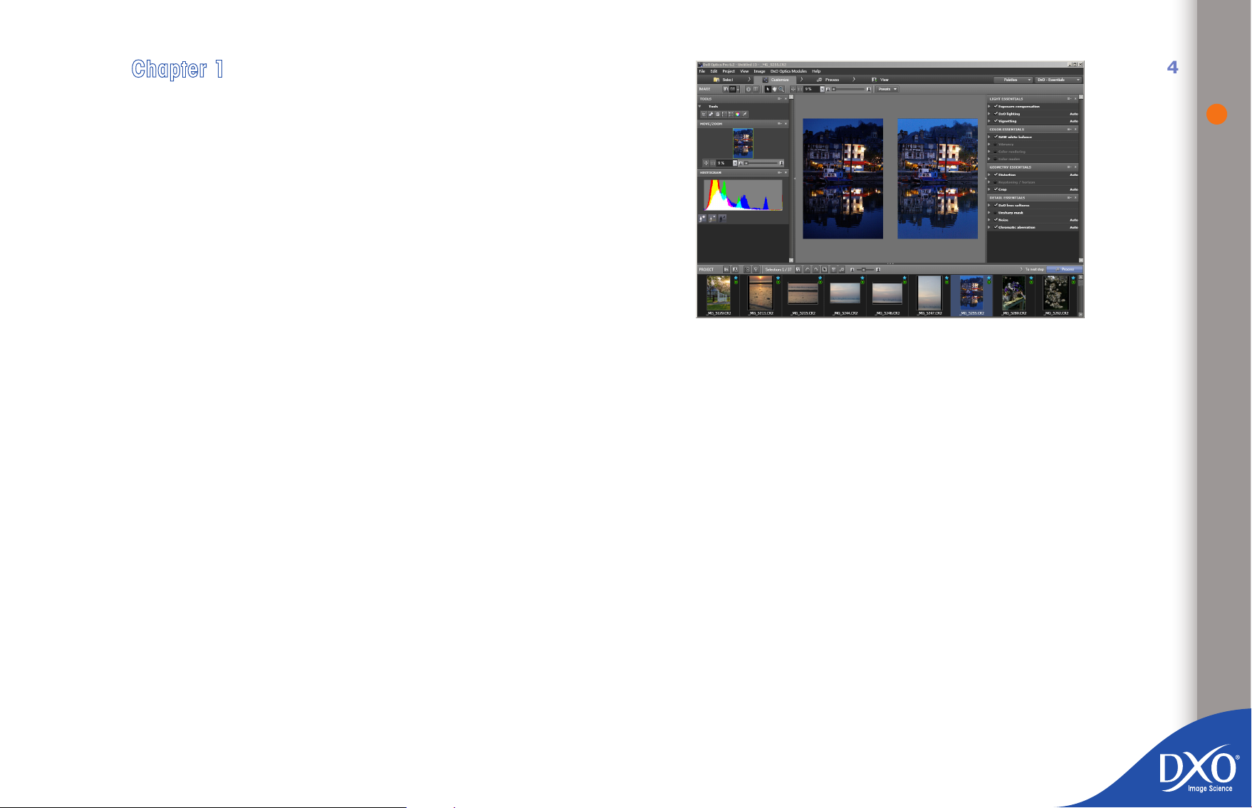
Introduction to DxO Optics Pro 6
4
DxO Optics Pro software improves your photos in just a few clicks of a mouse,
using powerful algorithms that automatically determine the settings required for
optimal picture quality, image by image, based on a detailed understanding of
the sensor and optics defects in over 2000 camera camera/lens combinations.
If your camera/lens combination is not included on the list of those supported by
DxO Labs, you will still be able to make the same range of optical corrections,
but you will have to adjust them manually.
Starting out from the basic corrections, you can add your personal touch to
optimizing your images, combining the choice of automatic correction for certain images and giving free rein to your creative spirit by carrying out manual
adjustments that go beyond simple correction.
The software can apply global and local optimization of highlights and shadows,
brightness correction, white balance, color, sharpness and perspective, distortion correction, vignetting – and even correct purple fringing and chromatic
aberration.
Note for users of DxO Optics Pro 5: a number of options available in version 5 have
been deliberately hidden by default in version 6, but can be shown by changing your
settings under ‘Preferences’.
1.1 The basic concept: automatic corrections
As everyone who has worked with photography knows, every image is unique,
even images from the same batch. There are an almost unlimited number of
factors that must be considered when taking a picture, such as type and model
Page 5
of camera and lens, image content, constantly changing weather and lighting
8
7
6
5
4
3
toc12
conditions, manual and automatic settings, the photographer’s personal taste,
and so on.
With lm-based photography, unless the photographer developed his or her
own lm and prints, much of the workow was left to professional development
houses. Digital photography has changed this and has moved control over all
aspects of the picture creation process into the hands of the photographer. As
well as actually taking the picture, this involves saving, correcting, creative
interpretation, archiving and much more... DxO Optics Pro offers you a range of
incredibly powerful image enhancement tools that you can integrate easily into
your own workow.
DxO Optics Pro does not work in the same way as other post-production programs. Rather than presenting you with an uncorrected image and expecting
you to make corrections and adjustments manually, DxO Optics Pro automatically determines the best combination of settings for each image you want to
process.
In fact, DxO Labs has calibrated and measured the defects in over 80 camera
bodies and in more than 2000 camera/lens combinations. The measurements
for each camera/lens combination are stored in a DxO Optics Module, which is
used by DxO Optics Pro to automatically correct the defects for this combination.
There are therefore as many DxO Optics Modules as there are calibrated camera/
lens combinations.
Provided the type of camera body you use to take your pictures has been calibrated by DxO Labs, DxO Optics Pro can:
convert and reduce noise in RAW images (e.g. CR2, NEF, RAF, etc.)
•
reduce noise in JPEG images
•
If, in addition, the DxO Optics Module for your camera/lens combination is available, you will have access to all DxO Optics Pro corrections, including automatic
optical corrections. If there is no DxO Optics Module available, you will still have
access to all of the DxO Optics Pro corrections but the optical corrections will be
in manual mode (adjustment by user required).
If the type of camera body used to take your photos has not been calibrated by
DxO Labs, DxO Optics Pro will not be able to read its RAW les but will still be
able to make corrections to its JPEG les, including manual optical corrections.
NOTE: If your workow involves using other software as well,
the DxO Optics Pro software must be used as the rst step in processing your images. See chapter 1.3 for further information.
1.2 Basic principles of an image enhancement
session
The way the DxO Optics Pro workow is organized deserves a few words of
explanation. Unlike traditional image editors, DxO Optics Pro works on projects,
not directly on images.
A project is a logical group of images that you want to process. The rst stage
in any project is therefore to add your images to it. As you add your images, a
combination of settings (a preset) that describes all the corrections that need to
be made is automatically associated with each one. Managing a project involves
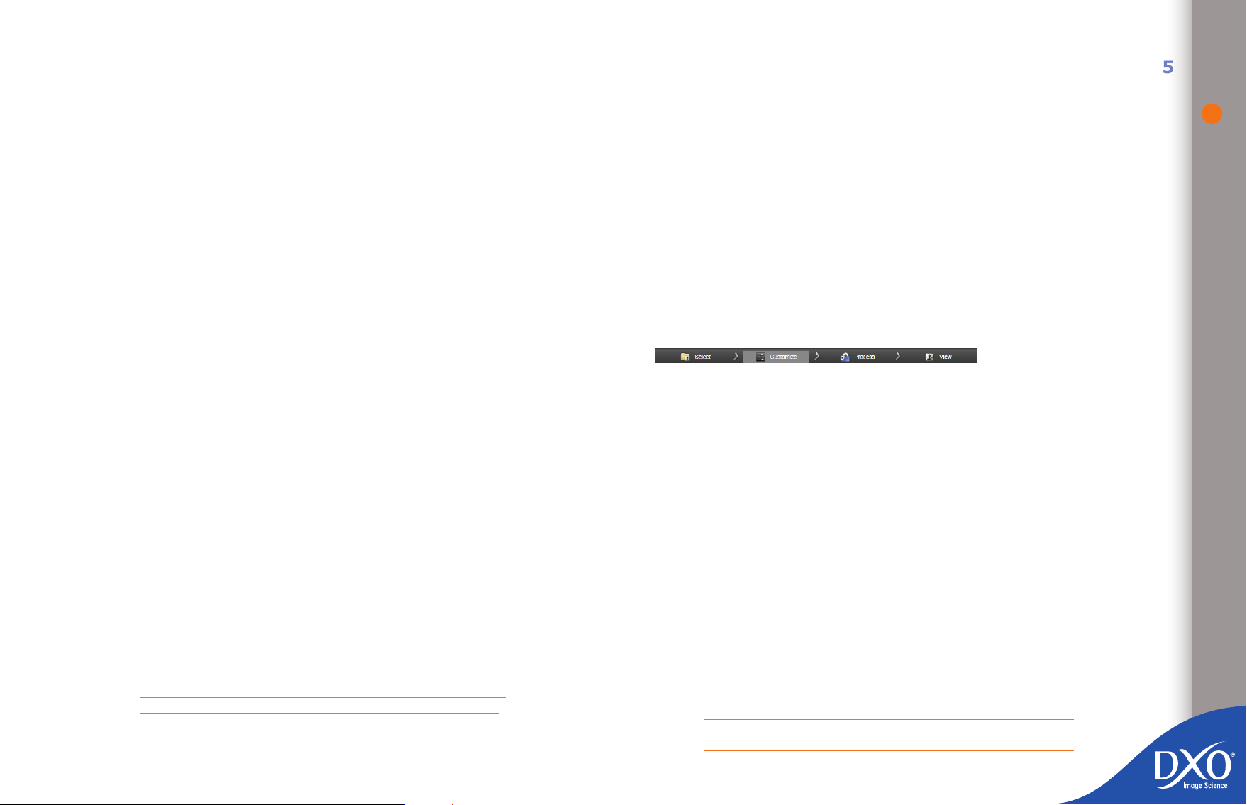
four main steps, each of which has its own tab:
Select
•
Customize
•
Process
•
View.
•
Two steps are essential: adding images to the project (“Select” tab) and then
the automatic processing of all the images in the project (“Process” tab). Note
that processing can also be started by right-clicking on one of the thumbnails in
the “PROJECT” pane (cf. chapter 3).
There is also an intermediate step, in the “Customize” tab, which allows you
both to preview the corrections that will be applied to your images when they
are processed, and to manually adjust certain settings on particular images. The
new settings are saved and will be applied when the image is processed (in the
“Process” tab). They can also be saved as presets and applied subsequently to
other images. If you close the software before you have processed your images,
but after you have saved your project, you will nd the same settings for these
images next time you open your project in DxO Optics Pro. Lastly, a nal step
(“View” tab) allows you to check the corrected images.
When you add an image to DxO Optics Pro, the program reads the information
stored in the image’s EXIF data about the camera and lens you have used. This
information is used to link the image to the appropriate DxO Optics Module
and to automatically determine the optimal optical correction settings for one.
Generally, you can then simply start the image processing without making any
manual adjustments to the settings.
REMEMBER: The image data read by DxO Optics Pro must not
have been changed since they were generated by the camera.
If the distortion, lens softness or vignetting corrections are not
5
Page 6

available in auto-mode, it means that the DxO Optics Module
8
7
6
5
4
3
toc12
you need has not been loaded onto your system or that the le’s
EXIF data have been changed or corrupted.
Example of a wide-angle lens, with (above) and without (underneath) a DxO Optics Module.
Your original image remains unmodied throughout the process. It is only during
the processing stage (activated in the “Process” tab) that DxO Optics Pro creates
a new image, which is still separate from your original image, and saves the
corrections to be applied in its own project database and (if the user chooses
this option) in a small additional le, known as a “sidecar”.
The rst time you use the software, it will be congured to save corrected images
as JPEG les, but you can choose from one of three output le formats, which are
described in more detail in the Processing chapter of this user guide, and even
generate several copies of the le in different formats (le type, compression
factor and image size) at the same time.
1.3 Additional post-processing:
DxO Optics Pro rst
DxO Optics Pro automatically identies the DxO Optics Module to use for your
images by reading the EXIF data from your pictures. These data are stored in
your image le and provide a wide range of information, such as the date the
shot was taken, the camera it was taken with, the focal length, aperture, aperture, speed and so on. Some cataloguing and retouching software can change or
corrupt EXIF data, which means DxO Optics Pro will not be able to identify the
appropriate DxO Optics Module or therefore automatically correct optical defects.
To make sure you can access the full range of DxO Optics Pro functionality, if
your workow involves using other software as well, the DxO Optics Pro software
must be used rst and you must proceed as follows:
6
1. Copy the data from your camera or memory card using your computer’s
operating system rather than an upload program, even one provided by
the manufacturer
2. Process the images in DxO Optics Pro and save the copies in a working
directory
3. Then go on to the other steps in your post-production process, particu-
larly local retouching or preparing prints, for example using the various
You may want to change the settings for the corrections applied to one or more
images. In the “Customize” tab, you have access to various workspaces where
you can access an increasing number of settings, so that you can gradually rene
your settings at an increasingly complex level.
TIP: You can restore the software’s default values in the rollups
by rechecking the auto-mode option to the right of the sliders
(‘magic wand’ icon). Otherwise, you can simply use the DxO
default v2 preset to restore all settings to their default value.
It is important to note that if you rst open your RAW les with Adobe Photoshop
or Lightroom to convert them into TIFF or JPEG les, DxO Optics Pro will not be
able to process optical defects (such as vignetting, lens softness, distortion or
chromatic aberration) automatically because the conversion changes the le’s
EXIF data. The same applies with most manufacturers’ conversion software,
except for recent versions of Nikon Capture.
versions of Photoshop™ or any other post-processing software
Page 7

If you want to manage your photos in an image database manager, don’t ins-
8
7
6
5
4
3
toc12
tall your original RAW or JPEG les into it, but only copies and photos already
correc¬ted by DxO Optics Pro
With Adobe® Photoshop Lightroom™, however, you can make use of the option
to select DxO Optics Pro as an external editor: this will make DxO Optics Pro
the default program for opening RAW les so that it can apply its corrections
automatically.
7
Page 8

Chapter 2
8
7
6
5
4
3
toc12
Your rst automatic processing session
DxO Optics Pro has been designed to be simple and efcient in every way. This is
particularly important for photographers who have to process a large number of
images. You can nd out how quick and easy DxO Optics Pro is to use in just a
few minutes before you go on to explore the settings explained in the rest of this
document.
2.1 Step 1: Selecting images
Unlike traditional image editors, DxO Optics Pro works on projects, not directly
on images. As chapter 1 explained, a project is a logical group of images that
you want to process. You are therefore going to create a new project by adding
images that are then processed individually based on the settings you have cho-
sen. To try this out for the rst time, select a few photos you know well!
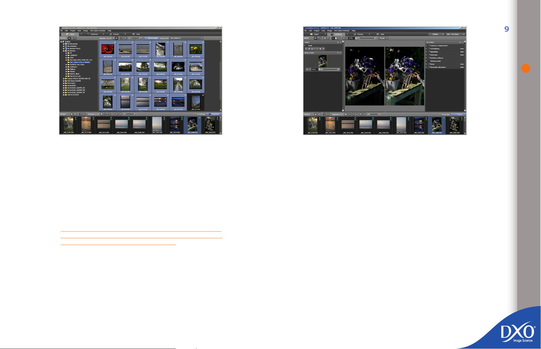
To do this, add your images to the “PROJECT” pane in the lower part of the
workspace in the “Select” tab. In the upper left-hand section of the “BROWSE”
pane, click on the “File system” icon: a browser showing the contents of your
hard disk will appear in the left-hand column. Select the folder where your images
are stored. You will see their thumbnails or le names appearing in the right-
hand pane of the main window: you can choose to view them in list mode or as
thumbnails of various sizes.
To import one or more images, simply drag and drop your les into the “PROJECT”
pane. You can also select images with your mouse using Shift + Click or Ctrl
+ Click. When you add images, you are not creating additional copies of your
images, but merely recording references to them in a le that keeps track of all
the details of your project. This helps make efcient use of the space available
on your hard disk.
8
Images in the top left pane and that have been added to the Project are labeled
with a white check
Page 9
9
8
7
6
5
4
3
toc12
“Select” tab
At the top of the window on the “Select” tab, the dropdown menu to the right of
the “Add to project” button is set to the “DxO Default v2” preset by default. When
you add images to the project, each of the images you add is automatically linked
to a combination of settings (a preset), which determines all the corrections to
be applied to the image. If you do not want to use the default preset, you can
select a different one, either one from DxO Labs or one that you have created
yourself. For your rst attempt, we recommend you use the default preset, which
applies all the software’s automatic corrections.
TIP: for expert or pro users working with RAW formats, you can
achieve a more natural color rendering by selecting the “DxO
Default v2 - Neutral color (RAW only)” preset
2.2 Step 2: Adjusting the correction settings
Under the “Customize” tab, the project to which you have just added your images
appears in the lower part of the screen in the “PROJECT” pane and shows the
images you have added to the project. Above this pane, you will see the “IMAGE”
pane, which allows you to preview image corrections. When you click on a thumb-
nail in the “PROJECT” pane, you will rst see an uncorrected version of your
image displayed, followed a few seconds later by a view of the corrected version
(clicking on the image lets you toggle between ‘after’ and ‘before’ views). You can
also choose to display two images side by side, “before” and “after” correction.
“Customize” tab: example of “before/after correction” display, in the “DxO – First steps“
If you are not satised with the default correction, the simplest thing is to try
a different preset from the dropdown menu. You can also, however, adjust the
settings applied to your images manually, using the correction palettes. These
palettes are organized in “workspaces”.
The “DxO - First steps” workspace
•
The “DxO – Essentials” workspace
•
The “DxO – Advanced user workspace
•
Only the “DxO - Advanced user” workspace gives you access to all possible settings, however you can move instantly from one workspace to another.
For your rst attempt, we recommend that you concentrate on the “DxO - First
steps” workspace and explore how a simple action with a slider can change your
photo. To evaluate sharpness and noise reduction, display the image at 75% or
more. This “DxO - First steps” workspace lets you access the following rollups:
Exposure compensation, which can be used to lighten or darken the
•
image, but also to recover overly white highlight detail from a RAW le;
DxO Lighting, which can be used to balance the overall contrast of an
•
image and lighten shadows;
workspace
Page 10
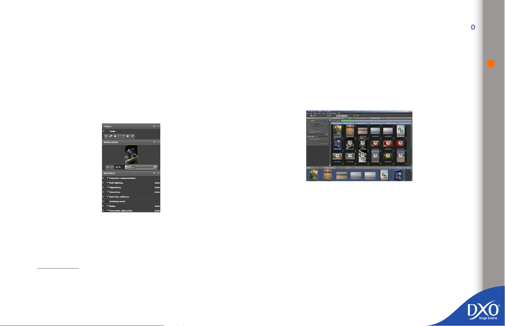
Vignetting, to compensate for the optical defect that darkens the cor-
8
7
6
5
4
3
toc12
•
ners of the image1;
Distortion, to compensate rounded distortions of the image2;
•
Lens softness, to correct the inherent lack of sharpness of the lens3;
•
Unsharp Mask, to correct the photo’s overall sharpness3 (Essentially
•
useful when the “Lens softness” rollup is not available because the
appropriate DxO Optics Module is absent);
2.3 Step 3: Image processing
Once you are satised with the settings you have applied to your images, you
can process them to generate a corrected copy incorporating all of your settings.
The rst time you use the software, it is congured by default to generate highquality JPEG les and save them in the same directory as the original images.
After you have clicked on the “Start processing” button to start the process, the
thumbnails selected for processing are displayed and a progress bar shows you
how much of the process has been completed.
10
Noise, to automatically remove noise, depending on the ISO setting
•
used to take the picture4;
Chromatic aberration”, to remove chromatic aberrations and purple
•
fringing5.
Palettes and rollups available in the “DxO - First steps workspace”
You can try out the effects of these very powerful corrections on a few test ima-
ges: moving the sliders even slightly can have a signicant effect! Never forget,
though, that all these corrections are reversible, because they don’t affect your
original le: so when you rst try out the software you can play with going a bit
too far to learn how the software behaves.
A clock appears over images that are waiting to be processed and two cogs over
those that are currently being processed. A green tick replaces the asterisk once
processing is complete.
“Process” tab
2.4 Step 4: Viewing results and
making adjustments
Once processing has nished, you can check the nal images in the “View” tab.
1 Automatic or manual adjustment depending on whether or not you have the appropriate
DxO optics module
2 Automatic or manual adjustment depending on whether or not you have the appropriate
DxO optics module
3 To see the effect of this correction, the display must be set to at least 75%
4 To see the effect of this correction, the display must be set to at least 75%
5 To see the effect of this correction, the display must be set to at least 75%
Page 11
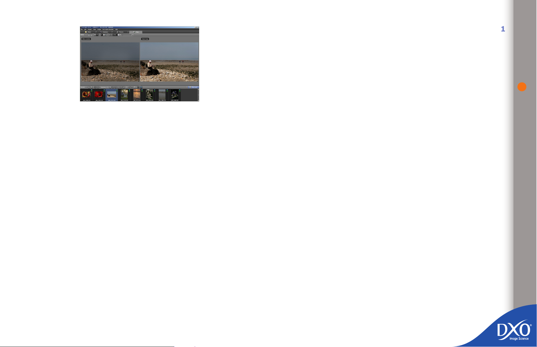
“View” tab
8
7
6
5
4
3
toc12
If you are not completely satised with the results, you can go back to the
“Customize” tab and make the necessary adjustments. When you restart the
process, only the images for which you have changed at least one setting will
be processed; the new versions will overwrite the previous corrected version.
To avoid overwriting the previous versions, use the “Virtual copy” functionality
explained later on in this guide.
11
Page 12
Chapter 3
8
7
6
5
4
3
toc12
“Select” tab
“Select” tab
3.1 Creating a project
When you open DxO Optics Pro, the application opens at the rst tab, “Select”,
which you use to add images to your project. A project is a logical group of
images that you want to process during your session.
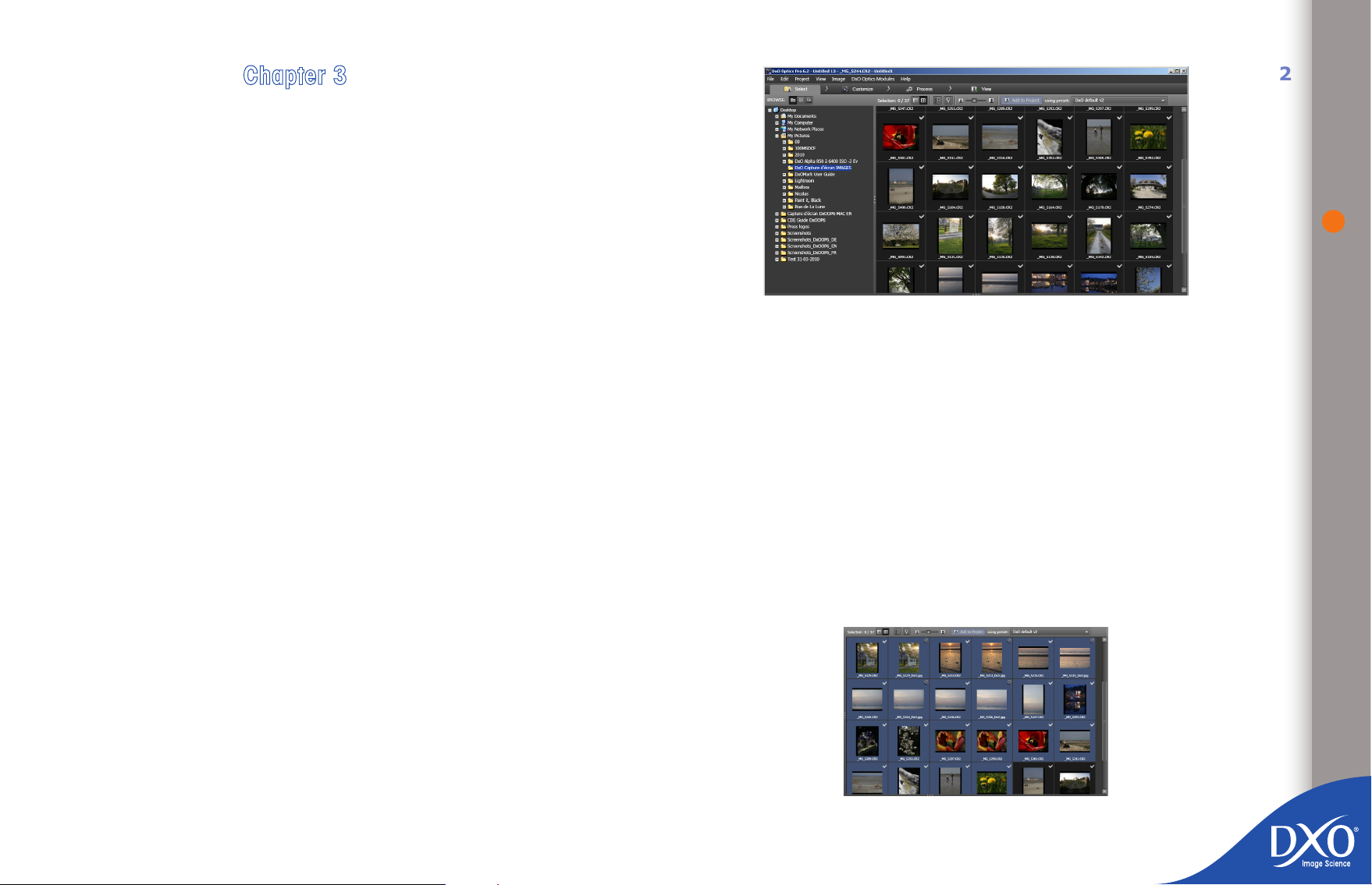
The tab is split into three panes:
The left-hand pane, “BROWSE” is used to navigate through the direc-
•
tories on your hard disk, or the database of your previous projects, or
your Lightroom catalogs if this program is installed on your system
12
The right-hand pane, shows the content of the directories or catalogs or
•
projects selected in the “BROWSE” pane
The “PROJECT” pane at the bottom is where you will place the images
•
you want to process
“Thumbnail mode” display. Grey blue thumbnails are selected thumbnails.
Page 13
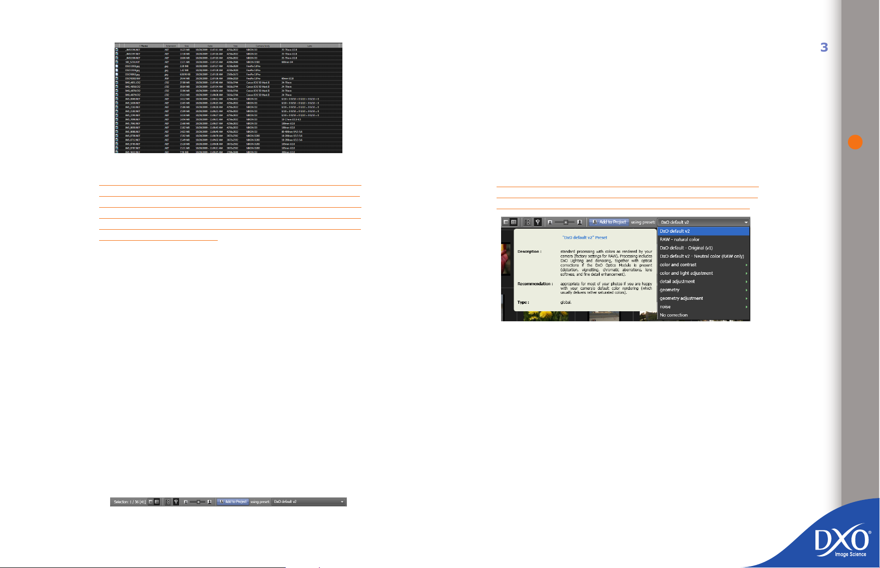
“List mode” display
8
7
6
5
4
3
toc12
TIP: If you can’t see all three panes, check that the vertical
and horizontal separation bars have not been moved to the very
top or bottom or side of the screen. The separation bars can
be identied by the three dots in the middle of the separator.
Simply slide the bar from the edge of the screen to the centre
to restore the invisible pane.
3.1.1 Selecting images using standard navigation
When you rst launch the application, the “BROWSE” pane is congured to navigate through the directories on your hard disk. Simply navigate to the directory
where you have saved the images you want to add to your project. Once you
have selected the directory you want, its contents will be displayed in the righthand pane, either in the form of a list or as thumbnails (select from the “View”
menu or the icons in the icon bar of the “Select” tab). Your images can be sorted
or ltered to only show RAW or RGB les, etc.
You can adjust the size of the thumbnails in the right-hand pane using the slider
in the icon bar in the same pane.
You will see some gures to the right of the “Selection” label on the icon bar of
the “Select” tab.
If you see a display such as 1/36, the 1 indicates the number of images selected,
whilst the 41 refers to the total number of images in the selected directory. If you
see a display such as 1/36 [41], the 1 indicates the number of images selected,
36 refers to the total number of visible images in the selected directory, and 41
indicates the total number of images in the selected directory. This means that
a lter has been activated to mask some of the images.
To add images to your project, select the appropriate lines or thumbnails in the
right-hand pane and then click on the “Add to project” button (in the icon bar of
the “Select“ tab) or drag and drop them into the “PROJECT” pane. In either case,
the images you have selected will appear in the “PROJECT” pane (at the bottom)
with a preset for the correction settings to be applied to your images. You can
choose to link a different preset to your images when you are adding them to the
project (from the dropdown menu in the icon bar of the “Select” tab). For your
rst few attempts, keep the default ‘DxO Default v2’ preset. You will be able to
change the preset for the images in your project later by right-clicking on the
thumbnails in the project or in the “Customize” tab.
In chapter 4.6 of this guide, you will nd out how to create your own presets.
NOTE: when you close the software, the last preset selected
(from the dropdown menu on the icon bar of the “Select” tab)
will be saved and used by default next time you add images.
Access to presets
Of course, if you need to apply different combinations of settings to different
images in a project, you can add the rst batch of images with a rst preset, and
then select and apply another set of parameters to the second batch. Remember
that each image in your project is treated individually, which means that you
have practically unlimited exibility in terms of processing options: you can even
choose a different preset for each separate image, even though they are all in
the same project. This very advanced level of customization within an overall
batch-processing framework is one of the real strengths of DxO Optics Pro and
distinguishes it from many other software programs that rely on a single “recipe”
for each batch processed. Images in the top left pane and that have been added
to the Project are labeled with a white check
13
Page 14
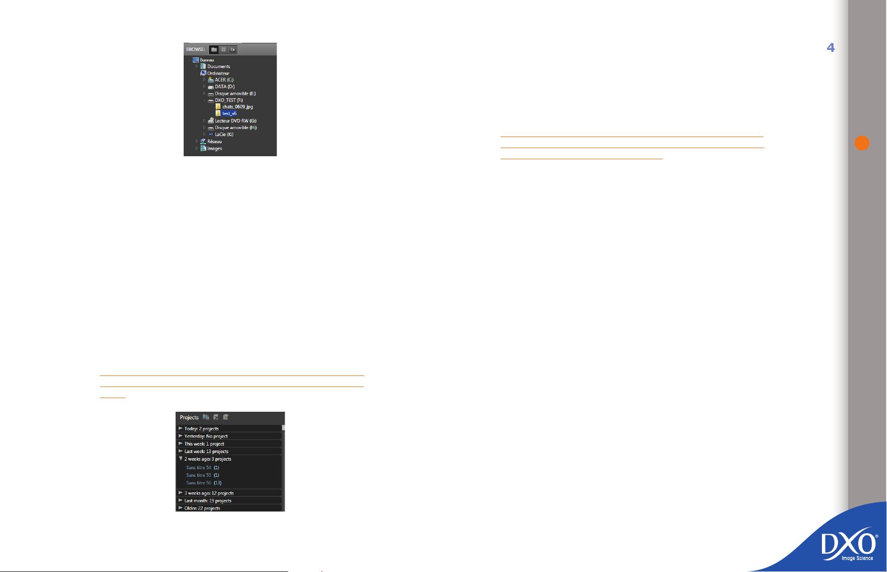
“File directory” browsing
8
7
6
5
4
3
toc12
3.1.2 Selecting images from the database of previous projects
In the same way that you can browse your hard disk to nd images, as explained
in the previous section, you can also navigate through the DxO project database
to nd a previous project. To do this, select the “Database” icon from the group
of icons at the top of the “BROWSE” pane. When you click on the icon, the lefthand pane is updated to show a chronological list of the projects you have already
processed (it will be empty if you are using DxO Optics Pro for the rst time).
If you click on one of your previous projects, you will see the thumbnails for all
the images that belong to this project appear in the right-hand pane. To upload
this project, double-click on the project name (or select the project name and
upload by right-clicking).
You can also access a project that has been saved in the project database from
the “File” menu > “Open project”. These are listed in chronological order, with
the most recent project processed at the top of the list.
NOTE: if you move your source images after you have run a
project, DxO Optics Pro may not be able to nd them to run it
again
3.1.3 Selecting images from a Lightroom catalog
If you have Lightroom catalogs stored on your hard disk, you can browse them
directly to select your images. To do this, select the “Adobe Lightroom catalogs”
icon from the group of icons in the upper right-hand corner of the “BROWSE”
pane. When you click on the icon, the left-hand pane is updated to show the list
of Lightroom catalogs stored on your computer.
NOTE: if your images have been transformed or converted from
RAW to JPEG by Lightroom, DxO Optics Pro will not be able to
apply optical corrections in auto-mode.
3.1.4 Selecting images from multiple sources
You can create projects in DxO Optics Pro using content from a single or multiple
folders. However, you can only display the content of one folder at a time in the
right-hand pane. If you create a project with content from several folders, select
the images in stages, starting with your rst folder and then your second folder
or a Lightroom database: this will ensure that all your images will remain in their
proper folders but will be combined in a single project.
3.2 “PROJECT” pane
Once you nished selecting your images, the “PROJECT” pane will show all the
images you want to process. You will be using this pane at every stage in the
process: “Customize”, “Process” and “View”. You can go back and add more
images to your project at any time.
The “PROJECT” pane is positioned by default at the bottom of the screen but you
can use the “View” menu > “Unlock PROJECT window” (shortcut Ctrl + Shift +
F) to make it oating, including positioning it in full-screen mode at the top of
the screen in whichever DxO Optics Pro tab is active, for example if you have a
large number of images to sort.
14
“DxO Optics Pro project database” browsing
Page 15
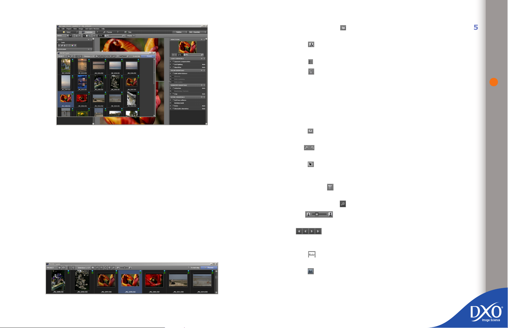
Floating “PROJECT” pane
8
7
6
5
4
3
toc12
The “PROJECT” pane can be resized as you want by moving the separation bar
with your mouse. There is a scroll-bar on the far right-hand side so that you can
display all of the images in the project in turn when you use a height equal to
one or two rows of thumbnails.
Simply click on “To next step” to the right of the separation bar to change
tabs from “Select” to “Customize”, “Customize” to “Process” and “Process” to
“View”.
Most of the commands in the “PROJECT” pane are also accessible from the menus
or from the optional icons shown on the thumbnails. A context menu accessible
by right-clicking with your mouse (Ctrl + click on a Mac) also gives you access
to a range of different options, including creating stacks if this function has been
activated in your preferences.
an information button you can use to show the project properties in
•
a separate window;
a button that takes you back to the “Select” tab so that you can add
•
more images;
a button for sorting the images in the project;
•
a button for ltering the images in the project;
•
a display such as 1/36, where the 1 indicates the number of images
•
selected, whilst the 41 refers to the total number of images in the selected directory. If you see a display such as 1/36 [41], the 1 indicates
the number of images selected, 36 refers to the total number of visible
images in the selected directory, and 41 indicates the total number of
images in the selected directory. This means that a lter has been activated to mask some of the images.
a button for showing the properties of the selected image: this opens
•
a new window displaying the properties of this particular image;
arrows for rotating the image if it is not automatically displayed the
•
right way up;
a button for creating a virtual copy, i.e. a duplicate copy of the image
•
to which you can apply different corrections than those used for the rst
image you selected;
the “recycle bin” button to remove the selected image from the pro-
•
ject (this does not delete the original le);
the processing button to start image processing;
•
a slider for changing the size of the thumbnails displayed in
•
the “PROJECT” pane;
15
the buttons that are only visible in the in the « Customize »
3.2.1 Icon bar
The icon bar sits at the top of the “PROJECT” pane. A tool tip appears for each
icon when you hover over it with your mouse:
Reading from left to right, you have:
•
and « View » tabs in case of a multiple selection. They will allow browsing
within the multiple selection without loosing it.
a button for sending images to Flickr photo galleries (only available
•
in the “View” tab);
a button for sending images to Adobe Photoshop Lightroom software
•
if you have this installed on your computer (only available in the “View”
tab);
a button that takes you on to the next step.
•
Page 16
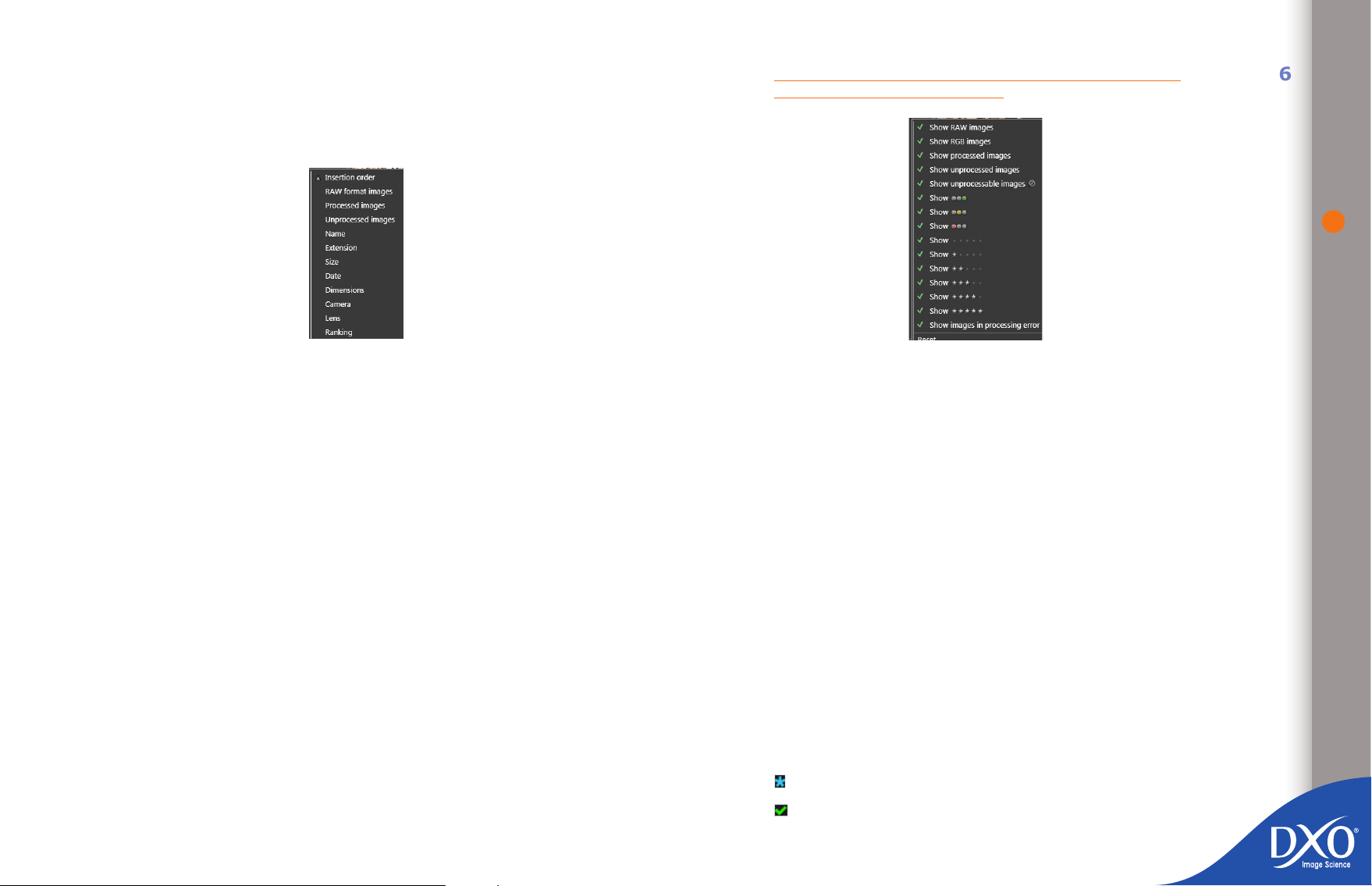
TIP: Sorting and ltering images.
8
7
6
5
4
3
toc12
Sorting and ltering images work in exactly the same way in the right-hand pane
and in the “PROJECT” pane. Sorting consists of ordering your images based on
criteria selected from a dialogue box that you access from the Sort button.
NOTE: Images that are not displayed cannot be selected for the
customization or processing stages.
16
Sort menu
The options available for the Sort button are as follows:
Insertion order in the project
•
Image format
•
Name – alphanumeric by lename
•
Name – by le name in alphanumeric order
•
Extension – used to separate different types of RAW, JPG and TIFF
•
images
Size – by size of le
•
Dimensions – by size of le dimensions (denition)
•
Date – by le modication date. This option is useful for doing a quick
•
search of the most recent image les in a folder
Camera – by type of device
•
Lens – by type of lens
•
Ranking – by star rating (only visible if this option has been enabled in
•
preferences).
Filtering affects which thumbnails are displayed in the “PROJECT” pane: if
you uncheck an item on the list the images with these characteristics will be
invisible.
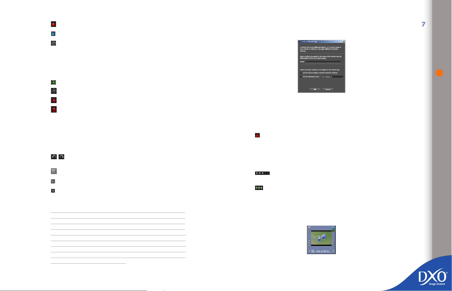
Filter menu
Show RAW images – When this option is checked, RAW image les are displayed in the “PROJECT” pane. If it is unchecked, RAW les are not displayed.
Show RGB images – When this option is checked, RGB image les (usually
JPG or TIFF) are displayed in the “PROJECT” pane. If it is unchecked, RGB les
are not displayed.
3.2.2 Thumbnail icons
The thumbnails shown in the project “PROJECT” pane include information and
icons you can activate to access certain functions. From the “Edit” menu >
“Preferences...” (see chapter 7) you can select which icons are always shown
in the edges of thumbnails, never shown or shown when you mouseover the
thumbnail.
The default icons are shown on thumbnails the rst time you run DxO Optics
Pro.
3.2.2.1 Default icons:
File name, processing status and the DxO Optics Module status are shown by
default.
Processing status is indicated by:
waiting for processing
•
processed
•
Page 17
processing error
8
7
6
5
4
3
toc12
•
not to be processed
•
cannot be processed
•
Images that are too small cannot be processed by DxO Optics Pro. Similarly, the
program cannot reprocess images already generated by DxO Optics Pro (output
images).
Module status is indicated by the following icons:
DxO Optics Module ready
•
no DxO Optics Module available for this image
•
DxO Optics Module available for download
•
By combining virtual copies and output options (see chapter 5) you can access
an almost unlimited number of processing combinations.
Virtual copy creation window
17
DxO Optics Module ambiguity.
•
Click on the red arrow icon to download the specied module. The icon will go
back to green once the download is complete. If you click on the red question
mark, a dialogue box will appear so that you can choose the right optics module
(e.g. between a Nikkor 12-24 f/4 and a Tokina 12-24 f/4, which have identical
EXIF data) either for a particular image or for the whole project.
Other symbols will appear if you hover over the thumbnail with your mouse:
for rotating the image: these function in the same way as the
•
icons on the command bar in the “PROJECT” pane:
can be used to remove an image from the project;
•
indicates that this image is a virtual copy;
•
indicates that images are presented in the form of a stack.
•
TIP: Creating a virtual copy (see chapter 4.3 for more details)
allows you to apply different settings to the same image at the
same time, rather than going backwards and forwards between
customizing settings and processing images. When you activate
the “Create a virtual copy” command, a dialogue box will ask
you to select the settings to be associated to the virtual copy,
and the sufx you want to add to the name of the copy. For
example, if you want to process the same image in color and
black and white at the same time, create a virtual copy called
“BW” by applying an ad hoc preset.
3.2.2.2 Additional icons
From the “Edit” menu > “Preferences...” > “Display” you can select other icons
to appear next to your thumbnails in the “PROJECT” pane:
indicates that the focal length and/or focusing distance haven’t been
•
properly written by the camera body in the image’s EXIF. This lack of
information may slightly affect the precision of the automatic distortion
correction. These data can be manually entered in the rollups under the
geometry palette. By default, DxO Optics Pro sets the focusing distance
to innity, and the focal length to the value written in the EXIF data;
can be used to score your images and rank them by quality; they
•
can then be sorted on the basis of their ranking;
the ‘trafc light’ indicators are used to show you which images are
•
to be processed (green light), must not be processed (red light) or where
no decision has been made (yellow light: this is the default value when
an image is added to a project). When processing begins, images with
green and yellow lights will be processed, whereas images with red lights
will not be processed.
Thumbnail inThumbnail in the “PROJECT” pane (all icons enabled)
Page 18

3.2.3 Commands accessed by right-clicking
8
7
6
5
4
3
toc12
Right-clicking on a thumbnail opens up a context menu, whose commands may
change depending on the preferences selected when customizing the software
(see chapter 7) or on the properties of the image selected.
When all options are turned on, the following commands can be accessed by
right-clicking (Ctrl + click on a Mac):
Image properties;
•
Apply preset to image;
•
Create a preset from current settings;
•
Copy correction settings to paste them onto another image;
•
Paste the correction settings from another image via the clipboard;
•
Start processing
•
Rotate image to right or left;
•
Remove image from project;
•
Show input le in Windows Explorer;
•
Show output les in Windows Explorer;
•
Open input image using…;
•
Open output images using…;
•
Create a virtual copy;
•
Stack: stack images, set a stack master, add items to stack, remove
•
items from stack;
Allow processing: Flag: managing trafc lights, if this option has been
•
activated under “Preferences”.
Ranking: managing stars, if this option has been activated under
•
“Preferences”.
18
Many of these commands are also accessible by using the icons in the top bar
of the “PROJECT” pane or the thumbnail icons, but the quickest way of applying
a preset is to right-click.
3.2.4 Stack management
If image stacking is activated in “Preferences” (see chapter 7) and you have
grouped your images into stacks, the corresponding icon will appear on the rst
image in each stack.
A “stack” of images is used to organize your images into groups, not only to
reduce cluttering in the “PROJECT” pane but also so that you can apply different
settings to a whole group of images at the same time (without having to select
multiple images each time). In this sense, a stack is equivalent to a permanent
multiple selection.
It is worth thinking about making a stack whenever you have images that may
need the same processing parameters for one reason or another. It may be a
series of linked images on the same subject or a series of images taken in the
same lighting conditions, for example. The possibilities are endless.
A stack always has a “Master” image, the one which appears on the top of a
collapsed stack. This is the image shown on the “Customize” tab when you select
a collapsed stack.
Page 19
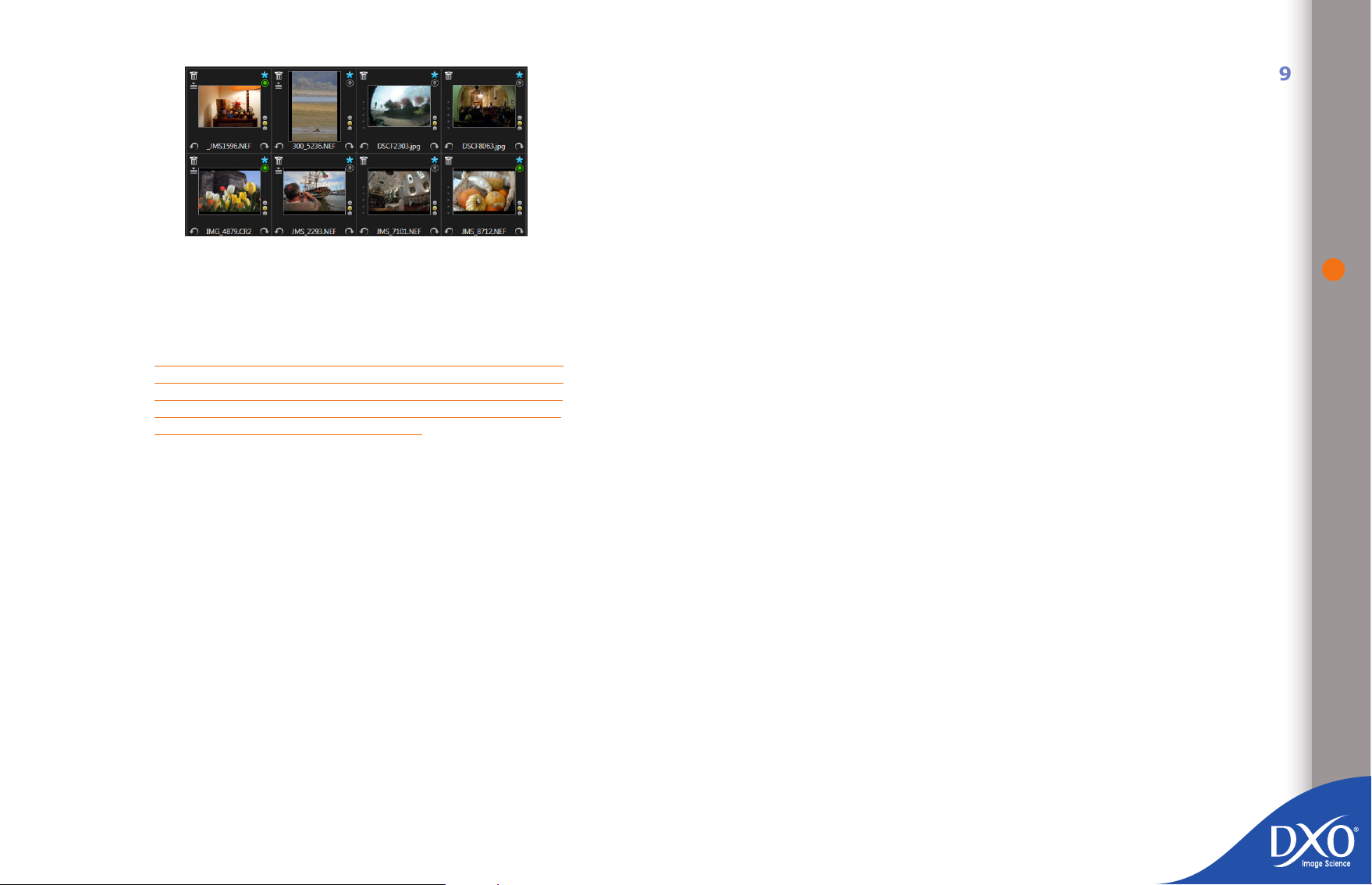
4 left-hand thumbnails are 4 stacks (see their stack icon)
8
7
6
5
4
3
toc12
Creating a stack. Creating a stack is easy: simply select a number of images
and then right-click on one of the images. A menu window appears and the
Stacking option is shown with an arrow pointing right. Click on this menu option
and a sub-menu will appear to the right.
TIP: To select a series of adjacent thumbnails to include in a
stack, hold the Shift key down and click on the rst and last
images you want to form the stack. To select images that are
not adjacent to each other, hold down the Ctrl key and click once
on the thumbnails to include in the stack.
Stack images. The Stack images option allows you to create a stack in
•
which the images to the left of the last image selected are stacked under
the last image.
Expand the stack by clicking on the stack icon to check each of the ima-
•
ges without having to unstack them. You can also expand the stack for
all the images in the stack in the “PROJECT” pane by right-clicking on
the stack and selecting Stacking and Expand stack.
Once a stack has been created, it stays as a group and can be managed and
manipulated in the same way as a single image.
19
Recreate the stack by clicking on the stack icon.
•
Change the “Master” image by using the wheel on your mouse, or a right
•
click.
Add other images. You can now add other images to the stack by right-
•
clicking on the stack and selecting Stacking > Add items to stack.
Remove items from stack. If you expand a stack and click on an image
•
to select it in the stack, you can then right-click and click Remove items
from stack in the Stacking sub-menu. This will remove the image from
the stack, but not from the project.
Unstack items using the context menu that appears by selecting Stacking
•
and then Unstack images.
Page 20

Chapter 4
8
7
6
5
4
3
toc12
“Customize Settings” tab
Using the “Customize Settings” tab is optional, but it allows you to preview the
corrections made by DxO Optics Pro and make any adjustments to the settings
you want.
4.1 The “IMAGE” pane
The “Customize Settings” tab workspace is divided into two primary panes. The
top pane is the “IMAGE” pane, whilst the Project “PROJECT” pane continues to
occupy the lower part of your screen. To work on an image, simply click on an
image thumbnail in the “PROJECT” pane: the image will appear in the “IMAGE”
pane with a preview of the corrections made.
In fact, the rst image to appear will be the ‘before’ image (the original image
you imported into DxO Optics Pro). Then, after a few seconds, this will be replaced by a preview of the ‘after’ image. A message will remind you that you need
to view the image at a zoom of at least 75% to see the effect of corrections on
sharpness, noise and chromatic aberrations. Click on the information symbol to
avoid seeing this message again
Several icons appear from left to right beneath the menu and tab bars:
“Single image display”: displays a preview of the image as it will be
•
corrected. The keyboard shortcut CTRL + D for Windows or CMD + E for
Mac lets you toggle the display between “Corrected image” / “Reference
image”, which by default is the uncorrected image, but can be changed
as explained in the “Reference Image” section below.
20
“Dual image display”: displays the reference image – by default, the
•
uncorrected image – and a preview of the image as it will be corrected
by DxO Optics Pro. You can zoom in if necessary to compare the detail
in the same area of each image.
“Reference image” dropdown menu: you can compare the current
•
image with various reference images. By default, the uncorrected image
is used as the Reference Image, but the dropdown menu lets you choose
another image. This feature is particularly handy when you have created
Virtual Copies. In this way, once these Virtual Copies have been processed, you can compare an image with the various Virtual Copies of it
and see the different corrections applied.
Information about the image: click on this button to show or hide the
•
captions “before correction”, “correction preview” and the information
screen about the image’s zoom factor;
Page 21
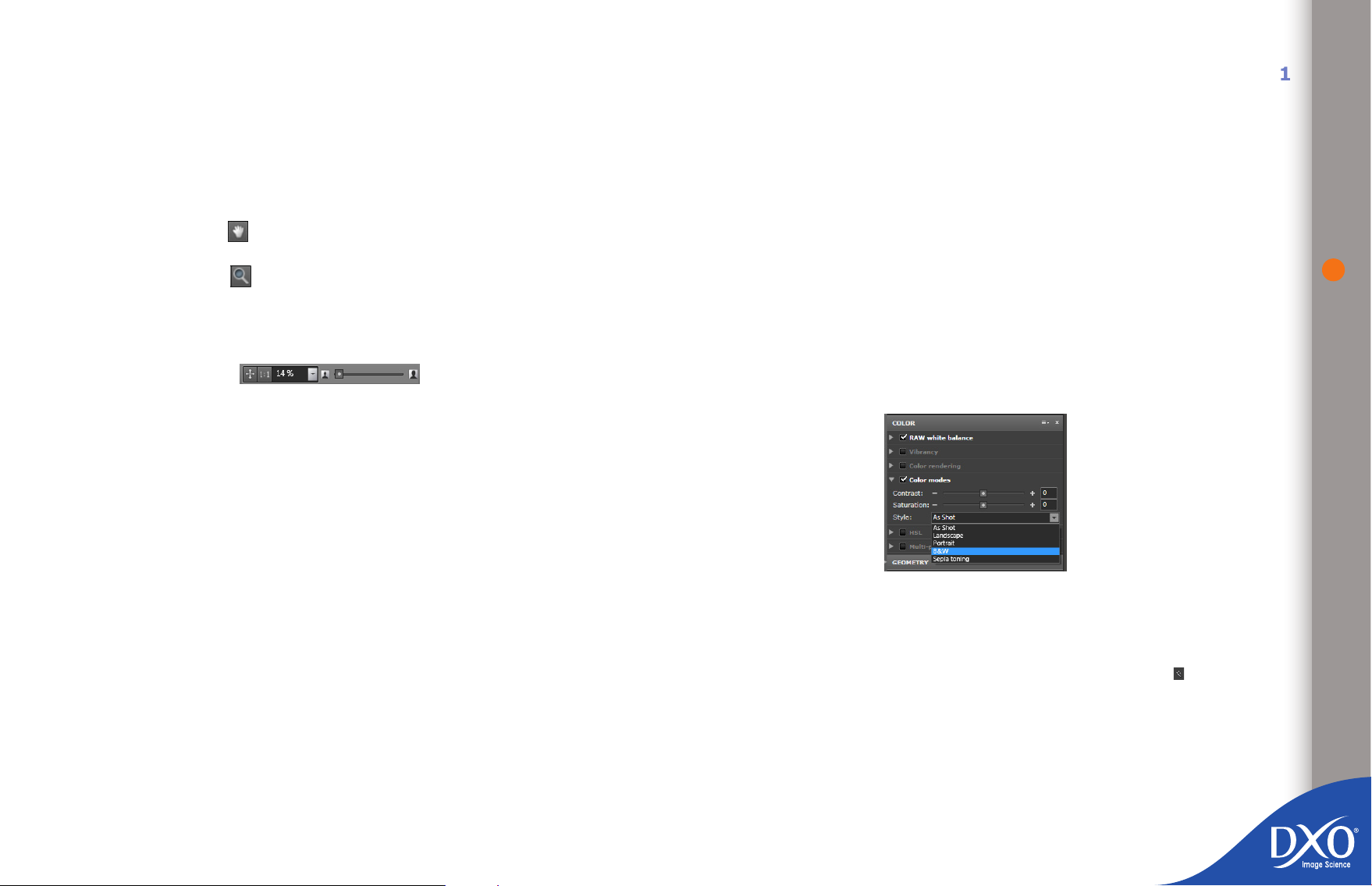
Grid overlay: Show a grid overlay over the image: this is particularly
8
7
6
5
4
3
toc12
•
useful for correcting distortion and keystoning;
Pointer tool – when this tool is active, and when the “Single image
•
display” mode is enabled, clicking on the corrected image will display
the reference image (see above) so that you can compare it with the
corrected version. Release the mouse button to return to the nal image
corrected by DxO Optics Pro. The keyboard shortcut “Ctrl + D” can also
be used to toggle between the “before” and “after” images.
Hand tool – The hand tool can be used to move the visible area of
•
the image.
Zoom tool – Click on this icon to zoom into the image in full-frame
•
view (using the thumbwheel on your mouse if it has one) up to a magnication factor of 1600%. It’s important to remember that when displaying
at zoom factors below 75%, this preview image does not show some of
the corrections to be applied.
Zoom slider to adjust the size of the image
•
displayed up to a magni¬cation of 1600%. Two quick commands can
be used to adjust the image to the size of the pane and zoom to 100%,
which is ideal for checking sharpness and noise.
Selection box for existing presets:
•
To the far right of the window you will see the dropdown menus for selecting
workspaces, correction and image checking palettes.
4.2 Adjusting settings
If you were satised with the results of the preset chosen in the “Select” tab, you
can go straight to the “Process” tab and start processing your images.
Otherwise, you can try out the various presets accessible from the icon bar with
just a click of your mouse to explore a wide variety of color rendering and saturation options, and much more. (There is more information about these presets
in chapter 4.5.2). If you want to make your own adjustments rather than use
the software’s automatic settings, you have three workspaces available to you,
each of which will give you access to a larger number of settings:
The “First Steps” workspace
•
The “Essentials” workspace
•
The “Advanced user” workspace
•
For a quick taste of how manual settings work, select the “Essentials” workspace,
open the “Color Essentials” palette and then the “Color modes” sub-palette: click
on the “B&W” style and see how your image is instantly transformed. Uncheck
the “Color Modes” box and it will revert to its original colors!
21
A palette is a logical group of sub-palettes. The “Light” palette, for example, combines all the sub-palettes used for lighting corrections (Exposure compensation,
DxO Lighting, Vignetting, Tone curve). A sub-palette combines all the settings
for the relevant correction.
A sub-palette is active when there is a tick in front of its name. The word “Auto”
to the right of the sub-palette bar means that corrections for this sub-palette
are automatically optimized for the image by DxO Optics Pro.
If you change a setting on a sub-palette and want to revert to the optimal value
recommended by DxO Optics Pro, simply click the small magic wand icon to the
right of the setting concerned.
A correction can be enabled (or disabled) by checking (or unchecking) the box
to the left of the subpalette name.
Open the correction palettes you want and change a few of the settings to see
the effect on the screen, for example to adjust the horizon in a landscape image
or correct a color balance.
To return to full auto-mode, simply click on the small magic wand icon to the
right of most of the sliders.
Note that in all the workspaces, even the simplest, you can use the “Tools”
palette to correct a sloping horizon or adjust keystoning. Your image will be
automatically reset!
Conversion to black and white using the “Color modes” sub-palette
Page 22
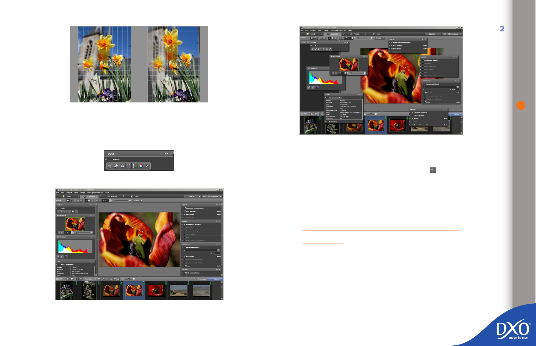
Keystoning correction
8
7
6
5
4
3
toc12
For your rst attempts, try to limit how many personal corrections you make so
that you can get an idea of how DxO Optics Pro automatically processes your
images. Later, if you want to, you will learn how to make more and more detailed
corrections to suit your preferences.
Tools palette
22
Workspace with oating palettes
If all palettes are displayed, DxO Optics Pro automatically positions them to
either side of the screen and keeps the image you are working on in the centre.
You can also move them around to wherever suits you best above or below your
image. To return a palette to its place, just click the small icon in the menu
bar to dock it to the right or left. This same icon also lets you hide the palette
to save space on the screen.
All the workspaces have a toolbar which you can use (from left to right) to crop
the photo, remove dust, adjust the horizon, correct keystoning, change the color
balance on selected parts of the image and correct the image’s white balance
with the color picker tool.
NOTE: Tools can be displayed directly in the “IMAGE” pane icon
bar by setting the relevant preference in the ‘Edit / Preferences
/ Display’ menu.
4.3 Virtual copies
When you are adjusting the settings on an image, you may nd that you want
to try out different settings on the same image at the same time. Virtual copies
are the perfect solution, as explained below.
You can create a virtual copy of the image by right-clicking on the thumbnail in the
Workspace with palettes anchored to the right of the image
“PROJECT” pane. A dialogue box will open and ask you to enter various settings to
associate with this image (a preset is automatically associated with it, just as it is
when you add an image to a project): these can either be the same settings as the
image you are making the virtual copy of, or a preset you can select from the list.
Page 23
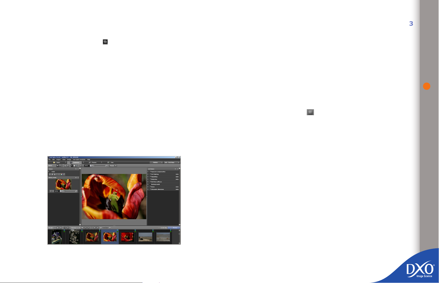
You will also be asked to enter a sufx to add to the name of the virtual copy to
8
7
6
5
4
3
toc12
distinguish it from the original image.
vents you from applying a more complex correction to an image where necessary.
This workspace includes the following sub-palettes:
23
Once the virtual copy has been created it will appear in the “PROJECT” pane and
will be shown with a special icon ( ) in front of its name. A virtual copy behaves in exactly the same way as a normal image. It can therefore be viewed in
the “IMAGE” pane, where its settings can be adjusted. When you process your
images, an output image will be generated for each virtual copy.
You can make as many virtual copies as you need.
DxO Optics Pro’s virtual copy functionality goes even further, because you can
compare virtual copies with each other quickly and simply: in the icon bar of
the “IMAGE” pane there is a dropdown menu with a default option of “Before
correction”. Using the dropdown menu you can specify which image to use as
a reference when comparing the corrections to the current image. By default,
the reference image is the uncorrected version. You can replace the reference
image with any virtual copy of the same image, provided that the virtual copy has
already been processed. You can access this functionality from the “Customize
Settings” and “View” tabs.
4.4 Workspaces
4.4.1 The “DxO - First steps” workspace
Exposure compensation: this allows you to recover over-exposed highli-
•
ghts in the photo almost miraculously when you are working with RAW
les.
DxO Lighting, which adjusts the contrast in the photo by lightening sha-
•
dows; if the overall image has had to be darkened to recover highlights,
shadows can be compensated to lighten dark areas.
Vignetting, which is used to compensate dark areas in the corners of the
•
image. This must be adjusted manually if you do not have a DxO Optics
Module.
Distortion, which corrects distortions to the image, particularly where a
•
wide-angle lens has been used. This must be adjusted manually if you
do not have a DxO Optics Module and it is helpful to display the grid
overlay over the photo (the icon in the bar above the images you
are working on) to give yourself some visual markers.
Lens softness, to correct inherent lens softness according to the data
•
in the DxO Optics Module, depending on aperture, focal length, and the
position of the pixel in the image eld. This correction is not the same
over the whole of the image, as DxO Optics Pro takes account of the
fact that a lens will be sharper in the centre than at the edges, and so
central pixels need less correction than ones near the edge of the eld.
This is one of DxO Optics Pro’s great strengths. An average setting has
been dened by DxO Labs, which corresponds to the “−0.5” slider position. You may want to change the basic setting, however: a portrait, for
example, can be made slightly softer than the default setting. To reduce
overall sharpness correction, move the “Global” slider to the left (note
that for negative values of the “Global” slider, the corrected image will
always be at least as sharp as the original image, unless you disable this
correction); to increase it, move the slider to the right. If you are using a
lens for which there is no Optics Module available, this subpalette will not
be visible, but you can adjust the sharpness manually in the “Unsharp
mask” subpalette, which will give a less satisfactory result because,
unlike the “Lens softness” subpalette correction, the same correction is
applied to all the pixels
Unsharp Mask: this correction can be used in addition to the “Lens
•
softness” subpalette. It affects all the pixels in the image to the same
extent.
Because you can add any palette to a workspace temporarily and even create
your own, deciding to work in the simplest space, “DxO - First steps”, never pre-
Page 24
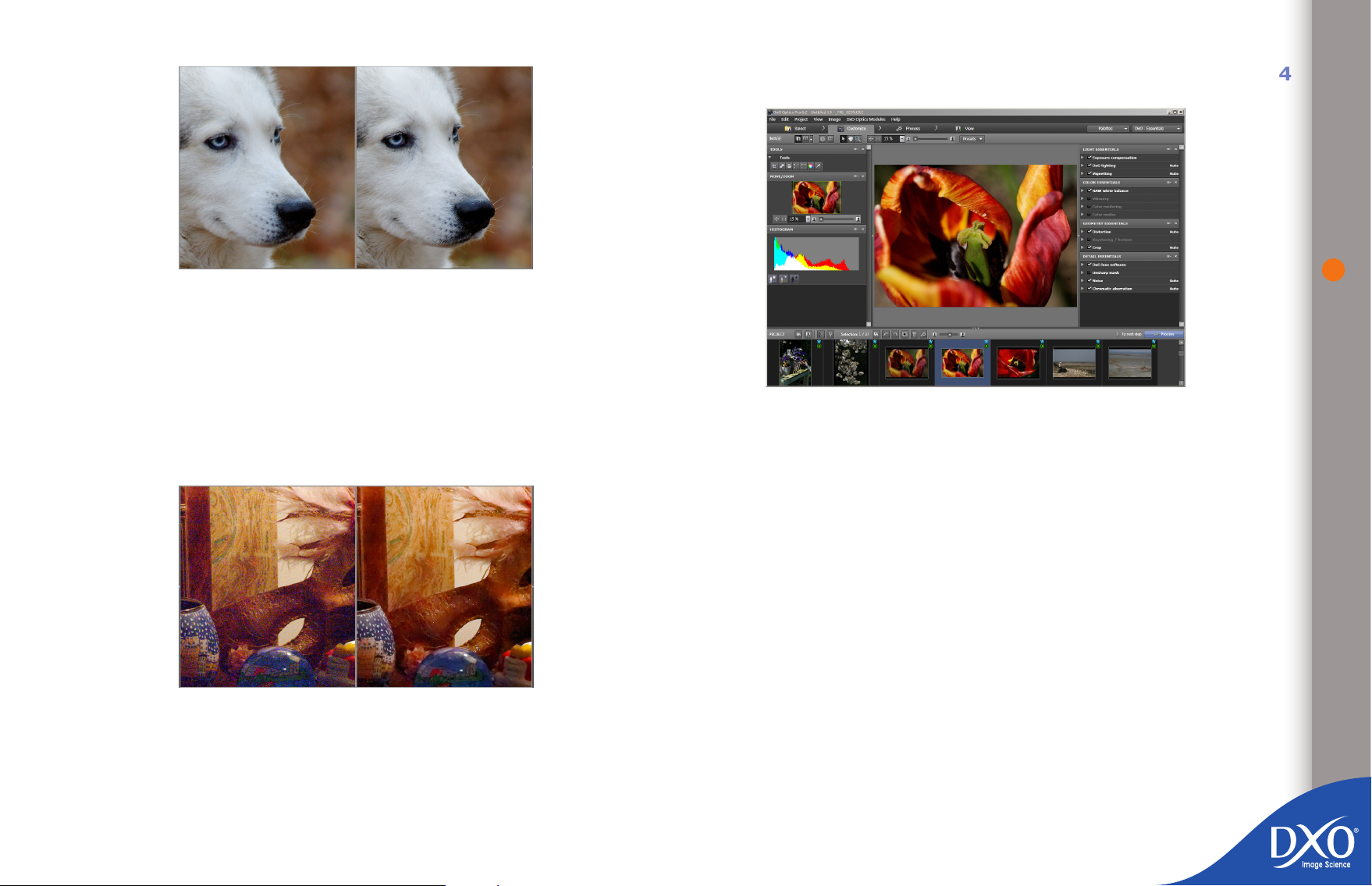
Checking and correcting lens softness with a display 75% (zoom = 75%)
8
7
6
5
4
3
toc12
Noise, to remove the spurious colors that appear at high ISO values. DxO
•
Optics Pro is extremely effective on RAW les, with additional settings
for correcting luminance noise (too high a level of correction reduces
detail sharpness), chrominance (to remove spurious colored lines), and
noise in grey shades, whilst a key to remove dead pixels eliminates the
tiny points of light that appear with some cameras.
Chromatic aberrations, to automatically remove the color defects caused
•
by a lack of precision in the lens and, by checking the appropriate box,
the purple fringing that can appear in starkly back-lit photographs.
4.4.2 “DxO - Essentials” workspace
If you select the “DxO - Essentials” workspace, you will nd the correction options
grouped into the following palettes
“Detail” which includes three of the sub-palettes from the DxO - First
•
steps workspace (sharpness, noise and chromatic aberration)
“Light”, which combines the three sub-palettes described above (expo-
•
sure compensation, DxO Lighting and vignetting)
24
“Geometry”, which in addition to distortion correction gives you a crop-
•
ping option and more detailed commands for correcting keystoning
“Color”, which you can use to rene white balance and correct vibrancy
•
(different saturation levels for neutral and bright tones), color modes
and color rendering.
Finally, the “Histogram” palette can be used to show areas of the image that are
too dark or too light (burnt-out whites) and the RGB values of the pixel at which
Noise correcting with 75% display
the mouse is pointing.
If you have the DxO FilmPack optional module, you can select the type of lm
in the “color rendering” sub-palette, but you will also need to open the “Detail”
sub-palette to make adjustments to grain.
For detailed color mode and style settings you can change the color rendering for
your camera (your Nikon can take Canon-style photos, and vice versa) and you
can choose a portrait or landscape style for a photo or batch of photos.
Page 25
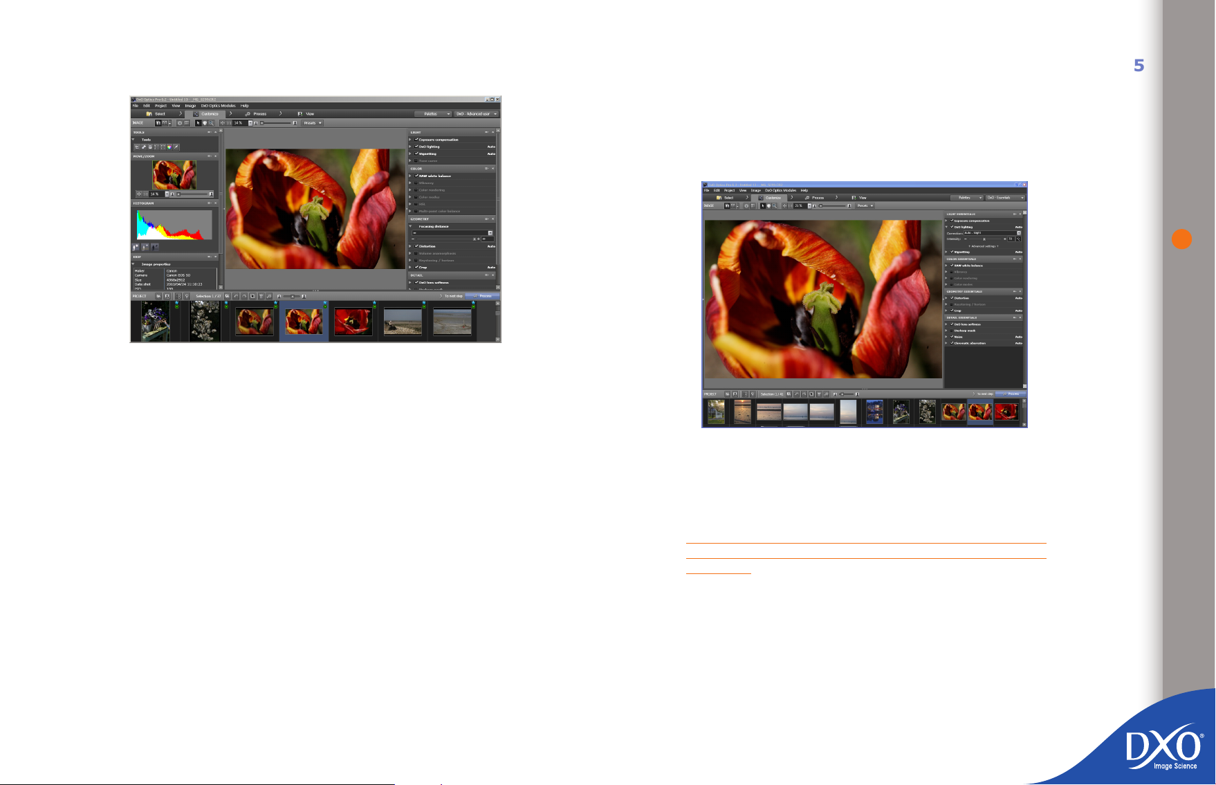
4.4.3. “DxO - Advanced user” workspace
8
7
6
5
4
3
toc12
All palettes and sub-palettes are available in the “DxO - Advanced user” workspace, where you can access the most sophisticated and most complex settings.
Some settings are effectively duplicated, as you can adjust contrast either with
DxO Lighting (black point, white point, gamma), with the tone curve or with the
color-mode sub-palette: be careful not to make cumulative or contradictory corrections. The same applies to saturation, which can be changed by using the tone
curve for each layer of color, the HSL sub-palette or the vibrancy sub-palette.
4.4.4 Creating your own workspace
DxO Optics Pro offers you a wide range of options for creating a working environment that’s personal to you, for example by creating your own workspace from
a combination of existing palettes or customized palettes with the sub-palettes
you use most frequently. Please note that the standard workspaces available in
DxO Optics Pro cannot be changed.
If you want to create a customized palette (My Palette, chapter 4.5.3), you must
save it in a workspace.
create a new customized palette using the “Palettes” dialogue box >
•
“Create user palette” and then name it, for example “RAW palette” ins-
tead of the default “My Palette”.
A RAW workspace, for example, might combine a Histogram, the Preset Editor
and the sub-palettes that are useful for processing RAW images in a single
palette.
Customized workspace
You can also start the customization process by creating your own personal
palette rst. Once you have created your personal palette, it can only be saved
by clicking on “Save workspace”; the workspace can have the same name as
the palette.
NOTE: full palettes can be combined in a workspace, however a
personal palette can only consist of sub-palettes, not of another
full palette.
You can create as many workspaces and personal palettes as you need, however
increasing the number of possible settings in this way is not always the best solution: presets can provide multiple correction options completely automatically.
25
To create a workspace, you can:
click on the “Save workspace” command in the “Workspace” dialogue
•
box and name it (for example, “RAW workspace”),
decide which existing palettes to include in your workspace, by clicking
•
on the “Palettes” dialogue box or by removing open palettes from the
DxO Advanced user workspace,
4.5 Detailed information for all settings
You can access the settings palettes from all workspaces using the “Palettes”
dialogue box to the top right of the “Customize” tab.
Four palettes allow you to move and enlarge the image (“Move/Zoom”), check
the color values in the image and identify any areas that are too dark or too light
Page 26
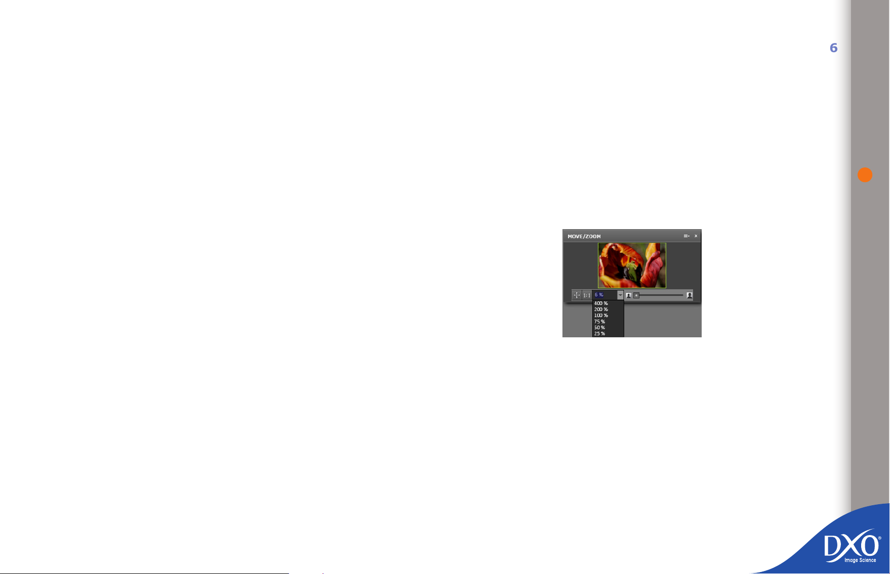
(“Histogram”), view information about the shoot (“EXIF”), and give you access
8
7
6
5
4
3
toc12
to shortcuts for a number of quick settings (“Tools”).
Four other palettes are used for making corrections to your images:
The Light palette includes exposure compensation, which allows you to adjust
the exposure after you have taken your shot and eventually restore highlight
details in some RAW images; DxO Lighting, which corrects image contrast intelligently, using local intensity adjustments; vignetting compensation, which corrects the dark areas seen in the corners of some images; and nally tone curve,
which offers very precise control over all luminance levels and for each of the
color layers in the image.
The Color palette includes white balance, which allows you to alter the lighting
color temperature and tint, with different adjustments for RAW or RGB originals.
You will also nd DxO Optics Pro’s exclusive “Multi-point color balance”, handy
for ne adjustments when a scene contains different colored light sources. The
Vibrancy function, on the other hand, brings out the more vivid colors in an image
while preserving medium tones, for example for portraits with a vivid background
but realistic skin tones. Another important tool gives you a choice of “color ren-
dering” proles. These proles let you apply a specic ‘look’ to your images, from
different cameras to traditional lm rendering using the optional DxO FilmPack
module, and importing external proles. The palette also includes sliders that
make it simple to adjust hue, saturation and lightness (HSL) and other controls
that you can use to assign styles to your images (landscape, as shot, etc.)
The Geometry palette is where you will nd controls for distortion, volume
anamorphosis and keystoning/horizon correction. Distortion correction is applied
automatically by DxO Optics Pro according to the type of lens used for the
pic¬ture and the photographic settings (zoom, aperture, etc.) as long as you
have the appropriate module; otherwise the distortion correction has to be
manually adjusted. Volume anamorphosis correction takes care of the geometric
distortion that stretches objects in the corners of wide-angle images. Being subject-matter dependent, this adjustment requires you to set the type and amount
of correc¬tion manually whilst viewing the result on the screen. The remaining
corrections provide adjustments to compensate for keystoning in both horizontal
and ver¬tical planes, image rotation (horizon correction), scaling (image sizing)
and HV ratio (stretching/squeezing of horizontal/vertical proportions). Finally,
you can crop your image (if necessary, constraining the proportions to specic
formats). An “auto-crop” process can do the job for you automatically after
keystoning adjustments.
The Detail palette brings together all the parameters involved at pixel level.
Lens softness correction is applied according to the lens module available and
can be ne-adjusted to suit the subject (a portrait, for example, often needs to
be “softer” than a landscape). The sharpness calculation takes into account the
specic parameters of the lens used. This tool is complemented by a conventional
unsharp mask, essential for images where no lens module exists. The de-noising
tool makes it possible to suppress excessive granularity (luminance) and unwanted color artifacts in neutral areas (chrominance). These controls can be adjusted
for each image. Chromatic aberrations are eliminated automatically, with the
option of suppressing the “purple fringing” introduced by some lenses. Finally, a
“dust removal” system lets you specify the position of dust and blemishes on one
image and then remove them automatically from a whole batch of pictures.
It is also possible to create your own palette (“My Palette”) by combining the
rollups you use most often in your day-to-day workow. The Preset Editor, which
lets you create or edit presets, is covered in chapter 4.6 of this user guide.
4.5.1 Image checking palettes
4.5.1.1 Move/Zoom palette
The “Move/Zoom” palette displays a small thumbnail of the image displayed in
the “IMAGE” pane. A green box on this thumbnail indicates the section of the
image currently being displayed. At either end of the zoom slider is a small
icon. Clicking on either of these icons respectively decrements or increments
the zoom factor by 1%. The maximum enlargement is 1600%! To the left of the
slider there are also:
A “Fit” button that sets the zoom factor so that the entire image ts in
•
the “IMAGE” pane. It’s important to remember that when displaying at
zoom factors below 75%, this preview image does not show some of
the corrections to be applied, such as noise reduction, lateral chromatic
aberration, dust removal and sharpness processing. When editing the
settings for these types of correction, you must zoom in to at least
75% to check the effects and then zoom out to control the image as a
whole.
A 100% button that quickly zooms the image to a factor of 100%.
•
26
Page 27
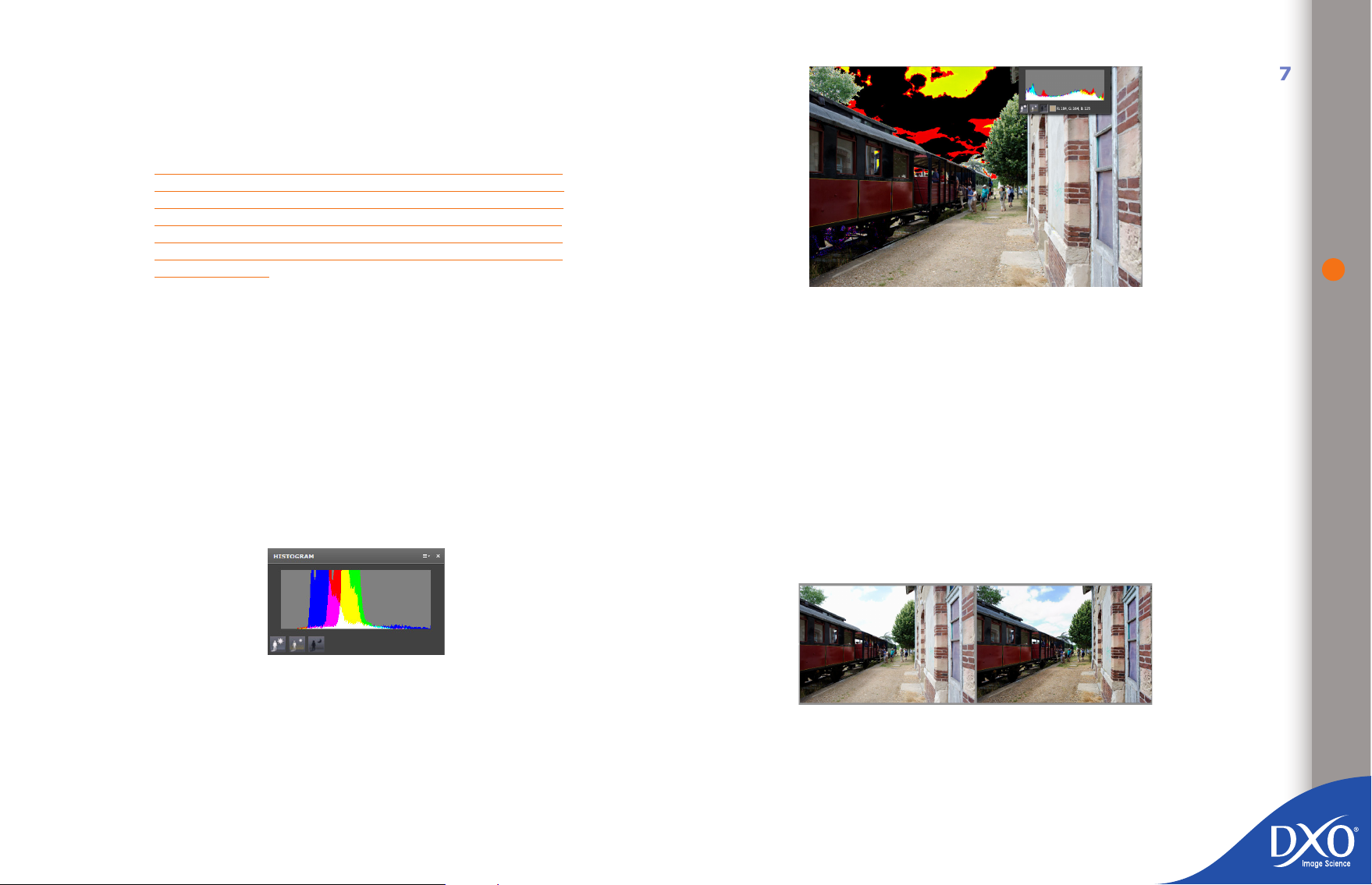
A dropdown arrow that allows you to choose from the predened zoom
8
7
6
5
4
3
toc12
•
factors or directly type in your own factor. To close the dropdown, simply
click again on the arrow.
Note that these commands are duplicated in the icon bar of the “IMAGE” pane
TIP: If you have a mouse with a thumbwheel, it will act as a
zoom in/out control, within the same limits as the standard
zoom controls. As you turn the thumbwheel you will see the
level of magnication increase on the scale. If you are planning
on producing an A3 enlargement (printout), then view at 75%
to get an accurate idea of the result. To see all details in full,
zoom in to 100%
27
4.5.1.2 Histogram palette
The histogram display is a graph showing the number of pixels for each tonal
value in the three color channels, with black on the left-hand side and white on
the right. You will nd it very helpful to keep the Histogram palette open while you
are working with the other tools, since it will give you a good idea of exactly how
each adjustment is affecting your image. Generally, we may consider that for a
properly exposed image – except for subjects that are naturally very dark or very
light – the values ought to be distributed across the full width of the histogram.
When adjusting exposure compensation or color balance, it can be helpful to
display the clipped areas (i.e. whites that are too transparent or blacks that
are totally opaque) directly in the image itself, using the buttons beneath the
histogram display.
Representation of highlight areas
These displays are intended to give a temporary pictorial indication of those
parts of an image that are “clipped” (i.e. dark areas that have reached minimum
black level or light areas that have reached maximum white level). Clicking on
the “Highlight clipping” button will display an image where small areas show up
black (= highlights where all three color channels are at maximum) or in other
colors (= only one or two of the color channels are at maximum).
The reverse happens for the “Shadow clipping” button: in this case, the picture
displayed has small white or colored areas that indicate clipping. The middle
button (“No clipping”) restores the normal display.
Using the highlight clipping display allows you to make very ne adjustments
when performing highlight recovery on a RAW le (see chapter 4.5.2.1): all you
have to do is move the manual slider slowly until there are no more clipped areas
visible.
Top, moderate highlight recovery. Below, stronger highlight recovery.
Page 28

you if any EXIF data is missing, which might mean that some optical defects
8
7
6
5
4
3
toc12
are only partially corrected. It shows the size of the image, exposure, the date
the shot was taken, focal length, ISO speed rating, whether ash was used, the
aperture, and the lens used.
The EXIF Editor allows you to add Author and Copyright information to the image
metadata section.
28
For lowlights, the display lets you see the exact effect of DxO Lighting, tone curve
or the brightness and contrast controls on any type of le.
To the right of these three icons there is a control line that only appears when
you move your mouse pointer over your image: this shows the color at the cursor
and its Red, Green and Blue (RGB) values in a small box.
Display of RGB values
4.5.1.3 EXIF palette
4.5.2 Correction palettes
All the correction options available in DxO Optics in the “Advanced user” works-
pace are controlled via ve palettes; the rst of these, “Tools”, provides shortcuts
to certain tools on other palettes. Each of the other palettes considers the image
in a “photographic” way. “Light” covers everything about lighting and contrast
in the scene; “Color” allows every possible chromatic modication. “Geometry”
is all about the global structure of the image, whilst “Detail” goes right down to
pixel level to deal with sharpness and digital noise control.
NOTE: Certain functions will only be enabled if the correction
module for the lens concerned is available. When this is not
the case, certain corrections will appear disabled and others
will only be congurable for manual adjustment. By the same
token, highlight recovery correction and precise white balance
to °K accuracy can only be applied to RAW les, in which case
additional controls appear.
Lastly, certain silver halide-type grain and color rendering options are only available if you have installed the optional “DxO FilmPack” module. Hence certain
screenshots in this chapter illustrate the most complete version of DxO 6, including these optional features.
4.5.2.1 Light palette
The EXIF information palette consists of two parts:
Image properties
•
EXIF Editor
•
The rst shows certain EXIF information written by your camera into the header
of the current image. This information cannot be altered and is saved when you
create a corrected copy of your image. It is an important reference and can tell
Natural scenes rarely exhibit ideal lighting conditions. Light sources are often
directional and sometimes quite harsh. What’s more, when shooting, we often
tend to concentrate rst and foremost on capturing just the right moment,
without always paying great attention to potential lighting problems. To compound the issue, the dynamic range of camera sensors is simply unable to
Page 29

compete with what our eyes can see. All this can result in some shots exhibiting
8
7
6
5
4
3
toc12
under-exposed, dark or shadowed regions with missing or muddied details.
ble via the three buttons beneath the Histogram display (see
chapter 4.5.1).
29
To a certain extent, such as when the wanted image signal is sufciently above
the noise level of the sensor, lighting problems can be corrected in post-production as long as appropriate image processing is available.
The “Light” palette gives access to all the controls relating to these issues. It has
been organized into four rollups:
Exposure Compensation
•
DxO Lighting
•
Vignetting
•
Tone Curve
•
Exposure Compensation
This involves overall control of the image exposure level (note that RAW images
offer much greater scope for correction).
The “Correction” menu is only active when a RAW le is being processed and
offers you a list of predened automatic exposures prioritizing either the main
subject or highlights.
Centered average measurement optimizes the measurement for the cen-
•
tral subject of the image
Auto-priority highlights offers slight, medium and strong options for
•
highlight recovery
In these exposure modes the exposure slider is positioned automatically. It can
also be positioned manually:
moving the slider to the right (or entering a positive Ev number in the
•
edit box) increases the image exposure,
Choosing one of the automatic exposure options can speed up your workow by
providing additional custom settings for this type of shooting situation: usually,
“slight” correction is enough for a normally contrasted image. Note that shadows
will be automatically compensated when adjusting highlights, as long as the DxO
Lighting control (see below) is active at the same time.
Highlight recovery is thus not activated by default, but it is exceptionally efcient at nding average values in skies that appear too white; sometimes the
ground may then appear too dark, at which point DxO Lighting must be adjusted
manually beyond its default value.
DxO Lighting
DxO Lighting is a “pixel-precise” image segmentation algorithm that provides
automatic local contrast adjustment, thereby revealing hidden detail in dark
areas. Simply put, DxO Lighting rst breaks down the image into a number of
zones in which luminance values have a certain range. It then processes each of
these areas in the most effective manner possible to reveal lost detail. In general
terms, brightness and tone curve slope are increased slightly in dark areas to
bring out detail, while avoiding the signal clipping that can occur if the overall
gamma level of the image is adjusted.
The main parameter involves choosing one of the three adjustment options:
Slight (standard choice in default conguration)
•
Medium
•
Strong
•
Then the intensity slider makes it possible to modulate how the chosen correction
is applied, by a factor between 0 and 150%. A text box lets you type correction
values in directly. You’ll nd a “magic wand” check-box to the right of the slider:
if you check this, an automatic value is applied by the program. Checking this
box also lets you revert to the initial values if you have gone a bit too far with
your corrections.
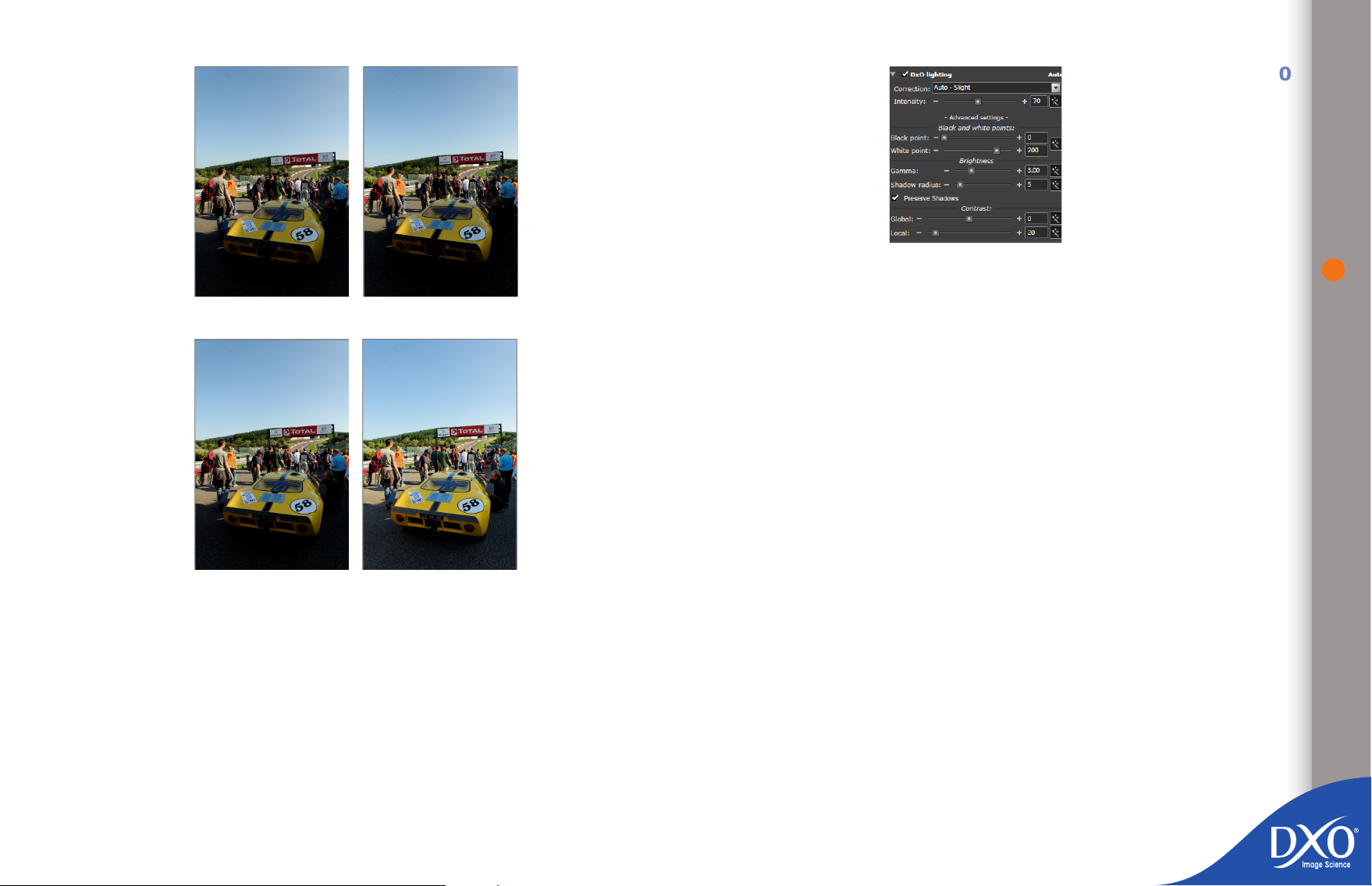
To see the actual effect, look at the four pictures below:
moving the slider to the left (or entering a negative Ev number) reduces
•
it. The range is from + 4.00 Ev to - 4.00 Ev.
TIP: When you are making exposure adjustments, you will nd
it helpful to use the highlight / shadow clipping display availa-
Page 30
DxO Lighting advanced settings
8
7
6
5
4
3
toc12
30
As shot DxO Lighting “Slight”
DxO Lighting “Medium” DxO Lighting “Strong”
In the above examples, you can see that a certain amount of detail has been
revealed in shadows, but the highlight areas have been preserved.
Below the Auto Mode dropdown menu there is a dialogue box called “+ Advanced
settings +”. If you click on this, an additional correction panel is displayed. Click
on “– Advanced settings –” to hide this panel.
The “Black point” and “White point” sliders operate in a complementary
fashion. Each has a range from 0 to 255, or you can enter a whole number in
the edit boxes instead. These controls have the effect of stretching the image’s
lower tonal range up towards white or stretching the upper range down towards
black. This is similar in many ways to what might be achieved using a tone curve
adjustment and is probably easiest to visualize in conjunction with the Histogram
display. The “Magic wand” button activates the automatic settings.
The Brightness adjustment basically acts like an overall gamma control, with the
slider and entry box having a range from 0.10 to 10.00. The “Preserve Shadows”
feature (checked by default) operates at high positive gamma settings, to avoid
“washed-out” shadows; the program decides to what extent the darker tones
should be “held back” as shadows.
The “Shadow radius” slider / edit box affects the way DxO Lighting makes its
decisions about which areas represent shadow or not, and how to apply the
gamma locally in the image. This slider has a range from 0 (entirely global) to
15 (fully localized): these arbitrary levels act differently according to the size
of the image. By default, the “Preserve Shadows” control is checked to avoid
unnatural effects such as a shaded area being lighter than a semi-tinted area.
As with other controls, there is a check box to the right of the adjustments that
allows you to enable auto-mode or revert to your initial settings after over-zealous correction.
Lastly comes the pair of sliders / edit boxes for Local Contrast (range from 0
to 200%) and Global Contrast (range from +50 to −50%). The Global Contrast
control uses a tonal S-curve to affect the overall contrast of the image, with a
useful level adjustment to enhance contrast in slightly at images and reduce
it in more highly contrasting ones – but be careful not to use this control at the
same time as the tone curve (chapter 4.5.2.1). The Local Contrast control, on
the other hand, is more subtle in its effect, altering the contrast in a spatially
determined way that takes into account the area around each pixel; this gives
a similar result to sharpening but in a subtler way, bringing out detail without
Page 31
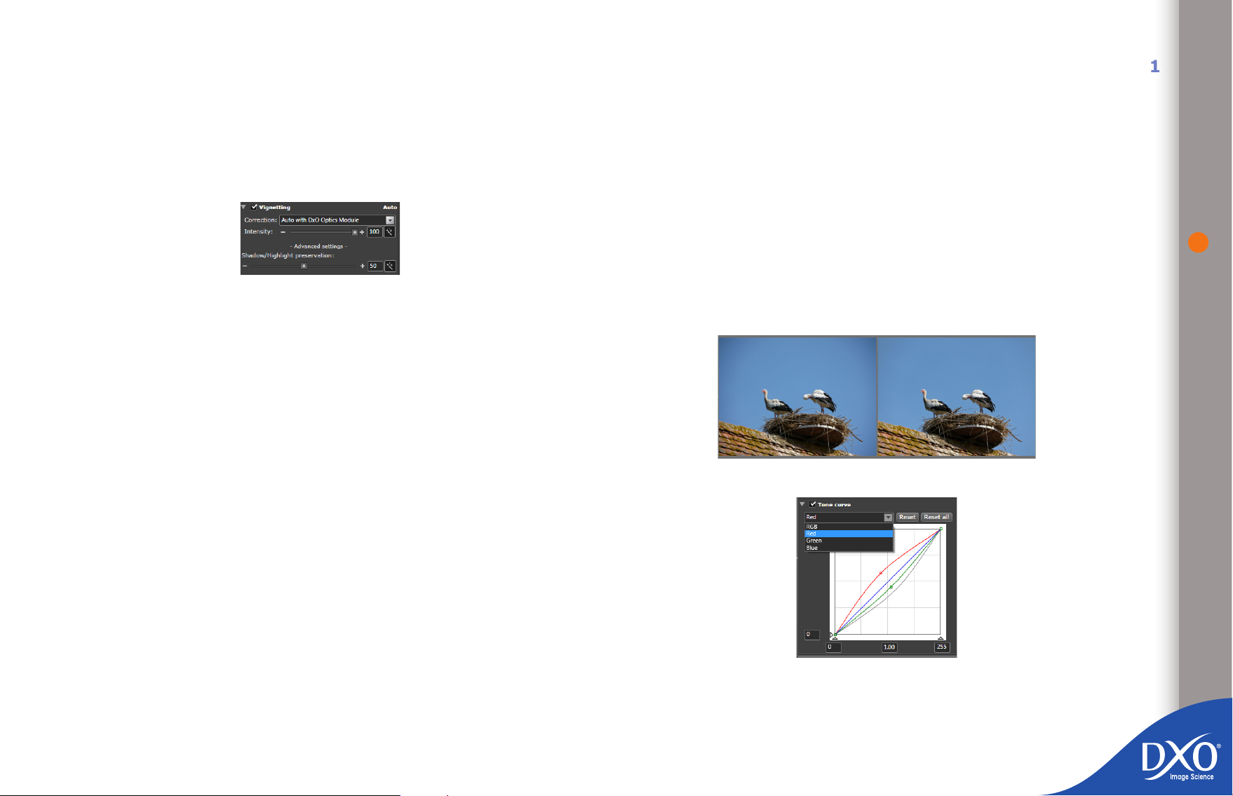
inserting additional black or white pixels. Take care, however, not to use a large
8
7
6
5
4
3
toc12
increase in local contrast with too much Unsharp Mask (chapter 4.5.2.4). To see
the effect of the correction for yourself, zoom in to 100% on a part of the picture
with some signicant small details.
Vignetting
Vignetting correction functions differently and uses separate commands depending
on whether or not you have a DxO Optics Module installed on your system.
In the case of automatic correction the DxO correction module type appears
by default when you open the dialogue box; but it is also possible to operate in
manual mode.
Vignetting correction takes place in two steps, both of which can be ne-
tuned.
First, from the lens data, focal length and aperture setting, the DxO
•
correction module computes the attenuation factor for every pixel in
the image, and each pixel’s RGB value is multiplied by the inverse of
this factor. The “Correction Intensity” slider (range 0 to 100%) allows
you to decide how much of the vignetting should be removed from the
image.
Second, a lter is applied to avoid clipping in bright areas and noise
•
increase in dark areas. This is achieved by limiting the value by which
a pixel can be multiplied, according to its luminance. The effect of this
lter will vary according to image content.
The range of this slider is 0 to 100%. The magic wand button allows you to revert
to the automatic setting.
Note: We recommend you do not depart from the default 100%, as the shadow preservation slider is often more effective than the intensity slider in preventing undesirable
vignetting correction side-effects. Also, only vignetting caused by the lens or sensor is
corrected. Mechanical vignetting, caused for example by too narrow a lens shade, cannot
be corrected. In the case of mechanical vignetting, you will want to use the crop tool to
remove the unwanted parts of your picture.
If you do not have a DxO Optics Module, you will see the manual correction
dialogue box appear. You can also opt for manual correction even if do have an
Optics Module but do not want to use the automatic settings.
Intensity is then graduated from zero and allows you to adjust by eye the level
of lightening you want in the corners of the image. From “+ Advanced settings
+” “Mid-eld amplication” you can select the area to which the correction will
be applied from the centre of the image. Be careful not to apply over-zealous
correction: the corners of the image should not be lighter than the centre!
Tone Curve
31
Clicking the “+ Advanced settings +” box gives you access to Shadow / Highlight
preservation, which restricts the amount of exposure correction applied by the
vignetting corrector at each end of the tonal range, so as to avoid either crushing
the shadows or clipping the highlights. For example: if you want to limit the
luminance increase (which may reveal unwanted noise) in dark image corners
because you shot at a high ISO, shadow preservation limits the degree of correction applied. Likewise, because of vignetting, the camera may have incorrectly
exposed a cloud in the sky. The highlight preservation lter allows you to apply
as much vignetting correction as you want, while still retaining wanted highlight
detail.
The tone curve is a very standard and very powerful tool, available in many
image processing applications, but it is not easy to master at rst. We recommend you do some tests, to see if you prefer working with the curves, or can
Page 32

achieve similar results using DxO Lighting (chapter 4.5.2.1) or the HSL dialogue
8
7
6
5
4
3
toc12
box (chapter 4.5.2.1).
The tone curve shows the relationship between tonal values into the tool (across
the x axis) and out of it (up the y axis). The tone curve represents the transfer
characteristic, or the way in which input tones are mapped onto output tones:
for example, a mid gray in the original le might appear lighter or darker in the
output after processing, as might colors, since each Red, Green and Blue layer
can be corrected independently. Conversely, the initial straight line indicates
that the output tonal values are exactly the same as the input values over the
entire tonal range.
The input and output black and white points can likewise be set, either by dragging and dropping the relevant points with your mouse, or entering numerical
values in the four entry boxes, from 0 (black) to 255 (white).
32
In order to adjust tone mapping for correction or creative purposes, the straight
line is manipulated so as to alter this input/output relationship. In traditional
photographic terms, this means altering the gamma of the image, and this gra-
phical approach allows for a great deal of exibility.
Note that the combo box at the top lets you choose to adjust either the Master
channel – i.e. all three colors together – or any of the three channels individually.
The buttons to the right enable you to reset either the single curve you are working on, or reset all three of them together back to the default straight line.
To control the various zones of the image (light, medium or dark tones), all you
have to do is left-click on the line to add points to it.
Note: it may take a bit of practice to click exactly on the point on the line you want to
adjust.
As soon as a point is created, it is “locked”. By holding your mouse button down
and moving the point you can drag the line around, creating a curve as you do
so. You can watch the results of your adjustments in real time on the preview
image. One very simple processing option involves moving a point located at
the top of the curve (in the highlights) above the diagonal and moving a point
located at the bottom of the curve (in the shadows) below the curve: this creates
an S-curve, hence the name given to it in all the post-processing literature, and
allows you to achieve more marked contrasts.
You can create as many points as you need in order to generate the curve you
want. To move a point, simply click on it and drag it to a new location. The active
point is shown lled in black, and inactive ones as hollow white. Likewise, you
can delete the active point using the Delete key.
An alternative to drawing a made-to-measure line is to make a numerical entry
of the gamma value. The box at the bottom center is set by default to a gamma
of 1.00, but you can enter any gure between 0.05 and 6.00. A gamma value
higher than 1 tends to bring detail up out of the shadows, whilst a value lower
than 1 pushes detail down into the blacks.
An S-curve, so called because of its shape, makes the image contrasty and ‘punchy’
4.5.2.2 Color Palette
White Balance
The light that is used to take a shot seems white to us, but it’s often yellowish (domestic
incandescent) or bluish (twilight shadows): the human eye corrects the balance, and digital
cameras try to do so automatically. But if the correction isn’t perfect, it’s possible to correct
the image so that an area we know is white or neutral regains its natural appearance.
It’s worth noting that the corrections will be more accurate from a photo in RAW format,
though the so-called “color picker” method usually yields good results on all types of les.
Note that the color picker is available from the White Balance control on the Color palette,
and also from the “Tools” palette with the same basic functions.
White Balance using the color picker
The color picker lets you dene a color on the image to be reproduced as neutral
gray, with no predominant color.
NOTE: The point chosen as the white reference should be a fairly
light gray tone. Avoid very bright highlights that seem transpa-
rent on the screen, because the results can be unpredictable!
Clicking on the color picker will display two preview images side-by-side, the
left-hand image being the original and the right-hand image showing the effect
of adjusting the white balance according to the reference point chosen. If you
Page 33

have already chosen to have a side-by-side display for all your corrections, the
8
7
6
5
4
3
toc12
original image will be active for clicking a point with the color picker. A message
will appear in the upper left section of the original image instructing you to “Click
a point in the image to neutralize its color.”
Simply position your mouse pointer over the required area (you can zoom in to
make it easier to select the point precisely) and left-click to balance the whites
at this point. At any time, you can re-select “As Shot” (in the dropdown menu
of the “White Balance” rollup) in order to cancel the changes and go back to the
original white balance setting.
Tip: The ‘Radius’ slider at the bottom of the “IMAGE” pane lets you set the size of
the sample zone to be neutralized. In the case of images at high ISO settings, we
recommend increasing the ‘radius’ slider setting to 10, to reduce pointing errors.
White Balance using the dialogue box for a RAW le
In the “Settings” dropdown menu there is a list of settings corresponding to
those that are most frequently found on digital cameras: daylight, cloudy, sha-
dow, tungsten, uorescent, etc. The “As Shot” line corresponds to the settings
in the le’s EXIF data.
If you click on “+Advanced settings+” you can also select a precise level of color
temperature and then ne-time the image’s dominant tint. You can select a
base value in °K (used for measuring color temperature), for example 3,200 for
articial lighting, 2,800 for warm domestic lighting, 5,400 for sunlight or ash,
6,500 for cloudy daylight, etc. Select “As Shot” again from the “Settings” menu
to revert to the automatic settings.
White Balance using the dialogue box for a JPEG or TIFF le
A single temperature slider appears when the advanced settings are activated
so that you can make ne adjustments to the average color temperature on the
blue-yellow axis.
EXAMPLE: Imagine that a picture has been taken under tungsten articial light, but with
the camera accidentally set to “daylight”. The resulting image will appear too orange.
Moving the slider to the left, towards a lower K value, will be more appropriate for the
articial light actually used and will cool the image, therefore correcting the orange cast.
EXAMPLE: Here in the middle is the picture as shot, and to the left and right, the effects
of shifting the color temperature slider left and right respectively.
Vibrancy
The Vibrancy tool is a “smart” color saturation slider.
When the slider has a positive value, Vibrancy acts to:
saturate all colors
•
saturate esh tones less
•
saturate sky tones more, and darken them slightly, to give them greater
•
depth
preserve areas that are already close to gray so as not to provoke a
•
change of color balance.
Vibrancy is adjusted using a single slider, which can also take negative values,
producing different effects on the image:
overall desaturation of colors, but never total (unlike the HSL control,
•
where a saturation of zero makes the image B&W)
more rapid desaturation in the reds, which is useful for ‘rescuing’ photos
•
where the faces are too red and making esh tones more natural.
Be careful not to combine excessive vibrancy correction with too high a level of
saturation in the “Color rendering” dialogue box.
33
Page 34
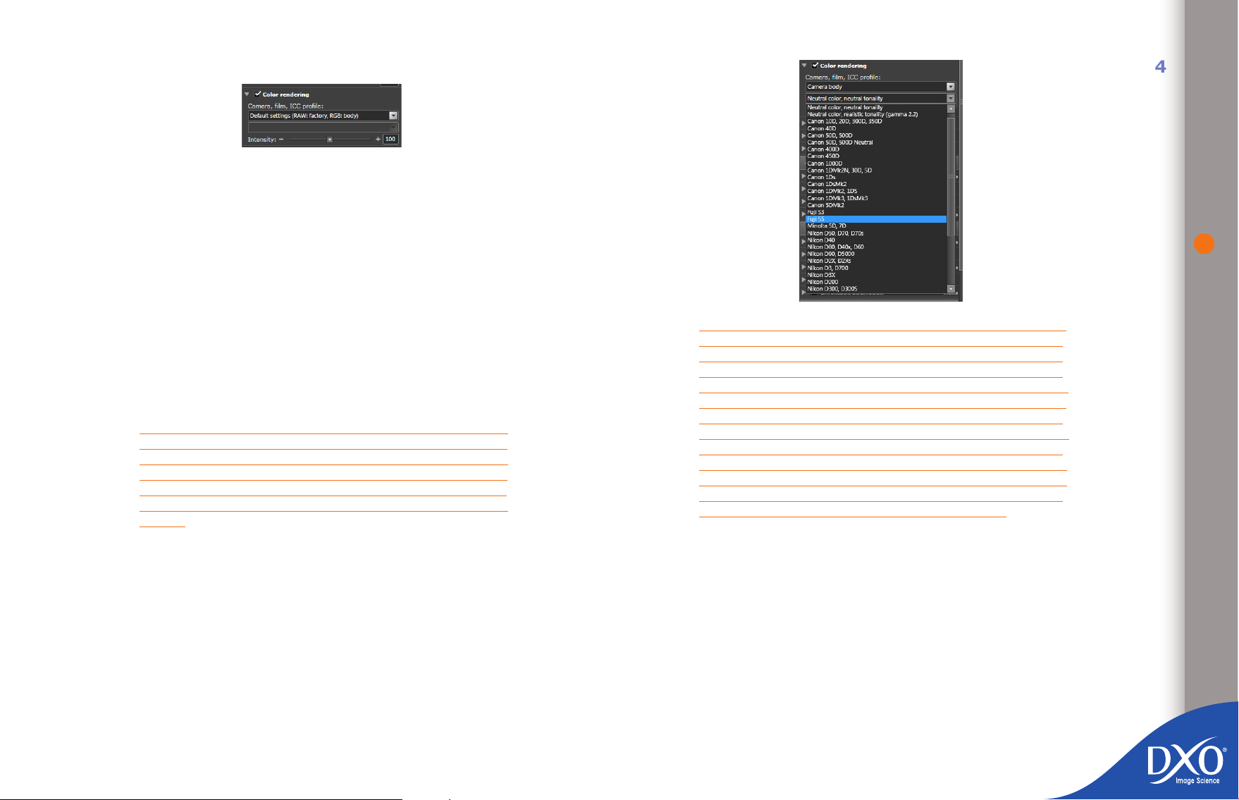
Color rendering
8
7
6
5
4
3
toc12
The Color rendering rollup lets you vary the colors compared with the original
image. The rendering is different depending on whether the image was shot in
RGB or RAW:
in RGB (camera original JPEG or TIFF), the rendering is that produced by
•
the camera and its own specic settings; this rendering may be different
depending on whether you have shot in a style such as “landscape”,
“portrait” or even “B&W”, for example.
The color rendering dialogue box also gives you access to silver halide-
type lms and all traditional-style lm modules if you have loaded the
optional DxO FilmPack module into DxO Optics Pro; otherwise, simply
leave this unchecked.
in RAW, the basic rendering is the one measured by DxO for a “standard”
•
or “normal” camera setting – we’ll refer to this as the “factory” setting
as it’s the one preselected on the camera as supplied.
TIP: The default rendering in DxO Optics Pro tries to replicate
the color rendering that the camera would have generated on a
JPEG image, which in general is quite saturated and contrasty.
The “Camera” / “Color neutral, tonality neutral” color rendering
will produce a more neutral image with a lower level of contrast.
(This color rendering is also accessible via the “Natural Color”
preset).
In RAW, it is also possible to apply the color rendering of
– another camera: e.g. for a reportage shot using both a Canon and a
Nikon, where you want the images to match, or to give your images
a specic “look” based on the styles specic to certain cameras
– silver halide-type lms This functionality will give you access to a wide
range of lm proles if you have activated DxO FilmPack.
– a particular ICC prole (see below for more detail)
The intensity slider lets you dene the mix between the original prole and custom prole; the normal value is 100.
34
NOTE: For a RAW le, the intensity slider lets you mix between
the neutral color rendering and the selected color rendering pro-
le (another camera, a silver-halide prole or an ICC prole):
• at 100, this slider gives the selected color rendering
• at 0, this slider gives a neutral rendering, which is not the
same as the “As Shot” rendering; this provides a base for more
personal renderings
• from 0 to 100, you move gradually from the neutral color
rendering to the color rendering selected
• above 100, a color rendering is applied that exaggerates the
tendencies of the selected color rendering. Take care not to go
too far with this slider!
• mixing is not possible when an ICC prole is used.
For an RGB input image (JPEG or TIFF) the slider mixes between the original
image and the rendering selected.
The “ICC prole” option allows you to load a specic prole created from a test
image in order to provide a fully customized color rendering.
All you have to do to import an ICC prole is to open the dialogue box by clicking
on “ICC prole” and then click the les you want. You can download this type
of prole from the Internet or have one created (after exporting a test image:
see the “File” menu). Once a prole is loaded it will appear directly in the list of
available settings.
NOTE: This function and that of choosing the color rendering from another digital camera
are not compatible with JPEG les
Page 35

Color modes
8
7
6
5
4
3
toc12
This rollup gives you access to basic quick global contrast and saturation settings,
which may remain at 0 if, for example, you have already optimized these values
with DxO Lighting, the Tone Curve or Vibrancy and to styles you can apply to
your photos immediately:
As Shot (default value)
•
Landscape
•
Portrait
•
B&W
•
Sepia toning
•
If the optional DxO FilmPack module has been activated, you can also select
effects lters for B&W and toning styles that reproduce the effects of chemical
treatments on paper prints.
The “Contrast” slider lets you adjust the overall contrast of the image.
The “Saturation” slider lets you move from black and white (−100) to highly
saturated colors (+100).
HSL (Hue / Saturation / Lightness)
This rollup gives you very ne adjustment of hue, saturation and lightness, either
for the master channel, or independently for each of the three primary (Red,
Green, Blue) and three secondary (Yellow, Cyan, Magenta) color axes.
These settings allow you to make very ne adjustments, because the Hue slider
can be moved to the left or right, or a positive or negative gure can be entered
in the edit box. The exact effect of this slider is naturally affected by which color
channel(s) you have selected to adjust. The slider and box values range from
+180 to −180. This is a very powerful correction, because you can move the red
hues in an image towards green or blue without the grays being affected!
35
Example of HSL on red
For Saturation, the slider can be moved to the right to increase, or to the left
to decrease, the color saturation (overall or on any one or more of the six color
axes), or a positive or negative gure can be entered. The slider and box values
range from +100 to −100.
The same goes for the Lightness slider. Move the slider to the right (or enter a
positive gure) to lighten and to the left (or enter a negative gure) to darken.
The slider and box values range from +100 to −100.
The action of the Lightness slider is interesting and easy to understand if you
look at the results of the changes on the Histogram display. Moving the slider to
the right or entering a positive gure lifts the black level towards white, compressing the tonal range into the upper half of the scale. Conversely, moving
the slider to the left or entering a negative number brings the white level down
towards black, compressing the tonal range into the lower half of the scale. The
“As Shot” button cancels any HSL correction. The same applies if you uncheck
the correction on the Color palette.
NOTE: If you want to correct several colors at the same time,
we suggest you have something to hand with which you can
take notes on the correction values used for each color layer so
that you can ne-tune a particular correction without having to
start over again: moving a color just a few points can have a
signicant effect!
Multi-point color balance (MPCB)
Multi-point color balance is a hybrid tool that makes it possible to make ne
adjustments to an image’s neutrality following an initial color balance, or to
modify one color for creative purposes whilst preserving the variations of the
other colors. It can also be used to radically change four different colors in the
image – but in that case the results risk departing a long way from a natural
look.
To transform a color, you click on the multi-point balance icon, which will display
two thumbnails. In the left-hand image you select a colored area of the image
and a color wheel is superimposed on it, with a radial line across it that controls
Page 36
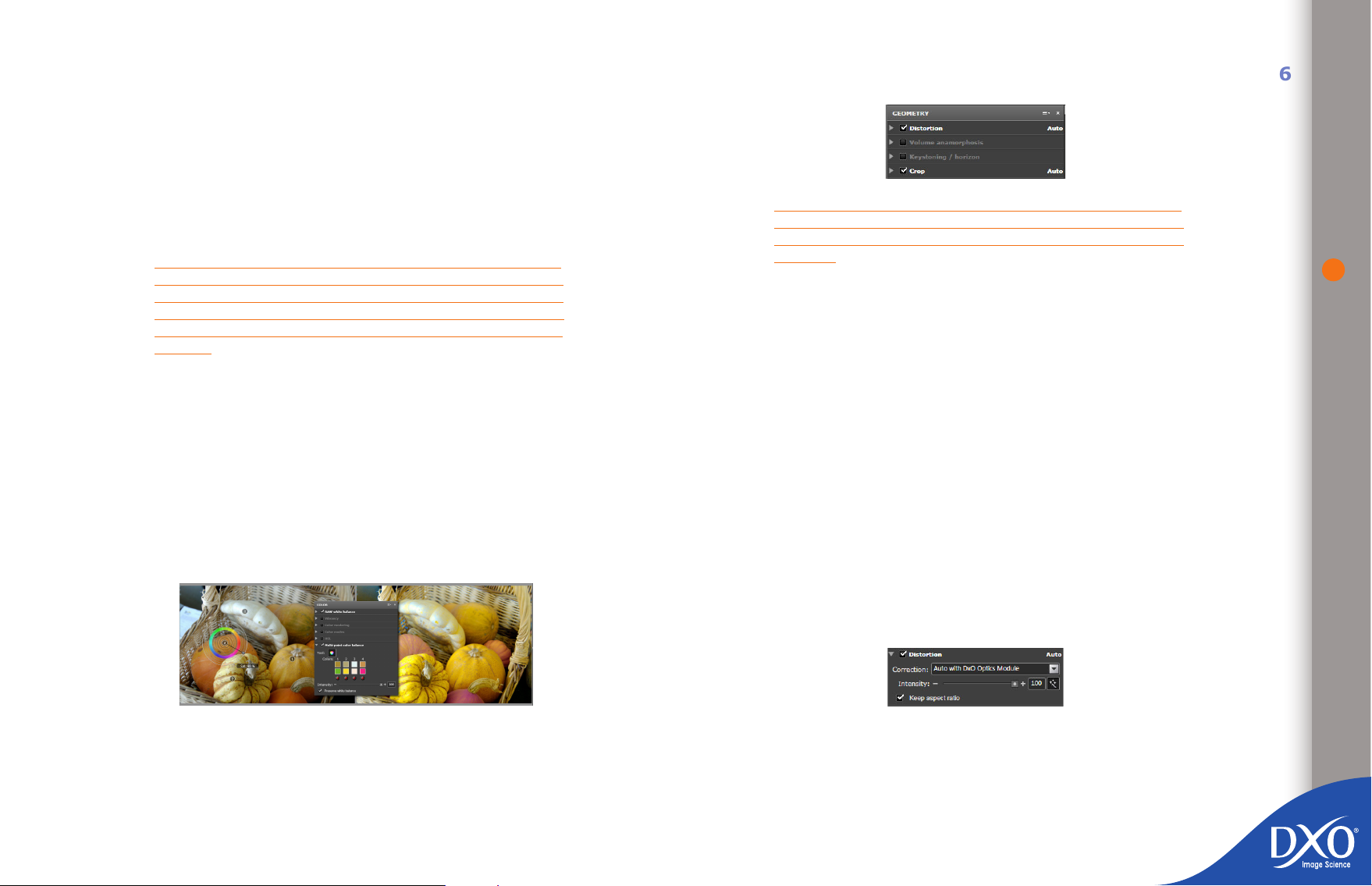
the saturation. The hue is changed by turning the wheel, adjusting the saturation
chap10-exif
8
7
6
5
4
3
toc12
of the selected color.
You can temporarily lock the hue by holding down the Ctrl key as you drag the
pointer with the mouse, or the saturation by holding down the Shift key. Hue or
saturation can also be locked by right-clicking on the color wheel and selecting
one of these two options.
4.5.2.3 Geometry Palette
36
This control can be applied to up to four colors in the image, but if you only want
to change one color, it can be effective to click on adjacent colors to protect them
from being affected.
TIP: You might want to zoom in to a specic part of your image
to make choosing the exact color point easier. You can zoom
after you have clicked on the MPCB icon. Use the “hand” tool
to move around and display different portions of the image.
One good way to try out this tool and learn how to use it is on
blue sky.
The dialogue box displays the original color and the substitution color, whilst the
color to be retained for processing can be checked by using the Xs below the
two color swatches (“before” at the top and “after” at the bottom). A color can
be re-adjusted at any time by clicking in the centre of the selection point in the
left-hand image.
The “Radius” slider alters the size of the zone used to calculate the color associated
with the color wheel center position (to avoid highly local color variations, such as
noise). The “Intensity” slider lets you moderate the transformation applied to the
image (a blend between the “identity” correction and the calculated correction).
The “Preserve White Balance” command makes it possible to preserve gray tones
(checked by default, as it helps to stabilize the result slightly).
NOTE: if the correction module for the lens you used to shoot
the current image is not loaded onto your system, some or
all of these corrections will be disabled or have to be made
manually.
The Geometry palette has been organized into ve rollups, the rst of which only
appears where needed to clarify the information in the EXIF data:
Focal length (only shown where this information is incomplete in the
•
EXIF data)
Distortion
•
Volume anamorphosis
•
Keystoning / horizon
•
Crop
•
Focal length
The focal length of a shot is recorded in the images EXIF data. However, it can
happen that this information is not recorded accurately enough (several positions of the focal length ring giving the same value in the EXIF). In this event,
if you are not satised with the default distortion correction proposed, a slider
is available that lets you set the focal length exactly, so you can ne-tune the
distortion correction manually.
Distortion
The geometric distortion introduced by a lens may be pincushion, barrel – or even
sometimes a mixture of the two. In each case, the analytical measurements carried out by DxO Labs make it possible to correct the distortion in such a way that
the straight lines in the original scene are correctly reproduced as straight lines
in the photo. The Distortion tool has just one slider for the degree of distortion
correction, with a range from 0 to 100%. The default setting is 100%, and you
Page 37
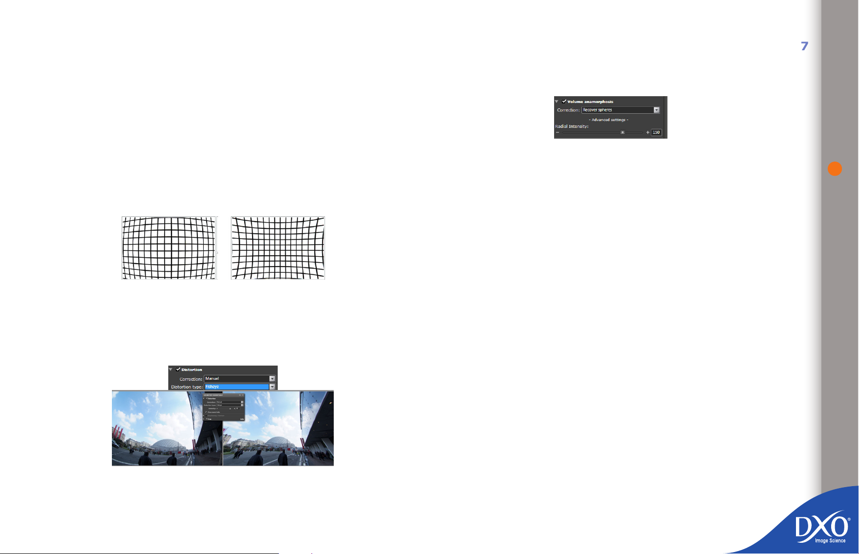
should only depart from this in special circumstances – either to avoid cropping
8
7
6
5
4
3
toc12
of important detail near edges, or for creative reasons.
The “Correction” dropdown menu allows you to select automatic correction based
on a DxO Optics Module or manual correction. Only the manual option will be
active if you do not have a DxO Optics Module.
If you are working with manual correction, you will need to select the type of
distortion:
Fisheye, for lenses that produce a rounding effect on the whole image
•
eld
Barrel, when the distortion at the top or bottom of the image is rounded,
•
and the curve is higher at the centre of the image than at the edges
Pincushion, when the distortion is the other way round
•
the aspect ratio, so the cropping is just the bare minimum required to straighten
out the edges of the image. You are then free to crop the image manually to
suit your needs.
Volume Anamorphosis correction
There is a fundamental problem when capturing a picture of our three-dimensional (3D) world onto a two-dimensional (2D) image, which is governed by the
basic laws of optics. When converted into a at image, the shapes of certain 3D
objects appear distorted, so they do not correspond to what our eyes and brain
expect to see. This is referred to as “volume anamorphosis” and is most noticeable and objectionable when using wide-angle lenses or when it affects foreground
objects close to the camera and near the edges of the image.
One of the biggest problems when trying to correct for this distortion is that it is
entirely picture-content dependent. And because of the trade-offs involved, how
much correction needs to be made is of necessity a subjective, artistic decision
that must be made by the user.
37
Barrel (left) and pincushion (right) distortion
If you are correcting an image with no DxO Optics module by eye, or you want
to ne-tune the results of automatic processing by making manual adjustments,
it is very helpful to display a grid overlay over the image by clicking the grid
overlay button to the left of the hand and magnifying glass icons in the icon bar
of the “IMAGE” pane.
There is a check box to enable or disable Keep Aspect Ratio. Normally, during
distortion correction, the corrected image is re-cropped back to the original
aspect ratio. However, in certain cases, this may means that the image is cropped
tighter than is strictly necessary. Disabling this option releases this constraint on
This deformation is most evident with 3D objects near the camera, and the correction required depends on their underlying shape. Basically cylindrical objects
(for example, columns or full-length human gures) need correction along one
axis more than another, which we refer to as cylindrical correction (in one direction only, either horizontal or vertical). Spherical objects (e.g. a human head)
need correction on both axes at once. We refer to this as spherical correction
and it is actually calculated along a radius from the center of the picture. Both
of these corrections are dependent on the focal length of the lens used to take
the particular picture.
The volume anamorphosis correction rollup contains a dropdown menu to select
either spherical or cylindrical correction and a Radial Intensity correction slider.
The slider takes values from 0 to 200% and allows you to control how much of
the selected correction is applied to this image.
To adjust this setting, you rst need to examine the image and decide what
sort of correction is required. Choose the appropriate type of correction for
the picture content that needs correcting, and then apply as little correction as
possible to render the residual distortion acceptable. Over-correction will start
to introduce unwanted geometric distortion and you may have to settle for the
best compromise. Using a grid overlay over the image to make your corrections
is also very helpful.
Page 38
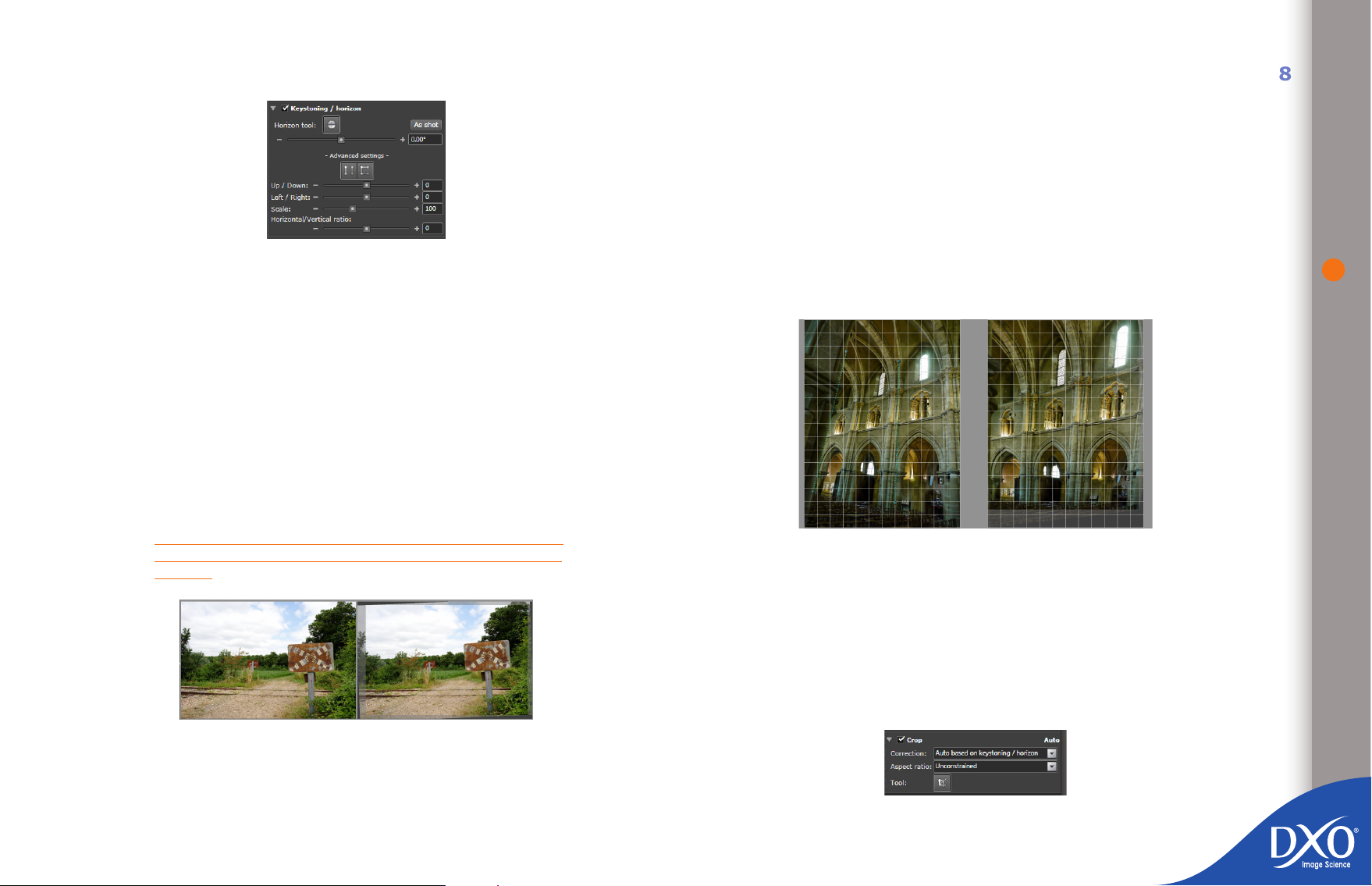
Keystoning / Horizon
8
7
6
5
4
3
toc12
Selecting the Horizon option (the line button above the slider for the Horizon
tool) lets you dene a line in the picture that you want to correct so as to be
horizontal (or vertical). To do this, you rst create one end point by clicking with
the mouse in the left-hand (preview) image, then hold down the left mouse button and drag the cursor to the other edge of the image. As soon as you release
the mouse button, a second point is set and denes your horizon line, which is
shown in bright green on the preview image.
The right-hand (“after”) image will rotate in such a way as to make your chosen
line horizontal (or vertical). If you make a mistake, you can click on Undo [Ctrl
+ Z] and then reset your second end-point. A slider and numeric entry box allow
you to make corrections to 1/100 of a degree.
The Horizon slider has a range from −180° to +180°, enabling the image to
be rotated completely upside-down at either extremity of the scale. This tool is
also useful for correcting leaning verticals.
At the top of the expanded rollup are buttons to control keystoning using either
parallels or a rectangle.
If you select Force Parallel, you will see two images displayed side-by-side; then
simply draw two lines (which you know were parallel in the original scene) on
the image to realign and reset the picture. The Rectangle tool can be used in
the same way to draw a box where you want each side to be parallel to the one
opposite.
Note: these commands can also be accessed via the shortcuts on the Tools menu
The pair of “Up/Down” and “Left/Right” sliders give you additional ne control for
adjusting vertical or horizontal keystoning correction, with both sliders having a
range of −125 to +125. Also note that you can type in a value instead of using
the sliders for even more precise control of these functions.
38
TIP: Using the “Toggle Grid Overlay” button in the middle of
the toolbar can help make it easier to adjust the squareness of
the shot.
Correcting horizontality
If you click on “+ Advanced Settings +”, the “Keystoning / Horizon” correction
rollup will expand to display additional button and slider controls.
The “Scale” slider lets you resize the image while maintaining all the proportions
associated with it. The default value is 100%, and you can reduce the size to
50% or increase it to 200%.
The “Horizontal / Vertical ratio” slider lets you stretch or squeeze the height of
your image while keeping the width unchanged. The scale runs from −100 to
+100, which represents from 50% to 200% of normal height. Using this tool will
change the visual proportions of the subjects in your picture.
Crop
Complex keystoning correction
Page 39
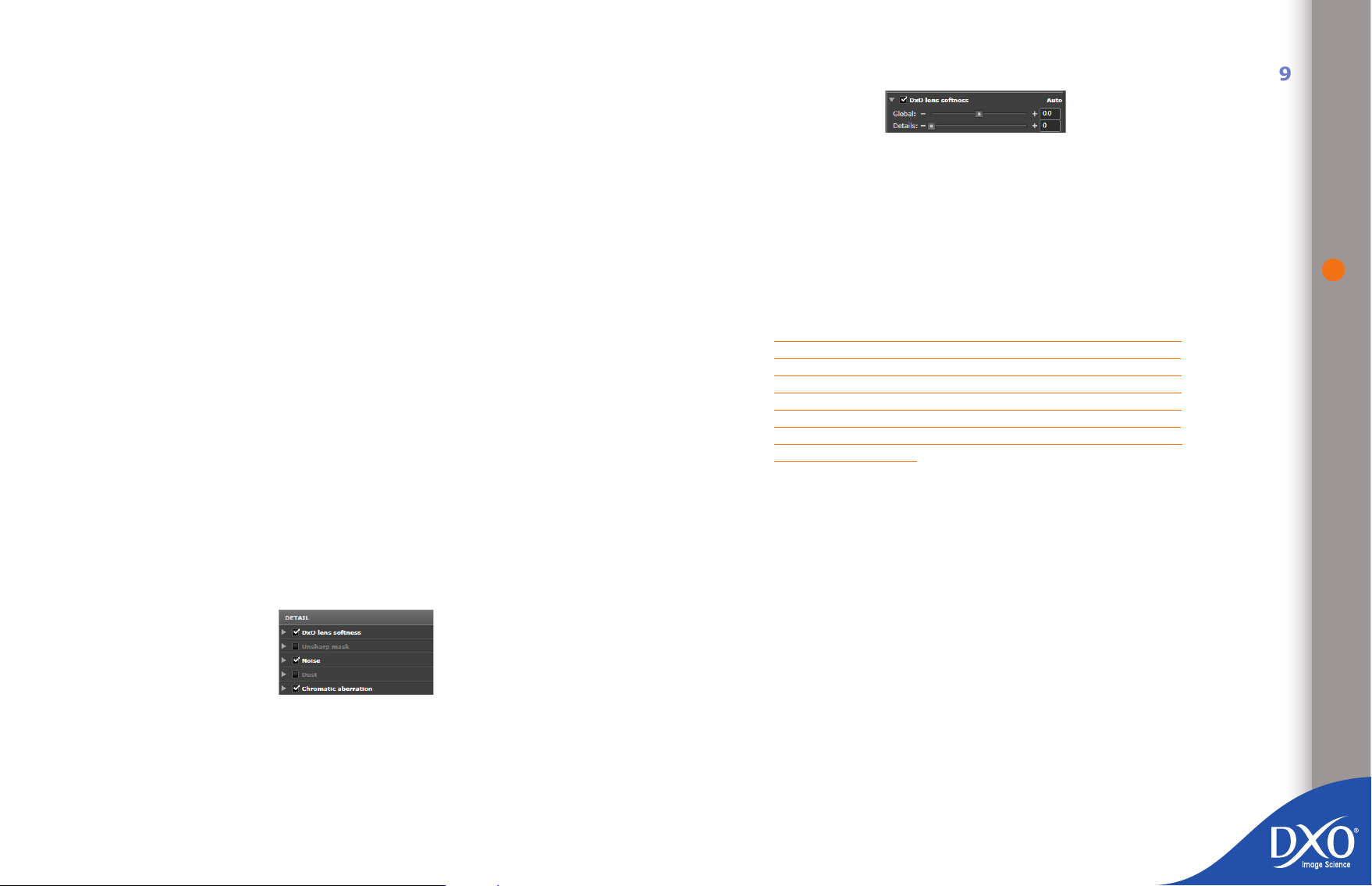
An image whose keystoning has been altered generally loses some information
8
7
6
5
4
3
toc12
at the edges – a great deal more if the correction is very signicant. By default,
the “Crop” box is set to “Auto” mode, and cropping is performed based on
the corrections under “Keystoning / Horizon”, and the aspect ratio defaults to
“Unconstrained”, so as to retain as much information as possible, though at the
expense of image proportions compared with the original image.
If you select the “Preserve aspect ratio” option the image will be resized so as to
retain its original aspect ratio, for example 3/2 or 4/3 (indicating the relationship
between the long and short sides).
You can add a custom ratio to the list of available ratios, for example 5/4 to
replicate the American 10” × 8” (25 × 20 cm) format or the classic 5 × 4 inch
results from traditional large-format cameras. A 1/1 ratio naturally implies a
square crop. Custom ratios can only consist of whole numbers separated by a
fraction bar.
If you select manual cropping, you will see a dotted crop box appear on the image
that you can move and resize using your mouse. The box will be in the shape of
the ratio you have chosen, e.g. square for a 1/1 ratio, or a rectangle of different
proportions for a 3/2, 2/3 ratio, etc. You can change the size of the crop box by
clicking on the squares in the corners with your mouse.
To adjust a crop you can also click on the Crop tool button. Once Crop has been
enabled, you can select a point in the image, hold down the left mouse button
and drag to create a resized crop box that appears as a black rectangular frame
within the image. By clicking on and dragging the corners of the rectangle you
can adjust the size of the crop. Clicking on the borders of the crop will allow you
to move the crop box and clicking on an area outside of the crop will remove the
crop box and allow you to create a new rectangle.
4.5.2.4 Detail palette
Lens softness
DxO Optics Pro can only correct for certain kinds of lens softness (lack of shar-
pness) – the inherent inability of the lens/camera combination to reproduce ne
detail (commonly referred to as “optical blur”). Other kinds of softness, caused
by inaccurate focusing, insufcient depth of eld or motion blur, for example,
cannot be corrected.
This forms part of the DxO Optics Pro optical corrections, and as such, is lensand-body dependent. As a result, this rollup will only be enabled for images for
which the appropriate DxO correction module is installed. There is a check box
to disable this correction.
NOTE: if you use RAW formats for your photos, the automatic
system is generally the best option, because it takes account of
the characteristics of both your lens and your sensor. For JPEG
images, however, it is important not to increase the sharpness
of a shot that has already been sharpened by the camera. Get
into the habit of not over-crispening your JPEG photos when you
intend to post-process them – for example by using a neutral
mode when shooting.
The “Global” slider allows you to manually set the overall level of sharpness required for a particular image. Remember that this tool tries to achieve a uniform
level of sharpness over the whole image, so it will automatically apply heavier
correction to the areas of your image where lens measurements are poorer. The
sharpness level you choose to apply will of course depend on your personal taste,
nal resolution and type of output (print, web, etc.)
The slider / edit box range is in units from −2.0 to +2.0 (from “Softer” to
“Sharper”), with a default setting of 0, which is the lens softness setting that
has been determined by DxO Optics Pro as the best setting for this particular
image.
39
Moving the slider to the left or entering a negative value will reduce the sharpening (but the image will never become softer than the original image). Moving
Note: The corrections in this palette will not be visible in the “Customize” tab below
75%, so when performing advanced corrections you may need to zoom in (the quickest
solution being to select the 100% option).
the slider to the right or entering a positive value will give a sharper image than
the correction obtained at the 0 position. The sharpening applied in DxO Optics
Pro is intelligent in that it depends on the image content. Areas with noise are
sharpened less than areas containing detail.
Page 40
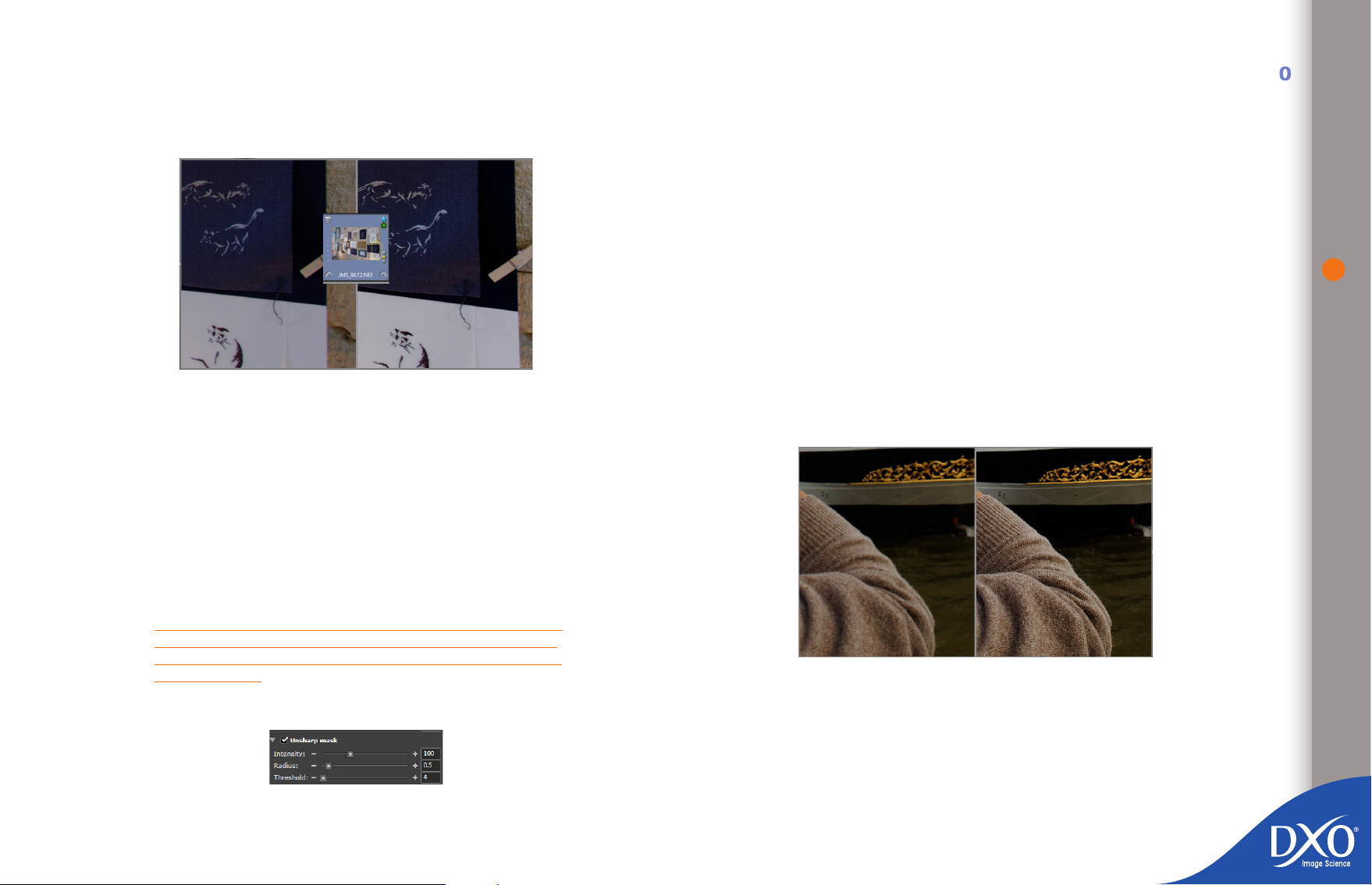
For each area in the image, the amount of sharpening will also depend, for
8
7
6
5
4
3
toc12
example, on the ISO settings used to take the picture. Less sharpening is automatically applied at a higher ISO than a lower ISO, to avoid increasing the noise
in the image.
Automatic lens softness optimization in a corner of the image (displayed at 100%)
The “Detail” slider is set at 0 by default and is used to make signicant adjustments to bring out the micro-contrast of ne details in the image, taking account
of the fact that it is often very rewarding to bring out ne detail in a landscape,
whilst emphasizing skin defects in a portrait is less desirable. Note that enhancing
details in this way does not create white edges around the areas treated, unlike
the “Unsharp Mask” option.
The “Unsharp Mask” rollup is disabled by default. It is usually only needed on
RAW les (where no DxO Optics Module is available), as JPEG les have been
crispened in the camera itself. For a RAW le with no DxO Optics module avai-
lable, it is often necessary to adjust it by eye (zooming in to view the image at
75% or 100%), using the following values as a starting point: intensity 100,
radius 0.5, threshold 4.
The Intensity slider / edit box sets the degree of sharpening correction applied,
with a range from −100 to 500 (negative values make the image softer whilst
positive values make it sharper). In practice, a value of 200 gives a very good
level of sharpness on a photo taken with a good lens. The Radius slider / edit
box has a range of units from 0.10 to 5.00. This control affects the neness of
the width of the correction zone surrounding image detail. Low values (lower than
1) will give very subtle correction, whilst over-use of high values can lead to the
formation of haloes. In practice it is unusual to have to go above 2.
The Threshold sets the amplitude (in terms of gray levels) of the transitions in
the image above which correction will occur. With the threshold set to 0, sharpening is applied to all transitions in the image, even the lower contrast ones (but
digital noise in particular is also emphasized). With a threshold of 255, there
would not be any sharpening. In practice, the threshold can be adjusted between
5 and 10 on a slightly burnt-out image.
40
It is therefore recommended that you perform as much of your sharpening as
possible using the Lens Softness correction before using the Unsharp Mask (USM)
which, although it is a sophisticated and adaptive tool, is a more generalized
process. Of course, for images where the appropriate DxO Optics Module is not
installed, all sharpening will have to be done using the USM.
TIP: if you often use lenses – for example, older models – for
which no DxO module exists, you can create a preset for yourself named after these lenses using the Unsharp Mask settings
described below.
Unsharp Mask
Manual crispening (displayed at 100%) for an older lens (1970) for which there is no DxO
Optics Module
Grain
This rollup only appears if the optional DxO FilmPack module has been
installed.
When the Grain box is checked and DxO FilmPack is installed, you can apply
the lm grain characteristics of several types of lm to your image. By clicking
on the dropdown box, you can choose to stay with the current color prole or
Page 41
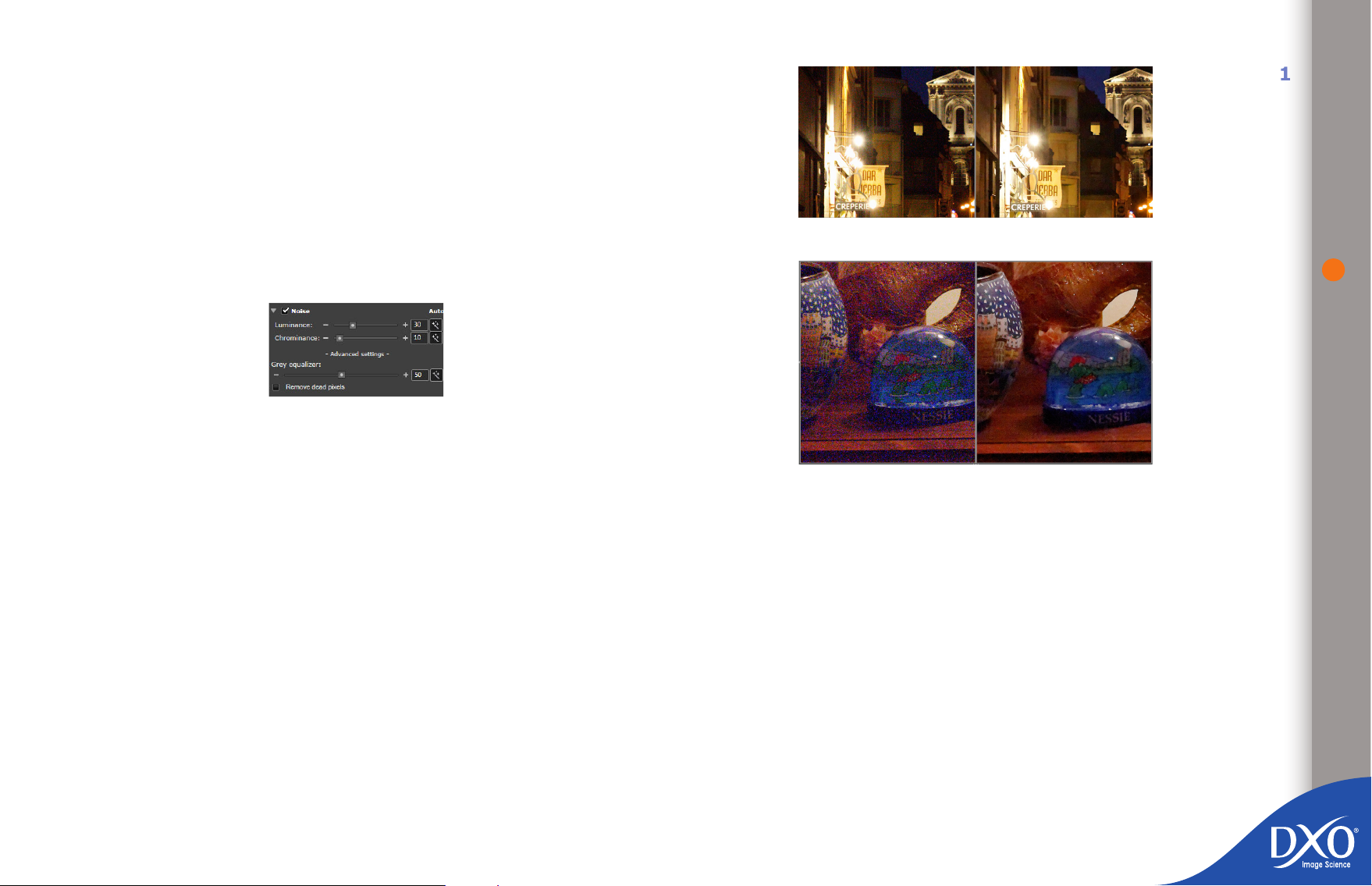
one of the lm proles provided. The slider below the dropdown box allows you
8
7
6
5
4
3
toc12
to adjust the intensity of this effect. There is also a direct entry box so you can
specify the intensity you want, from 0 to 100. The intensity slider allows you to
increase or reduce the level of graininess in the processed image. Do note that
in order to preview the effect of this tool on your image, you must display it with
a zoom factor of at least 75%.
By clicking on the dropdown menu, you can specify predened and custom
output format sizes for your image. You can also adjust the output size of the
processed image to automatically t the size of the current crop settings. An
“Adjust Size to Current Crop” box automatically adjusts the size of the grain to
suit the current crop settings.
Noise
DxO noise suppression is a calibrated correction – in other words, the correction
algorithm is specically tailored for each camera, and therefore this correction
will only be performed for images from cameras that have been calibrated by
DxO Labs. In the case of a shot taken with a camera that is not supported by
DxO Optics Pro, the “Noise” rollup will not appear in the “Detail” palette.
Noise suppression is more effective on a RAW le than on a JPEG le that
has already been processed with the noise reduction level used at the time of
shoo¬ting. Excessive noise reduction when shooting in JPEG will remove detail
that it will not then be possible to recover subsequently.
Both the Luminance and Chrominance settings are accessible via a slider and
entry box, which means you can alter the default values: these vary depending
on whether the le is RAW or JPEG, the camera model, and the ISO speed rating
used when shooting.
To see the corrections and appreciate the effects of the adjustments you can
make using the sliders, remember that it is essential to display the image with a
zoom factor of at least 75%; a 100% zoom will bring out more of the ne details
but may lead you to make over-zealous corrections, as a tiny defect that is visible
at 100% is generally barely discernible when enlarged on paper. Simply click the
magic wand icon to revert to the default values.
41
Example of automatic setting for a RAW le at 6,400 ISO
Example of manual setting for a RAW le at 25,600 ISO
The degree of Luminance noise correction can be set using the slider / edit
box, with a range from 0 to 100%. Luminance noise shows up as a graininess
that blurs image details, and the automatic correction is programmed to remove
this grain almost completely. On the other hand, certain surfaces that might
exhibit a pleasing natural graininess might appear too “smooth”. Reducing the
luminance correction by adjusting by eye on the screen (100% magnication)
can be a good way of nding the best compromise. A certain minimum level of
grain increases the subjective perception of sharpness.
The degree of Chrominance noise correction can be set by using the slider /
edit box, with a range from 0 to 100%. This is useful for reducing or eliminating
color noise (speckles of spurious color, e.g. yellow on esh tones or blues on
gray tones) to which the eye is particularly sensitive, and you can use higher
settings with little risk of unwanted side effects, though lower levels of correction
are available.
If you open “+ Advanced settings +”, you will have access to gray correction
(enabled by default) and removal of dead pixels (disabled by default).
The “Gray Correction” slider / entry box has a range from 0 to 100%. This makes
it possible to “clean up” unwanted color from mid-tones and has the effect of
Page 42
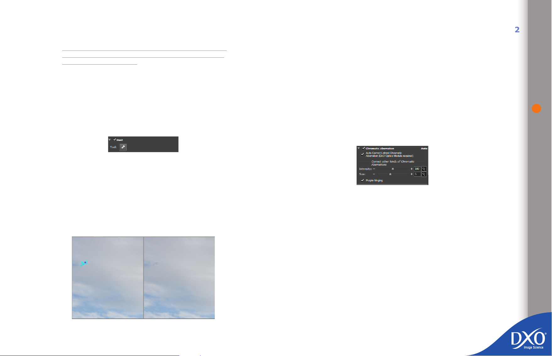
slightly de-saturating neutral tones around mid-gray, to minimize spurious color
8
7
6
5
4
3
toc12
effects in these sensitive areas.
TIP: You will probably be able to leave this correction at the
default setting unless you notice the effect it can have of de-saturating certain pastel tones.
Finally, a checkbox enables a special “Remove dead pixels” algorithm to eliminate
“dead pixels” – sensor elements that, for whatever reason, fail to record the
incident light correctly, showing up as bright spots on the image. You can leave
this box checked all the time, as this phenomenon can occur on many cameras
at a very high ISO setting, even though it is invisible at lower speed ratings.
If you click on “+ Advanced settings +”, you will see a further panel with additional settings. Click on “- Advanced settings -” to hide this panel.
Dust
This anti-dust tool allows you to “paint” a line (whose thickness can be adjusted)
or to position a dot (of variable diameter) over a dust shadow or blemish detail
you want to erase. Of course, once you erase dust and blemishes on one image,
you can make a preset from these settings and reuse it on other images.
To use the Dust tool, follow these steps:
Open the “Dust” rollup and click on the tool. Two copies of the image
•
appear side-by-side; the tool is enabled at a zoom of 75% or more.
Using the blue circle cursor, position a dot or line or draw a mask where
•
the dust or blemish is located. Don’t forget to zoom in to the image to
make masking of the dust or blemish easier. The width of the dust pen
can be adjusted with a slider that appears beneath the left-hand image.
The dust is removed on the “after” image.
If you wish to remove a correction, simply select the blue mask with the
•
Dust tool enabled. The mask will turn dark blue: remove it by pressing
the “Del” key..
To delete all masks, use the “Reset” button
•
Chromatic Aberration
42
When you rst click on the dust tool, two images will be displayed in the “IMAGE”
pane. The left-hand one is the “before” image and the right-hand one the
“after”.
Each blue dot on the original image will be corrected in the processed image.
Lateral chromatic aberration (e.g. magenta or green fringes alongside a straight
line) is only corrected if the appropriate DxO Optics Module is available.
Whether or not the appropriate DxO module is loaded, there are two manual
adjustments available for correcting chromatic aberration. To the right of them
are magic wand icons so that you can revert immediately to the automatic or
recommended value settings.
The rst “Intensity” slider / edit box, with a range from 0 to 200, adjusts
•
the correction intensity for all types of chromatic aberration: this basically
affects tiny colored transitions, which may generally be assumed to be
the result of chromatic aberration rather than actual picture content.
The second “Size” slider / edit box, with a range from 0 to 12 arbitrary
•
units, adjusts the width of the colored fringe that will be suppressed: this
basically affects the way DxO Optics Pro decides what is considered to
be chromatic aberration that needs to be corrected and what is wanted
picture content.
The Purple fringing correction just has a checkbox to enable or disable it and
is particularly useful when this defect is visible on edges in backlit images (e.g.
tree branches).
Page 43
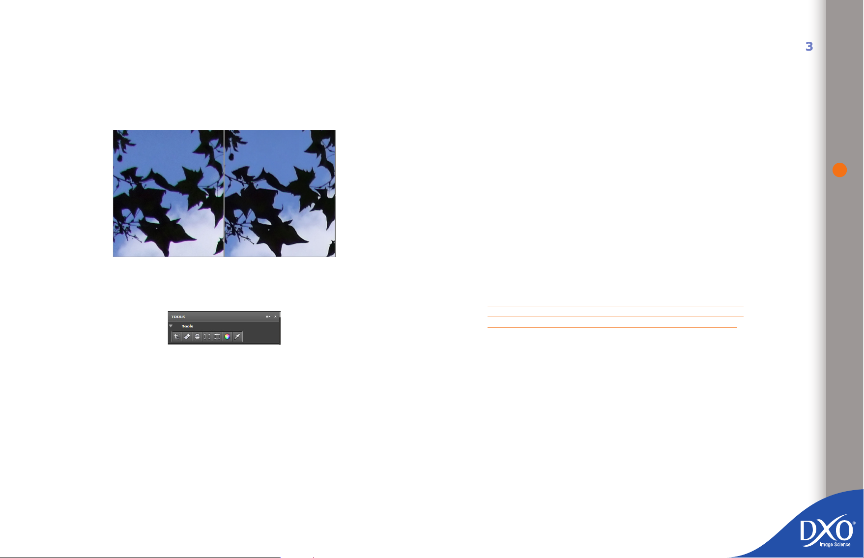
For all of these corrections, you are advised to select a 100% display or larger in
8
7
6
5
4
3
toc12
order to see the effect of the corrections in detail. However, even if you do not
change the default values, it is useful to check the “Purple fringing” checkbox
for all backlit shots taken with lenses that commonly display these defects, or
even create a preset for systematically correcting it.
Note: Overall chromatic aberration correction must be enabled for this function to
become available.
Before After
4.5.2.4 Tools Palette
4.5.3 My Palette
My Palette is the generic name for an extra palette that you can freely create or
customize in addition to or in place of the palettes available in the DxO Optics
Pro workspaces. Once you have worked with the program for a while you will
probably notice that there are some controls that you use more often than others.
Instead of opening a whole series of palettes, you can create your own custom
one. In the “Palettes” dropdown menu to the right of the “Customize” tab and
underneath the “Workspace” dialogue box, simply select “Create user palette”. A
“My Palette” palette is created by default but can easily be renamed. Remember
that to access all available commands you rst need to select the “DxO Advanced
user” workspace.
Simply drag the rollup you need from any correction palette: a duplicate of this
rollup will appear in My Palette, which you can then use in exactly the same way
as the original. The original has not disappeared, it’s just that an alias has been
installed in My Palette.
You can repeat this operation with more rollups to build the perfect set of tools
for your needs. Conversely, you can clear My Palette of rollups you don’t need
any more by dragging them away from it. From this point on, it’s perfectly possible, for work that follows a pattern you are used to, to normally use just one
correction palette... that you’ve put together to suit yourself.
NOTE: To save your custom palette(s), you need to save them in
a personal workspace (see Chapter 4.4.4) as it is not possible to
alter DxO Optics Pro workspaces by adding palettes to them.
43
4.6 Presets
The “Tools” palette consists solely of a number of icons that provide a shortcut
to several rollups included in the correction palettes. They have exactly the same
function:
the Crop icon equates to the “Crop” rollup in the “Geometry” palette
•
the Dust Removal Tool icon equates to the “Dust” rollup in the “Detail”
•
palette
the Horizon, Force parallel and Rectangle icons equate to the “Keystoning
•
/ Horizon” rollup in the “Geometry” palette
The Multi-point color balance tool equates to the “Multi-point color
•
balance” rollup in the “Color” menu
the color picker icon equates to the “White balance” rollup in the “Color”
•
palette.
4.6.1 What is a preset?
A preset describes the correction settings to be applied to images in the Project
when they are displayed in the “Customize” tab or during processing. A preset
is automatically applied to each image added to a Project.
DxO Optics Pro is supplied by default with a number of presets (described below)
but you can also create custom presets for yourself. The “preset” function is a
powerful tool that allows you to quickly apply a combination of settings (supplied
with DxO Optics Pro or ones you have created yourself) to one or more images,
without getting into the detail of the correction rollups.
By using presets, you can apply your preferred settings to achieve the kind of
result you want and then work on each image individually to ne-tune corrections
and adjustments that perhaps need to be done on an image-by-image basis.
Page 44

Some settings are only available for RAW images: presets that affect these
8
7
6
5
4
3
toc12
settings are agged “(RAW only)” to warn you that they will not produce the
expected effect on input images that have not been shot as RAW images.
Finally, a preset can include all or just some of the correction settings available
in DxO Optics Pro. This principle is illustrated below with the presets supplied
with the software.
4.6.2. Presets supplied with the software
Around 20 presets are supplied with DxO Optics Pro. These are accessible from
the dropdown menu to the right of the “Add to Project” button in the “Select”
tab, or by right-clicking on the thumbnails in the “PROJECT” pane, or via the
“presets” dropdown menu in the “Customize” tab. These are described below:
4.6.2.1 Direct-access presets:
DxO Default v2 preset – This basic preset is applied by default to all
•
images imported into DxO Optics Pro, unless you select another preset
during the photo-selection stage. It contains all the basic corrections,
as long as you have the necessary DxO Optics Modules:
LIGHT: Lighting set to Slight auto; Vignetting set to auto.
COLOUR: Color rendering unchanged for processing JPG images, and
default camera color rendering set by manufacturer for processing RAW
images.
GEOMETRY: Distortion set to auto.
DETAIL: Lens Softness activated and ‘Global’ slider set to –0.5 (i.e.
average correction) with ‘Detail’ slider set to 50; Chromatic Aberration
set to auto (with lateral chromatic aberration acti¬vated) and DxO Noise
set to auto.
All other corrections are disabled in this preset.
NOTE: In the “Select” tab, it is always the most recent preset
selected that appears when you start a session, not the DxO
Default v2 preset.
DxO Default v2 – Neutral Color (RAW only) – This preset is identi-
•
cal to ‘DxO Default v2’ except for the color rendering, which has lower
saturation and contrast in order to reproduce the scene more faithfully.
This is only relevant for RAW images, and is particularly suitable for
professional photographers.
DxO Default – Original (v1) – This preset used to be the default preset
•
up to DxO Optics Pro version 6.2. It differs from ‘DxO Default v2’ in that
the Lens Softness ‘Global’ and ‘Detail’ sliders are both set to 0.
No correction – This preset disables all DxO Optics Pro corrections. Of
•
course, when applied to a RAW image, DxO Optics Pro still takes care of
RAW conversion (with the basic settings for the camera).
Note: the “DxO default v2”, DxO Default v2 – Neutral Color (RAW only), DxO Default
– Original (v1) and “No correction” presets are the only settings in the software that
affect all the settings for a particular image.
4.6.2.2 Presets in folders
DxO Optics Pro includes three sub-directories containing specic presets:
“color and contrast adjustment”, which contains presets that only affect
•
settings for image color and light corrections
“noise adjustment”, which contains presets that only affect settings for
•
correcting image detail
“geometry adjustment”, which contains presets that only affect settings
•
for correcting image geometry
These presets therefore only affect a certain number of settings. When the
user uses these when importing images into a project, the settings that are not
affec¬ted by the presets are set to the DxO Default v2 preset value (to continue
to benet from all the automatic corrections offered by the software).
The “Color and contrast” folder includes 12 different presets:
•
Natural colors (RAW only): Produces natural colors to render the
colors in a scene as faithfully as possible. Suitable for most RAW photos
if you prefer a fairly natural color rendering.
Realistic color variation 1, 2, and 3 (RAW only): These three presets
offer three other color rendering variations to produce colors to your
taste.
Highlight recovery – slight (RAW only): Recovers the detail availa-
ble in large burnt-out areas and maintains a generally pleasing level of
contrast. Suitable for high-dynamic-range scenes with highlights that
are burnt out but contain useful detail (cloudy sky, snow elds, wedding
dress, candles, an open re, etc.)
Highlight recovery – medium (RAW only): Recovers more detail
available in large burnt-out areas and maintains a generally pleasing
44
Page 45
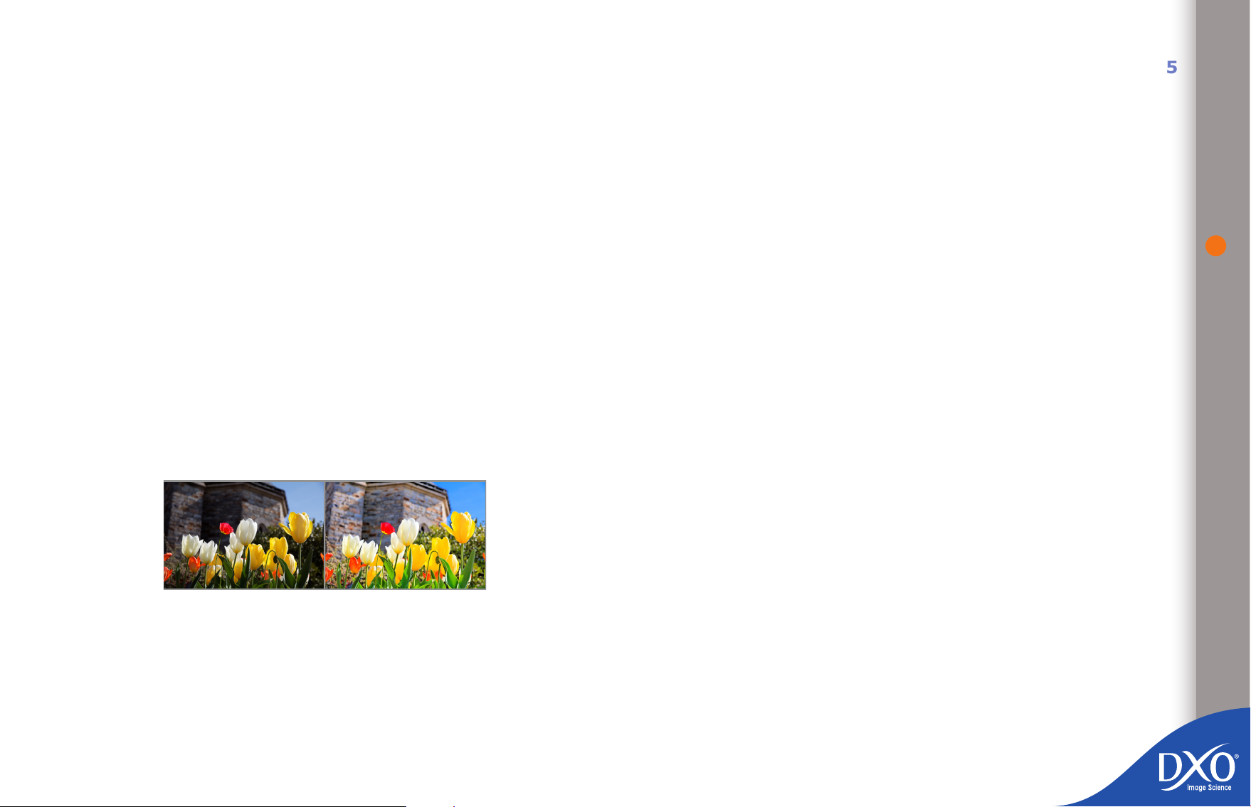
level of contrast. Suitable for high-dynamic-range scenes with highlights
8
7
6
5
4
3
toc12
that are burnt out but contain useful detail (cloudy sky, snow elds,
wedding dress, candles, an open re, etc.)
dows. Suitable for all photos taken in low light or at high speed or a
combination of the two. Night and action shots and indoor photos without
ash.
45
Highlight recovery – strong (RAW only): Recovers all the detail
available in large burnt-out areas and maintains a generally pleasing
level of contrast. Suitable for high-dynamic-range scenes with highlights
that are burnt out but contain useful detail (cloudy sky, snow elds,
wedding dress, candles, an open re, etc.)
General – Vivid colors: A “creative” preset for vivid colors and high
contrast. Suitable for landscapes, architecture, still life compositions and
nature photos if you prefer marked contrasts and saturated colors.
General – Negative colors: Reverses the colors in a photo to give it
the appearance of a negative
Landscape – Postcard: Increases color saturation and contrast. For
landscape and travel photos if you want to boost colors and contours,
as on postcards.
Landscape – Lowkey: Reduces the overall level of exposure while
increasing contrast. Very effective for urban landscapes, industrial buildings or “distorted” nature photos.
Landscape – Highkey: Drastically reduces the density of a photo whilst
preserving detail and highlights. Useful for misty landscapes, photos of
the sea in the morning, or romantic portraits.
The “Geometry adjustment” folder offers two different presets:
•
Group portrait – restore face proportions: Restores the proportions
of faces that appear distorted away from the image centre. For group
photos taken using a wide-angle lens with multiple faces right across
the image.
Group portrait – restore body proportions: Restores the proportions
of bodies that look distorted and fatter at the edges of the image. For
group photos taken using a wide-angle lens with several people standing
next to each other in a line.
4.6.3 Applying presets
There are several ways of applying a preset to an image:
when you add an image to the project (from the dropdown menu to the
•
right of the “Add to project” button in the “Select” tab)
by right-clicking on a thumbnail in the “PROJECT” pane at any time
•
from the “Presets” dropdown menu on the icon bar in the “Customize”
•
tab
from the “Preset Editor” palette
•
When you add images to the project, any settings not affected by the chosen
preset are set to the DxO default v2 preset value.
When you apply a preset to an image already in the project, a dialogue box opens
to ask you whether the selected preset should be applied:
in addition to the image’s current settings (handy if you want to preserve
•
Preset Landscape Postcard
The “Noise adjustment” folder offers two different presets:
•
Color anti-aliasing (RAW only): Eliminates areas of colored moiré.
Very appropriate for photos of clothing with regular patterns or any other
objects with a ne, regular structure. Also ideal for photos of hair, fur or
feathers.
High ISO – noise reduction: At very high ISO settings, the best compromise between noise reduction and preserving detail and dark sha-
the effects of your previous settings on the image: for example, you
may have adjusted the image’s white balance manually and now want
to apply the High ISO – noise reduction preset)
in addition to the DxO Default v2 preset (useful if you want to reset all
•
settings to their “DxO Default v2 preset” default values and then apply
the preset you have selected)
Page 46
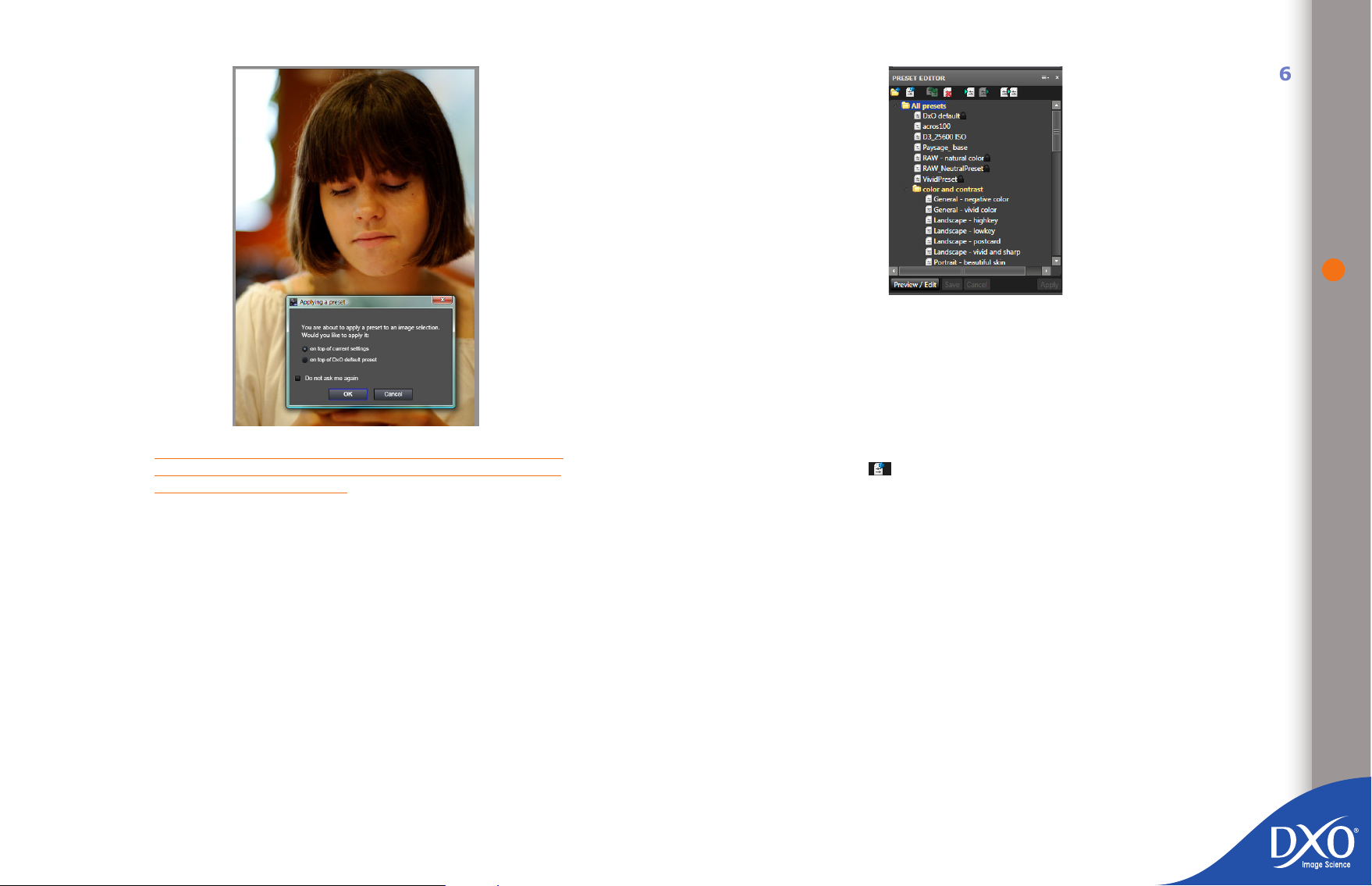
4.6.5 “Preset Editor” palette
8
7
6
5
4
3
toc12
This section describes how the “Preset Editor” works: this palette is available in
the “Advanced user” workspace.
4.6.5.1 Creating a new preset
46
TIP: The shortcut Ctrl + Z in Windows or CMD + Z on a Mac
lets you undo the immediately-preceding preset application and
revert to the previous setting.
4.6.4 Creating presets
There are several ways of creating presets:
Via the “Create preset based on current settings” function, accessible
•
by right-clicking on a thumbnail in the “PROJECT” pane or from the
“Presets” dropdown menu in the “Customize” tab: all the settings associated with the image will be saved in a preset that you can then name
and save in a directory or sub-directory of the “Presets” directory. The
preset you have created will affect all setting values.
Via the “Preset Editor” palette, cf. section 4.6.5.
•
If you are a new user, we recommend you use the rst of these options for
creating your presets.
To create your own preset, rst click on the “Preview / Edit” command and then
the “New preset” icon in the command bar at the top of the editor. Name
your preset by right-clicking on the name “New preset” in the list that appears
in the directory tree.
At the moment this preset does not contain any settings, so you need to go into
“Edit” mode.
You can also create a preset based on the settings for the current image by clicking on the icon in the upper right-hand corner of the “Preset Editor” palette. In
this case, editing the preset is optional.
4.6.5.2 Editing
This involves deciding which corrections you want to include in your preset and
the value for each setting.
Select a preset from the list in the “Preset Editor” palette and then click on the
“Preview / Edit” button. A vertical bar of orange boxes is displayed to the left of
each rollup. If you click the orange box next to a particular rollup, the settings
for that rollup will be included in your preset. Don’t forget to check whether the
rollup in question is active (the checkbox in front of the name of the palette
must be checked).
Page 47
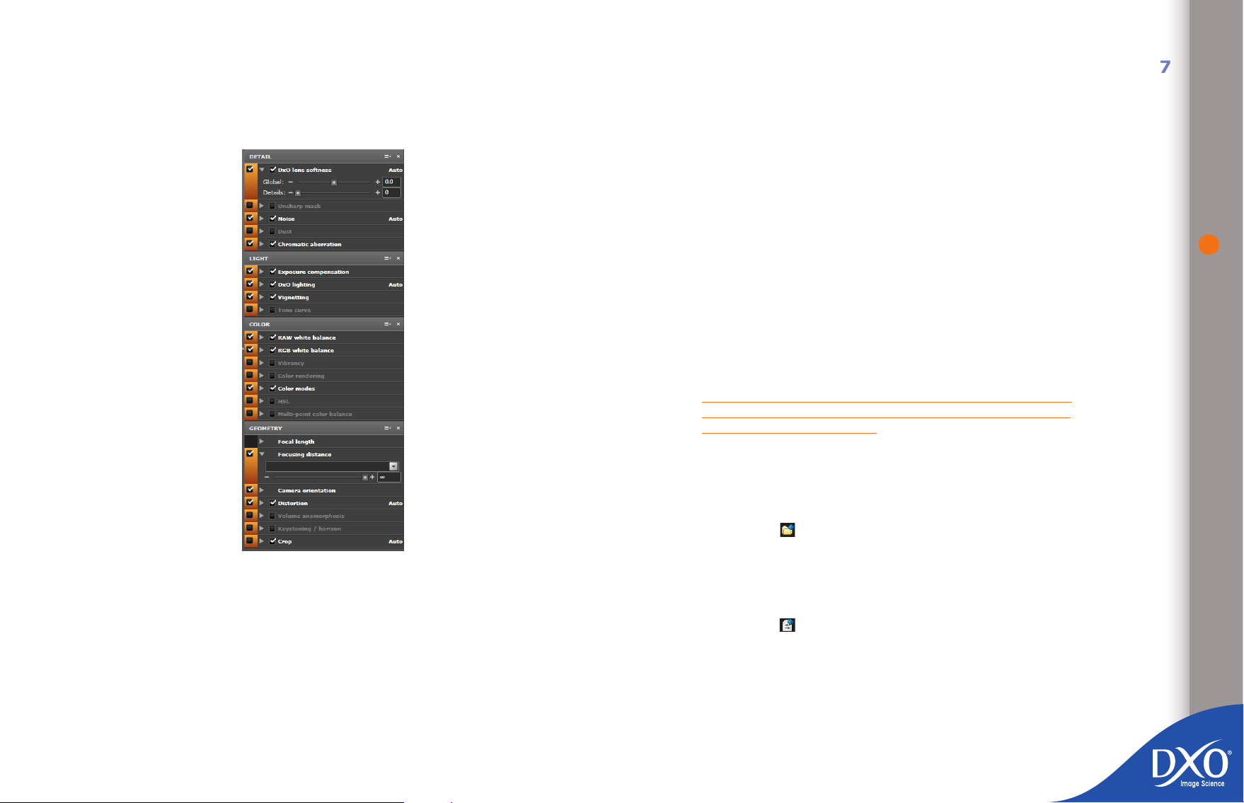
Settings for any rollups that are not checked will not be active (in the following
8
7
6
5
4
3
toc12
example, which is designed for sunny landscapes, noise reduction would not be
of any use, so you would not click the orange box for this rollup). For each setting
included in your preset, you can either retain its automatic values or assign a
predened value of your own.
You can create as many presets as you want, le them in folders and then import
them into other versions of DxO Optics Pro and export them to share with other
users of the software.
4.6.5.3 Applying a preset
When you select a preset you can see how it will change the current image by
clicking on the “Preview / Edit” button. To apply it to the current images you are
processing (a single image, a stack, or a selection), click on the “Apply” button.
Remember that you can call up a preset (but not change it) by right-clicking on
a thumbnail.
4.6.5.4 Canceling the application of a preset
If after checking you decide you have applied a preset wrongly and you want to
undo its effects, whether this preset was called up from the main dialogue box
in the “Customize” tab or by right-clicking on an image or stack, all you have
to do is open the “Edit” menu and click on “Cancel” to delete the preset from
your selection. The ‘Redo’ command has the reverse effect and will re-apply the
preset to your image.
TIP: The shortcut Ctrl + Z in Windows or CMD + Z on a Mac
lets you undo the immediately-preceding preset application and
revert to the previous setting.
4.6.5.5 Details of commands in the Preset Editor palette
47
The following icons appear in the top section of the “Preset Editor” palette. From
left to right, these are:
New Folder – allows you to create folders in which you can group
•
similar types of presets. By doing this, you can create custom groupings
Once you have nished editing, save your preset by clicking “Save” and click on
“Preview / Edit” to exit the edit mode and remove the bar of orange boxes.
Don’t forget to click on the “Apply” button to associate this preset with your
image. Otherwise, you will have edited and saved a preset but not applied it to
your image.
The commands you checked in the orange boxes will be included in the preset.
Commands that were not checked will remain unchanged when you apply your
preset.
of presets to suit the way you work, for example, by type of camera
used, high speed rating, landscape rendering, portrait, etc.
Note: You can move a preset to a different folder using drag-and-drop.
New Preset – allows you to create an “empty” preset, i.e. one that
•
does not contain any settings. You will then need to edit your new preset.
If you select a folder before you create your preset, it will be created in
this folder.
Page 48

Copy – this lets you start off from an existing preset to create a
8
7
6
5
4
3
toc12
•
variant, which you can rename and modify. You will need to use this
method if you want to create variants of a locked DxO preset.
Delete – the selected preset or folder will be deleted.
•
Import – this button lets you import presets created previously in
•
other versions of the software, or available on another computer, in order
to use them in DxO Optics Pro 6. Clicking on the Import icon will open a
directory tree that will allow you to nd the le(s) you want to import.
Export – you can export the preset to a directory for copying onto
•
another computer or sending to a friend via e-mail.
creates a new preset with the settings of the currently previewed
•
image.
In the main list, you’ll see that in front of each folder is a “+” (a triangle on the
Mac version). By clicking on the “+”, the sub-folders will expand just like a tree
directory in Windows Explorer.
If you click on the New Folder icon, a new presets folder will be created. By clicking on the new folder’s name you can rename or delete it. Depending on how
you name your new folder, it will be automatically placed above or below the
default preset folder. We would recommend that you give your folders meaningful
names so you can remember how you have your presets grouped. Your folder
can be renamed, just like any system folder, but don’t forget that if you delete it
to reorganize your presets, you will also be deleting the presets it contains: as
a precaution, it is a good idea to export all your presets to a back-up directory
on an external hard drive or USB key!
48
If you rst select a folder and click on the New Preset icon, a “+” will appear to
the left of the folder name if this is the rst le you have created in this folder.
Otherwise, a new preset with a default name will be created in the folder.
Page 49

Chapter 5
8
7
6
5
4
3
toc12
“Process” tab
The rst time you process your images with the program, it will automatically
generate copies in a high-quality JPEG format in the same directory where the
original shots were saved; if your photos were saved in a number of different
directories, you can opt to have a “DxO Optics Pro 6” folder created in each
one. Later on you will learn to create a number of output formats depending
on the use you want to make of them: images for the web, high-quality TIFF
enlargements, digital archives for later nishing with Photoshop in the Adobe
DNG format, etc.
To start processing, simply click on the “Start processing” button. A progress
bar shows how you how far the process has progressed and the icons on the
thumbnails on the photos switch in turn from “To be processed” (blue star) to
“Processed” (green tick).
The choices to be made in terms of processing involve deciding on output formats and the folders where the images will be saved. To access this command
click on the “Show output settings panel” button or the vertical separation bar
to the left of the image: the various output settings will appear to the left of the
main pane.
49
“Process” tab
Page 50
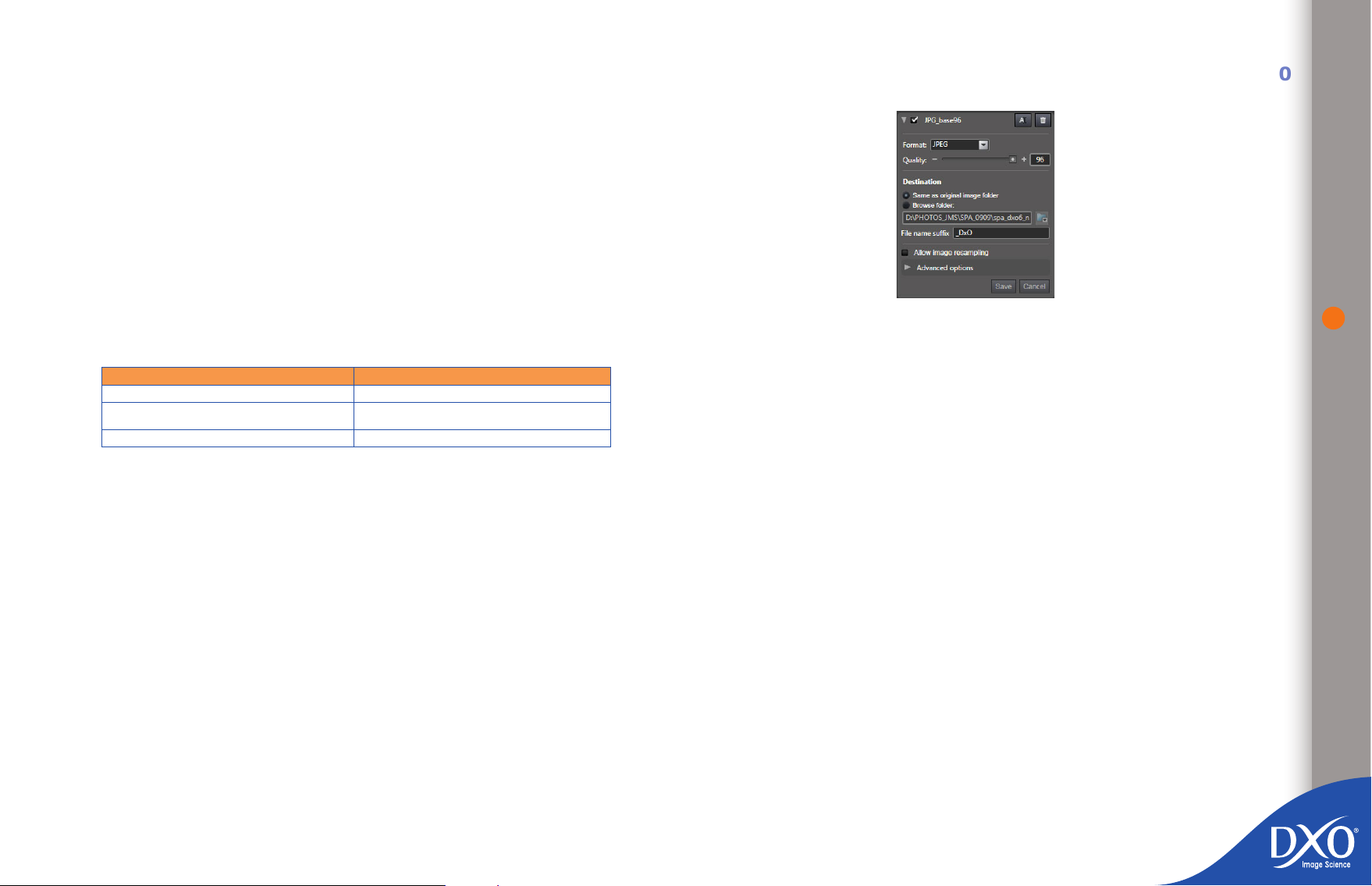
5.1 “Process” tab commands
8
7
6
5
4
3
toc12
The top part of the “Process” tab is divided into two areas as soon as you click on
the “Show output settings panel” button or on the left-hand vertical separation
bar, whilst the “PROJECT” pane remains in the bottom section of your screen
(unless you have made it oating). In the “Output settings” pane you can dene
how the corrected versions of your images are generated and into which directory
they will be copied; unlike many other batch-processing operations, DxO Optics
Pro lets you generate several copies of your images in a single pass, e.g. a DNG
or 16-bit TIFF output for subsequent highly sophisticated retouching, a JPEG
for quick prints on an ink-jet or photographic printer and another JPEG already
res¬caled for the web or an image-hosting site such as Flickr.
You can create as many output settings as you want, provided you give them
all different names (for example, JPEG HQ, JPEG medium, JPEG web, etc.) Note
that saving to DNG (Digital Negative Format, © Adobe) is only possible for RAW
les.
5.2 JPEG output formats
The JPEG format is designed for les that will be printed in photo processing labs
and photos that will be printed online or sent by e-mail.
50
Input le formats Output le formats
JPEG JPEG, TIFF (8-bit)
TIFF
RAW JPEG, TIFF (8 ou 16-bit), DNG
A copy of the corrected image will be generated for each output setting, for every
image in the batch. A summary of all the available output settings is shown, and
you can check the ones you want to enable for this processing session. You must
have at least one output format active for processing to begin.
If you change any of the output settings after you have already started processing the images in your project, DxO Optics Pro will ask you whether you want
to re-process the images that have already been completed.
To create a new output setting, click on the “Create a new output setting” icon to
the right of the heading on the “Output settings” palette. The rst time you use
the software there will only be one JPG output setting available, called “Untitled
1”. Every time you click on the icon to create a new output setting, a new dialo-
gue box will be generated: you can open this by clicking on the arrow to the left;
this must be checked for the box to be active. First of all, give your new output
setting a name. Then select the basic settings and any advanced settings you
want by expanding the “Advanced options”.
The rst thing you must do is to select an output format (JPEG, TIFF or DNG)
to show the settings available, as these vary depending on the format you
choose.
JPEG, TIFF (8 or 16-bit depending on
input)
5.2.1 Quality
Now select the degree of compression and hence the quality of the output format.
(The size of the image les depends on this option: the higher the quality, the
larger the output les). As JPEG is a destructive format, it is better to opt for high
quality (e.g. 90) and a smaller image size than applying a very high compression
rate (e.g. 30) on a maximum-size image.
5.2.2 Destination
Images are sent to their source directory by default, but you can also specify a
destination folder. You can choose to place the output les in the same folder as
the input les or browse to a specic folder you have created for your processed
images (e.g. DxO outputs).
Note that the directory le path can be absolute (for example, “C:\Photos\Output
DxO Optics Pro”) or relative (“Output DxO Optics Pro”). In the case of an absolute
path, all the corrected images will be saved in a single directory even if the source
images were split across several different directories. In the case of a relative
path, the corrected versions of the images will be found in a sub-directory of the
input directory, which helps to keep the corrected images “close” to the source
images: the same number of sub-directories will be created as there are source
directories (i.e. the directories in which the source images are saved).
If you do not specify an output directory, the corrected images will be saved in
the same directory as the source images.
Page 51
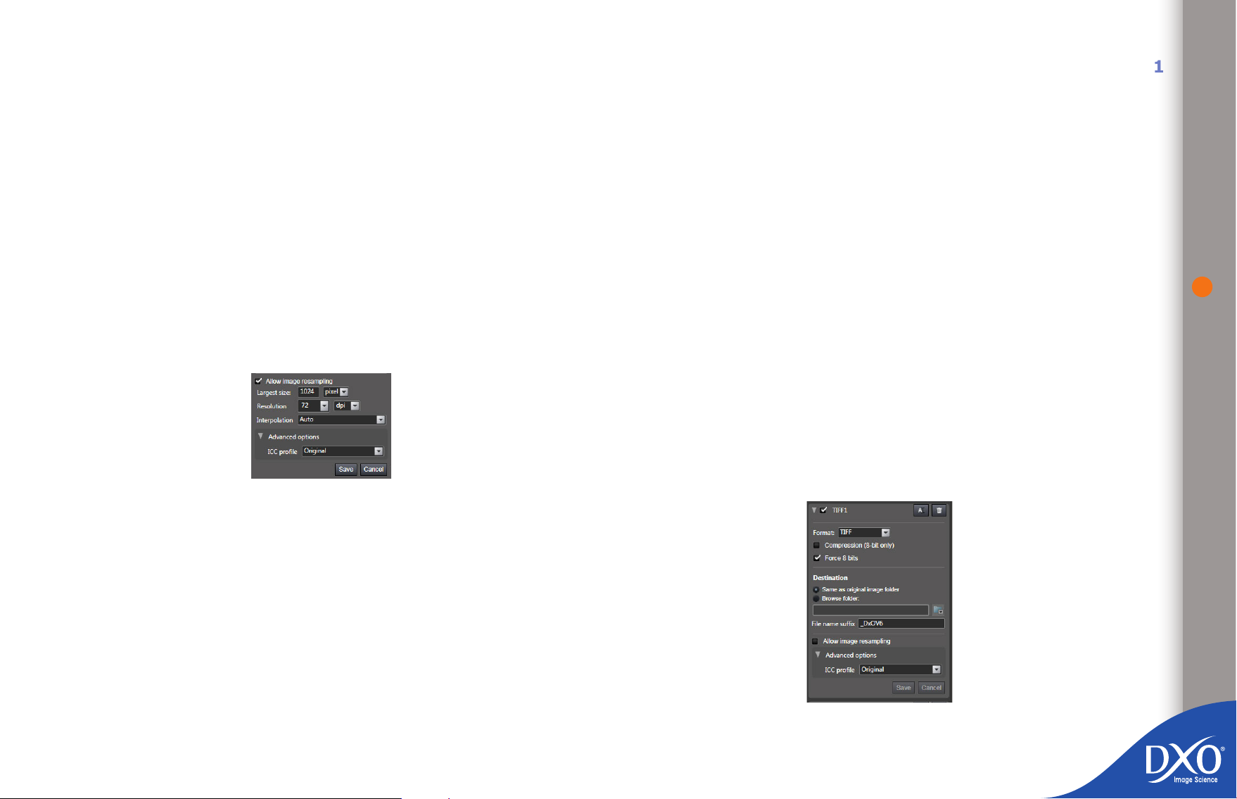
5.2.3 Sufx
8
7
6
5
4
3
toc12
5.2.7 ICC Prole
51
DxO Optics Pro adds a sufx to the original le name, by default “DxO” or any
other character string you choose. This sufx is essential in the case of JPEG les
if you are going to place the corrected images in the same folder as the originals
of the same format, to ensure you don’t delete them in error. If your images
come from a RAW le, the software will automatically add a “_raw” sufx to the
le name unless you have changed your preferences in the program.
5.2.4 Size
You can select the output image dimensions by clicking on the “Allow image
resampling” command. If you ll in the box for the largest dimension (length
or width, in pixels or centimeters), the software will recalculate each image
so that it retains the same aspect ratio as the original. For images intended
for subse¬quent retouching, the best solution is to keep the original size and
only resize once you have nished all your post-processing operations. For the
web, you can choose widths of approximately 800 to 1500 pixels and heights of
between 500 and 1000 pixels, depending on the site.
It is possible to select an output ICC color space prole (including sRGB,
AdobeRGB or a custom prole). In practice, the sRGB prole is suitable for web
uses and output on photographic or ink-jet printers. Choose the AdobeRGB prole
for images that will need to be retouched, e.g. for publication, but in this case
TIFF or DNG outputs are denitely recommended in preference to JPEG. The
custom prole is suitable if you have a printer with its own ICC prole.
5.3 TIFF output formats
The TIFF format is designed for les you intend to archive or which will be further
post-processed with almost any of the programs on the market.
5.3.1 Quality
For TIFF les you have the option of a compressed (for lighter les) or noncomFor TIFF les you have the option of a compressed (for lighter les) or
non-com¬pressed format (with the latter there is less risk of incompatibility
with older or less common programs). If you are starting out with a RAW le
or a TIFF le that has been coded to the same standard, you can select a 16-bit
option for more nuanced colors (65,536 shades possible for each color layer,
compared with 256 for 8-bit); some non-specialist software, however, is unable
to process 16-bit TIFF les and very few printers can take advantage of it as yet,
but you will be archiving the most precise possible les for the future. However,
as cameras only code JPEGs in 8-bit, you can only use 8-bit TIFF as the output
setting for source les in this format.
5.2.5 Interpolation
Several resizing options are available if you decide to change the size of the
output le: you can generally leave the command set at “Auto”, but many photographers are loyal supporters of bicubic interpolation, for optimum precision.
5.2.6. Resolution
You can select the resolution you want in dots-per-inch (dpi) if you have chosen
a custom screen or paper format. For example, 72 dpi for screen display, 254 dpi
for a photographic printer to Kodak standards or 300 dpi for certain printers or
publication. If you are not changing the original size, don’t alter the resolution
either: it only makes sense to adjust this if you have selected an image size in
centimeters or images in setting 5.2.4
Page 52
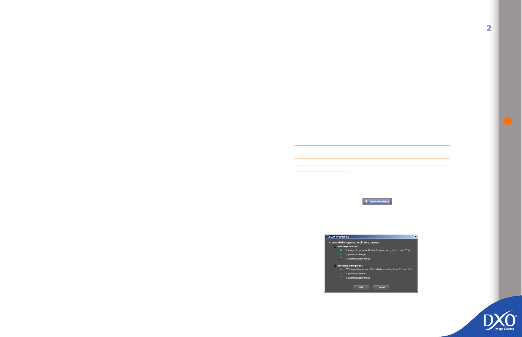
5.3.2 Destination
8
7
6
5
4
3
toc12
See “JPEG output formats/Destination”.
5.3.3 Sufx
See “JPEG output formats/Sufx”.
5.3.4 Size
See “JPEG output formats/Size”.
5.3.5 Interpolation
See “JPEG output formats/Interpolation”.
any interpolation, even if it is as excellent as in DxO Optics Pro, can cause a
deterioration in the quality of the original.
5.5 Processing
Once you have made changes to an output setting, click on “Save” to save your
setting or “Cancel” to cancel your changes. If you want to delete an output
setting, click on the “recycle bin” to the right of each button. Once you have
saved your output setting, you can click on the “Change” button in the list to
make changes to it. For an output setting to be active in the current processing
session, it must be checked.
Several output settings can be checked at the same time: this is one of the
main advantages of DxO Optics Pro compared with many other programs, which
require you to process one batch of images as JPEG les, another as TIFF les
and even more variants if there are several different output sizes.
52
5.3.6. Resolution
See “JPEG output formats/Resolution”.
5.3.7 ICC Prole
See “JPEG output formats/ICC Prole”.
5.4 DNG output formats
The DNG format is designed for les you intend to archive or which will go
through a further stage of post-processing with DNG-compatible software such
as © Adobe Camera RAW.
The DNG generated by DxO Optics Pro is a 16-bit linear DNG format. This format
is only available for original images in RAW format. No quality option is offered.
Linear DNG means that the three color channels have been interpolated and
therefore that the le “weighs” three times more than the original RAW le.
Interpolation was necessary to perform a number of optical corrections. This
format offers the same level of color and exposure control as with a RAW le
generated by the camera.
For the other options you can treat DNG les in the same way as TIFF les, except
for image size, as a le intended for archiving and/or further post-processing
should not be resized in order to maintain its maximum potential in the future;
TIP: Creating several output formats can be used to automa-
tically back up every image on several hard disks or servers.
All you have to do is dene several output formats that are
identical, except for the save directory for the nal images, for
example a removable disk or a server that is separate from the
machine you work on.
Note: At least one output format must be enabled for processing to be able to
start. If you try to start processing with no output format enabled, you’ll get an
error message.
Start processing by clicking on the icon. A dialogue box will open
to check whether you want to process the whole of the project or just the images
whose settings have been adjusted. You can also start processing by dragging
and dropping the images you want to process into the “PROCESSING” pane.
If images that have already been corrected by DxO Optics Pro (e.g. in an earlier
project) are in the same directory with the same name, the program will ask you
Page 53

if you want to overwrite the previous versions. If you answer no, the image will
8
7
6
5
4
3
toc12
not be processed. If you want to process images with the same name without
overwriting, you will need to choose a different output directory.
You can see processing is in progress by checking that the two cogs are turning
over the thumbnails of the images you are processing.
Once processing is completed, the ‘blue star’ icon turns into a green tick, indicating that processing has been successful for that image. If an error has occurred,
you will see a “!” on the image.
If you have the impression that DxO Optics Pro is not using all your system
resources, you can adjust the number of images the program processes at once
under “Preferences” (chapter 7.9.2)
53
Page 54
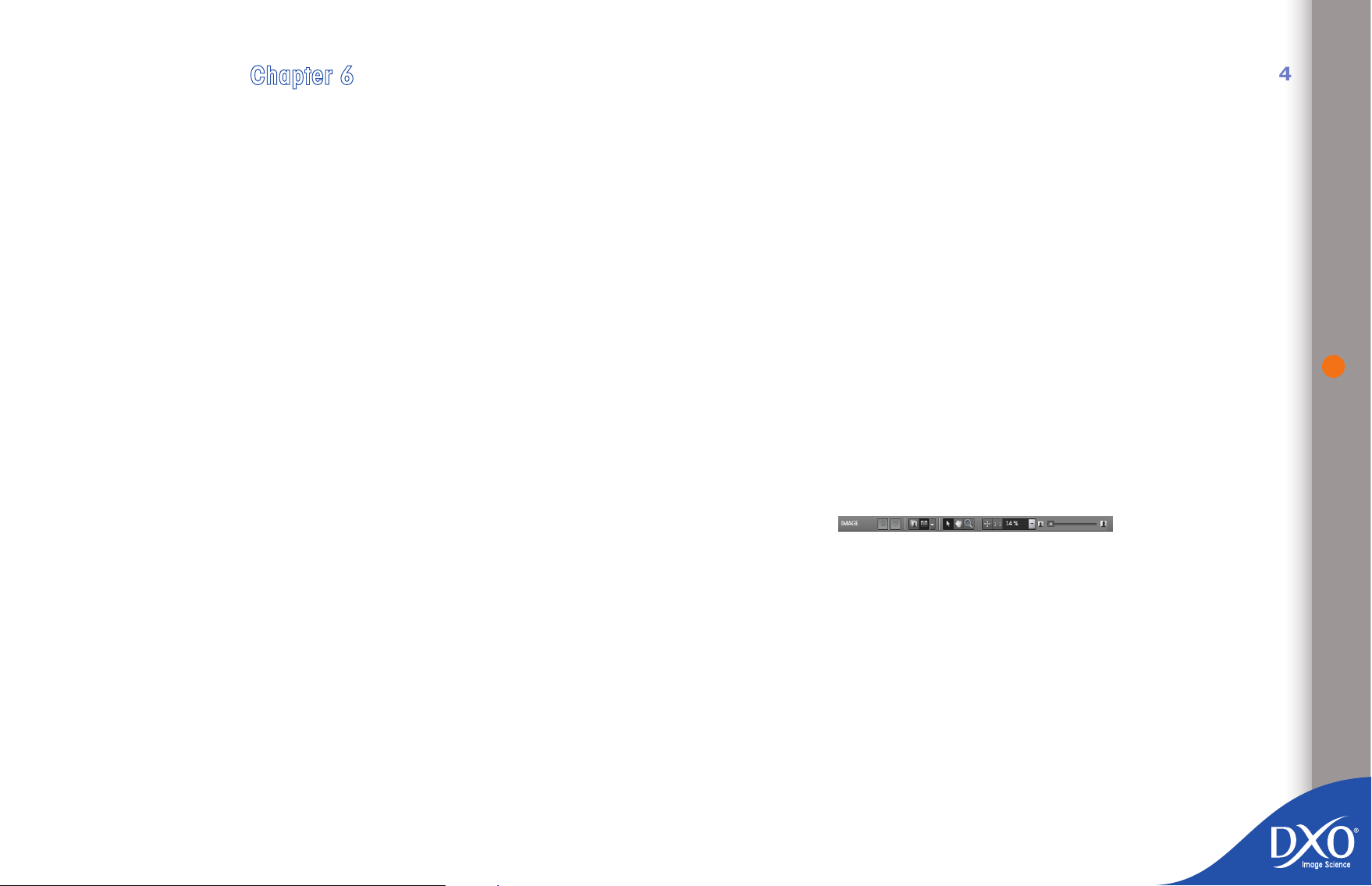
Chapter 6
8
7
6
5
4
3
toc12
“View” tab
Once processing is complete you can open the “View” tab to assess the quality
of the corrected image by viewing the nished copy rather than just the simulated version you saw in the “Customize” tab. This verication step may be very
quick or alternatively very detailed... or you can miss it out altogether if you are
condent of your abilities and your software settings. The advantage of working
through this step is that if you need to make an adjustment you can simply return
to the “Customize” tab to make changes just to the images that need it. Next
time you start a processing session a window will open and ask you if you want to
overwrite the previous corrected copies. If you click on “No”, DxO Optics Pro will
not re-process images that have already been processed. If, however, you want
to re-process them without overwriting the images you have already processed,
you will need to create virtual copies for these images (cf. chapter 4.3).
In the “PROJECT” pane at the bottom of the screen, you can select images to be
viewed (they must have been processed). You can scroll through them using your
mouse or the keyboard arrow keys; they can also be shown in “before and after”
mode, as in the “Customize” tab. You are now no longer looking at a simulation,
but the copy generated by the processing. If several outputs have been generated
for a single image (i.e. there are several active output settings), you can nd
JPEG, TIFF and DNG images in turn by using the “up” and “down” arrows to the
right of the name of the image in the icon bar in the “IMAGES” pane.
The other buttons on this bar can be used to view the original and corrected ver-
sions one behind the other or side-by-side, select a magnication factor, enlarge
a portion of the image (using the “magnifying glass” icon) or navigate around
the image (using the “hand” icon).
54
6.1 “View” tab commands
“Single image display”: the processed (corrected) image is displayed
•
in the pane. This is the nal image that has been saved to your hard
disk.
“Dual image display”: displays the reference image – by default, the
•
uncorrected image – and the nal image processed by DxO Optics Pro.
You can zoom in if necessary to compare the detail in the same area of
each image.
“Before correction” drop down menu: lets you specify which image
•
to use as a reference when comparing the corrections of the current
image. By default you compare it to the “Before correction” image, but
you can replace it by any virtual copy of the same image, provided that
the virtual copy has already been processed. DxO Optics Pro’s virtual
Page 55

copy function lets you compare virtual copies with each other quickly
8
7
6
5
4
3
toc12
and simply.
Pointer tool – when this tool is active, clicking on the corrected image
•
will display the reference image (see above) so that you can compare
it with the corrected version. Release the mouse button to return to
the nal image corrected by DxO Optics Pro. The keyboard shortcut
“Ctrl + D” can also be used to toggle between the “before” and “after”
images.
Hand tool – The hand tool can be used to move the visible area of the
•
image.
Zoom tool – Click on this icon to zoom into the image in full-frame view
•
(using the thumbwheel on your mouse if it has one) up to a magnication
factor of 1600%.
Zoom slider to adjust the size of the image displayed up to a magni-
•
cation of 1600%. Two quick commands can be used to adjust the image
to the size of the pane and zoom to 100%, which is ideal for checking
sharpness and noise.
TIP: If your mouse has a thumbwheel for scrolling you can use
it to vary the magnication level.
6.2 Next steps
you want of a single image. You can create a virtual copy by right-clic-
king on the thumbnail of the image concerned in the “PROJECT” pane.
6.2.2 Export images to Lightroom or Flickr:
Select the images to export in the “PROJECT” pane. Click on the
•
Lightroom (Lr) or Flickr icons in the icon bar of this pane and follow the
instructions.
6.2.3 Open the processed images with another application:
In the “PROJECT” pane, select the images you want to export, then click
•
on “Open with” in the “View” menu and select the application you want
to use. You can add applications by selecting them with the “Browse”
button and choosing a program name to run from your list of photo
editing applications or from a shortcut on your desktop.
6.2.4 Process images that have not yet been processed:
If you have images that have not yet been processed, for example if
•
you wanted to check the results of applying a preset before deciding to
apply it to a whole batch, simply go back to the “Process” tab and click
on “Start processing”, which will launch processing for all unprocessed
images.
55
Once you have viewed the results of your images, you can perform a number of
actions without quitting DxO Optics Pro, such as opening one or more images
in another application, exporting them to your a Photoshop Lightroom catalog
or an external Flickr gallery or nally, altering one or more settings to adjust
the corrections. To the right of the icon bar in the “PROJECT” pane there is a
command called “What next?” which opens up a help screen that describes the
various possible options.
6.2.1 Modify corrections on certain images:
Make further corrections to images by clicking at the top of the window
•
in the “Customize” tab. When reprocessing these images later on, the
new output images will overwrite the previous corrected versions. A
dialogue box in the “Process” tab will then ask you if you are sure you
want to overwrite the previous copies
To avoid overwriting previous corrected image, virtual copies will let you
•
generate as many outputs as the number of different corrected versions
6.2.5 Start a new project:
Go back to the “Select” tab. Click on “New Project” in the “File” menu.
•
The current project will be automatically saved in the DxO Optics Pro
database, and a new project will be created.
6.2.6 Quit DxO Optics Pro:
Click on “Exit” in the “File” menu to quit DxO Optics Pro. The current
•
project will be automatically saved in the DxO Optics Pro database.
Page 56
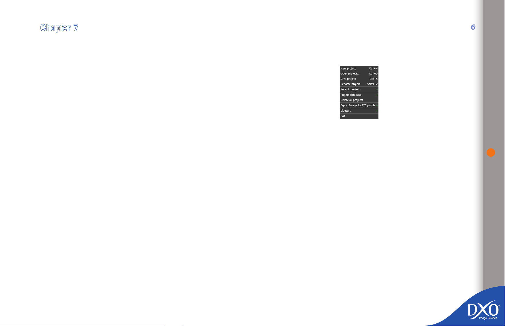
Chapter 7
8
7
6
5
4
3
toc12
DxO Optics Pro menus and preferences
When you open DxO Optics Pro, the top-most set of menus available to you is
the menu bar. This contains the dropdown menus File, Edit, Project, View, Image,
DxO Optics Modules, Workspace and Help.
7.1 File menu
The File menu includes the following commands:
New project – create a new DxO Optics Pro project
•
Open project…– open a project from the database of DxO Optics Pro
•
projects
Save project – saves the project to the DxO Optics project database
•
Recent projects – direct access to recently created projects
•
Project Database – allows you to create a backup, restore a backup
•
and import a v5 project database. The save function lets you copy the
project database to another disk.
56
Delete all projects – will remove all previous projects from the DxO
•
Project database• Export image for ICC prole – saves images which
can be used by professional calibration programs to create ICC proles
(linear RAW or realistic color rendering options available).
Sidecars – exports and imports the current project “sidecar” (the indi-
•
vidual settings le for each image) in .dxo format. Sidecars allow you to
switch original images and their settings from one computer to another
and share them with other users.
Exit – to leave DxO Optics Pro. The current project is saved automati-
•
cally when you exit the program.
Page 57

7.2 Edit menu
8
7
6
5
4
3
toc12
7.3 Project menu
57
The Edit Menu contains several useful pairs of commands to assist you in your
work.
Undo [Ctrl + Z] and Redo [Ctrl + Y] apply to the last action you
•
performed.
Cut [Ctrl + X] – lets you cut out selected text or objects from their
•
current location and places them on the Windows clipboard.
Copy [Ctrl + C] – lets you copy selected text or objects from their cur-
•
rent location and places them on the Windows clipboard. The original
text or objects remain at their current location (e.g. EXIF data).
Paste [Ctrl + V] – lets you copy the content of the Windows clipboard
•
to the current cursor position (for example, personal details to be added
into the image EXIF eld).
Select all (Ctrl + A) – lets you select all the images in a folder in the
•
“Select” tab to add them to the Project.
Refresh (F5) updates the contents of all visible folders.
•
Preferences (Ctrl >+ Shift + P) lets you make adjustments to certain
•
overall program working parameters. Full details for all the Preferences
options are listed later in this chapter.
TIP: When you rst open DxO Optics Pro the program is con-
gured by default with the simplest command options so that
you can process your images straightaway without getting
bogged down in too many complex settings. However, you can
access a range of customization options from the Edit menu >
Preferences to ne-tune the program to suit your needs.
The Project menu helps you to manage your project as effectively as possible;
with some commands are also accessible by clicking on an icon.
Project properties – displays the various characteristics (number of
•
images, date, star ranking) of the current open project.
Start Processing – starts processing the project immediately.
•
Create virtual copy – lets you create one or more virtual copies in the
•
project.
Remove from project has the same effect as the “recycle bin” icon
•
that can be displayed on the thumbnail. Removing an image from the
project has no effect on the original le.
Sort – lets you sort the images in the project in the order you want (le
•
name is the basic default criterion): other options include RAW format
images, processed images, name, size, date, dimensions, etc.
Filter – customizes how images are displayed in the “PROJECT” pane if,
•
for example, you only want to process RAW or RGB images
Stack – controls how images are stacked if this option has been checked
•
under your general preferences. Options include stacking images after
they have been selected, choosing the stack master whose settings will
be added to the rest of the stack and adding and removing items from
the stack.
Full details for the custom commands for your set-up can be found later on in
this chapter.
Page 58
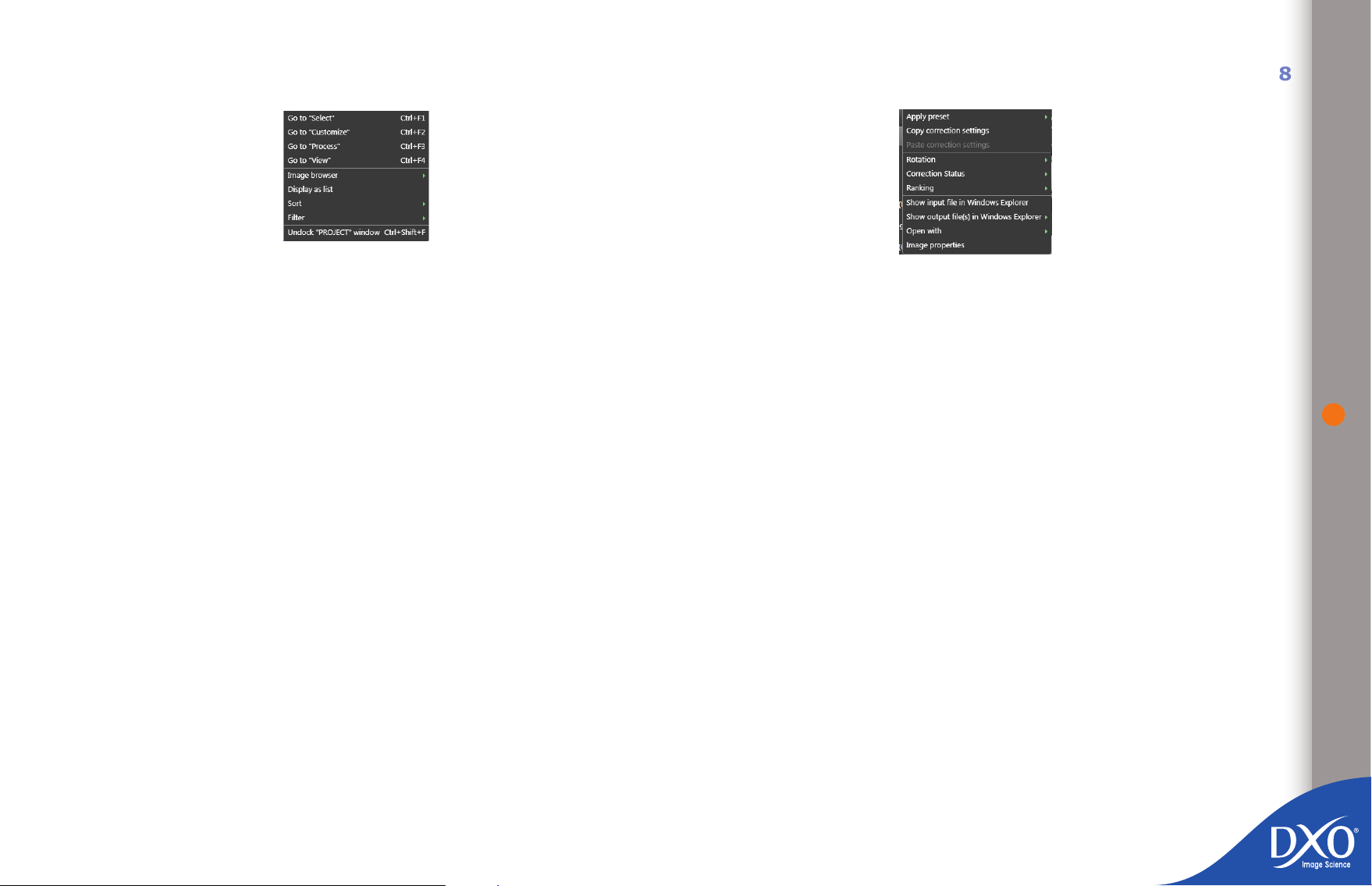
7.4 View menu
8
7
6
5
4
3
toc12
7.5 Image menu
58
The View menu lets you navigate between tabs and controls how images are
displayed in the “Select” tab.
The top-most dialogue box lets you choose between the four tabs: Select (Ctrl +
F1), Customize (Ctrl + F2), Process (Ctrl + F3) and View (Ctrl + F4).
The lower dialogue box controls the “Select” tab and is disabled if you are working in another tab:
Image browser – lets you choose whether images are selected from
•
the computer’s le system, the DxO project database or the Lightroom
database if this program is installed on your computer.
Display as list or as thumbnails functions in the same way as the
•
corresponding icon.
Sort – lets you select criteria for categorizing images in the “Select”
•
tab.
Filter – lets you choose the type of images to show in the “Select”
•
tab.
• Unlock PROJECT window or Dock PROJECT window determines
•
whether the “PROJECT” pane is docked at the bottom of the screen or
oating.
The Image menu lets you apply various commands to a selected photo and gives
you access to the following options:
Apply preset – select a preset from the dropdown menu (this can either
•
be applied in addition to current settings or in addition to the DxO Default
v2 preset: see chapter 4.6.3)
Create preset – creates a preset based on the current settings for the
•
selected image
Copy correction settings for the current image to apply them to ano-
•
ther image or stack
Paste correction settings once you have selected a new image
•
Rotation – to rotate the image if it is not automatically displayed the
•
right way up
Flag – to use the system of red, yellow and green lights that can be
•
shown on a thumbnail (a red light prevents the image from being pro-
cessed). Only visible if the “Red/yellow/green lights” option has been
activated in preferences
Ranking – allows you to rank images by quality using a star-rating
•
system. Only visible if the “Ranking stars” option has been activated in
preferences
Show input le in Windows Explorer – lets you view the location of
•
the le where the active image is saved
Show output le(s) in Windows Explorer – enables the same func-
•
tion once processing has been completed
Open with – allow you to open an image in another post-processing
•
tool, for example to print it for checking. The rst time you use the
Page 59

program you will see a “Browse” command and can then choose the
8
7
6
5
4
3
toc12
shortcut for the post-processing program you want to use.
Image properties – shows the EXIF data for the current image
•
7.6 DxO Optics Modules menu
You can use this menu to manage the DxO Optics Modules required for fully
automated processing of your images:
Install new DxO Optics Modules – connects you to the Internet to
•
choose a new module. This will be operational as soon as it has nished
loading.
DxO Optics Modules – displays the list of modules already installed
•
and lets you uninstall them (provided the Optics Module concerned is
not currently being used by the images in the project).
DxO Optics Module ambiguity – if the EXIF data for the image don’t
•
enable DxO Optics Pro determine which module to use for lenses that
have the same characteristics (but are not the same brand, for example),
a dialogue box opens so you can choose which module to use either just
for the current image or more generally.
Modules RoadMap – connects you to the DxO Labs website so you can
•
see which modules are due to be released soon
7.7 Help menu
The Help menu offers a number of aids to help you use DxO Optics Pro more
effectively. The options are:
First steps wizard – shows an introductory screen for each tab
•
Welcome screen – displays the program’s welcome screen
•
Check for update… – [active Internet connection required] When you
•
click on this menu item, the program will connect to the DxO Labs ser-
ver to determine if you have the most current version of the program
installed on your system. If this is not the case, you can download and
install the latest update.
Software license – (administrator authorization required with some
•
operating systems) allows you to activate the software and activate the
optional DxO FilmPack module. An active Internet connection is recom-
mended at this point, so that you can enter your activation code when
the system asks for it. Note: Though activation can be done without an
Internet connection, it is highly recommended that you have your com-
puter connected to an active Internet connection to simplify and speed
up program activation.
59
Suggest a Module to DxO Labs – connects you to the DxO Labs
•
website so you can suggest a DxO Optics Module you would like to be
produced.
Online help – [active Internet connection required] Clicking on this
•
menu option launches your default web browser and connects you to
the online help page on the DxO Labs web site, where you will nd links
to customer services, technical assistance, downloads and frequently
asked questions (FAQ).
Shortcuts – displays a list of keyboard shortcuts (see appendix)
•
Visit web site – [active Internet connection required] Clicking on this
•
menu option launches your default web browser and connects you to
the home page of the DxO Labs web site.
About DxO Optics Pro… – Select this menu option to view the About
•
DxO Optics Pro window where you will nd information about the version
Page 60
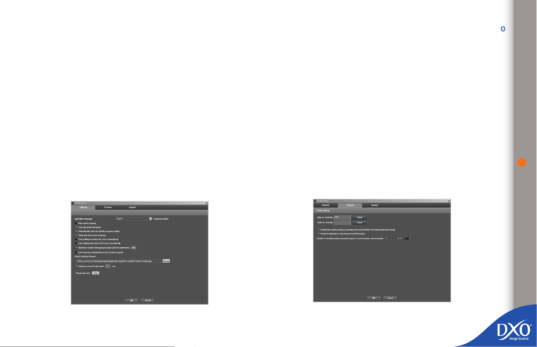
you are using and any add-ons currently installed. This information is
8
7
6
5
4
3
toc12
especially useful if you need to contact DxO Labs technical support.
7.8 Right-clicking on thumbnails in the
“PROJECT” pane
Right-clicking on an image or stack in the “PROJECT” pane brings up a context
menu that gives you quick access to a range of menu functions, such as applying
a preset immediately, copying correction settings to use them on another image,
starting processing or managing a stack of images. The commands are the same
as those in the dropdown menu.
7.9 “Preferences”: Customizing the DxO Optics
Pro interface
The “Preferences” sub-menu in the Edit menu gives you access to a whole range
of options you can use to customize some of the program’s functions to give you
an optimal environment for working on your images.
The Preferences window is divided into three tabs: General, Process and
Display.
select the application language (English, French, German or
•
Japanese);
enable or disable the “Play sound at startup” command;
•
show or hide the welcome screen;
•
save image settings in a “sidecar” le automatically: automatically saves
•
a sidecar le for every image in the project.
load image settings from a “sidecar” le automatically: loads the “side-
•
car” le and associates it with the image when it is added to a project.
limit the number of images per project (500 by default);
•
choose a location for the project database
•
About sidecars: the project database automatically contains all the settings for the ima-
ges in saved projects. These settings can be exported in the form of “sidecars” that can
then be shared with other users so that the exact settings for the image in question can
be reused on another computer. Automatically saving a sidecar therefore allows you to
create a le “image 1.dxo” for the corresponding image (“image1.JPG”) that contains all
the settings for this image. The image and its corresponding .dxo le can then be copied
onto another computer. If the “Load settings from sidecar le automatically” option has
been enabled in the version of DxO Optics Pro installed on that computer, the sidecar
will be automatically associated with this image when it is added to a project.
60
7.9.1 General
In this tab you can:
7.9.2 Process
In certain cases, it is possible to have two Source images with the same lename
but different extensions (e.g. Img34.jpg and Img34.CR2) This will be the case if
Page 61
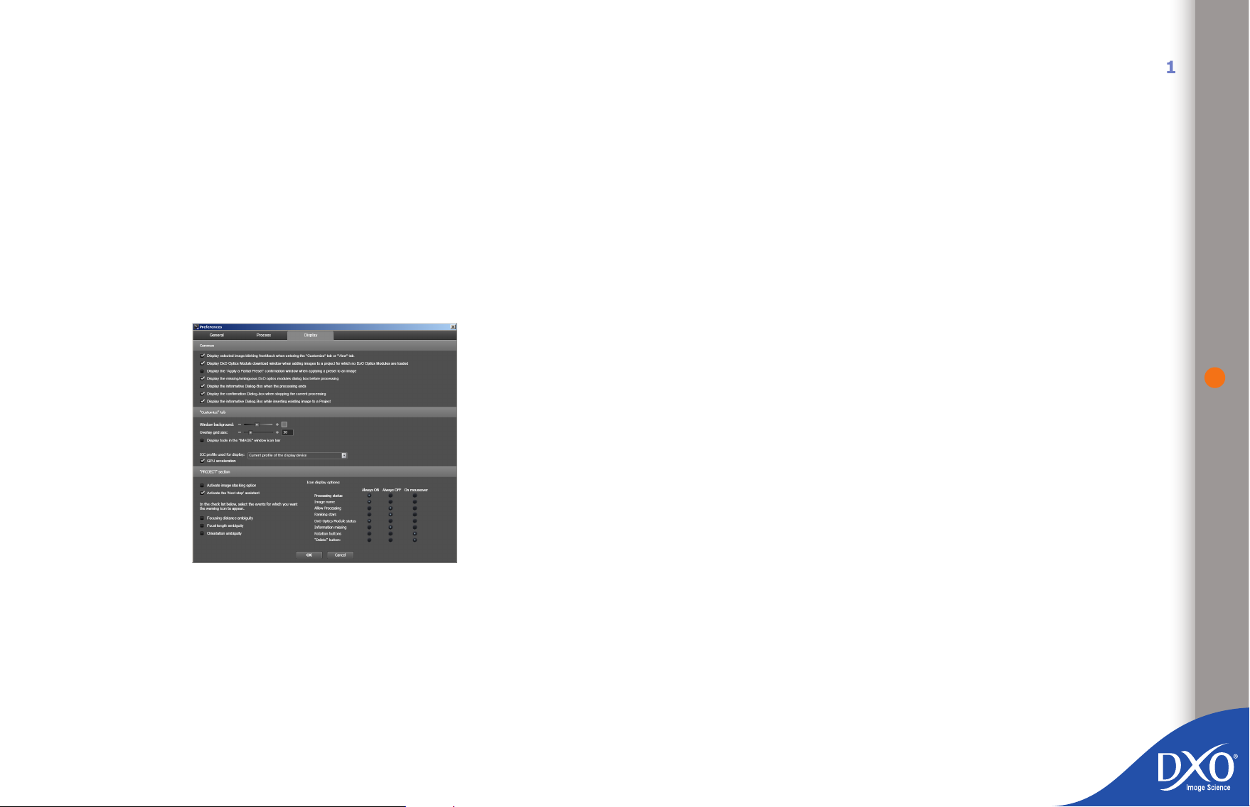
you have shot in RAW+JPEG, which you can do with most cameras. During pro-
8
7
6
5
4
3
toc12
cessing, the application will generate output images with the same name which
will overwrite each other. To avoid this, you should either add a lename sufx
for the RAW images (e.g. “_raw”, or a sufx for the JPEG images. This sufx will
only be appended in the event of the conict described above. This can be set
in the “Edit / Preferences / processing” menu.
Tab browsing during processing can be checked or unchecked (it is recommended
you leave this unchecked, as it can slow down processing).
Number of images processed simultaneously: the more memory you have available, the more images you can process at the same time. Whatever number of
processors you have, DxO Optics Pro uses all those available. It is recommended
that you do not change the default setting.
7.9.3 Display
the “Display DxO Optics Module download window” lets you see the DxO
•
Optics Module download window as soon as you add an image to the
project for which a module exists but has not yet been installed on your
computer
display the presets dialogue box: when you apply a preset to an image
•
(see above chapter 4.6.3) you can choose to add the preset in addition to
the settings already associated with the image or in addition to the DxO
Default v2 preset. The dialogue box that appears at this point allows you
to make this choice and it is recommended that you leave it showing.
7.9.3.2 Settings Customization tab
There are ve custom settings you can use:
the color of the background in the “IMAGES” pane in the “Customize”
•
and “Views” tab can be adjusted to a lighter or darker gray (the scale
runs from black to white);
the size of the grid overlay positioned over the image to check for dis-
•
tortion or keystoning can be ne-tuned to suit your needs;
the display can be accelerated by the GPU (this control should be disa-
•
bled if it causes the display to jump);
tools in the “Tools” palette can be shown permanently in the “IMAGES”
•
pane icon bar in the “Customize” tab (this means you can close the
“Tools” palette in the workspaces).
Note: Under Windows, the “Display” tab also includes another useful function, which
allows you to dene the ICC prole used when you display your images in DxO Optics Pro
(this function cannot be used on a Mac because it is the operating system that manages
the on-screen display prole). The options are:
61
Screen prole – lets you use the specic ICC prole for your monitor if
•
The Display preferences are more wide-ranging: some are very important to
ensure that your image processing sessions run smoothly.
7.9.3.1 Common
Three lines let you enable or disable some very important settings:
the rst determines whether the image is displayed blinking front/back in
•
the “IMAGE” pane when you move from the “Select” to the “Customize”
tab. Unchecking the box removes the blinking;
you have calibrated it (e.g. with a Spyder colorimeter)
sRGB – lets you use the sRGB color prole (use this if in doubt). If your
•
screen has not been calibrated, this is probably the best prole to use
as most monitors leave the factory congured close to sRGB.
Adobe RGB – lets you use this Adobe color prole. You only use this pro-
•
le with a top-of-the-range monitor with a specic Adobe RGB gamut.
Page 62

7.9.3.3 “PROJECT” pane
8
6
5
4
3
toc12
7
The display options here are extremely comprehensive and may at rst seem
rather complex, so it’s helpful to break it down into the various sections that
can be customized:
Two sections affect the overall processing interface:
you can enable or disable the image stacking option, which allows you
•
to apply the same processing to a batch of images. The photo on the
top of the stack (when the stack is collapsed) is the one on which you
adjust your settings;
you can also enable or disable the “Next step” assistant, which lets you
•
move to the next step by simply clicking on the command to the top
right of the top-most bar in the “PROJECT” pane.
The warning messages that can be displayed when you open an image are disabled by default:
focusing distance ambiguity (this information may not be included in the
•
EXIF data, depending on your camera model) can be resolved by entering it manually in the “Focusing distance” rollup (“Geometry” palette)
(more info in chapter 3.2.2.2);
focal length ambiguity involves opening a rollup in the “Geometry”
•
palette; the application alerts you to the option of ne-tuning the focal
length shown in the EXIF data (more info in chapter 3.2.2.2);
You can display up to eight types of icon on the thumbnails in the PROJECT pane
and these can be “Always ON”, “Always OFF” or appear “On mouseover”.
red/yellow/green lights to show which images are to be processed or not
•
(see chapter 3.2.2 for a more detailed explanation of these icons).
NOTE: the ‘trafc lights’ are used to show you which images
are to be processed (green light), must not be processed (red
light) or where no decision has been made (yellow light: this is
the default value). When processing begins, images with green
and yellow lights will be processed, whereas images with red
lights will not.
At the bottom of the thumbnail:
the le name, showing whether the image is a RAW or JPEG le
•
buttons for rotating the photo to the left or right.
•
62
At the top of the thumbnail:
the “recycle bin” icon can be used to remove the current image from the
•
project; this never deletes the image from the source directory;
a colored icon tells you the image’s processing status: processed or not
•
(see chapter 3.2.2 for what each of these icons means).
an icon that indicates whether a DxO Optics Module is available or not
•
(see chapter 3.2.2 for what each of these icons means).
To the left and right of the thumbnail:
stars to rate your images so that you can rank them by quality (see
•
chapter 3.2.2 for a more detailed explanation of these icons).
Page 63
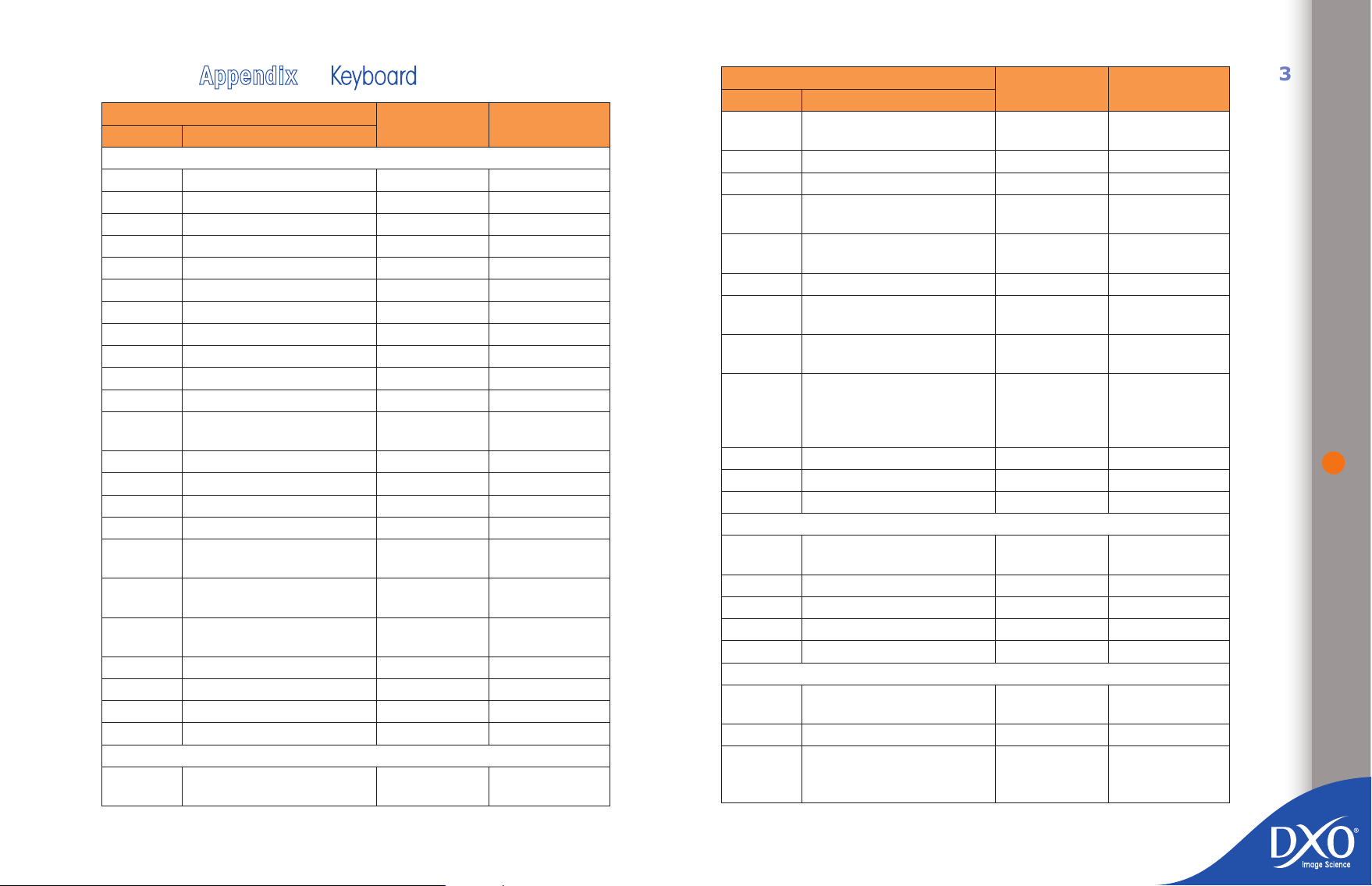
Appendix Keyboard
8
6
5
4
3
toc12
7
Function
Scope Action
General
New project Cmd-N CTRL + N
Open project Cmd-O CTRL + O
Rename project - SHIFT + F2
Save project Cmd-S CTRL + S
Quit cmd-Q ALT+F4
Copy (text elds) Cmd-C CTRL + C
Cut (text elds) Cmd-X CTRL + X
Paste (text elds) Cmd-V CTRL + V
Select all Cmd-A CTRL + A
Undo Cmd-Z CTRL + Z
Redo Cmd-Shift-Z CTRL + Y
Dock/Undock the ‘PROJECT’
pane
Go to « Select » tab Cmd-1 CTRL + F1
Go to « Customize » tab Cmd-2 CTRL + F2
Go to « Process » tab Cmd-2 CTRL + F3
Go to « View » tab Cmd-3 CTRL + F4
Display preferences window Cmd-, CTRL + SHIFT
Full screen mode - CTRL + ALT + F –
Hide/Unhide the ‘PROJECT’
pane
Next tab Ctrl-Tab -
Previous tab Ctrl-Shift-Tab -
Close window Ctrl-W -
Help Ctrl-? -
« PROJECT » pane
Copy correction settings Cmd-Shift-C CTRL + SHIFT
shortcuts
Shortcuts
Mac
Cmd-U CTRL + SHIFT +
Shift-Tab CTRL + F9
Shortcuts
Windows
F – CTRL + U
+ P
ALT + ENT
+ C
Function
Scope Action
Paste correction settings Cmd-Shift-V CTRL + SHIFT
Go to previous image
Go to next image
Rotate image selection by
90° left
Rotate image selection by
90° right
Create Virtual Copy Cmd-D CTRL + I
Ranking 0, 1, 2, 3, 4, 5 CTRL + (0, 1, 2,
Add to stack (or create
stack)
Start processing Cmd-K (pro-
Image properties - CTRL + J
Project properties - CTRL + E
Remove image from project Cmd-Del Del
« Select » tab
Hide / Unhide "BROWSE"
pane
Display le system Cmd-Shift-7 SHIFT + F9
Display Project database Cmd-Shift-8 SHIFT + F10
Display Lightroom catalogs Cmd-Shift-9 SHIFT + F11
List mode/Thumbnail Toggle Cmd-J CTRL + M
« Customize » tab
Display the reference image
(hold key)
Hand Tool (hold key) Space SpaceBar
Display corrected and original image side by side or
front/back
Shortcuts
Mac
ß ß
à à
Cmd-L CTRL + L – CTRL
Cmd-R CTRL + R – CTRL
- drag & drop
ject) CmdS h i f t - K
(selection)
Tab CTRL + F10
D - click CTRL + D - click
C CTRL + ALT + B
Shortcuts
Windows
+ V
+ à
+ ß
3, 4, 5)
CTRL + ALT + P
– CTRL + K
- CTRL + T
63
Page 64
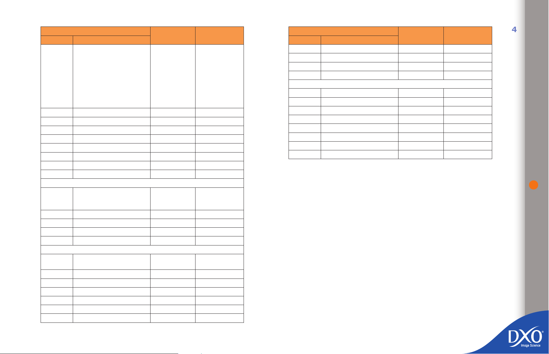
Function
8
6
5
4
3
toc12
7
Scope Action
Hide/Unhide all palettes Tab (1st hit =
Fit on screen Cmd-0 F2
Zoom to 100% Cmd-1 F3
Zoom out Cmd- - CTRL + Add
Zoom in Cmd- = CTRL + Substract
Toggle Grid overlay G CTRL + G
Toggle Information overlay I CTRL + H
Overlay Clip to white A CTRL + W
Overlay Clip to black B CTRL + B
« View » tab
Display corrected and original image side by side or
front/back
Fit on screen M F2
Zoom to 100% Z F3
Zoom out Cmd- - CTRL + Add
Zoom in Cmd- = CTRL + Substract
Tools
Move active slider -
Pointer tool J -
Hand tool SpaceBar SpaceBar
Zoom/move Y -
Crop R -
Dust N -
Horizon E -
Shortcuts
Mac
hide all docked
palettes, 2nd
hit = hide all
docked palettes
+ oating
palettes ; 3rd
hit = show all
palettes)
C CTRL + ALT + B
Shortcuts
Windows
F9
- CTRL + T
ß and à (left
and right arrows)
Function
Scope Action
Force Parallel U -
Rectangle V -
Multipoint WB * -
WB W -
Palettes
Navigation T -
Histogram H -
Preset editor P -
EXIF X -
Light L -
Color K -
Geometry O -
Detail S -
Shortcuts
Mac
Shortcuts
Windows
64
 Loading...