

Page 1

Bulletin E-90-DL8
Series DL8 Process Data Logger
Specifications - Installation and Operating Instructions
Temperature
Sensor
GENERAL
Eliminate traditional paper chart recorders with the Series
DL8 Process Data Logger. This versatile, mulit-channel data
logger monitors and stores up to 32,768 process readings
for later download to IBM compatible computers. Seven
external input channels easily interface with commom
transducer and transmitter outputs. Internal thermistor
measures ambient temperature conditions. The DL200
Windows
(sold separately) makes programming the data logger simple and easy. The Series DL8 Process Data Logger is ideal
for monitoring temperature, relative humidity, pressure,
wind speed, current, voltage and power.
GENERAL INSTALLATION (for all DL Loggers)
The Trendreader software must be installed on your computer prior to the use of any data logger described in this
reference.
NOTE: For additional information on graph manipulation,
custom equations, modern setup, and sample rate tables,
consult the Trendreader software manual.
™
(Trendreader) software and connecting cable
Input Jack for Interface Cable
PHYSICAL DATA
No. of Channels: Eight; One
for internal thermistor and
seven for external analog
inputs.
Accuracy: ±1% of full scale.
Internal Thermistor Range:
-40 to 158°F (-40 to 70°C).
Memory Size: 32,768 readings.
Sampling Methods:
Continuous (First-in, First-out)
or Stop when full (Fill-thenstop).
Sampling Rates: Selectable
from 8 seconds to once every
5 days.
Resolution: 8 bits (1 in 256).
Power: Built-in 3.6V Lithium
battery.
Power Consumption: 5-10
µA.
Clock Accuracy: ±8 seconds per day plus one sampling interval.
Security
Eyelet
2.95
[75]
0.656
[17]
Input Impedance:
0 to 200 mV: > 20MΩ.
0 to 2.5 V: > 20MΩ
0 to 5.0 V: 20KΩ
0 to 10.0 V: 40.9KΩ
0 to 25 mA: 100Ω
Maximum Input Voltage: All
Voltage channels: ±40 V,
reverse polarity protected. All
Current channels: ±7 V,
reverse polarity protected.
Ambient Operating Temp:
-50 to 160°F (-45 to 70°C), 0
to 95% RH, non-condensing.
Connection: Removable
screw terminal.
Computer Requirements:
IBM compatible 386 or above
and Windows
with 2 mB RAM and 2 mB
hard drive disk space, one serial port.
Housing: Noryl
Weight: 5 oz. (110 g).
3.375
[9.5]
™
3.1 or later
™
Magnetic
Strip
0.45
[12]
Setup
To setup your datalogger you must first have Trendreader
software installed and running on your computer. You can
then configure your logger with various options by plugging
into your computer via the interface cable. From the
Communicate menu, choose Preferred Logger SR+. To
access the logger window, double click on the logger icon
or click Communicate on the menu bar and choose the
highlighted Open COM from the menu.
DWYER INSTRUMENTS, INC.
P.O. Box 373 • Michigan City, IN 46361-0373, U.S.A. Fax: 219/872-9057 e-mail: info@dwyer-inst.com
SERIES DL8 PROCESS DATA LOGGER MODELS & EQNS
Model No.
DL8
DL81
Input Type
0 to 2.5 VDC
0 to5 VDC (2 channels)
0 to 10 VDC
0 to 200 mV DC
0 to 25 mA DC (2 channels)
All channels 0 to 25 mA.
Equation #
7
18
17
19
6
6
Table 1
Phone: 219/879-8000 www.dwyer-inst.com
Page 2
If more than one logger icon appears on the screen or more
than one Open COM is highlighted on the Communicate
menu, this means you have more than one COM port available on your computer. Choose the port that the particular
logger is connected to.
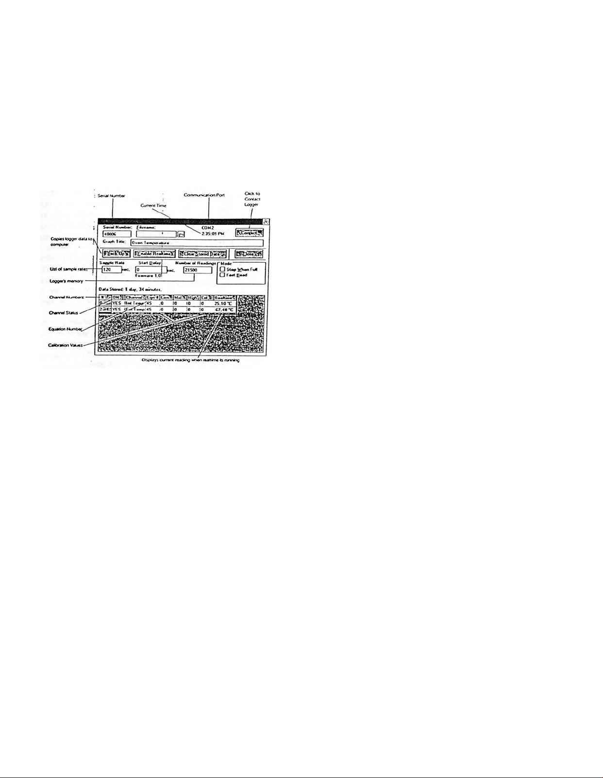
The logger window will display the serial number of the logger Trendreader software is communicating with. See
Figure 1. To contact another logger connected to the compute. 1. Double-click the serial number displayed to highlight it. 2. Type the serial number of the logger you want to
contact. 3. Click the Contact button.
Enabling and Disabling Channels
Enabling a channel activates that channel and it will continually record and store readings in memory. In the channel
ON column, Yes means the channel is active, No means it
is not. Click on the channel being changed to toggle
between yes and no. Disable any channels not required to
conserve memory space.
Equation Numbers
Equations are calculations the software uses to convert raw
logger data to understandable units. Refer to page one
(Table 1) for the appropriate equation number.
To see a list of standard equations available, double click
one of the equation numbers in the Eqn column. The Select
an Equation dialog box will appear, enabling you to scroll
through the standard equations. If you want to choose one
of the equations on the list, click it to highlight, and click
Accept (or Enter). You can also choose an equation by typing the number in the selected Equation Number box and
clicking Accept (or Enter).
Custom equations can be created and assigned to specific
logger channels. For additional information on creating custom equations, please refer to the instruction manual included with the Trendreader software.
Figure 1
Filename
You cannot name the file during setup. Name the file when
you are backing up the logger.
Current Time
Make sure the current time is correct. To change the time,
access the Program manager on your computer and follow
instructions in your computer setup manual.
Stop When Full and Continuous Mode
The logger can be set to stop taking readings when the
memory is full, or to continue to take readings when the
memory is full. To choose the first option, click the box in
front of Stop When Full so that there is an “X” in it. To
choose the continuous mode, click the box in front of Stop
When Full so there is no “X” in it. The logger will continue to
take readings when the memory is full, discarding the oldest reading as it records new readings.
Stopping Realtime
When the logger window is opened, the logger is operating
in realtime mode, which means current readings are being
displayed in the window. Before changing any settings, click
Edit Setup.
Clearing Stored Data
To empty stored data, click Clear Stored Data.
Calibrations
The calibration values displayed in the low, med, high
columns are factory set and match the sensor applied.
Viewing Realtime Readings
The realtime function allows the user to view measurements
as they are being recorded. Viewing current readings can
be useful when monitoring remote loggers by modem. In
realtime mode, the logger reads and displays the variable
every 8 seconds. If the sample rate is greater than 8-seconds, the average value for the sample interval is stored
(based on 8-second readings).
Do not leave realtime running if you want to perform other
tasks in Trendreader or if you want to switch to another
Windows™application. The operation of Trendreader of
other Windows™program will be slowed considerably with
realtime running. To stop or start realtime, click the Edit
Setup button. Stopping realtime has no effect on the logger’s information gathering.
Units of Measure
The units of measure can be changed to fit your particular
needs. To change the units displayed in Realtime and on the
logged data choose the Options menu, highlight the parameter being measured. The units appropriate for that particular parameter will be displayed in the units window.
Select the box corresponding to the desired units of measure and press Enter.
Page 3

When viewing in realtime, the new units will be displayed at
the next update interval. The standard unit of measure will
be designated with a 1 in the Scale column. When selecting a different unit of measure, make sure the conversion
from the standard is correct.
Choosing a Sample Rate
The sample rate is the frequency that the logger takes readings. The current sample rate is always displayed. to
change the sample rate: 1. Click the current rate. The sample rate dialog box appears. The dialog box displays current
sample rate, the number of active channels, and the length
of time it will take to fill the memory using the number of
active channels and rate. (To determine the loggers capacity, enable the number of channels required before choosing
a sample rate). 2. Click the down arrow to see available
sample rates from 8 seconds to 8 hours in Continuous and
Stop When Full modes. Scroll if necessary, and click on the
desired rate. In Fast Read mode, sample rates less than 8
seconds are available. 3. Click Accept. The new sample
rate will apply to all active channels. If you do not want to
change the sample rate, click cancel.
Delaying Starting Time
Make sure the correct time is displayed in the logger window before using this function. Once the logger has been
setup, click Save Setup, and the logger will start gathering
data. To delay the start time: 1. Double click in the Start
Delay box to open the Select a Time dialog box. 2. Set the
time and/or date for the logger to start taking readings. 3.
Click Accept. The logger can be set for a delayed start time
of up to two years.
Number of Readings
The maximum number of readings the DL8 logger can store
is 32,768. If fewer readings are desired, change the number
(in increments of 500).
Fast Read Mode
Choose Fast Read Mode when:
1. You need a sample rate of less than 8-seconds, and /or
2. You want to delay the logger’s start time but do not want
to specify the start time until after the logger has been
setup.
Fast Read Mode allows you to choose sample rates from
0.04 seconds (25 readings per second) to 2 minutes. The
sample rate must be in increments of 0.04 seconds. NOTE:
A separate power source is required when using Fast Read
Mode. Power can be supplied from the computer the logger is connected to or a separate battery pack (BP-100). If
using the battery pack, the logger will start taking reading as
soon as the battery is connected.
The logger cannot work in continuous Mode when using
Fast Read Mode. The logger will stop taking readings as
soon as the memory is full. The logger will also interrupt
readings when it is connected to Trendreader software.
To delay start in Fast Read Mode:
1. Set the delay time in seconds in the Start Delay box. Use
this method when the logger will remain connected to a
computer or battery pack.
2. If the battery pack will be connected at a later time, follow this procedure before disconnecting the logger from the
computer: Before clicking Save Setup, set that Delay for
long enough that you can save the setup and disconnect
the logger while it is asleep. The logger must be asleep (on
start delay) when it is disconnected to be able to start taking readings when the battery is connected to it. NOTE: You
must set a minimum start delay of 16 seconds before you
disconnect the logger from the computer. the logger must
be disconnected from the computer within 8-seconds of
setting the delay. If these steps are omitted, the logger will
not start when the battery is connected.
To calculate the number of readings a particular time span
will need, divide the time span by the sample rate (making
sure both are in seconds or minutes). If you are taking readings at 8-second intervals for 24-hours, and need to know
the number of readings, convert 24-hours to seconds
(86400) and divide by the sample rate of 8-seconds to get
10,800 readings. When backing up the logger, it will stop at
the specified number of readings.
Saving Changes
When you have finished setting up your logger, click Save
Setup. A dialog box will appear asking to clear the logger
and save setup. (Setting up a logger erases all the previously gathered data). Click OK.
Do not contact a logger in Fast Read Mode until you are
going to back it up. Contacting the logger will stop it from
taking readings. You can contact a logger by clicking
Contact or by opening the window once it has been closed.
BACKING UP A LOGGER
Copying data from a logger to your computer requires an
IC-100 or IC-200 Interface cable. to backup a single logger
use the IC-100 Interface Module. The IC-200 Interface
Module can be used to backup several loggers. Backing up
a logger can take a number of minutes depending on the
speed of your computer and the amount of data being
transferred.
Page 4
The process can be speed up by selecting the Set Baud
rate, Fastest Available from the Communicate menu. (If you
have problems backing up a logger, try a slower baud rate.
On some computers, choosing the fastest available baud
rate causes timing conflicts. NOTE: The IC-200 module
automatically transmits at 1200 baud and cannot be adjusted.
Backing Up a Logger
From the Communicate menu, choose Preferred Logger
SR+. To access the logger window, double click on the logger icon or click Communicate on the menu bar and choose
the highlighted Open COM from the menu. To backup a logger, click Backup in the logger window. A dialog box
appears showing the baud rate, the serial number of the
logger, and the progress of the backup. (You may cancel
the backup procedure by clicking Cancel).
Figure 2
Opening a Graph after Backup
If you want to view the transferred information as a graph
immediately after backup, open the Options menu in the
main window and make sure a check mark is in front of
Open Graph after Backup. NOTE: See the Trendreader software manual for details on manipulating graphs.
Naming a File
When backup is completed, the Save As dialog box
appears to enable you to name the file. The default name is
always the serial number of the logger. If you want to keep
the logger’s serial number as the filename, click OK. If you
want to give the file a different name, type the new name
and click OK. NOTE: You cannot type anything after the dot
in the Trendreader filename. The three letter extension, is
automatically assigned.
Backing Up Additional Loggers
You can daisy-chain the DL8 loggers together and back
them up one by one. You may want to disable the opening
a graph after backup function when you are backing up
several loggers. If this function is not disabled, a graph will
be opened after backing up each logger, increasing the total
backup time. To disable this function, open the Options
menu and make sure there is no check mark in front of
Open Graph After Backup.
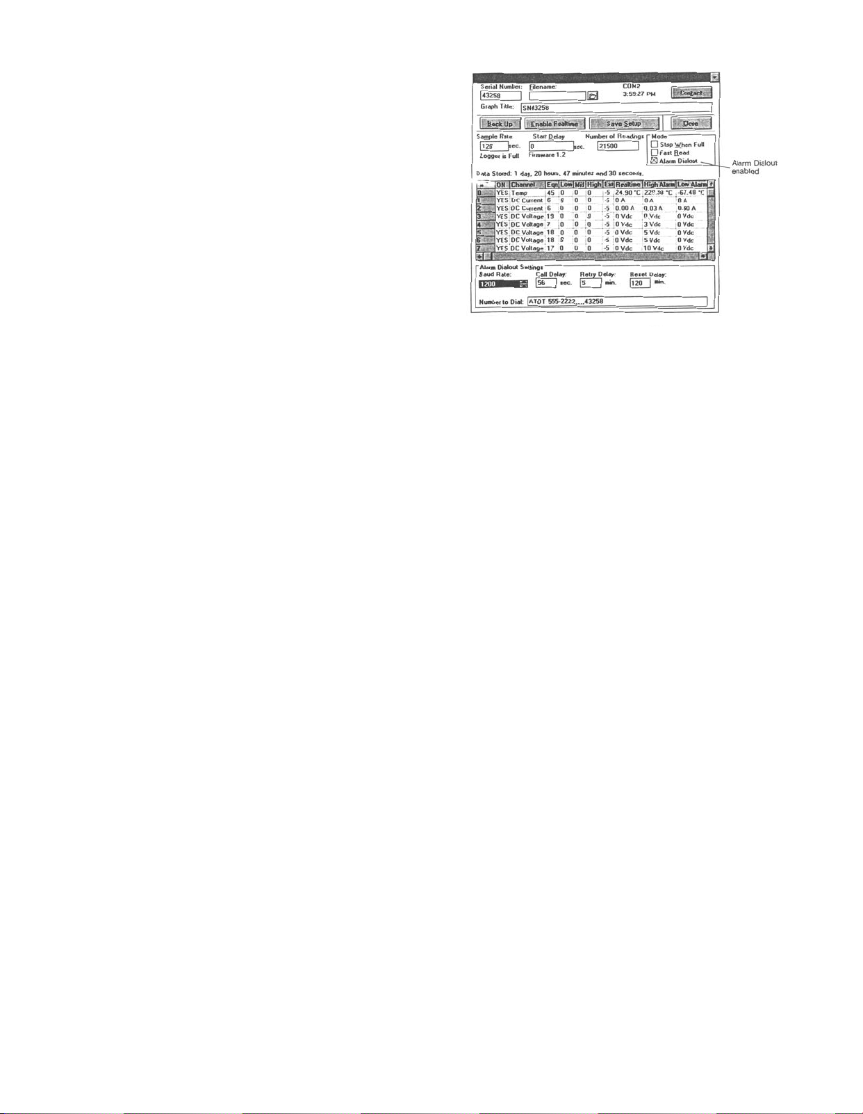
Alarm Dialout is enabled by setting high and low alarm
thresholds, entering the number that is to receive the alarm
call, and sending the setup to the logger. When an alarm
condition occurs, the logger will dial out and leave the
remote site number on the receiver’s telephone caller ID or
on the pager’s display. (Alarm Dialout does not leave a verbal message). To activate Alarm dialout, click Alarm Dialout
in the logger window so that there is a check in the Alarm
Dialout box. A dialog box will appear at the bottom of the
window. See Figure 2.
Setting High and Low Alarm Thresholds
Set high and low alarm thresholds for each active channel
on the logger. Any reading lower than the low alarm threshold or higher than the high alarm threshold will cause the
logger to dial out from the remote site. Set the high alarm to
the highest possible value and low alarm to the lowest possible value if you do not want the alarm activated on that
channel.
Choosing a Baud Rate
Baud rate is a measure of the transmission speed of the dial
commands that the logger sends to the modem. The
default baud rate is 1200, which is reliable and accurate for
most situations. Higher baud rates are available in the baud
rate box.
ALARM DIALOUT
Alarm Dialout enables you to setup the logger at a remote
site so that it will dial a phone number when readings have
exceeded preset alarm thresholds. It can be setup to dial a
telephone or pager. The receiving telephone requires caller
ID to use this feature.
If sending the alarm to a pager, the pager system must
accept touch-tone codes that can be displayed on the
pager.
Entering the Number to Dial
A. Calling a telephone: Remember the telephone must
have caller ID to receive the alarm.
1. Type a dial command in the Number to Dial box.
If the phone line at the remote site has tone dial, type ATDT.
If pulse dial, type ATDP.
2. After the dial command, type the number of the
telephone that is to receive the alarm call.
Page 5

B. Calling a pager: The pager system must accept
touch-tone codes that can be displayed on the pager.
1. Type the dial command ATDT in the Number to
Dial box.
2. After the dial command, type the number of the
pager that is to receive the alarm call.
3. After the pager number and before the identifying code there must be a pause to allow the receiving station to answer. Enter this pause by typing commas. (For
most modems, each comma causes a pause of two seconds).
4. Type a code that will identify the logger. For
example: ATDT 555-2222,,,,,40167, would instruct the logger to dial the pager number and pause for ten seconds,
and then send the serial number of the logger.
Setting Call Delay
Call delay is the length of time that a logger will wait before
dialing out once an alarm condition has occurred. If you do
not want the remote logger to dial out immediately when
one or more of the channels goes into alarm condition, you
can set the Call delay to designate the number of seconds
the logger will wait before dialing.
If the alarm condition does not exist for the entire delay period, the logger will not dial out. If the logger comes out of an
alarm condition during the call delay period, the delay timer
will stop and will start again from zero at the next alarm
event.
Setting Retry Delay
If a remote logger dials out an alarm but cannot get through
(line is busy), it will continue to dial out until connection is
made. Retry delay is the length of time the logger will wait
between unsuccessful attempts. It is recommended to set
the retry dial to 5 minutes. The logger will continue to dial
out after every retry delay time and as long as the alarm
condition exists and has not been acknowledged.
Setting Reset Delay
Reset Delay begins when you acknowledge the alarm by
backing up the logger that has dialed out. Reset Delay
deactivates Alarm Dialout to give time to fix the problem that
caused the alarm. When Reset Delay period has elapsed,
Alarm Dialout will reactivate, and if an alarm condition exists,
the logger will dial out again.
IMPORTANT: If an alarm condition occurs and Reset Delay
has been initiated by the last backup, the logger will wait
until the Reset Delay period is over before dialing out. To
bypass the Reset Delay period (if you have fixed the alarm
problem but time remains on the Reset Delay), click the
Clear Stored Data button and follow the subsequent
prompts.
Sending the Setup to the Logger
After choosing Alarm Dialout settings, setup logger by clicking the Save Setup/Clear Stored Data button and follow the
subsequent prompts.
Responding to Alarm Call
1. When the logger dials out to warn of alarm condition, dial
into the site and backup the logger.
2. Fix the problem that caused the alarm.
3. Reactivate Alarm Dialout by contacting the logger and
clicking Clear Stored Data.
NOTE: Test Alarm Dialout regularly to ensure proper operation.
Fast Read Mode Disabled
Alarm Dialout is not designed to operate in Fast Read
Mode. When Alarm Dialout is enabled, fast Read Mode is
disabled; when Fast Read Mode is enabled, Alarm Dialout
is disabled.
Cold or Humid Environments
The environment the logger will be placed in must be suitable, please refer to the physical data section. If conditions
are not acceptable, consider using a protective enclosure.
For humid environments, the logger can be protected by
placing it in a ziplock plastic bag.
If the logger is used in a cold environment, make sure condensation will not settle on the logger when it is brought
back into a warmer environment. The best way to prevent
condensation is to place the logger in a plastic ziplock bag
and include a dessicant. When you bring the logger back
into the warmer climate, leave the logger in the bag with the
dessicant until the logger has come to equilibrium with the
environment.
Label
If working with more than one logger, label each, identifying
the task and location before you distribute them throughout
a building or system. To do this, simply use shipping tags.
Later, when you retrieve them to graph their data, you will
know what each graph refers to.
Mounting
Use the magnetic backing to conveniently mount the logger
on metal surfaces like ductwork or electrical control cabinets. If concerned about theft, make sure to lock the logger
to a permanent fixture using the special locking tab.
Special mounting methods (using Velcro®fasteners) to
secure the loggers to other surfaces may be used. NOTE:
Do not rely on the logger’s magnetic strip for secure mounting if the surface is uneven, unstable, or above 150°F
(65°C).
Page 6

Keep Track
Be sure to keep record of the locations of each logger. This
will save time in looking for them when the data-gathering is
completed. Also, keep track of when the loggers were put
into service. This will help when producing graphs.
Retrieval
After sufficient time has passed to obtain a representative
profile of data, retrieve the logger and bring it back immediately for analysis. Make sure the logger has a label so it can
be properly identified and differentiated.
Analysis
To analyze the logger, you must first transfer a copy of its
data into your computer. To do this, plug the logger into the
Trendreader interface cable and choose Logger,
Communicate, Backup. After describing the information to
the computer, the data is automatically copied to disk, time
and date stamped, and converted into the appropriate
measurement units. A portion or the entire data set can be
copied.
Each file will initially have the same descriptive title, but you
can use Files, Revise Logger to alter these accordingly. To
view graphs, choose Draw, New and select the appropriate
file. A detailed description of all software functions can be
found in the Trendreader Reference Guide.
4. Connect the power supply adapter to the gender changer.
5. Connect the 6VDC power supply to the adapter.
NOTE: The cable length between the IC-200 and the computer or modem can be extended. Maximum length should
be 500 feet (150 m). Use 22-gauge stranded wire, with two
conductors and a shield.
Identifying Loggers on a Network
Before you can contact a network group of loggers at a site
for the first time, you must name the site and list serial numbers so they can be identified.
1 From the Communicate menu in the main Trendreader
window, choose SR+ Network so that a check mark exists
in front of it.
2. Choose the COM port that the loggers are connected to.
The Logger List dialog box will appear. Site name and logger serial numbers will be entered in this dialog box. See
Figure 3 below.
OPERATING A LOGGER NETWORK
The Series DL8 Dataloggers can be networked to enhance
the monitoring and backup capabilities. Use model IC-200
Interface Module to connect as many as 8 loggers to your
computer simultaneously. The IC-200 Module will allow
backup of a 8 loggers, one after the other, with one command. Realtime data from up to 64 channels (8 loggers with
8 channels) can be displayed on a single screen.
Connecting an IC-200 to the Computer
1. Connect the serial port extension cable’s female end to
the computer’s 25-pin serial port. Use the 9-pin connector
if the computer has a 9-pin port).
2. Connect the cable’s other end to the IC-200 connection
maked “PC”.
3. Connect the power supply adapter to the other end of
the IC-200 (the end marked “modem”).
4. Connect the 6VDC power supply to the adapter.
Connecting an IC-200 to a Modem at a Remote Site
1. Connect the serial port extension cable to the modem.
2. Connect the cable’s other end to the IC-200 connection
marked “modem”.
3. Connect the gender changer to the other end of the IC200 (marked “PC”).
Figure 3
3. In the Site Name box type a unique name for the site and
press Enter.
4. Click in the Serial # Column, type the serial number of
one of the loggers, and press Enter. (The order does not
matter, however, if you click Show All to view realtime readings, the readings will be displayed in the order they were
entered.)
5. If desired, add a description in the Description column
and press Enter.
6. Repeat steps 4 and 5 until all the loggers at the site are
listed.
7. Click Save Changes.
You can now contact any of the loggers listed.
Deleting a Site and its Loggers
1. Highlight the site to be deleted in the Site Name box. To
scroll between sites, click the down arrow.
2. Click Delete. The site name serial numbers and descriptions will be deleted.
3. Click Save Changes.
Deleting One Logger from a List
1. Click in the loggers serial number box to highlight the
number.
2. Click Delete. The serial number and description will be
deleted.
3. Click Save Changes.
Page 7

Viewing Realtime Readings of All Loggers
1. From the Communicate menu in the main Trendreader
window, click SR+ Network until a check mark appears in
the box.
2. Choose the COM port the network is connected to. The
Logger List dialog box will appear.
3. Click Show All. The Network Realtime window will open
displaying each logger’s realtime readings. See figure 4
below. When finished viewing the realtime readings, either
click Close to close the window, or double-click a logger’s
serial number to open that logger’s window.
Figure 4
Contacting a Network Logger
There are three ways to contact a logger on a network:
1. From the Logger List dialog box
2. From the Network Realtime window
3. From the Logger window
SETUP (specifically for the DL8)
This section provides guidelines to follow to get you started
with your DL8.
1. The first step in using your DL8 is to decide what information, or parameters, you want to log. For example, you
may simply wish to replace an existing hard-wired 4-20 mA
chart recorder or, instead, monitor from a special multipletransducer circuit that you have assembled.
2. Determine what sensors, transducers, or transmitters
you need to do the job (if not already present).
3. Modify the channels, externally (using resistors), if
required for maximum resolution (see Customizing Input
ranges).
4. Write an equation to convert the raw readings from the
transducer or circuit you want to monitor into the proper
engineering units you require (for example: converting 4-20
mA signal from a relative humidity transmitter to 0 to 100%
R.H.). For help in writing these equations refer to your
Trendreader Software manual.
Contacting a Logger from the Logger List
Double-click the logger’s serial number (or click the logger’s
serial number and click Contact Logger). The loggers main
window will open.
Contacting a Logger from the Network Realtime
When you have contacted a logger by one of the previous
two methods and you have that logger’s window open, you
can contact another logger on the network by taking the following steps:
1. Click Edit Setup. (See figure 5).
2. Double-click the serial number in the Serial Number box.
3. Type the number of the logger you want to contact.
4. Click the Contact button to open that logger’s window.
NOTE: DO NOT setup networked loggers in the Fast Read
Mode. Any networked logger that is setup in Fast Read
Mode will stop logging as soon as it or any other logger on
the network is contacted.
Figure 5
Figure 6: Using Transducers with Power Supply
5. Decide how you are going to power your transducers (if
required). You can either use a standard power supply and
create a circuit like that shown in Figure 6 or use batteries
(see External Battery Operation) and produce your own selfcontained logging assembly (Figure 7). For this application,
you must activate the internal battery switch.
Figure 7: Using Transducers with a Battery
6. Connect your transducers or transmitters and check
operation through the Logger, Communicate, Realtime
function in the Trendreader Software.
Page 8

Avoiding Ground Loop Problems
Take special care to avoid ground loop problems when you
use your DL8 Process Data Logger. A ground loop can
occur when there is more than one path to ground in your
logger-transducer circuit. Ground loops can damage your
DL8 Process Data Logger as well as your transducers. To
avoid ground-loop problems your DL8 circuit:
• Do not use more than one grounded power sup
ply to power your transducers.
• Do not connect your logger to your computer in
real time readings unless:
• your computer is battery-operated (i.e. not
grounded); or
• your transducer power supply is not grounded.
If you must use more than one grounded power supply in
your circuit, each transducer you use must be isolated. If
you must use non-isolated transducers, then you must use
a Signal Repeater/Loop Isolator between the transducer
output and the DL8 input.
Wiring Notes and Considerations
1. The Series DL8 Process Data Logger has two common
inputs (labeled “-Common”). These are not isolated from
each other and can be used as the “-” connection for the
power supply (or battery) and any of the transducers being
logged by the Series DL8.
2. For permanent applications, wiring connections can first
be made to the Series DL8 removable terminal block. The
terminal block can then be attached (with glue, for example)
to a permanent fixture. When it comes time to analyze data,
the data logger can simply be unplugged from the terminal
block and brought back to your computer. After backing up
the data, the logger can be returned and plugged back into
the terminal block. Logging will then automatically continue.
3. The 2.5 V and 200 mV channels “float” when no connections are made to them. They can thus be expected to
read a positive voltage when left both active and unconnected. When connected, however, they will read the correct input voltage.
4. The “25 mA” channels read positive current only. Make
sure to observe polarity. If you are using both channels
simultaneously, ensure that both 4-20 mA transmitters
source a positive current through the logger to a common
(-).
CHOOSING INPUT CHANNELS
To choose which of the DL8’s seven external input channels
to use for your particular applications and understanding of
resolution is required.
Maximizing Resolution
The resolution of your DL8 Logger is eight bits. This means
that it can resolve analog signals, with a defined range, to
256 discrete steps (2 to the power of 8). When logging from
the 2.5V channel, for example, the DL8 will record digital
values in increments of 2.5 volts divided by 256, or approximately 10 millivolts.
Resolution is usually not a significant factor until you have
logging applications that will produce input signals far less
than that of the range of the logger’s channel itself.
The 2.5V channel will have a resolution of 0.4% over a
range of 0 to 2.5 volts (.01/2.5 x 100) which should be more
than adequate for most applications. If, however, you are
intending to measure signals ranging from 50 to 150 millivolts (with the same 2.5V channel), resolution will be much
coarser (10%). By switching the 50 to 150 millivolt input to
the 200mV channel, resolution can be improved to approximately 1%.
Choosing Input Channels
It is important to maximize resolution when measuring and
recording from the DL8’s current and voltage channels.
Usually you can do this simply by choosing the channels
that match or approximate the input signals you will be
using. The table below lists several possible input signal
ranges and the recommended channels to use. It also lists
alternative channels that can be used to add additional
simultaneous monitoring capability. These alternative channels will, however, require the addition of external resistors
(see Customizing Input Ranges).
Range
of Input
0 to 500 mV
0 to 1.0 V
0 to 2.0 V
0 to 3.0 V
0 to 6.0 V
0 to 20 V
0 to 2.0 mA
4 to 20 mA
0 to 50 mA
0 to 100 mA
In the above table, the Range of Input column lists examples of input signals that you may wish to monitor using
your logger. The Standard Solution column lists the channel
you would normally choose to monitor that particular signal.
In this table, 200 refers to the 200mV channel, 2.5 the 0 to
2.5V channel, 5 to either of the two 0 to 5V channels, 10 to
the 0 to 10V channel, and 25 to either of the two 0 to 25mA
channels. The Alternative Solution column lists other channels that can be used to monitor the same input signals. In
most cases, these channels will need to be fitted with external resistors.
Standard
Solution
2.5
2.5
2.5
5
10
N/A
25
25
N/A
N/A
Alternative
Solution(s)
200
200
200
200
5, 2.5, 200
10, 5, 2.5, 200
200
2.5, 200
25, 5
25, 10
Page 9

Non-Standard Ranges
You may want to use a special transducer or tie in an existing process signal loop that does not match the DL8’s standard input ranges. The following step-by-step procedure
will help you choose which channel is best.
1. Determine the maximum output signal (M) and the zero
offset signal (Z) of the transmitter or circuit you wish to tie
into. For example, a transducer with a specified range of 1
to 6 volts DC will have a maximum output signal of 6 volts
and a zero offset signal of 1 volt. A 4 to 20 milliamp transmitter will have a maximum output signal of 20 mA and a
zero offset signal of 4 mA.
5. To find out in what actual steps (S) your logger will collect
data, first determine the input (I) of your transducer or transmitter. You can do this by subtracting the lowest level input
from the high. A thermocouple transmitter, for example, with
a range of -20° to 600° will have an input span of 620° (600(-20)). A pressure transducer with a range of 0 to 100 psi will
have an input span of 100 psi.
6. To calculate S, measured in the same units as the input
span (I) above, use this equations:
R x 1
S =
100
2. Determine the transducer’s full scale output (F). You can
do this simply by subtracting Z from M. The full scale output of the 1 to 6 volt transducer is 5 volts. The full scale output of the 4-20 mA transmitter is 16 mA.
3. Compare M with the channels available on the logger and
choose a channel with an input equal or greater to this value
(if available). If no such channel exists, then modify one to
suit by referring to the Customizing Input Ranges section.
4. Determine the resolution (R) of the channel you chose in
Step # 2 will be adequate. You can determine this, in percent, by using the following equation:
C x 0.4
R =
Where:
C = the input range of the channel to use (in either
millivolts, volts or milliamps).
F = the full scale output of your transducer (M-Z)
measured in the same units as for C.
R = the resolution expressed in a percentage (%)
of full scale output.
For example, a 0.5 to 2.5 volt transducer connected to the
2.5V channel will be logged with a resolution of 0.5%. A 4
to 20 mA transducer hooked up to the 25 mA channel will
log with a resolution of 0.6%.
F
For example, a 4 to 20 mA Relative Humidity transmitter
with an input span (I) of 90% R.H. and a calculated resolution (R) of 0.6% will record data in steps of 0.54% R.H.
CUSTOMIZING INPUT RANGES
The standard input ranges on the DL8 should be suitable for
most process signal applications, but occasionally you may
require measurement of non-standard input levels where
resolution is a primary concern (see the Choosing Input
Channels section). Ranges can be adapted easily by using
either one or two external resistors. Trendreader Software’s
Expert, Equations function can then be used to scale the
data to the new input levels.
The resistor value that you will require to modify each logger’s input channel is selected by inserting your special
input requirements into a simple equation. The following
sections detail these equations and the method of tying in
these resistors.
10 Volt Channel
The 10 volt channel can be modified to span higher ranges
(greater than 0 volts DC) by adding a single resistor to the
“10V” terminal shown in Figure 8. The value of the resistor
R must be calculated by the following formula based on the
desired voltage input range Ein:
R = (4,090 x Ein) - 40,900
Generally, it is good practice to keep resolution to within 1%
for most applications. However, you may be able to accept
far coarser resolution in some applications and, in others,
require far better. You’ll be able to determine your own
requirements after you’d be become familiar with the results
you can expect with different arrangements. If your requirements demand greater resolution than what you calculated,
then you should set up your inputs with resistors as
described in the Customizing Input Ranges section.
For example, if you wish to measure up to 20 volts, the
resistor value should be:
(4,090 x 20) - 40,900 = 40,900 ohms.
Since you won’t always be able to get the exact resistor
value that you calculated, you can determine the logger’s
actual input range by plugging the value of the resistor (R)
you obtain back into the equation. For example, if the closest resistor you could obtain was 42K ohms, then the actual voltage input range would be:
42,000 + 40,900
Ein=
4,090
= 20.27 volts
Page 10

This value will be needed when it comes time to create your
own custom equation using Trendreader Software’s Expert,
Equations function.
Figure 8: Modifying the 10 volt channel for extended range
You can also easily convert the 10V channel to measure 0
to 100 mA current simply by putting a 100 ohm resistor
(minimum rating: 2 watts) between the “10V” and
“-Common” terminals.
5 Volt Channels
The two 5 volt channels can be modified to span higher
ranges (greater than 5V DC) by adding a single resistor, in
the same way as shown for the 10V channel in Figure 8, to
either, or both, of the two “5V” terminals. The value of the
resistor R must be calculated by the following equation
based on the desired voltage input range Ein:
R = (4,000 x Ein) - 20,000
For example, if you wish to measure up to 20 Volts, the
resistor value should be:
(4,000 x 20) - 10,000 = 70,000 ohms.
Figure 9: Modifying the 2.5 volt channel
Since you won’t always be able to get the exact resistor
value that you calculated, you can determine the actual
input range you’ll have by plugging the value of the resistor
back into the formula:
R + 10,000
Ein=
4,000
This value will be needed when it comes time to create your
own custom equation using Trendreader software’s Expert,
Equations function.
For example, if you wish to measure up to 20 volts, the
resistor value should be:
(4,000 x 20) - 20,000 = 60,000 ohms.
Since you won’t be able to get the exact resistor value that
you calculated, you can determine the actual input range
you’ll have by plugging the value of the resistor back into
the formula:
R + 20,000
Ein =
4,000
You can easily convert either of both 5V channels to measure 0 to 50 mA current by wiring a 100 ohm resistor (minimum rating: 0.5 watts) from the “5V” terminals to common.
2.5 Volt Channel
The 2.5 volt channel can be modified to span higher ranges
(greater than 2.5V DC) by adding two resistors to the input
terminals as shown in Figure 9. The value of the resistor
marked “10K” must be 10,000 ohms ±1%. The value of the
resistor marked “R” must be calculated by the following
equation based on the desired voltage input range (E
in
):
R = (4,000 x Ein) - 10,000
You can easily convert the 2.5V channel to measure 0 to 25
mA current by wiring a 100 ohm resistor from the “2.5V” terminal to common.
200 millivolt Channel
The 200 millivolt channel can be modified to span higher
ranges (greater than 200 mV DC) by also adding two resis-
tors, in the same way as shown for the 2.5V channel in
Figure 9. The value of the resistor marked “10K” must be
10,000 ohms ±1%. The value of the resistor marked “R”
must be calculated by the following formula based on the
desired voltage input range (Ein):
R = (50,000 x Ein) - 10,000
You can also modify the 200mV channel to log current loop
signals with greater sensitivity than the two 25 mA channels. To do this, put a 100 ohm resistor across the “200mV”
and “-Common” terminals and you will be able to log currents from 0 to 2.0 mA with approximately ten times the resolution of the 25mA channels. The equation to use to
determine other current (Iin) ranges, in milliamps is:
200
S =
in
I
Page 11

25 milliamp Channel
The 25 milliamp channel can be modified to span higher
ranges (greater than 25 mA DC) by also adding a single
resistor across the input terminals as shown in Figure 10.
The value of the resistor “R” must be calculated by the following formula based on the desired current input range (Iin):
The internal switch can be activated during exit from setup
session by choosing “Yes” as answer to “Activate the
Logger’s external battery switch?” The battery switch status can be checked in setup menu. If the battery switch is
activated Hi Cal for channel 1 (25mA) reads -5. If the switch
is not activated, this value is 0.
2,500
R =
Iin- 25
Make sure the resistor can withstand at least twice the
power you will be sending it. To calculate this, use the following equation:
2
P = 2 * I
in
* R
Where:
P = Minimum Power Rating of resistor (in watts)
Iin= Maximum amperage expected through resistor
(in Amps).
R = Resistance of Resistor (in ohms).
For example, a 50 ohm resistor calculated to measure currents up to 75mA will require a power rating greater or equal
to 0.56 watts. Therefore, a one watt resistor will be fine.
The switch works by closing eight seconds prior to a reading, remaining closed until the reading is taken, then immediately opening again before repeating the cycle.
It extends battery life by only drawing power, when necessary, to meet the input requirements of the transducer or
transmitter circuit that you want to monitor.
To use the battery switch, the battery’s positive (+) terminal
must be wired to the “+ Battery In” terminal on the data logger (refer to Figure 11). The power to your external transducers will then be available from the “+ Power Out” terminal. The battery’s negative (-) terminal can then be wired to
either of the “-Common” terminals.
Figure 10: Modifying a 25 mA channel
For increased sensitivity at lower current ranges down to
2.5 milliamps, refer to the section for modifying the 200 mV
channel.
External Battery Operation
You can activate a special function on the DL8 designed to
optimize the use of power from external batteries while out
in the field. The battery-saving contacts can provide switching capability to draw power from the battery only when
needed, thus maximizing its life for extended field applications.
The internal battery switch allow you to power external
transducers with a separate battery pack. This capability
makes it easy for you to assemble your own self-contained
data logging kit for long-term in-field use where there is no
convenient power supply receptacle.
Figure 11: Using the Battery Switch
Maximum current that the battery switch can source is
100mA. Battery supply voltage can be from 9 to 25 volts.
Short circuit protection is continuous at 9 volts, but only one
second at higher voltages.
Things you should know about batteries
When using batteries for power your external sensors and
transducers, you should keep in mind a few key points.
1. The rated voltage of a battery only applies to initial use.
Once under load, the voltage will decrease gradually until
completely drained. By knowing how the battery voltage is
affected through use you can make sure that the voltage
requirements of your external transducers will be met. A
good rule of thumb to follow is to exceed the minimum
required input voltage for your transducers by at least two
times (where acceptable).
2. Nickel-Cadmium batteries (rechargeable) self-drain themselves at a rate approximately 1% of their remaining capacity per day. This should be taken into account for extended
logging sessions.
Page 12

Determining how long your batteries will last
To estimate how long your batteries will successfully power
your external sensors and transducers, you will need to
know both the capacity of the batteries as well as the proposed resistance presented to them by the load (your own
transducers).
Battery capacity, usually expressed in milliamperes hours
(mAh), is the total amount of electrical charge a cell can
store or deliver. Unfortunately, most commercially-available
batteries are sold without this information.
As a general guide, most good quality nine volt batteries
have a capacity of approximately 500 mAh. This means, at
an average continuous current draw of 50 mA it will deliver
approximately ten hours of service.
The load you impose on your battery will depend on how
many transducers you intend to have in your logging circuit.
The greater the number of transducers, the greater the
power draw from the battery. If you are logging from a 4 to
20mA transducer, the maximum current it will draw will be
approximately 20mA. If you power it continuously, your 500
mAh battery should not run out until you’d had at least
twenty-five hours of service. Since your transducer probably will not always draw maximum current (12mA might be
a more reasonable figure), you can probably expect up to
forty-two hours of service.
Regulated Voltages
The unstable voltage characteristics of batteries makes
them, by themselves, incompatible for use with transducers
that required a regulated voltage supply. You can, however,
add your own voltage regulator to your transducer circuit to
compensate for this instability (see Figure 12). Voltage regulators are readily available at most electronic parts supply
stores (such as Radio Shack).
Figure 12: Regulating Battery Supply Voltage
Make sure that your supply voltage to your regulator is at
least two volts higher than the level to which you want to
regulate to. To do this, you can easily increase the voltage
of your batteries by hooking them up in series as shown in
Figure 12.
The battery-saving switch contacts can increase the lifetime
of your external batteries significantly. Since the batteries
will be powered only for eight seconds out of every logging
interval, the power draw on the battery will be reduced considerably.
Example
Problem: You want to log pressure once every thirty minutes from a 0 to 300 psig transducer. The output of the
transducer is 4 to 20mA. The excitation voltage is listed at
between 9 and 40 volts DC.
Solution: From this information we know that a 4 mA signal will represent 0 psig and a 20 mA signal will represent
300 psig. Since the minimum excitation voltage is 9 volts,
we should supply at least 18 volts initially from our batteries.
We can do this by simply connecting two nine volt 500 mAh
batteries in series.
Without the battery-saving switch enabled, our minimum
expected battery life would be approximately twenty-five
hours. With the switch enabled, and thus closing only eight
out of every 1,800 seconds (or thirty minutes), the life will be
extended by a factor of 225 (or 1800/8). This means that we
should be able to log from this transducer for over 5,625
If the wires between the voltage regulator, batteries, and
transducers are long (more than a few inches) the regulator
may oscillate and produce an unstable voltage. You can
correct this by connecting one 0.1 microfarad capacitor to
each of the regulator’s outside pins then wiring them to the
regulator’s center pin. Make sure to keep the capacitor
leads as short as possible.
MAINTENANCE
No routine maintenance is required on the Series DL data
loggers. Periodic checks of connections and mounting is
recommended. Please contact Dwyer Instruments, Inc.
before returning unit for repair to review information relative
to your application and obtain a return authorization number. When returning a product to the factory, carefully package and ship freight prepaid. Be sure to include a complete
description of the application and problem and identify any
hazardous material used with the product.
©Copyright 1999 Dwyer Instruments, Inc Printed in U.S.A. 2/99 FR R1-443087-00
DWYER INSTRUMENTS, INC.
P.O. Box 373 • Michigan City, IN 46361-0373, U.S.A. Fax: 219/872-9057 e-mail: info@dwyer-inst.com
Phone: 219/879-8000 www.dwyer-inst.com
 Loading...