

Dwt SBM-1050 DT User Manual [ru]

D
CZ
SK
PL
RO
BG
S
IS
MT
LV
LT
EST
BY
UA
MD
RU
KZ
KS
AZ
TR
DWTs Deutsch Werkzeugtechnik Systems GmbH,
Hohenzollerndamm 58, 14199 Berlin, Deutschland
DWT Trade Company / S.C. ISKRA S.R.L., c/o CENTRUM
LOGISTICS S.R.L., Şos. Borşului Nr. 40, 410605 Oradea, România
ДВТ БОЛКАН ООД, 9000 гр. Варна, Западна промишлена зона,
Husasmiðjan Holtagarðar,112 Reykjavik, Iceland
"Riteks A" SIA Viskaļu 3, Rīga ,LV-1026, Latvijas valsts
ул. К.Либкнехта 68-1108, 220036 Минск, Беларусь
ул.Матлахова 1 а, UA - 49064 Днепропетровск, Украина
119530, Россия, Москва, Очаковское шоссе, д. 32
Республика Казахстан, г. Костанай, ул. Целинная, 4
ОсОО "ОлАп-Техно", Республика Кыргизстан,
Bicer Makine San. ve Tic.Ltd. Sti Perpa Ticaret Merkezi
B-Blok Kat:8 No: 1015 Okmeydanı / Istanbul TURKIYE
Garland distributor s.r.o.,
Hradecká 1136, 50601 Jičín, Czech republic
MILAN HABANEK, UNI servis HAMIL,
Legionárska č. 30 91100 Trenčin, Slovakia
ul. Dereniowa 52, 02-776 Warszawa, Polska
БАЗА НОВА, Склад №6, BULGARIA
Munkarpsvägen 19, 243 32, Höör, Sverige
Sir Paul Boffa Avenue, Paola PLA02, Malta
Laisvės pr.31, LT-04340 Vilnius, Lietuva
Punane 1, 13620 Tallinn, Estonia
str.Ismail 50, 2001 Chişinău, Moldova
720031, г. Бишкек, ул. Горького 1
Bakы, Qaheri, Babek Prospekti 25
HANMAR,
VERKTYGSNILSSON KB,
Magnetic Services Ltd.
UAB "BALIMPEKSAS",
Europanoraam OÜ,
ОДО "Планета ДВТ",
ООО "Эдиссон",
COMELECTRO S.R.L.,
ООО "Мир-ДВТ",
ТОО "Костанай DWT",
Quliev Meherram, Azerbaycan,
IR
SY
JO
IL
KSA
ET
LY
[030] 3062019
[030] 88681066
[42] 493522904
[42] 493523523
[040] 359808510 [040] 359808511
[359] 52511339 [359] 52511338
[0413] 557440
[076] 8195574
[017] 2135195
[017] 2135260
[0562] 360504
[0562] 360506
[3142] 393909
[3142] 395333
[090] 2122105763
[090] 2122105716
[21] 66709005
[21] 66720842
[04] 657821
[05] 505205317
[01] 4080556
[01] 4083468
[21] 3608763
[21] 6311150
[030] 3062039
[42] 493522916
[032] 6402933[032] 6522688
[022] 6434040[022] 6433063
[0413] 557441
[354] 5253000[354] 5253254
[21] 802161[21] 676529
[371] 7185399[371] 7545541
[85] 2499280[85] 2444077
[372] 6018727 [372] 6018799
[017] 2087894
[0562] 360504
[22] 542351 [22] 271253
[095] 7853689[095] 7853689
[3142] 395854
[312] 559083[312] 559082
[412] 4481438[412] 4475581
[090] 2122105771
[21] 66709279
[11] 44686606 [11] 2246171
[6] 4772514[6] 4700772
[04] 6469421
[01] 4083627
[045] 3304551[045] 3313065
[21] 3600183
dwtsys@web.de
garland@garland.cz
uni-servis@stonline.sk
hanmar@hanmar.pl
dwt.romania@gmx.net
dwtbolkan@web.de
ban@telia.com
jono@husa.is
mpace@keyworld.net
riteks.a@apollo.lv
balimpeks@is.lt
info@europanoraam.ee
minsk@dwtsys.de
dwt@eds - group.dp.ua
comelectro@yandex.ru
info@dwt.su
dwt@nm.ru
kyrgyzstan-dwt@meil.ru
polad1000@azuni.net
dwtturkey@yahoo.com
acharabzar@hotmail.com
miakcorp@mail.sy
jetco@next.jo
lefofhahoresh@barak.net.il
htmest@atheer.net.sa
mubaagar_2@hotmail.com
info@assendan.com
TN
MA
EAK
UNIVERSITY WAY, NAIROBI, KENYA P.O.BOX 635.00100
BR
R.Albina Kogus Piazera, 80 Jaraguá do Sul-SC BRASIL cep 89.260-255
PE
56 Rue Mansour El Abidi Maarif,
DWT CO. AFRICA LTD WINDSOR HSE, 4-th Floor,
Casablanca 02, Morocco
DWT DO BRASIL FERRAMENTAS LTDA.,
JR. CUZCO 819, CERCADO DE LIMA, PERU
LONGHENG S.A.C.
[73] 474866
[73] 438264
[022] 255778
[022] 993932
2 3 4 5 6
[73] 474867
[022] 235360
[245] 2 242725[245] 2 242725
[47] 3704842[47] 2731818
[511] 4280102[511] 4270752
egem.tunisia@topnet.tn
quincaillerie_taourirt@hotmail.com
f.m.kea@gmx.de
dwtbrasil@dwt.com.br
longheng@telefonica.net.pe
7

500
1050
035411
021070
SBM-1050 DT
1050
030508
020646
BM-1050 DL
9.00
0-900 /
0-2500
600
9.00
0-550
40000
14400 /
3-16
1/8"-5/8"
1,5-13
1/16"-33/64"
16
5/8"
3,40
60 / 40
2-23/64"/1-37/64"
40
13
33/64"
1-37/64"
7.50
20 / 16
25/32" / 5/8"
3,20
7.05
92,00
/ II / II
87,00
10,68
103,00
2,20
98,00
610
1050
030461
020462
SBM-1050 VT
1050
030454
020455
SBM-1050 VS
810
030430
020431
SBM-810 VT
810
030638
020639
SBM-810 V
810
030423
020424
SBM-810 VS
750
030621
020622
SBM-750 V
750
030409
020400
SBM-750 VS
600
030386
020387
SBM-600 VS
500
030379
020370
SBM-500 VS
9.00
0-2880
0-1200 /
600
9.00
0-1700
430
6.80
0-2800
0-1000 /
450
6.80
0-2500
450
6.80
0-2500
390
6.30
0-2800
390
6.30
0-2800
255
5.00
0-2800
210
5.00
0-2800
46080
19520 /
27200
44800
16000 /
40000
40000
44800
44800
44800
44800
1,5-13
1/16"-33/64"
1,5-13
1/16"-33/64"
1,5-13
1/16"-33/64"
2-13
1/16"-33/64"
1,5-13
1/16"-33/64"
2-13
1/16"-33/64"
1,5-13
1/16"-33/64"
1,5-13
1/16"-33/64"
1,5-13
1/16"-33/64"
13
40 / 30
33/64"
1-37/64" / 1-3/16"
30
13
33/64"
1-3/16"
13
40 / 30
33/64"
1-37/64" / 1-3/16"
40
13
33/64"
1-37/64"
40
13
33/64"
1-37/64"
30
13
33/64"
1-3/16"
13
30
33/64"
1-3/16"
30
13
33/64"
1-3/16"
30
13
33/64"
1-3/16"
6.83
3,10
20 / 16
25/32" / 5/8"
16
5/8"
6.61
3,00
2,80
6.17
20 / 16
25/32" / 5/8"
16
5/8"
2,50
5.51
16
5/8"
2,50
5.51
16
5/8"
5.07
2,30
16
5/8"
2,30
5.07
13
2,10
4.63
33/64"
13
2,10
4.63
33/64"
91,00
90,00
96,00
96,00
96,00
90,00
90,00
93,00
/ II / II / II / II / II / II / II / II / II
93,00
6,22
105,00
7,03
104,00
3,20
107,00
20,30
107,00
20,30
107,00
2,90
104,00
2,90
104,00
7,52
104,00
7,52
104,00
400
180
3.30
002000
001461
BM-400 VS
[W]
[W]
[127 V ~50/60 Hz]
[230 V ~50/60 Hz]
Elektrowerkzeug - technische Daten
Bestell-Nummer
Bohrmaschine / Schlagbohrmaschine
Ausgangsleistung
Nennaufnahme
0-2700
-1
[min ]
[Аmps]
Stromstärke
Leerlaufdrehzahl
-1
[min ]
Schlagbohren
Schlaganzahl
Zahnkranzbohrfutter
0,8-10
1/16"-25/64"
[Zoll]
[mm]
Schnellspannfutter
Futterspannbereich
Rechts- / Links-Lauf
Drehzahlregelung
20
25/32"1025/64"
[Zoll]
[Zoll]
[mm]
- Holz
[Zoll]
[mm]
[mm]
- Stahl
- Beton
Bohrleistung:
/ II
1,50
3.31
[kg]
[lbs]
Gewicht
76,00
[dB(A)]
Schalldruck
Schutzklasse
2,30
90,00
2
[m/s ]
[dB(A)]
Schallleistung
Beschleunigung
Deutsch
8

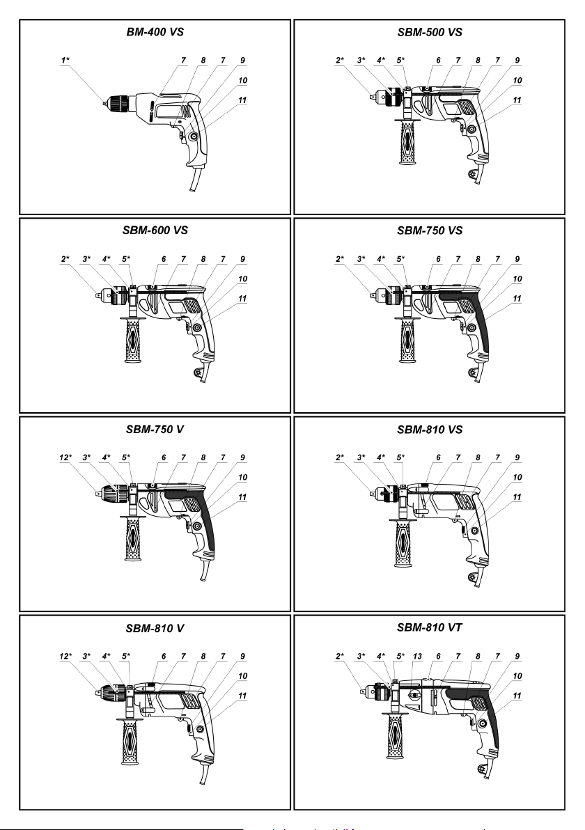
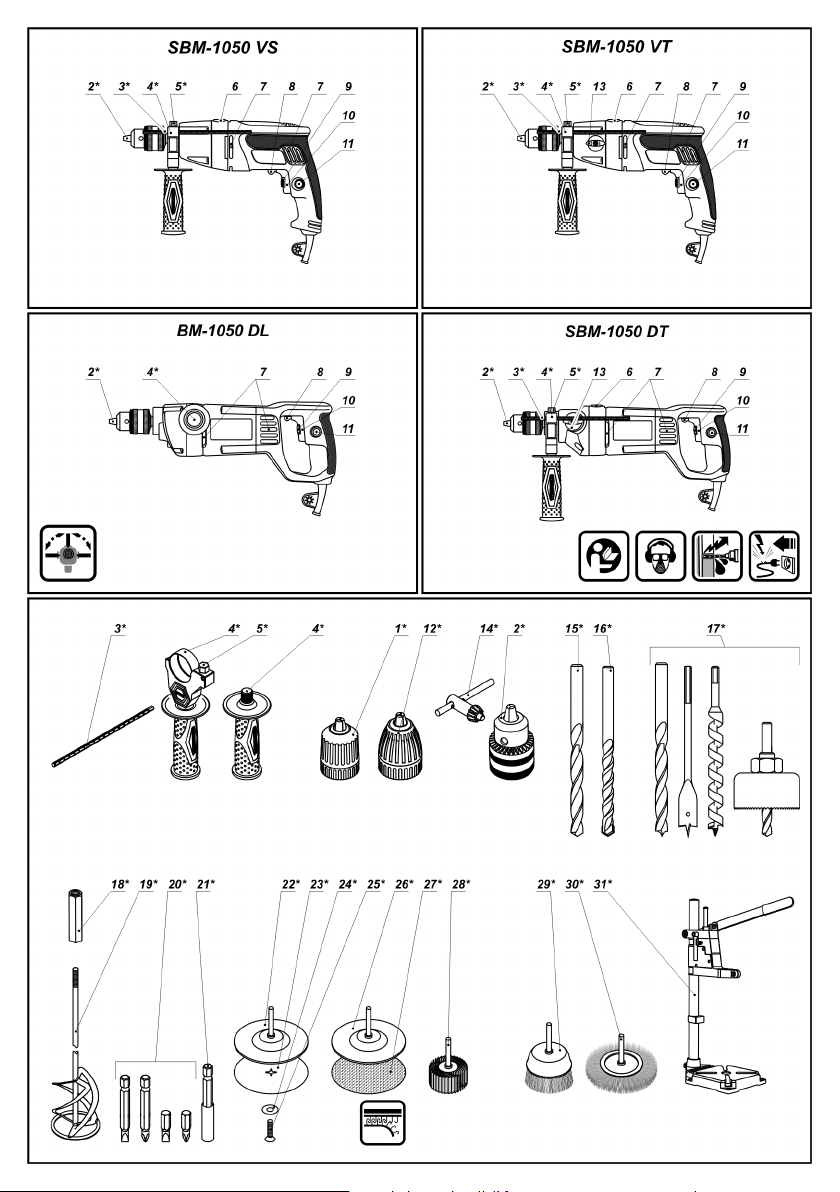
Einzelteile
Bestimmungsgemäßer Gebrauch
1 Schnellspannfutter *
2 Zahnkranzbohrfutter *
3 Tiefenanschlag *
4 Zusatzgriff *
5 Klemmschraube *
6 Umschalter "Schlagbohren / Bohren"
7 Lüftungsschlitze
8 Drehrichtungsumschalter
9 Stellrad Drehzahlvorwahl
10 Ein / Ausschalter
11 Feststellknopf für Ein- / Ausschalter
12 Schnellspannfutter (mit Sicherung) *
13 Drehzahlstufenschalter
14 Bohrfutterschlüssel *
15 Metallbohrer *
16 Betonbohrer *
17 Holzbohrer *
18 Kupplung *
Rührflügel
19 *
20 Schraubendreher-Bit *
21 Magnethalter *
22 Gummi-Schleifteller *
23 Schleifpad *
24 Scheibe *
25 Schraube *
26 Gummi-Schleifteller (Klettverschluss) *
27 Schleifpad (Klettverschluss) *
28 Fächerschleifscheibe *
29 Topfbürste *
30 Rundbürste *
31 S tän der f ür sta tio när e Bef est igu ng d es
Elektrobohrers *
32 Blindverschluss *
33 Schraube *
* Zubehör
Abgebildetes oder beschriebenes Zubehör gehört
teilweise nicht zum Lieferumfang.
Herzlichen Glückwunsch!
Sehr geehrter Kunde!
DWT ist von der hervorragenden Qualität seiner
Produkte überzeugt und gibt umfassende Garantien.
Unser Ziel ist es, hochwertige Elektrowerkzeuge zu
erschwinglichen Preisen anzubieten. Wir hoffen, dass
Ihr neues Elektrowerkzeug Ihnen lange Jahre gute
Dienste leisten wird. Nähere Informationen über unsere
E le k t r o w er k z e ug e s o w ie ü b er u n s e r e
Serviceleistungen finden Sie auf unseren Webseiten:
www.dwtsys.de und www.servicedwt.com.
Das Team von DWT.
Deutsch
Elektrobohrer oder Schlagbohrer werden zum Bohren
in Stahl, Holz und keramische Stoffe verwendet. Das
Elektrowerkzeug kann dank Drehzahlregelung und
Drehrichtungsumschaltung auch als Schraubendreher
benutzt werden.
Durch Verwendung von zusätzlichem Zubehör und
zusätzlicher Ausstattung kann der Einsatzbereich des
Werkzeuges erweitert werden.
Es ist möglich, das Werkzeug fest zu montieren (mit
speziellem Zubehör).
[SBM-500 VS, SBM-600 VS, SBM-750 VS, SBM-750 V,
SBM-810 VS, SBM-810 V, SBM-810 VT, SBM-1050 VS,
SBM-1050 VT, SBM-1050 DT]
Die aufgeführten Elektrowerkzeugmodelle können zum
Schlagbohren in Mauerwerk, Beton und ähnlichen
Materialien verwendet werden.
[BM-1050 DL]
Das Elektrowerkzeug ist auch zum Mischen von
pul v rig e m Baum ater ial wie Kal k, Zem e nt,
Gipsmischungen sowie zum Verrühren von Farben,
Lacken und ähnlichen Materialien ohne Lösungsmittel
geeignet.
Zubehör
Sie können das empfohlene DWT Zubehör auf der Seite
Nr 150-156 der Anleitung finden. Die breite Auswahl des
Zubehörs wird Ihnen ermöglichen, Aufgaben jeglicher
Art effektiv zu erledigen.
Sicherheitshinweise zum Gebrauch
des Schlagbohrers
Den Motor nicht unter Last anhalten.
Achten Sie auf sicheren Stand und halten Sie das
Werkzeug fest mit beiden Händen.
Das Entfernen von Spänen bei laufendem
Elektrowerkzeug ist strengstens verboten.
Vergewissern Sie sich vor Beginn der Arbeiten, wo
Elektro-, Gas- und Wasserleitungen verlegt sind. Eine
Beschädigung von elektrischen Leitungen oder
Telefonleitungen kann Leben und Gesundheit des
Bedieners ernsthaft in Gefahr bringen.
Falls sich das Durchtrennen von Netzleitungen im
Arbeitsplan nicht vermeiden lässt, die Netzleitungen
unbedingt vorher abschalten.
Achten Sie während der Arbeit auf das Netzkabel, es
sollte immer hinter Ihnen liegen. Lassen Sie nicht zu,
dass es sich um Ihre Arme oder Beine wickelt.
Erleichtern Sie sich die Arbeit, indem Sie nur scharfe,
intakte Bohrer verwenden.
9
Jegliche Manipulation an den Bohrern sowie die
Verwendung von Adaptern und Zubehörteilen, die nicht
für das Elektrowerkzeug konzipiert sind, ist strengstens
untersagt.
Wenden Sie beim Bohren keinen übermäßigen Druck
an, andernfalls kann der Bohrer blockieren oder der
Motor wird überlastet.
Achten Sie darauf, dass der Bohrer nicht im Material
blockiert. Niemals versuchen, festsitzende Bohrer
mithilfe des Elektrowerkzeugs zu lösen. Andernfalls
kann das Elektrowerkzeug Schaden nehmen.
Das Herausschlagen eines festsitzenden Bohrers mit
einem Hammer oder einem anderen Gegenstand ist
strengstens verboten - die Bedienperson oder
unbeteiligte Dritte könnten von umher fliegenden
Metallteilen verletzt werden.
Vermeiden Sie ein Überhitzen des Werkzeugs durch
ununterbrochenes Arbeiten.
Montage und Einstellung der
verschiedenen Komponenten des
Elektrobohrers
Vor jeglichen Arbeiten am Elektrowerkzeug den
Netzstecker ziehen.
Bei Montieren von Komponenten keine
Gewal t anwe nd e n. Ü bermä ßi g es
Anziehen von Schraubverbindungen oder
-t eilen kann d as S ch raubgewinde
beschädigen.
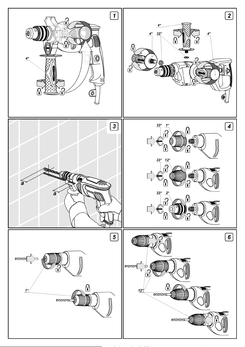
Zusatzgriff
[SBM-500 VS, SBM-600 VS, SBM-750 VS, SBM-750 V,
SBM-810 VS, SBM-810 V, SBM-810 VT, SBM-1050 VS,
SBM-1050 VT, BM-1050 DL, SBM-1050 DT]
Halten Sie das Werkzeu g beim Arbei ten am
Zusatzhandgriff 4 so können sie es bequem und sicher
führen.
Der Zusatzhandgriff 4 lässt sich individuell verstellen.
[SBM-500 VS, SBM-600 VS, SBM-750 VS, SBM-750 V,
SBM-810 VS, SBM-810 V, SBM-810 VT, SBM-1050 VS,
SBM-1050 VT, SBM-1050 DT]
Den Zusatzhandgriff 4 wie in Abb. 1 gezeigt lösen.
Den Zusatzhandgriff 4 in die gewünschte Position
drehen.
Den Zusatzhandgriff 4 wie in Abb. 1 gezeigt
festziehen.
Tiefenanschlag
[SBM-500 VS, SBM-600 VS, SBM-750 VS, SBM-750 V,
SBM-810 VS, SBM-810 V, SBM-810 VT, SBM-1050 VS,
SBM-1050 VT, SBM-1050 DT]
Der Tiefenanschlag 3 dient dazu, eine bestimmte
Bohrlochtiefe vorzugeben (siehe Abb. 3).
Die Klemme 5 lösen.
Die gewünschte Bohrlochtiefe am Tiefenanschlag 3
einstellen.
Die Klemme 5 festziehen.
Montage / Demontage des Schnellspannfutters
[BM-400 VS, SBM-750 V, SBM-810 V]
Schnellspannfutter 1 oder 12 auf die Welle des
Elektrowerkzeugs aufschrauben (siehe Abbildung 4).
Schnellspannfutter 1 oder 12 auf der Welle des
Elektrowerkzeugs sichern, indem Sie die Schraube 33
festziehen. Vorsicht: die Schraube 33 hat ein
Linksgewinde. Zuvor müssen die Spannpratzen des
Schnellspannfutters 1 oder 12 soweit auseinander
geschoben werden, dass die Schraube 33 festgezogen
w e r d e n k an n. D a z u d as V o r d e r te il d e s
Schnellspannfutters 1 oder 12 mit der Hand im
Gegenuhrzeigersinn drehen.
Zur Demontage des Schnellspannfutters 1 oder 12 in
umgekehrter Reihenfolge vorgehen.
Montage / Demontage des Zahnkranzfutters
[S BM-500 VS, SBM-600 VS, SB M-750 VS ,
SBM-810 V S, SBM-81 0 VT, SBM-1050 VS,
SBM-1050 VT, BM-1050 DL, SBM-1050 DT]
Z a h n k r an zfu t t e r 2 a u f d ie W e l l e d es
Elektrowerkzeugs aufschrauben (siehe Abbildung 4).
Z a h n k r a n z f ut ter 2 a uf d e r W el le d e s
Elektrowerkzeugs sichern, indem Sie die Schraube 33
festziehen. Vorsicht: die Schraube 33 hat ein
Linksgewinde. Zuvor müssen die Spannpratzen des
Schnellspannfutters 2 soweit auseinander geschoben
werden, dass die Schraube 33 festgezogen werden
k a n n . D azu d i e S pa nnpratzen m i t de m
Bohrfutterschlüssel 14 lösen und dann das Spannfutter
des Z a hnk ran z fut ter s 2 m it der H a nd im
Gegenuhrzeigersinn drehen.
Zur Demo nta ge des Zahn kranzfut ter s 2 in
umgekehrter Reihenfolge vorgehen.
[BM-1050 DL]
Den Zusatzhandgriff 4 wie in Abb. 2 gezeigt lösen.
Schraubstopf en 32 he rau sne hmen und den
Zusatzhandgriff 4 in das Gewindeloch einschrauben.
Den Schraubstopfen 32 in die frei gewordene
Bohrung einsetzen.
Deutsch
Montage / Ersatz der Werkzeuge
Bohrer werden im längeren Betrieb heiß.
Beim Ausbau von Bohrern deshalb
unbedingt Handschuhe tragen. Auch
beim Ein- und Ausbau von Drahtbürsten
empfiehlt es sich, Handschuhe zu tragen.
10

[BM-400 VS] Schraubendreher-Bit
Das Modell ist mit dem Schnellspannfutter 1
ausgestattet, sodass Sie Werkzeuge rasch und ohne
Schlüssel ein- und ausbauen können.
Spannpratzen des Schnellspannfutters 1 so weit
auseinander ziehen, dass ein Werkzeug montiert oder
ausgetauscht werden kann. Dazu das Vorderteil des
S c h n e l l spannfutte rs 1 m it d er H and i m
Gegenuhrzeigersinn drehen (siehe Abbildung 5).
Montieren Sie das Werkzeug oder tauschen Sie es
aus.
Vo rde r tei l des S c hne lls pan n fut ter s 1 i m
Uhrzeigersinn drehen, um das eingesetzte Werkzeug
zu sichern. Dabei das Werkzeug nicht verdrehen.
[SBM-750 V, SBM-810 V]
Diese Modell sind mit einem Schnellspannfutter (mit
Sicherung) 12 ausgestattet, sodass Sie Werkzeuge
rasch und ohne Schlüssel ein- und ausbauen und
zugleic h - im Ver gleic h zu he rkömm liche n
ungesicherten Schnellspannfuttern - sicher befestigen
können.
D i e K u p p l u n g i m h i n t e r e n T e i l d e s
Schnellspannfutters (mit Sicherung)
bis sie einrastet (siehe Abbildung 6).
Spannpr atzen des Schn ellsp annfutt ers ( mit
Sicherung) so weit auseinander ziehen, dass ein
Werkzeug montiert oder ausgetauscht werden kann.
Dazu das Vorderteil des Schnellspannfutters 12 mit der
Hand im Gegenuhrzeigersinn drehen.
Montieren Sie das Werkzeug oder tauschen Sie es
aus.
Vorderteil des Schnellspannfutters (mit Sicherung) 12
im Uhrzeigersinn drehen, um das eingesetzte
Werkzeug zu sichern. Dabei das Werkzeug nicht
verdrehen.
Zum Einrasten der Sicherung die Kupplung im hinteren
Teil des Schnellspannfutters (mit Sicherung) 12 nach
vorne schieben, bis sie einschnappt.
[SBM-500 VS, SBM-600 VS, SBM-750 VS, SBM-810 VS,
SBM-810 VT, SBM-1050 VS, SBM-1050 VT, BM-1050 DL,
SBM-1050 DT]
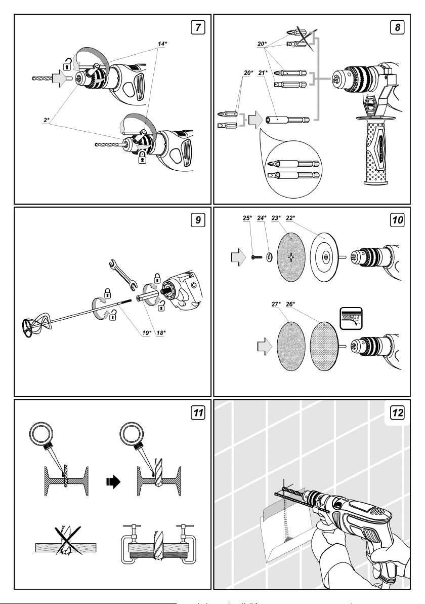
Spannpratzen mit dem Bohrfutterschlüssel lösen,
das Spannfutter des Zahnkranzfutters 2 mit der Hand im
Gegenuhrzeigersinn drehen (siehe Abbildung 7), bis die
Spannpratzen soweit auseinander sind, dass ein
Werkzeug montiert oder ausgetauscht werden kann.
Montieren Sie das Werkzeug oder tauschen Sie es
aus.
Spannfutter des Zahnkranzfutters 2 im Uhrzeigersinn
drehen, um das eingesetzte Werkzeug zu sichern.
Dabei das Werkzeug nicht verdrehen.
Die Spannpratzen im Zahnkranzfutter 2 mit dem
Bohrfutterschlüssel 14 festziehen, indem Sie das
Spannfutter von allen drei Seiten mit ungefähr gleichem
Drehmoment anziehen.
12
zurückziehen,
12
14
Deutsch
B e i E in satz d e s E le kt rowerkzeug e s a l s
Schraubendreher verwenden Sie den Magnethalter 21
als zuverlässige Sicherung der Schraubendreher-Bits 20
(siehe Abbildung 8). Für lange Schraubendreher-Bits 20
(speziell für Schraubendreher) wird kein Magnethalter
benötigt.
Montage / Demontage des Rührflügels
[BM-1050 DL]
Zahnkranzfutter 2 wie oben beschrieben ausbauen.
Kupplung 18 mit einem Hakenschlüssel (nicht
mitgeliefert) auf die Welle aufschrauben (siehe
Abbildung 9).
Kupplung 18 mit einem Hakenschlüssel (nicht
mitgeliefert) halten und gleichzeitig den Rührflügel 19
hineindrehen.
Zur Demontage des Rührflügels 19 in umgekehrter
Reihenfolge vorgehen.
Montage von Gummi-Schleiftellern
Scheibe 24 und Schleifteller 23 auf der Welle 25
installieren (siehe Abbildung 10).
Schraube im Gewindeloch des GummiSchleiftellers mit einem Schraubenzieher (nicht
mitgeliefert) festziehen.
Gummi-Schleifteller wie oben beschrieben
befestigen.
Austausch des Schleifpads
Schraube 25 mit einem Schraubenzieher (nicht
mitgeliefert) öffnen.
Verbrauchtes Schleifpad 23 entfernen.
Scheibe 24 und neues Schleifpad 23 auf der Welle 25
installieren.
Schraube 25 im Gewindeloch 22 des Gummi-
Schleiftellers mit einem Schraubenzieher (nicht
mitgeliefert) festziehen.
M o n t a g e v o n G u m m i - S c h l e i f t e l l e r n
(Klettverschluss)
Das Schleifpad (Klettverschluss) 27 fest auf die
Oberfläche des Gumm
aufdrücken, nachdem Sie zuerst den Rand aufeinander
gedrückt haben (siehe Abbildung 10).
Gummi-Schleifteller (Klettverschluss) 26 wie oben
beschrieben befestigen.
Austausch der Schleifpads (Klettverschluss)
Verbrauchtes Schleifpad (Klettverschluss) 27 an
einer Ecke fassen und abziehen.
Das neue Schleifpad (Klettverschluss) 27 fest auf die
Oberfläche des Gummi-Schleiftellers (Klettverschluss) 26
aufdrücken, nachdem Sie zuerst den Rand aufeinander
gedrückt haben.
11
25 22
22
i-Schleiftellers (Klettverschluss) 26
Inbetriebnahme
Netzspannung beachten: Die Spannung der Stromquelle muss mit den Angaben auf dem Typenschild des
Gerätes übereinstimmen.
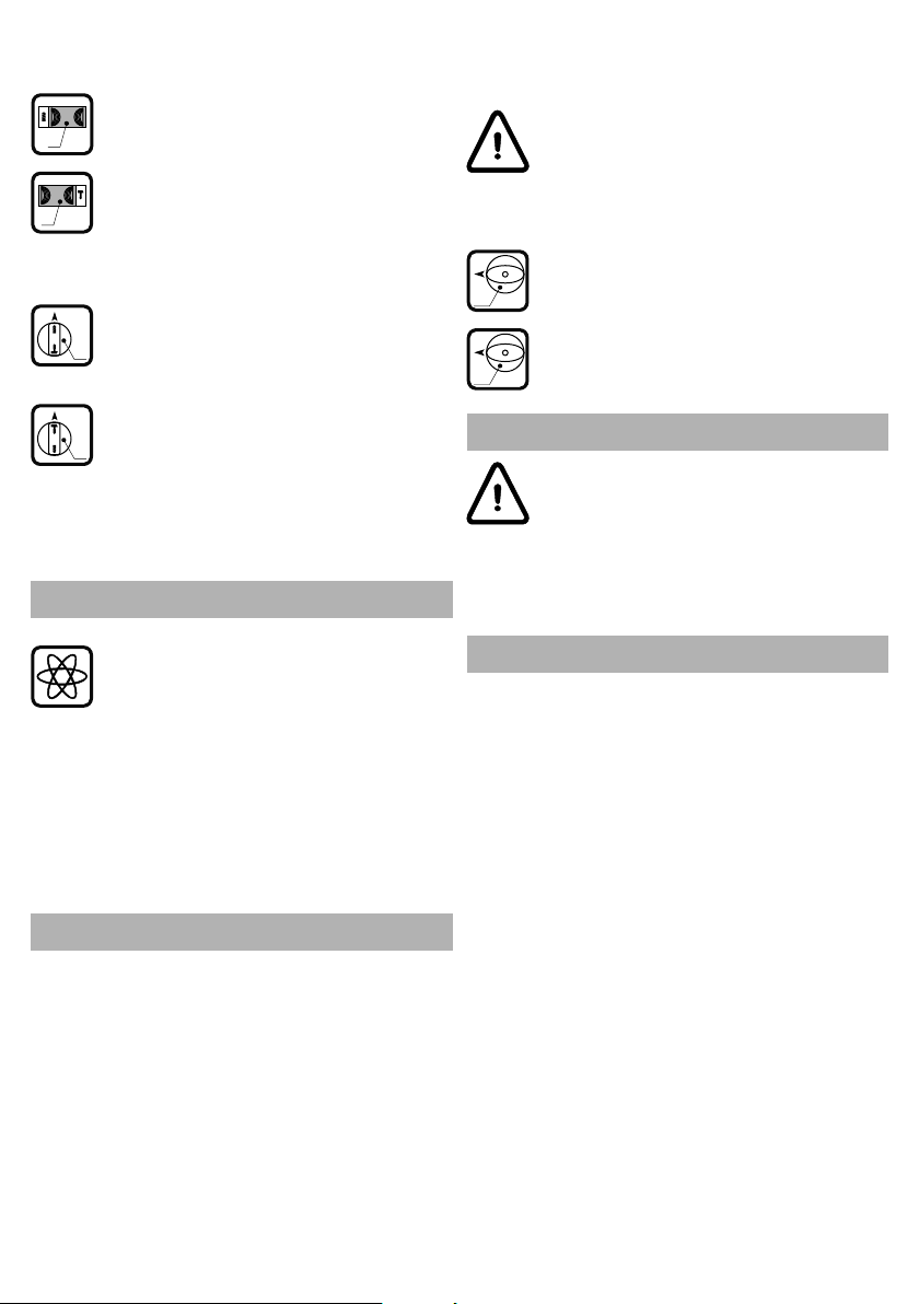
Ein- / Ausschalten
Schlagbohren:
Zum Umschalten in diesen Betriebsmodus
den Schalter 6 so drehen, dass das Zeichen
6
für Schlagbohrbetrieb mit der Markierung auf
dem Gehäuse übereinstimmt.
Sie können die Betriebsart bei laufendem
Elektrowerkzeug wechseln; es genügt, den Druck
auf das Werkzeug etwas zu vermindern.
Kurzes Ein- und Ausschalten
Zum Anschalten den Ein- / Ausschalter 10 drücken und
gedrückt halten, und zum Ausschalten wieder
loslassen.
Dauerhaftes Ein- / Ausschalten
Einschalten:
Ein- / Ausschalter 10 drücken und mit der Arretierung für
den Ein- / Ausschalter
Ausschalten:
Ein- / Ausschalter 10 drücken und loslassen.
11 feststellen.
Wechseln zwischen den
Betriebsmodi
Schalter 6 dient zum Umschalten zwischen den
folgenden Betriebsarten des Elektrowerkzeuges:
Bohren, Schrauben eindrehen, Schrauben
herausdrehen - Bohren in Holz, Plastikmaterial, Metall,
ohne Schlagfunktion. Einschrauben und Lösen von
Befestigungselementen;
Schlagbohren - Schlagbohren in Mauerwerk, Beton,
Naturstein.
[SBM-500 VS, SBM-600 VS, SBM-750 VS, SBM-750 V,
SBM-810 VS, SBM-810 V]
B o h r e n, S c h r au ben e in dreh e n ,
Schrauben herausdrehen:
Zum Umschalten in diesen Betriebsmodus
6
den Schalter 6 bis zum Anschlag nach rechts
schieben.
Schlagbohren:
Zum Umschalten in diesen Betriebsmodus
6
[SBM-810 VT, SBM-1050 VS, SBM-1050 VT, SBM-1050 DT]
den Schalter 6 bis zum Anschlag nach links
schieben.
B o h r e n, S c h r au ben e in dreh e n ,
Schrauben herausdrehen:
Zum Umschalten in diesen Betriebsmodus
den Schalter 6 so drehen, dass das Zeichen
6
für Bohrbetrieb mit der Markierung auf dem
Gehäuse übereinstimmt.
Deutsch
Stufenlose
Geschwindigkeitsregelung
Zur Regelung der Geschwindigkeit von 0 auf
Max. betätigen Sie die Taste 10. Ein leichter
Druck stellt eine niedrige Drehzahl ein, und
ermöglicht ein sanftes Anlaufen d er
Die stufenlose Geschwindigkeitsregelung bietet
folgende Vorteile:
langsamer Drehzahl auf glatten Flächen, z. B.
Keramikfliesen;
Verhindern das Verlaufen der Bohrerspitze beim
Zentrieren;
Verhindert eine Beschädigung des Bohrlochrandes
beim Herausziehen des Bohrers.
Maschine.
Möglichkeit zur Zentrierung der Bohrerspitze bei
Drehzahlschalter
Der Drehzahlschalter 9 dient zur Auswahl der
gewünschten Dreh- und Schlagzahl.
Ein- / Ausschalter 10 drücken und mit der Arretierung
für den Ein- / Ausschalter 11 feststellen.
Gewünschte Geschwindigkeit einstellen.
Die erforderliche Drehzahl ist vom Werkstoff abhängig
und kann durch praktischen Versuch ermittelt werden.
Nach längerem Arbeiten mit kleiner Drehzahl die
Maschine zur Abkühlung ca. 3 Minuten lang mit
maximaler Drehzahl im Leerlauf drehen lassen.
Drehzahlstufenschalter
[SBM-850 VT, SBM-1050 VT, SBM-1050 DT]
A c htung: Z u r V e r ä n d e r u n g d e r
eingestellten Drehzahl muss der Motor
völlig still stehen.
Der Drehzahlstufenschalter 13 dient zum Einstellen der
Drehzahl.
Erste Drehzahl - die Drehzahlwerte sind der
2
1
13
13
12
Tabelle mit den technischen Daten zu
entnehmen.
Zweite Drehzahl - die Drehzahlwerte sind
1
2
der Tabelle mit den technischen Daten zu
entnehmen.

Umschalten der Drehrichtung
Achtung: Vor der Umschaltung in
Linkslauf erst den Motor völlig zum
Stillstand kommen lassen.
Rechtslauf:
Den Umschalter 9 nach rechts schieben.
Linkslauf:
Den Umschalter 9 nach links schieben.
Arbeitshinweise
Die Gebrauchsanweisung für den Ständer 31 enthält
Hinweise für die korrekte Anwendung und den
Arbeitsablauf.
Rühren von verschiedenen Stoffen
[BM-1050 DL]
Entzündliche Stoffe (z. B. hoch brennbare
Lösungsmittel) und Materialien mit einer
Zündtemperatur von weniger als 21 °C
dürfen nicht verarbeitet werden. Lesen
Sie das Sicherheitsdatenblatt des Herstellers und
halten Sie sich an die Anweisungen.
Bohren
Beim Bohren in Metall ist es ratsam, etwas
Schmiermittel auf das Werkstück aufzutragen. Für
größere Löcher zuerst ein kleineres Loch vorbohren
und danach das Loch auf den gewünschten
Durchmesser aufbohren (siehe Abb. 11). Das Modell
BM-1050 DL bietet Ihnen aufgrund seiner speziellen
Konstruktion maximale Leistung beim Bohren in Stahl.
Beim Bohren in Holz ein zweites Brett auf der
Sichtseite festklemmen, um ein Ausbrechen des
Bohrlochs zu vermeiden (siehe Abb. 11). Vermindern
Sie vor Beendigung des Bohrens die Drehzahl, indem
Sie weniger stark auf den Ein / Aus-Schalter 10 drücken.
Damit vermindern Sie die Gefahr, dass das Bohrloch
aussplittert.
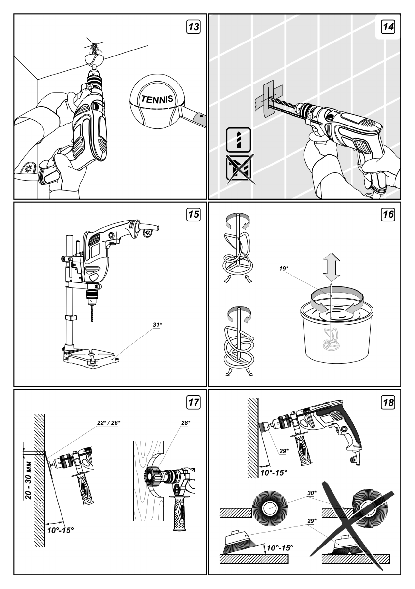
Wenden Sie beim Bohren in Wänden und Decken die
in den Abbildungen 12 und 13 gezeigten Maßnahmen
an, um den anfallenden Staub aufzufangen und die
Arbeitsbedingungen zu verbessern.
Beim Bohren in glasierte Keramikfliesen zuerst ein
Stück Klebeband auf der Fliese befestigen (über das
gepla nte Bohrl och), u m ein Ve rlauf en de s
Bohrwerkzeugs auf der glatten Fliese zu vermeiden und
zu verhindern, dass die glasierte Oberfläche springt
(siehe Abb. 14). Beginnen Sie mit niedriger Drehzahl
und erhöhen Sie die Drehzahl in dem Maße, wie Sie
tiefer in das Loch bohren. Achtung: Beim Bohren in
Keramikfliesen die Schlagfunktion ausschalten.
Schlagbohren
Das Schlagbohren ist unabhängig von der Druckkraft,
die Sie für diese Arbeit aufwenden; die Schlagwirkung
r es u l t i e r t e i n zi g u nd a l le i n a u s d e m
Schlagmechanismus Ihres Werkzeugs. Wenden Sie
deshalb keinen übermäßigen Druck an, andernfalls
kann der Bohrer blockieren oder der Motor wird
überlastet.
Bohren im stationärem Modus
Der Ständer 31 dient dazu, das Elektrowerkzeug
stationär zu betreiben (siehe Abbildung 15). Der
Ständer 31 erhöht die Bohrgenauigkeit und verbessert
gleichzeitig die Sicherheit beim Arbeiten.
Deutsch
Die Auswahl des Rührflügels 19 richtet sich nach der
Art des Materials, das gerührt werden soll. Für niedrig
viskose Flüssigkeiten wie z. B. Farbedispersionen,
Dichtstoffe, flüssigen Zement eignen sich Rührflügel mit
Blattdrehung nach links. Für hoch viskose Flüssigkeiten
wie z. B. gebrauchsfertige Gipsmasse, Beton, Kitt,
Polymerharze eignen sich Rührflügel mit Blattdrehung
nach rechts (siehe Abbildung 16).
Arbeiten Sie immer mit dem Drehgriff 4, er erleichtert
Ihnen die Arbeit und ermöglicht eine bessere Kontrolle
über das Elektrowerkzeug.
Der Behälter, in dem die Flüssigkeit gemischt wird,
muss sicher befestigt werden.
Bewegen Sie das Elektrowerkzeug auf und ab und in
kreisenden Bewegungen, um die gesamte Menge
optimal zu durchmischen.
Nach Abschluss der Arbeiten den Rührflügel 19
abwaschen und trocknen.
Schleifen
Schleifen mit Gummi-Poliertellern
Diese Poliermethode dient zum Polieren von
verschiedenen Oberflächenformen oder -profilen. Mit
Polierpads unterschiedlicher Körnungen können Sie die
gewünschte Oberflächenrauigkeit herstellen.
Gummi-Polierteller 22 oder 26 wie oben beschrieben
befestigen.
Elektrowerkzeug starten und auf maximale Drehzahl
kommen lassen, danach das Polierpad 22 oder 26
vorsichtig an die zu bearbeitende Oberfläche
heranführen.
Es wird empfohlen, das Elektrowerkzeug in einem
Winkel von 10° bis 15° zur bearbeiteten Oberfläche
anzustellen (siehe Abbildung 17). Bei einem geringeren
Anstellwinkel ist das Elektrowerkzeug schwieriger zu
führen. Bei einem größeren Anstellwinkel wird die
Be arbei tu ng sc hwierig er, un d es e ntstehe n
Vertiefungen in der Oberfläche.
Führen Sie das Elektrowerkzeug mit sanftem Druck
kreuz und quer über die Oberfläche. Übermäßiger
Druck bringt keine besseren Ergebnisse, sondern
ü b er l a st e t n u r d en M ot o r . R o t ier e nd e
Polierbewegungen hinterlassen auf der Oberfläche
spiralförmige Spuren.
13

Es ist wichtig, dass Sie das Elektrowerkzeug Versuchen Sie nicht, mit der Seitenfläche der Bürste
and au ern d bew ege n, a nde rn fal ls e nts te hen
Vertiefungen.
Beim Bearbeiten von Holz beginnen Sie mit einem
groben Schleifpad und wechseln dann zu einer feineren
Körnung. Auf diese Weise arbeiten Sie schneller und
erhalten eine bessere Oberfläche.
Metallformteilen (Rohrleitungen, Karosserieteile
usw.) müssen vor der Bearbeitung mit einem nicht
entzündlichen Mittel von entfettet werden.
Schleifen mit Fächerschleifscheiben
Diese Schleifmethode ermöglicht die Bearbeitung von
gekrümmten Oberflächen, und sie ist im Vergleich zu
Gummi-Schleiftellern relative leise und erzeugt weniger
Wärme. Der Gebrauch von Fächerschleifscheiben mit
ver sch ied ene n K örn ung en ges tat tet Ihn en,
unterschiedliche Oberflächenrauigkeiten zu erzeugen,
und nebenbei haben Fächerschleifscheiben eine
deutlich höhere Standzeit als Schleifpads.
Fächerschleifscheibe 28 wie oben beschrieben
montieren.
Elektrowerkzeug starten und auf maximale Drehzahl
kommen lassen, danach die Fächerschleifscheibe 28
vorsichtig an die zu bearbeitende Oberfläche
heranführen.
Dabei das Elektrowerkzeug wie in Abbildung 17
gezeigt an das Werkstück halten.
D i e E m p f ehl u n gen z um A rbe i t en m it
Fächerschleifscheiben 28 entsprechen im Grunde
denen zum Arbeiten mit dem Gummi-Schleifteller 22
oder 26.
Gebrauch der Bürsten
Drahtbürsten dienen zum Entfernen von Rost,
Lackresten oder anderen Beschichtungen von
verschiedenen Oberflächen.
Drahtbürste 29 oder 30 wie oben beschrieben
montieren.
Elektrowerkzeug starten und auf maximale Drehzahl
kommen lassen, danach die Drahtbürste 29 oder 30
vorsichtig an die zu bearbeitende Oberfläche
heranführen.
Halten Sie das Elektrowerkzeug so, dass nur die
Spitzen der Drahtbürste die zu bearbeitende Oberfläche
berühren. Beim Arbeiten mit Drahtbürsten 29 sollte das
Elektrowerkzeug in einem Winkel von 10° bis 15° zur
bearbeiteten Oberfläche angestellt werden (siehe
Abbildung 18).
Führen Sie das Elektrowerkzeug mit mäßigem Druck
über die Oberfläche. Übermäßiger Druck führt nicht zu
besseren Ergebnissen, sondern überlastet nur den
Motor und vermindert die Standzeit der Bürste (siehe
Abbildung 18).
Vorsicht - beim Bearbeiten von Kanten und kleinen
Winkeln besteht die Gefahr, dass das Elektrowerkzeug
zurückschlägt.
zu arbeiten, andernfalls vermindert sich die Standzeit
der Bürste und die Oberfläche wird unzureichend
bearbeitet.
Wartung und Reinigung
Vor jeglichen Arbeiten am Elektrowerkzeug den
Netzstecker ziehen.
Austausch der Kohlebürsten
Verschlissene Kohlebürsten rechtzeitig ersetzen. Ein
Anzeichen für verschlissene Kohlebürsten ist die
vermehrte Funkenbildung am Rotor des Elektromotors.
Achtung: Neue Kohlebürsten erzeugen ebenfalls
vermehrt Sprühfunken, bis sie sich eingeschliffen
haben.
Das A ustau schen der K ohlen bürst en s ollte
ausschl ießli ch i n einem DWT F ac hze nt rum
vorgenommen werden.
Schmieren der Ritzel
Elektrowerkzeugritzel sollten bei jedem zweiten
Austausch der Kohlebürsten mit einem Spezialöl
geschmiert werden.
Das Abschmieren der Ritzel sollte ausschließlich in
einem DWT Fachzentrum vorgenommen werden.
Austausch der Lager
Bei jedem zweiten Austausch der Kohlebürsten sollten
die Lager des Elektrowerkzeugs ausgetauscht werden.
Bei intensivem Gebrauch oder wenn sehr abrasives
Material bearbeitet wird, verschleißen die Lager unter
Umständen früher, was durch ein zunehmend lauteres
Betriebsgeräusch angezeigt wird. In diesem Fall ist es
notwendig, die Lager auszutauschen, damit sie nicht
völlig beschädigt werden und u. U. andere Teile
ebenfalls in Mitleidenschaft gezogen werden.
Das Austauschen der Lager sollte ausschließlich in
einem DWT Fachzentrum vorgenommen werden.
Reinigung des Elektrowerkzeuges
Im Inneren des Elektrowerkzeuges kann sich nach
längerem Gebrauch zur Metallbearbeitung (Schleifen,
Bürsten) leitfähiger Staub ansammeln. Blasen Sie das
Elektrowerkzeug deshalb in regelmäßigen Abständen
mit Druckluft durch die Lüftungsschlitze 7 hindurch
sauber.
Für sicheres und korrektes Arbeiten halten Sie das
Werkzeug und die Lüftungsschlitze sauber.
Wenn trotz aller Sorgfalt bei der Herstellung und dem
Testen des Geräts ein Fehler auftritt, lassen Sie die
Reparatur von einem autorisierten Fachhändler von
DWT-Elektrowerkzeuge ausführen.
Deutsch
14

Garantie
Für DWT-Geräte leisten wir Garantie gemäss den
gesetzlichen/länderspezifischen Bestimmungen
(Nachweis durch Rechnung oder Lieferschein).
Die Garantie gilt nicht für Verbrauchsmaterialien
und Zubehör, die teilweise zum Lieferumfang
gehören.
Eine Garantieleistung wird nicht erbracht in Fällen
von:
normalem Verschleiß von Mechanismen und
Baugruppen mit begrenzter Lebensdauer;
War tu n g u n d Austa us c h v o n s c hnell
verschleißenden Kleinteilen (K ohlebür sten,
Zahnrädern);
Überlastungen oder zu extensiven Auslastungen, die:
gleichzeitiges Versagen eines oder mehrerer
funktionell mit dem System verbundener
Kleinteile und Baugruppen;
Verbrennungen, Verkohlungen, Schmelzen
un ter Ei nfluss von zu h oh er i nn erer
Temperatur der Kleinteile (Heizelemente,
Schalter, Leitungen, Gehäuse) zur Folge
haben;
mechanischer Beschädigung, Vorhandensein
von Fremdkörpern im Gerät;
gewerbliche Nutzung;
Nu tz un g zu Z we ck en , die ni cht i n der
Bedienungsanleitung angegeben sind;
Demontagen und Reparaturen, die nicht von
Spezialisten der DWT vorgenommen wurden.
Änderungen vorbehalten.
Deutsch
15
500
1050
035411
021070
SBM-1050 DT
1050
030508
020646
BM-1050 DL
9.00
0-900 /
0-2500
600
9.00
0-550
40000
14400 /
3-16
1/8"-5/8"
1,5-13
1/16"-33/64"
16
5/8"
3,40
60 / 40
2-23/64"/1-37/64"
40
13
33/64"
1-37/64"
7.50
20 / 16
25/32" / 5/8"
3,20
7.05
92,00
/ II / II
87,00
10,68
103,00
2,20
98,00
610
1050
030461
020462
SBM-1050 VT
1050
030454
020455
SBM-1050 VS
810
030430
020431
SBM-810 VT
810
030638
020639
SBM-810 V
810
030423
020424
SBM-810 VS
750
030621
020622
SBM-750 V
750
030409
020400
SBM-750 VS
600
030386
020387
SBM-600 VS
500
030379
020370
SBM-500 VS
9.00
0-2880
0-1200 /
600
9.00
0-1700
430
6.80
0-2800
0-1000 /
450
6.80
0-2500
450
6.80
0-2500
390
6.30
0-2800
390
6.30
0-2800
255
5.00
0-2800
210
5.00
0-2800
46080
19520 /
27200
44800
16000 /
40000
40000
44800
44800
44800
44800
1,5-13
1/16"-33/64"
1,5-13
1/16"-33/64"
1,5-13
1/16"-33/64"
2-13
1/16"-33/64"
1,5-13
1/16"-33/64"
2-13
1/16"-33/64"
1,5-13
1/16"-33/64"
1,5-13
1/16"-33/64"
1,5-13
1/16"-33/64"
13
40 / 30
33/64"
1-37/64" / 1-3/16"
30
13
33/64"
1-3/16"
13
40 / 30
33/64"
1-37/64" / 1-3/16"
40
13
33/64"
1-37/64"
40
13
33/64"
1-37/64"
30
13
33/64"
1-3/16"
13
30
33/64"
1-3/16"
30
13
33/64"
1-3/16"
30
13
33/64"
1-3/16"
6.83
3,10
20 / 16
25/32" / 5/8"
16
5/8"
6.61
3,00
2,80
6.17
20 / 16
25/32" / 5/8"
16
5/8"
2,50
5.51
16
5/8"
2,50
5.51
16
5/8"
5.07
2,30
16
5/8"
2,30
5.07
13
2,10
4.63
33/64"
13
2,10
4.63
33/64"
91,00
90,00
96,00
96,00
96,00
90,00
90,00
93,00
/ II / II / II / II / II / II / II / II / II
93,00
6,22
105,00
7,03
104,00
3,20
107,00
20,30
107,00
20,30
107,00
2,90
104,00
2,90
104,00
7,52
104,00
7,52
104,00
400
180
3.30
002000
001461
BM-400 VS
[W]
[W]
[127 V ~50/60 Hz]
[230 V ~50/60 Hz]
Power tool specification
Drill / Impact drill
Order code
Rated power
Power output
0-2700
[RPM]
[Amps]
Amperage
No-load speed
[BPM]
Impact drilling
Gear rim chuck
Percussion rate
0,8-10
1/16"-25/64"
[mm]
[inches]
Keyless chuck
Speed control
Chuck tightening range
Reverse
20
25/32"1025/64"
[mm]
[mm]
[mm]
[inches]
[inches]
[inches]
- concrete
- steel
- wood
Drilling output:
/ II
1,50
3.31
[kg]
[lbs]
Weight
76,00
[dB(A)]
Sound pressure
Safety class
2,30
90,00
2
[m/s ]
[dB(A)]
Acoustic power
Weighted vibration
English
16

Power tool components
1 Keyless chuck *
2 Gear rim chuck *
3 Depth stop *
4 Auxiliary handle *
5 Clamping screw *
6 "Impact / drill" switch
7 Ventilation slots
8 Rotational direction switch
9 Speed selector thumbwheel
10 On / off-switch
11 Locking button for on / off switch
12 Keyless chuck (with lock) *
13 Step speed selector switch
14 Drill chuck key *
15 Metal drill *
16 Concrete drill *
17 Wood drills *
18 Clutch *
19 Stirring paddle *
20 Screwdriver bit *
21 Magnetic holder *
22 Rubber sanding plate *
23 Sanding disc *
24 Washer *
25 Screw *
26 Rubber sanding plate (velcro-type) *
27 Sanding disc (velcro-type) *
28 Leaf sanding disc *
29 Cup wire brush *
30 Circular wire brush *
31 Stand for stationary mounting of the electric drill *
32 Cap *
33 Screw *
* Optional extra
Not all of the accessories illustrated or described
are included as standard delivery.
Congratulations!
Dear Customer,
DWT is confident of the quality of its products and offers
an outstanding guarantee. Our aim is to provide quality
power tools at an affordable price. We hope that you will
enjoy using this power tool for many years. You may find
additional information on our electric tools, as well as on
our services on our web sites: www.dwtsys.de and
www.servicedwt.com.
The DWT team.
Intended use
Electric drills or impact electric drills are used for drilling
in steel, wood and ceramics. The ability to adjust the
speed and availability of the reverse mode allows the
power tool to be used as a screwdriver.
English
The area of the tool application can be expanded due to
use of additional accessories.
There is a possibility of a stationary installation of the
tool by use of some special accessories.
[SBM-500 VS, SBM-600 VS, SBM-750 VS, SBM-750 V,
SBM-810 VS, SBM-810 V, SBM-810 VT, SBM-1050 VS,
SBM-1050 VT, SBM-1050 DT]
The listed power tool models allow impact drilling in
bricks, concrete and similar materials to be
implemented.
[BM-1050 DL]
This power tool model is also purposed for stirring
powder construction materials such as lime, cement,
plastering mixtures, as well as for paints, lacquers and
similar materials containing no solvent.
Optional extra
You can find the recommended DWT accessories on
the page 150-156 of the instruction. The bright range of
the accessories will allow you to perform necessary
kinds of works effectively.
Safety instructions when operating
impact electric drill
Avoid electric tool motor stop, when loaded.
Maintain a stable position while working, hold your
electric tool with both hands.
Removing chips with the power tool engine running is
strictly forbidden.
Before starting work, make sure where hidden
electric cables and water and gas pipes are situated.
Damaging the electric supply wiring or engineering
communications may cause a severe harm to the
operator's life and health.
If the working schedule cannot exclude damaging the
main supply cables, they have to be de-energized.
During operation watch the position of a power cable
(it should always be positioned behind the tool). Do not
allow it to whip around your legs or arms.
Use only sharp drills without defects - it will make
working with the power tool easier.
The modification of the drills design and the use of
removable orifices and accessories not envisaged for
this power tool is strictly forbidden.
Do not apply excessive pressure when operating the
power tool - it can jam the drill and overload the engine.
Do not allow drills to jam in the material processed. If
this occurs, do not try to release them by means of the
power tool engine. This can put the power tool out of
order.
Striking out drills jammed in the material processed
with a hammer or other objects is strictly forbidden metal fragments can hurt both the operator and the
people nearby.
17

Avoid overheating your electric tool, when using it for Lock keyless chuck 1 or 12 on the power tool spindle,
a long time.
Mounting and adjustment of the
impact electric drill components
Before carrying out any works on the power tool it
must be disconnected from the mains.
having tightened screw 33. Attention: screw 33 has a
left-hand thread. Prior to that, move the cams of
keyless chuck 1 or 12 apart at the distance allowing
screw 33 to be tightened. To do that, rotate the front part
of keyless chuck 1 or 12 counter-clockwise with your
hand.
When keyless chuck 1 or 12 is being dismounted,
repeat the aforementioned operations in reverse order.
Wh en implementing the mounting
operations, do not apply excessive force
during the tightening fastening of
components in order not to damage the
threaded connections.
Auxiliary handle
[SBM-500 VS, SBM-600 VS, SBM-750 VS, SBM-750 V,
SBM-810 VS, SBM-810 V, SBM-810 VT, SBM-1050 VS,
SBM-1050 VT, BM-1050 DL, SBM-1050 DT]
When operating your tool hold additional handle 4 - it
improves the operation performance comfort and the
electric tool control.
Additional handle 4 may be positioned as deemed
comfortable by the user.
[SBM-500 VS, SBM-600 VS, SBM-750 VS, SBM-750 V,
SBM-810 VS, SBM-810 V, SBM-810 VT, SBM-1050 VS,
SBM-1050 VT, SBM-1050 DT]
Loose additional handle 4 as shown in fig. 1.
Place additional handle 4 in desired position.
Tighten additional handle 4 as shown in fig. 1.
[BM-1050 DL]
Release additional handle 4 as shown on picture 2.
Extract cork 32 and screw additional handle 4 into the
threaded opening.
Insert cork 32 into the freed threaded opening.
Depth stop
[SBM-500 VS, SBM-600 VS, SBM-750 VS, SBM-750 V,
SBM-810 VS, SBM-810 V, SBM-810 VT, SBM-1050 VS,
SBM-1050 VT, SBM-1050 DT]
Use depth limiter 3 to set a required drilling depth (see fig. 3).
Slacken clamp 5.
Move depth limiter 3 to set a required drilling depth.
Tighten clamp 5.
Mounting / dismounting of the keyless chuck
[BM-400 VS, SBM-750 V, SBM-810 V]
Screw keyless chuck 1 or 12 onto the power tool
spindle (see picture 4).
English
Mounting / dismounting of the gear rim chuck
[SBM-500 VS, SBM-600 VS, SBM-750 VS, SBM-810 VS,
SBM-810 VT, SBM-1050 VS, SBM-1050 VT, BM-1050 DL,
SBM-1050 DT]
Screw gear rim chuck 2 onto the power tool spindle
(see picture 4).
Lock gear rim chuck 2 on the power tool spindle,
having tightened screw 33. Attention: screw 33 has
left-a hand thread. Prior to that move apart the cams of
gear rim chuck 2 at the distance allowing to tighten
screw 33 to be tightened. To do that, release the grip of
the cams with clamping wrench 14, then rotate the quill
of gear rim chuck 2 counter-clockwise with your hand.
When gear rim chuck 2 is being dismounted, repeat
the aforementioned operations in reverse order.
Mounting / replacement of accessories
It is necessary to wear gloves when
extracting the drill from the chuck
because the drill can become very hot due
mounting / replacing wire brushes is also
recommended.
[BM-400 VS]
This model is equipped with keyless chuck 1. This
allows accessories to be mounted / replaced quickly and
without a key.
Move the cams of keyless chuck 1 apart at the
distance allowing an accessory to be mounted /
replaced. To do that, rotate the front part of keyless
chuck 1 counter-clockwise with your hand (see picture 5).
Mount / replace an accessory.
Rotate the front part of keyless chuck 1 clockwise with
your hand to lock the accessory mounted. Do not allow
the accessory to become distorted.
[SBM-750 V, SBM-810 V]
These models are equipped with keyless chuck (with
lock) . This allows accessories to be mounted /
replaced quickly and without a key and provides more
reliable locking of the accessory compared to an
ordinary keyless chuck.
18
to long operation. Wearing gloves when
12

Move the clutch in the back part of keyless chuck (with
lock) 12 back until it clicks into position (see picture 6).
Move the cams of keyless chuck (with lock) 12 apart
at the distance allowing an accessory to be mounted /
replaced. To do that, rotate the front part of keyless
chuck 12 counter-clockwise with your hand.
Mount / replace an accessory.
Rotate the front part of keyless chuck (with lock) 12
clockwise with your hand to lock the accessory
mounted. Do not allow the accessory to become
distorted.
To fix the lock, move the clutch in the back part of
keyless chuck (with lock) 12 forward until it clicks into
position.
[SBM-500 VS, SBM-600 VS, SBM-750 VS, SBM-810 VS,
SBM-810 VT, SBM-1050 VS, SBM-1050 VT, BM-1050 DL,
SBM-1050 DT]
Release the cams grip with clamping wrench 14, then
rotate the quill of gear rim chuck 2 counter-clockwise
with your hand (see picture 7) until the cams move apart
at the distance allowing an accessory to be mounted /
replaced.
Mount / replace an accessory.
Rotate the quill of gear rim chuck 2 clockwise with
your hand in order to lock the accessory mounted. Do
not allow the accessory to become distorted.
Tighten the cams of gear rim chuck 2 with clamping
wrench 14 applying a similar torque to each of the three
openings on the side surface of the chuck.
Screwdriver bit
When using the power tool as a screwdriver, use
magnetic holder 21 for reliable locking of screwdriver
bits 20 (see picture 8). A magnetic holder is not needed
for extended screwdriver bits 20 (specially purposed for
screwdrivers).
Mounting / dismounting the stirring paddle
[BM-1050 DL]
Dismount gear rim chuck 2, as described above.
With a horn wrench (not supplied with the power tool)
screw clutch 18 onto the power tool spindle (see picture 9).
Holding clutch 18 with a horn wrench (not supplied
with the power tool) screw stirring paddle 19 into it.
To dismount stirring paddle 19, repeat t he
aforementioned operations in reverse order.
Assembling the rubber sanding plate
Install washer 24 and sanding disc 23 onto screw 25
(see picture 10).
With a screwdriver (is not supplied with the power
tool), tighten screw 25 in the threaded opening of rubber
sanding plate 22.
Mount rubber sanding plate 22 as it is described
above.
English
Replacing the sanding disc
With a screwdriver (not supplied with the power tool),
release screw 25.
Remove worn out sanding disc 23.
Install washer 24 and new sanding disc 23 onto screw 25.
With a screwdriver (is not supplied with the power
tool), tighten screw 25 in the threaded opening of rubber
sanding plate 22.
Assembling the rubber sanding plate (velcro-type)
Press sanding disc (velcro-type) 27 tightly to the
surface of rubber sanding plate (velcro-type) 26, having
previously joined their edges (see picture 10).
Mount rubber sanding plate (velcro-type) 26 as
described above.
Replacing the sanding disc (velcro-type)
Hock the edge of worn out sanding disc (velcro-type) 27
and remove it by pulling it by the edges.
Press new sanding disc (velcro-type) 27 tightly to the
surface of the rubber sanding plate (velcro-type) 26,
having previously joined their edges.
Initial operating
Always use the correct supply voltage: the power supply
voltage must match the information quoted on the tool
identification plate.
Switching On / Off
Short-term switching on / off
To switch on, press and hold on / off switch 10, to switch
off - release it.
Long-term switching on / off
Switching on:
Push on / off switch 10 and lock it in the position with
locking button for on / off switch 11.
Switching off:
Push and release on / off switch 10.
Switching between operation modes
Switch 6 is purposed for switching between the following
operation modes of the power tool:
drilling, screwing, unscrewing - drilling without
impact in wood, synthetic materials, metal. Screwing
and unscrewing fastening components;
impact drilling - impact drilling in brick, concrete,
natural stone.
19
[SBM-500 VS, SBM-600 VS, SBM-750 VS, SBM-750 V, Step speed selector switch
SBM-810 VS, SBM-810 V]
Drilling, screwing, unscrewing:
To switch to this operation mode, move switch 6
6
right to the stop.
Impact drilling:
6
To switch to this operation mode, move switch 6
left to the stop.
[SBM-850 VT, SBM-1050 VT, SBM-1050 DT]
Attention: one can only change the
revolutions per minute range after the
engine fully stops.
Step speed selector switch 13 allows the range of
changing revolutions per minute to be set.
[SBM-810 VT, SBM-1050 VS, SBM-1050 VT, SBM-1050 DT]
Drilling, screwing, unscrewing:
To switch to this operation mode, turn switch 6
so that the drilling sign coincides with the
6
mark on the body.
Impact drilling:
To switch to this operation mode, turn switch 6
so that the Impact drilling sign coincides with
6
the mark on the body.
One can switch to another operation mode without
stopping the power tool, simply decrease pressure
applied to it to some extent.
Stepless speed adjustment
Speed is controlled from 0 to maximum by
pressing force of button 10. Weak pressing
results in low revolutions, which enable a
A stepless speed adjustment also provides the following
advantages:
availability to center the drill at low rotation speed, for
example, on smooth surfaces (glazed ceramic tiles,
etc.);
preventing drill sliding during the centering;
preventing opening mouth destruction during the
extraction of the drill.
smooth power tool switch-on.
Speed selector switch
The required number of revolutions per minute as well
as the required number of impacts is set with speed
selector switch 9.
Push on / off switch 10 and lock it in the position with
locking button for on / off switch 11.
Set the needed speed.
The required speed is dependent on the material and
can be determined with practical trials.
After longer periods of working at low speed, allow the
machine to cool by running for approx. 3 minutes at
maximum speed with no load.
English
The first speed - you can find the values of
2
1
13
13
the revolutions per minute range in the
technical specifications table.
The second speed - you can find the values
1
2
of the revolutions per minute range in the
technical specifications table.
Changing the rotational directions
Caution: switch on the reverse gear after
the motor runs to a standstill, only.
Clockwise rotation:
Move reverse switch 9 to the right.
Anticlockwise rotation:
Move reverse switch 9 to the left.
Operating instruction
Drilling
It is advisable to lubricate your drilling piece from time
to time when drilling holes in metals. When drilling wider
holes, it is desirable to drill first a narrow hole then drill up
it to the required diameter (see fig. 11). You can gain
maximum performance when drilling in steel by using
BM-1050 DL model, as this is caused due to
peculiarities in its design.
When drilling holes in wood, to avoid drill exit cracking
apply to the expected exit site a piece of board with
special attachments so that the surfaces tightly stick
together (see fig. 11). Before finishing drilling decrease
the number of revolutions per minute (having decreased
the pressure on on / off switch 10). This will also
decrease the splitting of the billet surface.
In order to decrease dust formation and make the
implementation of works more convenient during drilling
holes in walls and ceilings, take measures shown on
pictures 12 and 13.
When drilling holes in glazed ceramic tiles, in order to
improve the drill centering accuracy and to save the
glaze from damage, apply adhesive tape to the
presumed hole center and drill after that (see fig. 14).
Start drilling at lower speed increasing it as the hole
deepens. Caution: drill tiles in the impactless drilling
operation mode only
20
.

Impact drilling
During the impact drilling, the result does not depend on
the pressure applied to the power tool - this is caused
due to the peculiarities in the impact mechanism design.
That is why you should not apply excessive pressure to
the power tool - it can jam the drill and overload the
engine.
Drilling in stationary mode
Stand 31 creates the possibility for the stationary
mounting of the power tool (see picture 15). The
application of stand 31 increases the accuracy of drilling
and provides greater safety during the implementation
of works.
One can find rec omm end ati ons on mounting
operations, the correct usage and order of works in the
instructions for stand 31.
Stirring various substances
[BM-1050 DL]
Do not process explosive substances (for
example, highly inflammable solvents)
and materials with ignition temperature of
lower than 21°С. Study the manufacturer's
instructions for such kind of materials carefully and
stick to them.
The selection of stirring paddle 19 type depends on
the type of substances stirred. Use stirring paddles with
left-hand blade spinning for low-viscosity substances
(dispersed paints, lacquers, sealing compounds, liquid
cement solution). Use stirring paddles with right-hand
blade spinning for high-viscosity substances (readymade plastering solution, concrete, putty, polymeric
resins) (see picture 16).
Always use additional handle 4, as it makes the
implementation of works more convenient and
increases the degree of control over the power tool.
Fix the container with the mixture stirred carefully
during the work.
Move the power tool upward, downward and in
circular movements to stir the mixture in the best
manner in its whole volume.
After finishing the works, wash and wipe stirring
paddle 19.
Sanding
Sanding with the rubber sanding plate
Sanding with this method allows surfaces of various
forms and profiles to be processed, and the application
of sanding discs with various grits allows surfaces with
various roughness to be achieved.
Install rubber sanding plate 22 or 26 as described
above.
English
Start the power tool, wait until the engine gains its
maximum speed and only after that smoothly bring
rubber sanding plate 22 or 26 to the surface processed.
Holding the power tool at an angle of 10° to 15°
relating to the surface processed (see picture 17) is
recommended. If this angle is less than recommended,
it will make controlling the power tool more difficult. If this
angle is more than recommended, the processing
quality will decrease and hollows will be left on the billet
surface.
Make crossing movements by applying moderate
pressure to the power tool. Excessive pressure will not
bring better results but it will overload the engine.
Sanding with circular movements will leave spiral traces
on the surface processed.
Do not detain the power tool in one place - it will lead
to the formation of a hollow.
When processing wooden surfaces start with sanding
with sanding discs of a coarser grit and finish with
sanding discs of a finer grit. It will speed up the
implementation of works and allow a smoother surface
to be achieved.
Prior to processing profile metallic surfaces (tubes,
automobile body parts, etc.), remove any remnants of oil
from them with incombustible chemicals.
Sanding with leaf sanding disc
Sanding with this method allows profile curved surfaces
to be processed and this is characterized with lesser
noise and heating compared to sanding with the rubber
sanding plate. The application of leaf sanding discs with
various grits allows surfaces with various roughness to
be achieved, and the operation life of leaf sanding discs
is much longer than that of sanding discs.
Install leaf sanding disc 28 as described above.
Switch on the power tool, wait until the engine gains
its maximum speed and only after that smoothly bring
leaf sanding disc 28 to the billet surface.
Holding the power tool concerning the surface
processed as shown on picture 17 is recommended.
Recommendations concerning the implementation of
works with leaf sanding disc 28 are similar to those as
when sanding with rubber sanding plate 22 or 26.
Operating the wire brushes
Wire brushes allow rust, paint-and-lacquer materials
and other coatings from various surfaces to be
removed.
Install wire brush 29 or 30 as described above.
Start the power tool, wait until the engine gains its
maximum speed and only after that smoothly bring wire
brush 29 or 30 to the surface processed.
Holding the power tool concerning the surface
processed in such a way so that only the ends of the
brush wire contact th e surface processed is
recommended. When operating cup wire brush 29, hold
the power tool at an angle of 10° to 15° relating to the
surface processed (see picture 18).
21

Move the power tool by applying slight pressure to it.
Excessive pressure will not bring better results but it will
overload the engine and decrease the operation life of
the brush significantly (see picture 18).
Beware of recoil when processing edges and sharp
angles.
Do not work with the side surface of the brush wire, as
it will decrease its operation life significantly and bring
worse results of the works.
Maintenance and cleaning
Before carrying out any works on the power tool it
must be disconnected from the mains.
Replacing the carbon brushes
Replace the worn carbon brushes opportunely. The sign
of the wearing out of carbon brushes is an increase of
ring sparklings on the collector of the electric engine
rotor. Attention: increased ring sparkling is also
observed after the installation of new carbon
brushes before they fit.
Carbon brushes should be replaced only at specialized
DWT service centres.
Lubrication of the pinions
Power tool pinions should be lubricated with a special oil
during every second replacement of carbon brushes.
Power tool pinions should be lubricated only at
specialized DWT service centers.
Replacing the bearings
During every second replacement of carbon brushes,
replace the power tool bearings. During intensive
operation and in case of processing abrasive materials,
bearings can wear out prematurely, the sign of which is
increased noise during the operation of the power tool.
In this case, it is also necessary to replace the bearings
so as not to allow their destruction and possible putting
other parts out of operation.
Bearings should be replaced only at specialized DWT
service centers.
Cleaning of the power tool
During the long treatment of metal (sanding, wire
brushes operation), current-conducting dust can be
accumulated inside the power tool. Blow the power tool
with compressed air regularly through ventilation slots 7.
For safe and proper working, always keep the power
tool and the ventilation slots clean.
If the power tool should fail despite the rigorous
manufacturing and testing procedures, repair should be
carried out by an authorized customer services centre
for DWT power tools.
Warranty
We guarantee that DWT appliances are in
accordance w ith statutory/cou ntry-specif ic
regulations (proof of purchase by invoice or
delivery note).
The warranty is not valid for consumables and
accessories which partly belong to the scope of
supplies.
The warranty cannot be invoked in the following
cases:
normal wear of mechanisms and assemblies
which have a limited life;
maintenance and replacement of hardware that
wears quickly (carbon brushes, gearwheels);
overloads or loads which are too extensive and
lead to:
simultaneous failure of one or more
hardware parts and assemblies functionally
connected with the system;
burning, charring, melting due to excessive
internal temperatures of the hardware (heating
elements, switches, wiring, housings);
mechanical damage, presence of foreign objects
in the appliance;
commercial use;
use for purposes not mentioned in the operating
instructions;
dismantling and repair work not carried out by
DWT specialists.
The manufacturer reserves the possibility to introduce changes.
English
22

500
1050
035411
021070
SBM-1050 DT
1050
030508
020646
BM-1050 DL
9.00
0-900 /
0-2500
600
9.00
0-550
40000
14400 /
3-16
1/8"-5/8"
1,5-13
1/16"-33/64"
16
5/8"
3,40
60 / 40
2-23/64"/1-37/64"
40
13
33/64"
1-37/64"
7.50
20 / 16
25/32" / 5/8"
3,20
7.05
92,00
/ II / II
87,00
10,68
103,00
2,20
98,00
610
1050
030461
020462
SBM-1050 VT
1050
030454
020455
SBM-1050 VS
810
030430
020431
SBM-810 VT
810
030638
020639
SBM-810 V
810
030423
020424
SBM-810 VS
750
030621
020622
SBM-750 V
750
030409
020400
SBM-750 VS
600
030386
020387
SBM-600 VS
500
030379
020370
SBM-500 VS
9.00
0-2880
0-1200 /
600
9.00
0-1700
430
6.80
0-2800
0-1000 /
450
6.80
0-2500
450
6.80
0-2500
390
6.30
0-2800
390
6.30
0-2800
255
5.00
0-2800
210
5.00
0-2800
46080
19520 /
27200
44800
16000 /
40000
40000
44800
44800
44800
44800
1,5-13
1/16"-33/64"
1,5-13
1/16"-33/64"
1,5-13
1/16"-33/64"
2-13
1/16"-33/64"
1,5-13
1/16"-33/64"
2-13
1/16"-33/64"
1,5-13
1/16"-33/64"
1,5-13
1/16"-33/64"
1,5-13
1/16"-33/64"
13
40 / 30
33/64"
1-37/64" / 1-3/16"
30
13
33/64"
1-3/16"
13
40 / 30
33/64"
1-37/64" / 1-3/16"
40
13
33/64"
1-37/64"
40
13
33/64"
1-37/64"
30
13
33/64"
1-3/16"
13
30
33/64"
1-3/16"
30
13
33/64"
1-3/16"
30
13
33/64"
1-3/16"
6.83
3,10
20 / 16
25/32" / 5/8"
16
5/8"
6.61
3,00
2,80
6.17
20 / 16
25/32" / 5/8"
16
5/8"
2,50
5.51
16
5/8"
2,50
5.51
16
5/8"
5.07
2,30
16
5/8"
2,30
5.07
13
2,10
4.63
33/64"
13
2,10
4.63
33/64"
91,00
90,00
96,00
96,00
96,00
90,00
90,00
93,00
/ II / II / II / II / II / II / II / II / II
93,00
6,22
105,00
7,03
104,00
3,20
107,00
20,30
107,00
20,30
107,00
2,90
104,00
2,90
104,00
7,52
104,00
7,52
104,00
400
180
3.30
002000
001461
BM-400 VS
[W]
[W]
[127 V ~50/60 Hz]
[230 V ~50/60 Hz]
Spécifications de l'outil électrique
Code d'ordre
Perceuse / Perceuses à percussion
Puissance de sortie
Puissance absorbée
0-2700
-1
[А]
[min ]
Ampérage
Régime à vide
-1
[min ]
Perçage percutant
Fréquence percussion
Mandrin de perçage à couronne dentée
0,8-10
1/16"-25/64"
[mm]
[pouces]
Mandrin auto-serrant
Commande de vitesse
Plage de resserrement du
mandrin
Mécanisme de enversement
20
25/32"1025/64"
[mm]
[mm]
[mm]
[pouces]
[pouces]
[pouces]
- bois
- béton
- acier
Puissance de perçage:
/ II
1,50
3.31
[kg]
[lbs]
Poids
76,00
[dB(A)]
Pression acoustique
Classe de protection
2,30
90,00
2
[m/s ]
[dB(A)]
Puissance acoustique
Vibration
Français
23

Composants de l'outil électrique
1 Mandrin auto-serrant *
2 Mandrin de perçage à couronne dentée *
3 Butée de profondeur *
4 Poignée supplémentaire *
5 Vis de serrage *
6 Sélecteur "percussion / perceuse"
7 Fentes d'aération
8 Inverseur de sens de marche
9 Molette de sélection de vitesse
10 Sélecteur marche / arrêt
11 Bouton de blocage de l'interrupteur marche / arrêt
12 Mandrin auto-serrant (avec verrou) *
13 Sélecteur de vitesse étape par étape
14 Clé pour le mandrin de perçage *
15 Mèche métallique *
16 Mèche à béton *
17 Mèche à bois *
18 Embrayage *
19 Agitateur *
20 Embout de tournevis *
21 Aimant de retenue *
22 Plaque abrasive en caoutchouc *
23 Disque abrasif *
24 Rondelle *
25 Vis *
26 Plaque abrasive en caoutchouc (type velcro) *
27 Disque abrasif (type velcro) *
28 Disque abrasif *
29 Brosse métallique coupe *
30 Brosse métallique circulaire *
31 Socle pour montage fixe de la perceuse électrique *
32 Bouchon *
33 Vis *
* Accessoires
Une partie des accessoires représentés et décrits
ne figurent pas dans la livraison.
Felicitations!
Cher client,
DWT fait confiance à la qualité de ses produits et offre
une garantie exceptionnelle. Notre but est de fournir des
outils électriques de qualité à un prix abordable. Nous
espérons que vous profiterez de l'utilisation de cet outil
électrique pendant de nombreuses années. Vous
pourrez trouver des informations supplémentaires sur
nos outils électriques et nos services sur nos sites
Internet: www.dwtsys.de et www.servicedwt.com.
DWT, toujours à votre service.
Utilisation normale
Les perceuses électriques ou les perceuses électriques
à percussion sont utilisées pour percer dans l'acier, le
bois et la céramique. Le réglage de la vitesse et la
fonction marche arrière permettent d'utiliser l'outil
comme un tournevis.
Français
La portée d'utilisation de l'outil peut être élargie en
employant des accessoires supplémentaires.
Il est possible d'installer l'outil de façon fixe (grâce à des
accessoires spéciaux).
[SBM-500 VS, SBM-600 VS, SBM-750 VS, SBM-750 V,
SBM-810 VS, SBM-810 V, SBM-810 VT, SBM-1050 VS,
SBM-1050 VT, SBM-1050 DT]
Les modèles d'outils électriques énumérés ci-dessus
permettent d'exécuter un perçage à percussion dans la
brique, le ciment et les matériaux similaires.
[BM-1050 DL]
Ce modèle d'outil électrique est aussi conçu pour le
mélange des matériaux de construction en poudre tels
que la chaux, le ciment, les mélanges de plâtre, ainsi
que les peintures, les laques et les matériaux similaires
ne contenant pas de solvant.
Accessoires
Vous pouve z tr ou ver le s acces so ir es DWT
reccomandés à la page 150-156 du manuel. La vaste
gamme d'accessoires vous permetra d'effectuer
chaque type de travail.
Instructions de sécurité pour
l'utilisation de la perceuse électrique
à percussion
Évitez d'arrêter le moteur d'un outil électrique lorsqu'il
est sous charge.
Gardez une position ferme en travaillant, tenez l'outil
électrique à deux mains.
Il est formellement déconseillé de retirer les éclats
lorsque le moteur de la perceuse est en marche.
Avant de commencer un travail, assurez-vous de
savoir où se trouvent les câbles électriques et les
conduites d'eau et de gaz c achés. Le fait
d'endommager le fil d'alimentation électrique ou la
construction mécanique peut entraîner des blessures
graves ou mettre la vie de l'opérateur en danger.
Si le programme de travail ne peut pas exclure le fait
d'endommager les câbles d'alimentation principaux,
ceux-ci doivent être mis hors tension.
Pendant l'opération, surveiller la position du câble
d'alimentation (qui doit toujours être placé derrière
l'outil). Ne pas le laisser s'enrouler autour de vos bras ou
de vos jambes.
N'utiliser que des mèches aiguisées et sans défauts,
cela facilitera le travail de l'outil électrique.
Il est formellement déconseillé de modifier la
conception des mèches et d'utiliser des orifices
amovibles et des accessoires non prévus pour cet outil
électrique.
Ne pas appliquer de pression excessive lors de
l'utilisation de l'outil électrique - cela pourrait bloquer la
perceuse et surcharger le moteur.
24

Ne pas laisser les mèches se bloquer dans le
matériau traité. Si cela se produit, ne pas essayer de les
libérer au moyen du moteur de l'outil. Cela risquerait de
l'endommager.
Il est formellement déconseillé de frapper sur des
mèches coincées dans le matériau traité avec un
marteau ou tout autre objet - les fragments en métal
pourraient blesser l'opérateur ou les personnes à
proximité.
Évitez de faire surchauffer votre outil électrique en
l'utilisant de façon prolongée.
Butée de profondeur
[SBM-500 VS, SBM-600 VS, SBM-750 VS, SBM-750 V,
SBM-810 VS, SBM-810 V, SBM-810 VT, SBM-1050 VS,
SBM-1050 VT, SBM-1050 DT]
Utilisez le limiteur de profondeur 3 pour établir la
profondeur de forage voulue (voir figure 3).
Desserrez l'attache 5.
Déplacez le limiteur de profondeur 3 jusqu'à la
profondeur de forage voulue.
Resserrez l'attache 5.
Montage et réglage des
composantes de la perceuse
électrique à percussion
Avant de commencer à travailler avec l'outil
électrique, s'assurer qu'il est débranché.
Lors des opérations de montage, ne pas
appliquer de force excessive pendant la
fixation des composantes afin de ne pas
endommager les filetages.
Poignée supplémentaire
[SBM-500 VS, SBM-600 VS, SBM-750 VS, SBM-750 V,
SBM-810 VS, SBM-810 V, SBM-810 VT, SBM-1050 VS,
SBM-1050 VT, BM-1050 DL, SBM-1050 DT]
Lorsque vous faites fonctionner votre outil, tenez la
poignée supplémentaire 4; elle améliore le confort de
performance d'opération et le contrôle de l'outil
électrique.
La poignée supplémentaire 4 peut être placée dans la
position la plus confortable pour l'utilisateur.
[SBM-500 VS, SBM-600 VS, SBM-750 VS, SBM-750 V,
SBM-810 VS, SBM-810 V, SBM-810 VT, SBM-1050 VS,
SBM-1050 VT, SBM-1050 DT]
Desserrez la poignée supplémentaire 4 comme
montré dans la figure 1.
Placez la poignée supplémentaire 4 dans la position
souhaitée.
Serrez la poignée supplémentaire 4 comme montré
dans la figure 1.
[BM-1050 DL]
Détacher la poignée auxiliaire 4 tel que montré dans
l'image 2.
Extraire le bouchon 32 et la vis de la poignée
auxiliaire 4 par l'ouverture filetée.
Insérer le bouchon 32 dans l'ouverture filetée libérée.
Français
Montage / démontage du mandrin auto-serrant
[BM-400 VS, SBM-750 V, SBM-810 V]
Visser le mandrin auto-serrant 1 ou 12 sur la broche
de l'outil (voir image 4).
Verrouiller le mandrin auto-serrant 1 ou 12 sur la
broche de l'outil après avoir resserré la vis 33.
Attention: la vis 33 est filetée à gauche. Avant cela,
écarter les cames du mandrin auto-serrant 1 ou 12 à
une distance permettant de serrer la vis 33. Pour ce
faire, faire tourner avec la main la partie avant du
mandrin auto-serrant 1 ou 12 dans le sens inverse des
aiguilles d'une montre.
Pour démonter le mandrin auto-serrant 1 ou 12,
répéter les opérations ci-dessus dans l'ordre inverse.
Monter / démonter le mandrin de couronne
[SBM-500 VS, SBM-600 VS, SBM-750 VS, SBM-810 VS,
SBM-810 VT, SBM-1050 VS, SBM-1050 VT, BM-1050 DL,
SBM-1050 DT]
Visser le mandrin de couronne 2 sur la broche de
l'outil électrique (voir image 4).
Verrouiller le mandrin de couronne 2 sur la broche de
l'outil électrique, après avoir serré la vis 33. Attention:
la vis 33 est filetée à gauche. Avant cela, écarter les
cames du mandrin de couronne 2 d'une distance
permettant de serrer la vis 33. Pour ce faire, libérer la
prise des cames à l'aide de la clé de serrage 14, puis
tourner à la main le fourreau du mandrin de couronne 2
dans le sens inverse des aiguilles d'une montre.
Pour démonter le mandrin de couronne 2, répéter les
opérations ci-dessus dans l'ordre inverse.
Monter / remplacer les accessoires
Il est nécessaire de porter des gants lors
de l'extraction de la mèche du mandrin car
la perceuse peut devenir très chaude si
elle a fonctionné longtemps. Le port de
gants lors du montage / remplacement des brosses
métalliques est également recommandé.
[BM-400 VS]
Ce modèle est équipé d'un mandrin auto-serrant 1. Cela
permet de monter / remplacer rapidement les
accessoires et sans une clé.
25

Déplacer les cames du mandrin auto-serrant 1 à une
distance permettant de monter / remplacer un
accessoire. Pour ce faire, tourner à la main la partie
avant du mandrin auto-serrant 1 dans le sens inverse
des aiguilles d'une montre (voir image 5).
Monter / remplacer un accessoire.
Tourner la partie avant du mandrin auto-serrant 1
dans le sens des aiguilles d'une montre avec la main
afin de verrouiller l'accessoire monté. Ne pas aller
jusqu'à tordre l'accessoire.
[SBM-750 V, SBM-810 V]
Ces modèles sont équipés d'un mandrin auto-serrant
(avec verrou) 12. Cela permet de monter / remplacer
rapidement les accessoires et sans clé et fournit une
fixation plus fiable de l'accessoire comparé aux
mandrins auto-serrant ordinaires.
Déplacer l'embrayage de la partie arrière du mandrin
auto-serrant (avec verrou) 12 vers l'arrière jusqu'à ce
qu'il produise un clic indiquant qu'il a atteint sa position
(voir image 6).
Ecarter les cames du mandrin auto-serrant (avec
verrou) 12 d'une distance permettant de monter /
remplacer un accessoire. Pour ce faire, tourner à la
main la partie avant du mandrin auto-serrant 12 dans le
sens inverse des aiguilles d'une montre.
Monter / remplacer un accessoire.
Faire tourner à la main la partie avant du mandrin
auto-serrant (avec verrou) 12 dans le sens des aiguilles
d'une montre pour verrouiller l'accessoire monté en
position. Ne pas aller jusqu'à tordre l'accessoire.
Pour fixer le verrou, déplacer l'embrayage de la partie
arrière du mandrin auto-serrant (avec verrou) vers
l'avant jusqu'à ce qu'il se produise un clic indiquant qu'il
a atteint sa position.
[SBM-500 VS, SBM-600 VS, SBM-750 VS, SBM-810 VS,
SBM-810 VT, SBM-1050 VS, SBM-1050 VT, BM-1050 DL,
SBM-1050 DT]
Libérer la prise des cames à l'aide de la clé de serrage 14,
tourner ensuite le fourreau du mandrin de couronne 2
dans le sens inverse des aiguilles d'une montre avec la
main (voir image 7) jusqu'à ce que les cames se soient
écartées d'une distance permettant de monter /
remplacer un accessoire.
Monter / remplacer un accessoire.
Tourner le fourreau du mandrin de couronne 2 dans le
sens des aiguilles d'une montre avec la main pour
verrouiller l'accessoire monté en position. Ne pas aller
jusqu'à tordre l'accessoire.
Serrer les cames du mandrin de couronne 2 à l'aide
de la clé de serrage 14 en appliquant un moment de
torsion similaire à chacune des trois ouvertures de la
surface de l'embrayage.
Embout de tournevis
Si l'outil électrique est utilisé comme tournevis, utiliser
l'aimant de retenue 21 pour un verrouillage sûr de
12
Français
l'embout de tournevis 20 (voir image 8). L'aimant de
retenue n'est pas nécessaire pour les embouts de
tournevis prolongés 20 (spécialement conçus pour les
tournevis).
Monter / démonter l'agitateur
[BM-1050 DL]
Démonter le mandrin de couronne 2, comme décrit ci-
dessus.
À l'aide d'une clé conique (non fournie avec l'outil
électrique) visser l'embrayage 18 sur la broche de l'outil
électrique (voir image 9).
Tout en maintenant l'embrayage 18 à l'aide d'une clé
conique (non fournie avec l'outil électrique) visser
l'agitateur 19 à l'intérieur.
Pour démonter l'agitateur 19, répéter les opérations
ci-dessus dans l'ordre inverse.
Montage de la plaque abrasive en caoutchouc
Installer la rondelle 24 et le disque abrasif 23 sur la vis 25
(voir image 10).
À l'aide d'un tournevis (non fourni avec l'outil
électrique), serrer la vis 25 dans l'ouverture filetée de la
plaque abrasive en caoutchouc 22.
Monter la plaque abrasive en caoutchouc 22 comme
décrit ci-dessus.
Remplacer le disque abrasif
À l'aide d'un tournevis (non fourni avec l'outil
électrique), défaire la vis 25.
Retirer le disque abrasif 23 usé.
Installer la rondelle 24 et le nouveau disque abrasif 23
sur la vis 25.
À l'aide d'un tournevis (non fourni avec l'outil
électrique), serrer la vis 25 dans l'ouverture filetée de la
plaque abrasive en caoutchouc 22.
Montage de la plaque abrasive en caoutchouc (type
velcro)
Appuyer fermement sur le disque abrasif (type velcro) 27
sur la surface de la plaque abrasive en caoutchouc (type
velcro) 26, après en avoir joint les bords (voir image 10).
Monter la plaque abrasive en caoutchouc (type
velcro) 26 comme décrit ci-dessus.
Remplacer le disque abrasif (type velcro)
Attraper le bord du disque abrasif usé (type velcro) 27
et l'enlever en le tirant par les bords.
Appuyer fermement sur le nouveau disque abrasif
(type velcro) 27 sur la surface de la plaque abrasive en
caoutchouc (type velcro) 26, après en avoir joint les
bords.
26

Mise en service Ajustage de vitesse continue
Vérifier la tension du secteur: la tension de la source de
courant (secteur) doit être identique à celle indiquée sur
la plaque signalétique de la machine.
Marche / Arrêt
Marche / arrêt à court terme
Pour mettre en marche, presser et maintenir le
sélecteur on / off 10, pour arrêter - le relâcher.
Marche / arrêt à long terme
Activer:
Pousser le sélecteur on / off 10 et le bloquer en position
à l'aide du bouton de blocage du sélecteur on / off 11.
Désactiver:
Pousser et relâcher le sélecteur on / off 10.
Changer de mode d'opération
Le sélecteur est conçu pour changer entre les modes
d'opération suivants:
percer, visser, dévisser - percer sans percussion
dans des matériaux en bois, synthétique ou en métal.
Vissage et dévissage des éléments de fixation;
percer à percussion - perçage à percussion dans la
brique, le béton et la pierre naturelle.
[SBM-500 VS, SBM-600 VS, SBM-750 VS, SBM-750 V,
SBM-810 VS, SBM-810 V]
6
La vitesse se contrôle de 0 au maximum par
pression sur le bouton 10. Appuyez
faiblement pour obtenir des révolutions
sans à-coup de l'appareil.
Le réglage de vitesse continue apporte aussi les
avantages suivants:
possibilité de centrer la perceuse à faible vitesse de
rotation, par exemple sur les surfaces lisses (carreaux
de céramique vernissés, etc.);
empêche la perceuse de glisser pendant le centrage;
empêche la destruction du col d'une ouverture
pendant l'extraction de la perceuse.
basses, ce qui permet une mise en marche
Sélecteur de vitesse
Il est possible de régler le nombre de révolutions par
minute ainsi que le nombre de percussions grâce au
sélecteur de vitesse 9.
Pousser le sélecteur on / off 10 et le bloquer en
position à l'aide du bouton de blocage du sélecteur on /
off
11.
Sélectionnez la vitesse désirée.
La vitesse nécessaire est fonction du matériau et sera
déterminée par des essais.
Après un travail prolongé à petite vitesse, laisser tourner
la machine pendant environ 3 minutes au ralenti pour la
refroidir.
Sélecteur de vitesse étape par étape
Percer, visser, dévisser :
Pour changer de mode d'opération, déplacer
6
le sélecteur 6 vers la droite jusqu'au butoir.
Percer à percussion:
6
[SBM-810 VT, SBM-1050 VS, SBM-1050 VT, SBM-1050 DT]
Il est possible de passer d'un mode d'opération à un
autre sans arrêter l'outil, il suffit simplement de
diminuer la pression appliquée.
Pour changer de mode d'opération, déplacer
le sélecteur 6 vers la gauche jusqu'au butoir.
Percer, visser, dévisser:
Pour changer de mode d'opération, tourner le
sélecteur 6 afin d'amener le signe de perçage
6
sur la marque du corps de l'outil.
Percer à percussion:
Pour changer de mode d'opération, tourner le
sélecteur 6 afin d'amener le signe de perçage
6
à percussion sur la marque du corps de l'outil.
Français
[SBM-850 VT, SBM-1050 VT, SBM-1050 DT]
Attention: il n'est possible de changer les
révolutions par minute qu'après avoir
complètement arrêté le moteur.
Le sélecteur de vitesse étape par étape 13 permet de
régler la gamme de révolutions par minute.
La première vitesse - vous trouverez les
2
1
13
13
valeurs des révolutions par minute dans le
tableau de spécifications technique.
La deuxième vitesse - vous trouverez les
1
2
valeurs des révolutions par minute dans le
tableau de spécifications technique.
Inversion du sens de marche
Attention: ne passez la marche arrière
qu'une fois que le moteur est au point
mort.
27

Rotation dans le sens des aiguilles d'une montre: Mélanger différentes substances
Déplacez le bouton de marche arrière 9 vers la droite.
Rotation dans le sens inverse des aiguilles d'une
montre:
Déplacez le bouton de marche arrière 9 vers la gauche.
Consignes pour le travail
Perçage
Il est conseillé de lubrifier votre pièce de forage de
temps en temps lorsque vous percez dans le métal.
Lorsque vous percez de trous plus larges, il est
souhaitable de commencer par percer un trou étroit puis
de le forer au diamètre voulu (voir la figure 11). Si vous
percez dans l'acier, vous obtiendrez une performance
maximale en utilisant le modèle BM-1050 DL qui est
spécialement conçu pour cet usage.
Lorsque vous percez dans le bois, afin d'éviter de le
fendre en sortant la foreuse, posez une planche sur le
point de sortie prévu et fixez-la avec les attaches
spéciales afin que les deux surfaces adhèrent fermement
l'une à l'autre (voir figure 11). Avant de finir le perçage,
diminuer le nombre de révolutions par minute (après avoir
diminué la pression sur le bouton on / off 10). Cela
diminuera aussi le risque que la surface ne se fende.
Pour éviter la formation de poussière et faciliter les travaux
pendant le perçage de trous dans les murs et les plafonds,
prendre les mesures indiquées sur les images 12 et 13.
Lorsque vous percez des trous dans des carreaux
céramique vitrifiés, afin d'améliorer l'exactitude de
centrage du forage et éviter d'endommager la glaçure,
appliquez du ruban adhésif au centre de trou que vous
voulez percer puis percez (voir figure 14). Commencer à
percer à la vitesse la plus faible puis l'augmenter au fur
et à mesure que le trou s'approfondit. Attention: ne
percez les carreaux qu'en mode de perçage sans
percussion.
Percer à percussion
Pendant le perçage à percussion, le résultat ne dépend
pas de la pression appliquée à l'outil électrique - il est
provoqué par les particularités de conception du
mécanisme de percussion. C'est pourquoi on ne doit
pas appliquer de pression excessive sur l'outil - cela
pourrait enrayer la perceuse et surcharger le moteur.
Percer en mode fixe Faire des mouvements croisés en appliquant une
Le socle 31 crée la possibilité de monter l'outil en fixe
(voir image 15). Utiliser un socle 31 pour augmenter la
précision de perçage et fournir une plus grande sécurité
pendant l'exécution des travaux.
Les instructions du socle 31 comprennent des
recommandations sur les opérations de montage,
l'usage et la procédure corrects.
[BM-1050 DL]
Ne pas traiter de substances explosives
(par exemple, des solvants extrêmement
inflammables) ni de matériaux dont la
température d'ignition est inférieure à 21°С.
Consulter soigneusement les instructions du
fabricant pour de tels matériaux et les suivre
fidèlement.
La sélection du type d'agitateur 19 dépend du type de
substances à mélanger. Utiliser des agitateurs avec
lame à rotation à gauche pour les substances à basse
viscosité (peintures dispersées, laques, mastic
d'étanchéité, solution de ciment liquide). Utiliser des
agitateurs avec lame à rotation à droite pour les
substances à haute viscosité (solution plâtrante tout
prête, béton, mastic, résines polymères) (voir image 16).
Utiliser toujours la poignée auxiliaire 4, car elle facilite
le travail et augmente le degré de contrôle de l'outil.
Fixer soigneusement le récipient contenant le
mélange pendant le travail.
La meilleure façon d'agiter la totalité du volume du
mélange est de déplacer l'outil de haut en bas et en
mouvements circulaires.
Après avoir terminé le travail, laver et essuyer
l'agitateur 19.
Poncer
Poncer avec la plaque abrasive en caoutchouc
Le ponçage avec cette méthode permet de traiter des
surfaces de diverses formes et profiles, et l'utilisation de
disques abrasifs avec différents grains permet d'obtenir
des surfaces à rugosités différentes.
Installer la plaque abrasive en caoutchouc 22 ou 26
tel que décrit ci-dessus.
Mettre l'outil en marche, attendre que le moteur ait
atteint sa course maximum et seulement après, amener
doucement la plaque abrasive en caoutchouc 22 ou 26
sur la surface à traiter.
Il est recommandé de tenir l'outil à un angle de 10° à 15°
par rapport à la surface à traiter (voir image 17). Si
l'angle est inférieur à celui recommandé, il sera plus
difficile de contrôler l'outil. Si l'angle est plus grand que
celui recommandé, la qualité sera moins bonne et des
sillons se formeront sur la surface traitée.
pression modérée sur l'outil. Une pression excessive ne
produira pas de meilleur résultat mais surchargera le
moteur. Poncer avec des mouvements circulaires
créera des traces de spirales sur la surface traitée.
Ne pas laisser l'outil à un seul endroit - cela
provoquerait un creux.
Pour traiter les surfaces en bois, commencer le
ponçage avec les disques abrasifs d'un grain plus gros
Français
28

et finir avec les disques abrasifs d'un grain plus fin. Cela Remplacer les balais de charbon
accélérera l'exécution du travail et permettra d'obtenir
une surface plus lisse.
Avant de traiter des surfaces métalliques profilées
(tuyaux, parties d'automobile, etc.), nettoyer toute trace
d'huile à l'aide de produits chimiques incombustibles.
Poncer avec le disque abrasif
Le ponçage avec cette méthode permet de traiter des
surfaces à profil courbée tout en produisant moins de
bruit et en chauffant qu'avec le ponçage avec plaque
abrasive en caoutchouc. L'utilisation de disques
abrasifs à divers grains permet d'obtenir des surfaces
de différentes rugosité; la durée de vie des disques
abrasifs est également beaucoup plus longue que celle
des disques abrasifs.
Installer le disque abrasif 28 comme décrit ci-dessus.
Mettre l'outil en marche, attendre que le moteur ait
atteint sa vitesse maximale et seulement alors appliquer
doucement le disque abrasif 28 sur la surface à
travailler.
Il est recommandé de tenir l'outil sur la surface traitée
tel que montré sur l'image 17.
Les recommandations concernant l'exécution de travaux
avec le disque abrasif 28 sont similaires à celles pour un
travail avec plaque abrasive en caoutchouc 22 ou 26.
Utilisation des brosses métalliques
Les brosses métalliques permettent de nettoyer la
rouille, les matériaux peints et laqués et autres enduits
de diverses surfaces.
Installer la brosse métallique 29 ou 30 tel que décrit
ci-dessus.
Démarrer l'outil, attendre que le moteur ait atteint sa
vitesse maximum et seulement après, amener
doucement la brosse métallique 29 ou 30 sur la surface
à traiter.
Il est recommandé de tenir l'outil de façon que seules
les extrémités de la brosse métallique soient en contact
avec la surface à traiter. En utilisant la brosse métallique
coupe 29, tenir l'outil à un angle de 10° à 15° par rapport
à la surface traitée (voir image 18).
Déplacer l'outil en y appliquant une faible pression.
Une pression excessive ne produira pas de meilleur
résultat mais surchargera le moteur et diminuera
considérablement la durée de vie de la brosse (voir
image 18).
Faire attention au recul lors du travail sur des angles
et des bords pointus.
Ne pas travailler avec la surface latérale de la brosse
métallique car cela diminuera considérablement sa
durée de vie et produira des résultats médiocres.
Maintenance et nettoyage
Avant de commencer à travailler avec l'outil
électrique, s'assurer qu'il est débranché.
Remplacer les balais de charbon usés au moment
opportun. Le signe d'usure des balais de charbon est un
accroissement de la brillance des anneaux sur le
collecteur du rotor du moteur électrique. Attention: on
constatera une augmentation de la brillance des
anneaux après avoir installé des nouveaux balais
de charbon avant qu'ils soient ajustés.
Les balais de charbon ne doivent être remplacés que
dans les centres de service DWT spécialisés.
Lubrification des pinions
Les pinions de l'outil doivent être lubrifiés avec une huile
spéciale tous les deux remplacements des balais de
charbon.
Les pinions de l'outil ne doivent être lubrifiés que dans
les centres de service DWT spécialisés.
Remplacer les roulements
À chaque second remplacement des balais de charbon,
remplacer les roulements de l'outil électrique. Pendant
une opération intensive et en cas de travail sur des
matériaux abrasifs, les roulements peuvent s'user
prématurément, le symptôme en est une augmentation
du bruit pendant l'opération de l'outil. Dans ce cas, il est
également nécessaire de remplacer les roulements afin
de ne pas permettre qu'ils soient détruits et risquent
d'endommager d'autres pièces.
Les roulements ne doivent être remplacés que par des
centres d'entretien spécialisés DWT.
Nettoyage de l'outil électrique
Pendant les longs travaux de traitement du métal
(ponçage, opérations avec les brosses métalliques), de
la poussière conductrice peut s'accumuler à l'intérieur
de l'outil. Souffler sur l'outil électrique avec de l'air
comprimé régulièrement par les orifices de ventilation 7.
Pour un travail sûr et net, toujours s'assurer que l'outil et
les orifices de ventilation sont propres.
Si l'outil électrique ne fonctionne pas bien malgré une
fabrication rigoureuse et un test des procédures, la
réparation devrait être effectuée par un centre de
réparation autorisé pour les outils électriques DWT.
Garantie
Nous accordons pour les machines DWT une
garantie selon les prescriptions légales et les
prescriptions nationales (justificatif: facture ou bon
de livraison).
La garantie ne s'applique pas aux agents de
consommation et accessoires qui appartiennent
pour partie à la livraison.
Français
29

La prestation de garantie n'est pas accordée dans
les cas de:
usure normale des mécanismes et des modules
les brûlures, la calcination, la fusion
provoquées par la température intérieure
excessive des petites pièces (éléments de
de durée de vie utile limitée; chauffage, interrupteurs, circuits, carters);
maintenance et échange de petites pièces à usure les dommages mécaniques, la présence de corps
rapide (balais de charbon, pignons dentés); étrangers dans l'appareil;
surcharge ou charge excessive: l'utilisation à des fins industrielles;
entraînant la défaillance simultanée d'un ou l'utilisation interdite selon les termes de la notice
de plusieurs groupes de petites pièces et de d'utilisation;
modules en liaison fonctionnelle avec la
machine;
le démontage et les réparations qui ne sont pas
exécutés par les spécialistes de DWT.
Le fabricant se réserve le droit d'apporter des changements.
Français
30
 Loading...