

Dwt ABS-14, 4 TLi BMC User Manual [ru]
ABS-10,8 Li
ABS-10,8 Li
ABS-14,4 SLi
ABS-14,4 SLi
ABS-18 SLi
ABS-18 SLi
ABS-14,4 TLi
ABS-14,4 TLi
ABS-18 TLi
ABS-18 TLi
................ 9 ... 13DeutschDeutsch
................ 9 ... 13
English................ 14 ... 17................ 14 ... 17
English
.............. 18 ... 21
.............. 18 ... 21FrançaisFrançais
Italiano
Italiano
................ 22 ... 26
................ 22 ... 26
Español
Español
Português
Português
Português [Br]
Português [Br]
Suomi
Suomi
Svenska
Svenska
Dansk
Dansk
Nederlands
Nederlands
.............. 27 ... 31
.............. 27 ... 31
........... 32 ... 36
........... 32 ... 36
... 37 ... 41
... 37 ... 41
................. 42 ... 45
................. 42 ... 45
.............. 46 ... 49
.............. 46 ... 49
.................. 50 ... 53
.................. 50 ... 53
......... 54 ... 57
......... 54 ... 57
................ 58 ... 61
................ 58 ... 61TürkçeTürkçe
.................. 62 ... 66PolskiPolski
.................. 62 ... 66
.................. 67 ... 70ČeskyČesky
.................. 67 ... 70
........... 71 ... 74
........... 71 ... 74SlovenskySlovensky
................ 75 ... 78MagyarMagyar
................ 75 ... 78
.............. 79 ... 82.............. 79 ... 82RomânăRomână
................. 83 ... 86SrpskiSrpski
................. 83 ... 86
.............. 87 ... 90
.............. 87 ... 90HrvatskiHrvatski
......... 91 ... 95
......... 91 ... 95БългарскиБългарски
........... 96 ... 100........... 96 ... 100ΕλληνικάΕλληνικά
.......... 101 ... 105.......... 101 ... 105РусскийРусский
..... 106 ... 110..... 106 ... 110УкраïнськаУкраïнська
...... 111 ... 114
...... 111 ... 114LietuviškaiLietuviškai
.......... 115 ... 118.......... 115 ... 118LatviešuLatviešu
................ 119 ... 122................ 119 ... 122EestiEesti

www.dwt-pt.com
CH
IT
DE
ES
FR
CZ
SK
PL
HU
RS
RO
BG
GR
SE
IS
MT
LV
LT
EE
BY
UA
MD
RU
RU
KZ
AM
DWT Swiss AG
Switzerland
DWT Italia S.R.L.
Italia
DWT Elektrowerkzeuge Deutschland GmbH
Edison Kereskedelmi és Szolgáltató Kft.
Φαίδων Ν. Οικονομίδης & Σια Ε.Π.Ε.
Deutschland
DWT SPAIN S.L.
España
DWT France
France
GARLAND distributor, s.r.o.
Czech republic
AGF INVEST
Slovensko
HANMAR
Polska
Magyarország
DWT- BALKAN GROUP d.o.o.
Serbia
DWT Trade Company S.R.L.
România
ДВТ БОЛКАН ЕООД
България
Ελλαδα
DWT Sweden
Sverige
Husasmiðjan Holtagarðar
Iceland
Magnetic Services Ltd.
Malta
SIA "GRT"
Latvija
UAB "Balimpeksas"
Lietuva
OU DWT EESTI
Eesti
ОДО "Планета ДВТ"
Беларусь
ТОВ "Eдіссон"
Україна
COMELECTRO SRL
Moldova
ООО "Инструмент ДВТ"
Россия
ООО "Лидер Трейд"
Калининград, Россия
Kostanay DWT
Kazakhstan
LIGRANO LLC
Armenien
[0041] 916000888
[0039] 0372805999
[0049] 3068055522
[0034] 977524430
[0033] 141697120
[00420] 493522904
[00421] 377833982
[0048] 226433063
[0036] 62426833
[00381] 113086235
[0040] 359808510
[00359] 52511338
[0030] 2106645722
[0046] 413557440
[00354] 6603175
[00356] 21676529
[00371] 67916650[00371] 67916651
[00370] 52444077
[00372] 6018799
[00375] 175057545
[00380] 563749060
[00373] 22229455
[007] 4959210288
[007] 4012324101
[007] 7142280700
[00374] 77111404
[0041] 916000886
[0039] 0372805998
[0049] 3068055994
[0034] 977524442
[0033] 148378838
[00420] 493522916
[00421] 377831589
[0048] 226434040
[0036] 62426833
[00381] 113086235
[0040] 359808511
[00359] 52511338
[0030] 2106645144
[0046] 413557441
[00354] 5253254
[00356] 21802161
[00370] 52499280
[00372] 6018727
[00375] 175057545
[00380] 563749064
[00373] 22229455
[007] 4959210288
[007] 4012324101
[007] 7142280704
[00374] 10557538
info@dwt-pt.com
info@dwt-pt.it
info@dwt-pt.de
info@dwt-pt.es
g.trebaol@easybike.fr
garland@garland.cz
info@dwt.sk
dwt@hanmar.pl
info@edisonszerszam.eu
dwt.srb@gmail.com
office@dwt-pt.ro
dwt_bolkan_vn@abv.bg
info@dwt-pt.gr
ban@dwt-sweden.se
jono@husa.is
info@magneticservices.com.mt
grt@riino.lv
balimpeks@is.lt
info@dwt-pt.ee
info@dwt.by
dwt@eds-group.dp.ua
office@dwt-pt.md
info@dwt-pt.ru
lidertrade65@gmail.com
dwt_dir@mail.ru
ligrano@mail.ru
2
www.dwt-pt.com
AZ
SANTEK ENDÜSTRİ VE YAPI MALZEMELERİ LTD.ŞTİ
TR
Elnur Namazov, "1001 İnşaat"
Azərbaycan
Türkiye
IR
SY
LY
AE
PK
MA
BR
BO
SA
SD
EG
IQ
The International Group Co
Egypt
DWT FZCO
United Arab Emirates
QUINCAILLERIE TAOURIRT
DWT do Brasil Ferramentas Ltda
ALESAYI Trading Corporation
Maroс
Brasil
LASSER TRADE S.R.L.
Bolivia
Kingdom of Saudi Arabia
The International Group Co
Egypt
The International Group Co
Egypt
Ain Al Haroot
Iraq
[00994] 124183636
[0090] 2122105716
[0098] 2166720842[0098] 2166709279
[00963] 112246171[00963] 1144686606
[0020] 33919328[0020] 34965032
[00971] 501573674
[0092] 04237667173
[00212] 522994070
[0055] 4732731818
[00591] 33519998
[00966] 26878444
[0020] 33919328[0020] 34965032
[0020] 33919328
[00964] 18162549
[00994] 124183636
[0090] 2122105771
[00971] 42670566
[0092] 04237664020
[00212] 522235360
[0055] 4733719620
[00591] 33519998
[00966] 26872201
[0020] 34965032
[00964] 7901739781
office@dwt.az
santek@santekyapi.com.tr
acharabzar@yahoo.com
miakcorp@mail.sy
internationalweldinggroup@yahoo.com
sales@dwt-pt.ae
crowntools@gmail.com
taourirt06@hotmail.com
dwtbrasil@dwt-pt.com.br
ovargas@lassertrade.com
iskandar@alesayi-motors.com
internationalweldinggroup@yahoo.com
internationalweldinggroup@yahoo.com
haj_ali56@yahoo.co.uk
34567
8

Elektrowerkzeug - technische Daten
Akkubohrschrauber
Elektro-
werkzeug - Code
[127 V ~50/60 Hz]
[230 V ~50/60 Hz]
Nennspannung
Leerlaufdrehzahl:
- Erster Gang
- Zweiter Gang
Akkutyp
Akkuladezeit
Akkuleistung
Drehmomentregulierung
Drehmomentstufen
Futterspannbereich
Bohrleistung:
- Holz
- Stahl
Max. Schrauben-
durchmesser
Gewicht
Schalldruck
[V]
[min]
[min]
[h]
[Ah]
[Nm]
[mm]
[Zoll]
[mm]
[Zoll]
[mm]
[Zoll]
[mm]
[Zoll]
[kg]
[lbs]
[dB(A)]
ABS-10,8 LiABS-14,4 SLiABS-18 SLi
133033
123034
133040
123041
133057
123058
10,814,418
-1
0-3500-3500-350
-1
0-12500-12500-1250
Li-IonLi-IonLi-Ion
111
1,301,501,50
1-221-251-28
18+118+118+1
1-10
3/64"-25/64"
20
25/32"
10
25/64"
6
15/64"
1,00
2.20
1-10
3/64"-25/64"
25
63/64"
10
25/64"
6
15/64"
1,23
2.70
3/64"-25/64"
1-3/16"
25/64"
67,2768,33
1-10
30
10
7
9/32"
1,29
2.84
71,80
ABS-14,4 TLiABS-18 TLi
132173
122174
132180
122181
14,418
0-3500-350
0-14000-1400
Li-IonLi-Ion
11
1,501,50
1,50-40
1,50-45
18+118+1
1,50-13
1/16"-33/64"
30
1-3/16"
13
33/64"
8
5/16"
1,63
3.59
68,33
1,50-13
1/16"-33/64"
32
1-17/64"
13
33/64"
10
25/64"
1,71
3.77
71,80
Schallleistung
Beschleunigung
[dB(A)]
[m/s]
78,2779,33
2
2,050,63
DWT
Mit besten Grüßen!
Sehr geehrter Kunde!
DWT bietet ein großes Sortiment an
Elektrowerkzeugen. Ihre Qualität und die bezahlbaren
Preise machen sie für zahllose Reparatur- und
Bauarbeiten in den eigenen vier Wänden und in der
Industrie zur idealen Lösung. Wir hoffen, dass Ihnen
unser Elektrowerkzeug viele Jahre Freude machen
wird. Ausführliche Informationen über unsere
Elektrowerkzeuge und unserer Leistungen finden Sie
auf unserer Website www.dwt-pt.com.
Das Team von DWT.
Deutsch
82,80
1,19
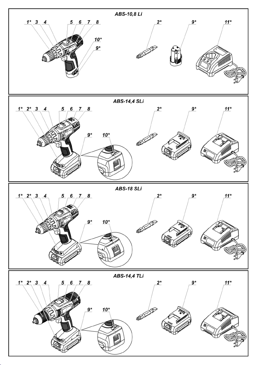
1Schnellspannfutter *
2Schraubendreher-Bit *
3LED Leuchte
4Drehmomentregler
5Drehzahlstufenschalter
6Ein- / Ausschalter
7Umkehrschalter
8Lüftungsschlitze
9Akku *
10Akkuverriegelung *
11Ladegerät *
12Schraube *
9
79,33
0,63
Elektrowerkzeug
Einzelteile
82,80
1,19
13Magnethalter *•Akku vor Temperaturen über 45°С und längerer
14Typenschild des Ladegeräts *
15Anzeige (rot) *
16Anzeige (grün) *
17Anzeige des Akkuladestands *
18Kontrollschalter des Akkuladestands *
* Zubehör
Abgebildetes oder beschriebenes Zubehör gehört
teilweise nicht zum Lieferumfang.
Empfohlenes Zubehör
DWT
Sie können das empfohlene DWT Zubehör auf der
Seite Nr 124-133 der Anleitung finden. Die breite
Auswah l des Zubehörs wird Ihnen ermöglichen,
Aufgab en jeglicher Art effekti v zu erledigen.
Elektrowerkzeug - Bestimmungsgemäßer
Gebrauch DWT
Akkubohrer/-schraubendreher dienen dazu,
Bohrlöcher in Holz, Kunststoff und Metall herzustellen
sowie Befestigungsteile mit Gewinde (z. B. Schrauben)
einzudrehen oder anzuziehen.
Sicherheitsrichtlinien für Arbeiten mit
Elektrowerkzeugen
Spezielle Sicherheitsvorschriften für
Elektrowerkzeuge mit Akkubetrieb
•Nutzen Sie nur originale Ladegeräte und Akkus, die
von DWT stammen.
•Benutzen Sie das Elektrowerkzeug nur mit speziell
dafür entwickelten Akkus. Die Benutzung von anderen
Akkus kann zu Verletzungen und Feuer führen.
Achtung! Kurzschlüsse können zu
Verletzungen führen oder zur
Selbstentzündung. Um dies zu
vermeiden, müssen folgende
Sicherheitsmaßregeln eingehalten
werden:
•Akku nicht zerlegen und nicht umbauen;
•Akku weder im Regen noch in Umgebungen mit
hoher Luftfeuchtigkeit laden;
•Akku nicht laden, wenn das Gehäuse beschädigt ist;
•Akkukontakte nicht kurzschließen;
•Akku nicht mit kleinen Metallgegenständen (z. B.
Nägel, Drähte usw.) in Berührung bringen, wenn er
nicht in das Elektrowerkzeug eingesetzt ist, um die
Akkukontakte nicht kurzzuschließen.
•Der Akku wird beim Laden warm und darf deshalb
nicht abgedeckt oder auf eine isolierende Unterlage
gestellt werden (Mineralwolle, Sägestaub usw.).
Sonneneinstrahlung schützen; nicht ins Feuer werfen -
Explosionsgefahr.
•Überladen oder Überhitzen kann dazu führen, dass
ätzende Flüssigkeit austritt, die zu Verätzungen führt -
deshalb Hautkontakt vermeiden.
•Im Falle einer Beschädigung des Akkugehäuses
oder falscher Verwendung wird wahrscheinlich ein Gas
austreten, das auf das Atmungssystem reizend wirken
kann. Atmen Sie das Gas nicht ein, sorgen Sie für
frische Luft und konsultieren Sie bei Bedarf einen Arzt.
•Benutzen Sie keine beschädigten Akkus oder
Ladegeräte, dies könnte zur Beschädigung des
Elektrowerkzeugs und so zu Verletzungen oder
Materialschäden führen.
•Defekte oder unbrauchbare Akkus auf keinen Fall mit
dem normalen Hausmüll entsorgen, sondern zu einem
Recyclinghof bringen.
Beim Betrieb
•Den Motor nicht unter Last anhalten.
•Das Entfernen von Spänen bei laufendem
Elektrowerkzeug ist strengstens verboten.
•Vergewissern Sie sich vor Beginn der Arbeiten, wo
Elektro-, Gas- und Wasserleitungen verlegt sind. Eine
Beschädigung von elektrischen Leitungen o der
Telefonleitungen kann Leben und Gesundheit des
Bedieners ernsthaft in Gefahr bringen.
•Falls sich das Durchtrennen von Netzleitungen im
Arbeitsplan nicht vermeiden lässt, die Netzleitungen
unbedingt vorher abschalten.
•Erleichtern Sie sich die Arbeit, indem Sie nur scharfe,
intakte Bohrer verwenden.
•Jegliche Manipulation an den Bohrern sowie die
Verwendung von Adaptern und Zubehörteilen, die nicht
für das Elektrowerkzeug konzipiert sind, ist strengstens
untersagt.
•Wenden Sie beim Bohren keinen übermäßigen
Druck an, andernfalls kann der Bohrer blockieren oder
der Motor wird überlastet.
•Achten Sie darauf, dass der Bohrer nicht im Material
blockiert. Niemals versuchen, festsitzende Bohrer
mithilfe des Elektrowerkzeugs zu lösen. Andernfalls
kann das Elektrowerkzeug Schaden nehmen.
•Das Herausschlagen eines festsitzenden Bohrers mit
einem Hammer oder einem anderen Gegenstand ist
strengstens verboten - die B edienperson oder
unbeteiligte Dritte könnten von umher fliegenden
Metallteilen verletzt werden.
•Verarbeiten Sie keine asbesthaltigen Materialien.
Asbest gilt als krebserregend.
Installation und Regelung
der Elektrowerkzeugteile
Zuerst muss der Umschalter 7 in die Mitte
geschoben werden.
Befestigungselemente nicht zu stark
anziehen, um das Gewinde nicht zu
beschädigen.
Deutsch
10
Monta ge / Demontage / Aufstellung •Drücken Sie die Akkuverriegelung 10 (ABS-10,8 Li -
einiger Elemente ist für alle zwei Akkuverriegelungen 10), entfernen Sie den Akku 9
Elektrowerkzeug-Modell e gleich, in und setzen Sie ihn in das Ladegerät 11 ein (siehe Abb. 8 -9).
diesem Fall sind in der Abbildung keine •Wenn der Akku vollständig geladen ist entfernen Sie
besonderen Modelle angezeigt.den Akku 9 aus dem Ladegerät 11 und montieren Sie
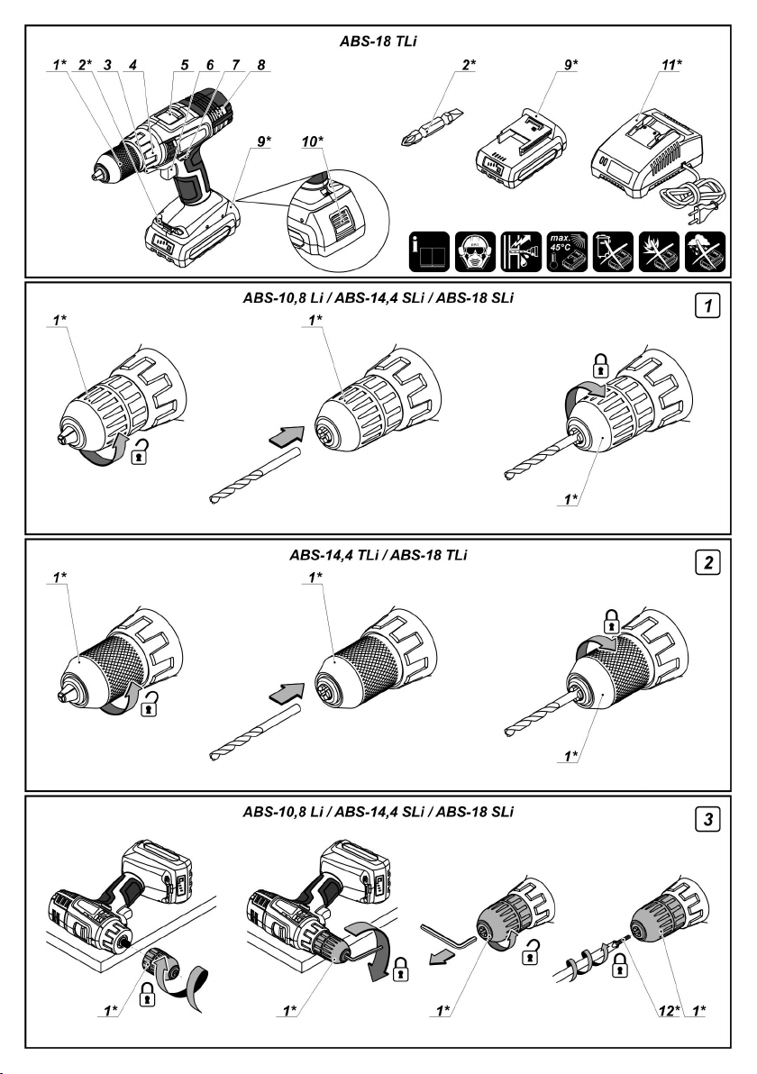
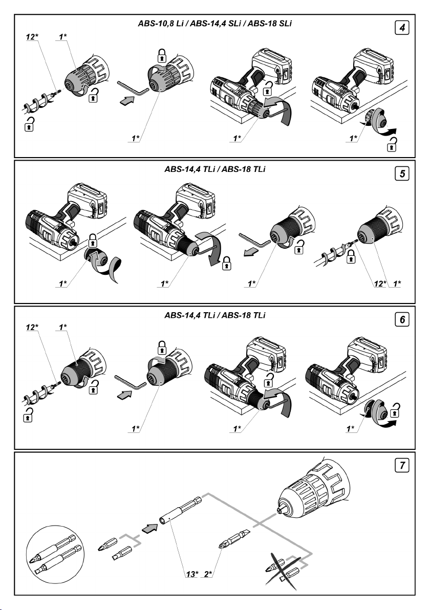
Montage / Austausch von Werkzeug (siehe Abb. 1-2)•Schalten Sie das Ladegerät 11 nach der Benutzung ab.
Der Bohrer wird bei längerem Gebrauch Ladegerät Anzeigen (siehe Abb. 10)
warm und darf nur mit Handschuhen
angefasst werden.Die Anzeigen des Ladegeräts 15 und 16 informieren
•Öffnen Sie die Backen des Schnellspannbohrfutters 1 Anzeigen 15 und 16 werden auf dem Typenschild 14
indem Sie den vorderen Teil wie in Abb. 1-2 gezeigt angezeigt (siehe Abb. 10.1-10.5).
drehen.•Abb. 10.1 - (die grüne Anzeige 16 ist an, der Akku 9 ist
•Werkzeug montieren oder austauschen.nicht im Ladegerät 11) - das Ladegerät 11 ist am
•Ziehen Sie das Schnellspannbohrfutter 1 fest ohne Stromnetz angeschlossen.
das Zubehör zu verdrehen, wie in Abb. 1-2 gezeigt.•Abb. 10.2 - (die rote Anzeige 15 ist an, der Akku 9 ist
Montage / Demontage des Schnellspannfutters •Abb. 10.3 - (die grüne Anzeige 16 ist an, der Akku 9 ist
(siehe Abb. 3-6)im Ladegerät 11) - der Akku 9 ist vollständig geladen.
•Um das Schnellspannbohrfutter 1 zu montieren ist im Ladegerät 11) - der Ladeprozess des Akkus 9
führen Sie die Schritte, die in Abb. 3-5 gezeigt werden, wurde aufgrund ungeeigneter Temperaturen
in fortlaufender Reihenfolge durch.angehalten. Wenn sich die Temperatur normalisiert hat
•Um das Schnellspannbohrfutter 1 zu demontieren wird der Ladeprozess fortgesetzt.
führen Sie die Schritte, die in Abb. 4-6 gezeigt werden, •Abb. 10.5 - die rote Anzeige 15 blinkt, der Akku 9 ist
in fortlaufender Reihenfolge durch.im Ladegerät 11) - der Ladeprozess des Akkus 9 wurde
Achtung: Achten Sie bei der Montage / Sie den fehlerhaften Akku 9, er darf nicht mehr benutzt
Demontage des Schnellspannfutters 1 werden.
darauf, dass Schraube 12 ein
Linksgewinde hat.Beim Ladeprozess erhitzen sich der Akku 9
Schraubendreher-Bit / Magnethalter (siehe Abb. 7)normaler Prozess.
ihn im Elektrowerkzeug.
Sie über den Akkuladeprozess. Die Signale der
im Ladegerät 11) - der Akku 9 wird geladen.
•Abb. 10.4 - (die grüne Anzeige 16 blinkt, der Akku 9
aufgrund eines fehlerhaften Akkus beendet. Ersetzen
und das Ladegerät 11, das i st ein
Für kurze Schraubendreher-Bits benutzen Sie den Ein- / Ausschalten
magnetischen Halter 13, um sie zuverlässig zu fixieren des Elektrowerkzeuges
(siehe Abb. 7).
Für lange Schraubendreher-Bits 2 (speziell für Sicherstellen, dass sich der Umschalter 7 nicht in
Schraubendreher) wird kein Magnethalter 13 benötigt.der mittleren Position befindet; andernfalls ist der
Laden
des AkkusEinschalten:
Erste Inbetriebnahme des ElektrowerkzeugesAusschalten:
Das Elektrowerkzeug wird mit einem teilweise
geladenen Akku 9 geliefert. Der Akku 9 muss vor Funktionsmerkmale
der ersten Nutzung vollständig geladen werden.des Elektrowerkzeugs
Der Akku 9 muss bei geeigneter Akku (siehe Abb. 11)
Temperatur (von 0° C bis 45° C) geladen
werden.•Li-Ionen Akku 9 kann jederzeit in das Ladegerät 11
Ladevorgang (siehe Abb. 8-9)(unabhängig vom Ladestatus) - die Lebenszeit wird
•Umschalter 7 in die Mitte schieben.Leistungsverlust.
•Verbinden Sie das Ladegerät 11 mit der •Der Akku 9 wird von einem Sicherheitssystem vor
Stromversorgung.Tiefentladung geschützt. Im Falle einer vollständigen
Ein- / Ausschalter 6 blockiert.
Ein- / Ausschalter 6 drücken.
Ein- / Ausschalter 6 loslassen.
eingelegt oder daraus entnommen werden
davon nicht beeinträchtig und es entsteht kein
Deutsch
11
Entladung schaltet das Elektrowerkzeug automatisch Umschalten der Drehrichtung (siehe Abb. 12)
ab. Achtung: Versuchen Si e nicht das
Elektrowerkzeug anzuschalten, wenn das Die Drehrichtung darf erst geändert
Sicherheitssystem aktiviert wurde, der Akku 9 werden, wenn der Motor völlig zum
könnte beschädigt werden.Stillstand gekommen ist; andernfalls
[ABS-14,4 SLi, ABS-18 SLi, ABS-14,4 TLi, ABS-18 TLi]werden.
Beim Drücken des Schalters 18 zeigen die Anzeigen 17 Drehrichtung im Uhrzeigersinn (Bohren, Eindrehen
den Status der Akkuladung 9 an (siehe Abb. 11).von Schrauben) - Umschalter 7 nach links schieben,
siehe Abbildung 12.
Temperaturschutz
Drehrichtung im Gegenuhrzeigersinn (Lösen von
Das Temperaturschutzsystem ermöglicht die Schrauben) - Umschalter 7 nach rechts schieben, siehe
automatische Abschaltung des Elektrowerkzeugs im Abbildung 12.
Falle einer Überladung oder falls der Akku 9 eine
Temperatur von 70° C übersteigt. Das System garantiert Automatische Spindelsperre
den Schutz des Elektrowerkzeugs vor Schäden im Falle
einer Nichteinhaltung der Arbeitskonditionen.Wenn der Ein- / Ausschalter 6 nicht gedrückt wird ist die
Spindel des Elekt rowerkzeugs gesperrt. Dies
LED Leuchteermöglicht es Ihnen, das Elektrowerkzeug als normalen
Schraubdreher zu benutzen (so kann es zum Bespiel
Wenn der Ein- / Ausschalter 6 gedrückt wird, wird zum manuellen Festziehen von Schrauben benutzt
automatisch die LED Leuchte 3 eingeschaltet, so werden, wenn der Akku fast leer ist).
können auch Arbeiten bei schwachem Licht ausgeführt
werden.Schnellstoppfunktion
kann das Elektrowerkzeug beschädigt
DrehmomentreglerDie Schnellstoppfunktion sorgt dafür, dass das
Mit dem Regler 4 wird von insgesamt 18 Elektrowerkzeug ausgeschaltet wird. Au f diese Weise
Drehmomentstufen die am besten geeignete wird ein zu starkes Anziehen von Schrauben und
ausgewählt.damit eine Beschädigungen von Werkstücken,
Für Bohrarbeiten sollte der vermieden.
Drehm omentregler 4 in die Position
"Bo hren" gestellt werden.Tipps zum Arbeiten
Stufenlose Geschwindigkeitsregelung
Die Drehzahl wird durch den Anpressdruck
auf den Ein- / Ausschalter 6 gesteuert (0 bis •Bohrerbit regelmäßig schmieren, wenn in Metall
max.). Ein leichter Druck s tellt einegebohrt wird (außer Nichteisenmetalle und deren
niedrige Drehzahl ein, und ermöglicht ein Legierungen).
sanftes Anlaufen das Elektrowerkzeug.•Beim Bohren in harten Metallen den Druck auf das
Drehzahlstufenschalter geschwindigkeit herabsetzen.
Achtung: Zur Veränderung der gewünschten Durchmesser erweitern (siehe Abb. 13).
eingestellten Drehzahl muss der Motor •Um ein Absplittern der Oberfläche beim Bohren in Holz
völlig still s tehen.zu vermeiden, wie in Abbildung 13 gezeigt vorgehen.
Um den ersten Gang einzulegen schieben Sie den Wänden und Decken kann durch die in Abbildung 14
Schalter 5 nach vorne. Dieser Modus wird zum gezeigten Maßnahmen verhütet werden.
Festziehen von Schrauben oder zum Bohren von
Löchern mit großem Durchmesser benutzt.Eindrehen von Schrauben (siehe Abb. 15)
Um den zweiten Gang einzulegen schieben Sie den •Schrauben lassen sich leichter eindrehen, wenn
Schalter 5 zurück. Dieser Modus wird zum zuerst eine Loch mit etwa 2/3 des Durchmessers der
Schnellbohren oder dem Bohren von Löchern mit Schraube vorgebohrt wird. Zudem wird verhindert,
kleinem Durchmesser benutzt.dass das Werkstück bricht.
Spannfutter 1 sofort anhält, wenn das
Schraubendreherbits und Gewindelöchern
mit Elektrowerkzeugen
Bohren (siehe Abb. 13-14)
Elektrowerkzeug erhöhen und die Umdrehungs-
•Große Löcher in Metall zuerst vorbohren und auf den
•Übermäßige Staubentwicklung beim Bohren in
Deutsch
12

•Um Werkstücke, die verschraubt werden sollen, Laufzeiten des Elektrowerkzeugs sind ein Hinweis
dau erhaft mite inander zu verbinden, ohne dass die darauf, dass der Akku 9 verschlissen ist und
Sch raublöcher reißen, brechen oder aufsplittern, ausgetauscht werden sollte. Beachten Sie, dass sich
die in Abbildung 15 gezeigten Maßnahmen der Akku 9 bei Temperaturen unter 0 °C schneller
bef olgen.entlädt.
Elektrowerkzeug - Wartunggelagert wurde wird empfohlen, den Akku bei
und vorbeugende MaßnahmenRaumtemperatur zu lagern, die Akkuladung sollte bei
Zuerst muss der Umschalter 7 in die Mitte
geschoben werden.Reinigung des Elektrowerkzeuges
Falls das Elektrowerkzeug lange ohne Benutzung
50 % liegen.
AkkuDie regelmäßige Reinigung Ihres Elektrowerkzeugs ist
Verschlissene Akkus rechtzeitig ersetzen. Lebensdauer. Reinigen Sie das Elektrowerkzeug,
Nachlassende Leistung oder deutlich kürze re indem Sie Druckluft durch die Luftschlitze 8 blasen.
eine unerlässliche Voraussetzung für lange
Änderungen vorbehalten.
Deutsch
13

Power tool specifications
Cordless drill / screwdriver
Power tool
code
[127 V ~50/60 Hz]
[230 V ~50/60 Hz]
Rated voltage
No-load speed:
- first gear
- second gear
Battery type
Battery charging time
Battery capacity
Turndown of rotation
torque
Number of stages of
rotation torque
Chuck tightening range
Drilling output:
- wood
- steel
Max. screw diameter
Weight
Sound pressure
[V]
[RPM]
[RPM]
[h]
[Ah]
[Nm]
[mm]
[inches]
[mm]
[inches]
[mm]
[inches]
[mm]
[inches]
[kg]
[lbs]
[dB(A)]
ABS-10,8 LiABS-14,4 SLiABS-18 SLi
133033
123034
133040
123041
133057
123058
10,814,418
0-3500-3500-350
0-12500-12500-1250
Li-IonLi-IonLi-Ion
111
1,301,501,50
1-221-251-28
18+118+118+1
1-10
3/64"-25/64"
20
25/32"
10
25/64"
6
15/64"
1,00
2.20
67,2768,33
1-10
3/64"-25/64"
25
63/64"
10
25/64"
6
15/64"
1,23
2.70
1-10
3/64"-25/64"
30
1-3/16"
10
25/64"
7
9/32"
1,29
2.84
71,80
ABS-14,4 TLiABS-18 TLi
132173
122174
132180
122181
14,418
0-3500-350
0-14000-1400
Li-IonLi-Ion
11
1,501,50
1,50-40
1,50-45
18+118+1
1,50-13
1/16"-33/64"
30
1-3/16"
13
33/64"
8
5/16"
1,63
3.59
68,33
1,50-13
1/16"-33/64"
32
1-17/64"
13
33/64"
10
25/64"
1,71
3.77
71,80
Acoustic power
Weighted vibration
[dB(A)]
[m/s]
78,2779,33
2
2,050,63
DWTPower tool
with compliments!components
Dear Customer,
DWT offers a wide ra nge of power tools. Quality
an d reasonable prices are solution for many repair
an d building tasks at home and industry. We hope
th at our power tool will serve you for many years.
Al l detailed information about our power tools and
services you can find on our web page
www.dwt-pt.com.
The DWT team.
English
82,80
1,19
1Keyless chuck *
2Screwdriver bit *
3LED lamp
4Torque regulator
5Step speed selector switch
6On / off switch
7Reverse switch
8Ventilation slots
9Battery *
10Battery lock *
14
79,33
0,63
82,80
1,19
11Charger *•Overdraft or overheating may cause discharge of
12Screw *
13Magnetic holder *
14Charger label *
15Indicator (red) *
16Indicator (green) *
17Indicators of the state of battery charge *
18Control button of the state of battery charge *
* Optional extra
Not all of the accessories illustrated or described
are included as standard delivery.
Recommended accessories
DWT
You can find the recommended DWT accessories on
the page 124-133 of the instruction. The bright range of
the accessories will allow you to perform necessary
kinds of works effectively.
DWT
power tool designation
Cordless drills / screwdrivers are designed for hole
drilling in wood, plastic and metal, as well as for
screwing in and loosening of threaded fastening
elements (screws, bolts, etc.).
Safety guidelines during
power tool operation
Specific safety rules for cordless power tools
•Use only original chargers and batteries delivered by
DWT.
•Use power tools only with specifically designated
batteries. Use of any other batteries may create a risk of
injury and fire.
Attention! Short circuit can cause injuries
to the user; it can cause a fire as well. In
order to avoid this, observe the following
rules:
•do not disassemble the battery and do not change
caustic liquid, which may cause chemical burns;
therefore, avoid contact with skin.
•In case of damage of battery housing or its improper
use, the emission of gas is probable that can be irritating
for the respiratory system do not inhale the gas, provide
supply of fresh air, and consult the doctor if necessary.
•Do not use damaged batteries and chargers their
use can lead to damage of the power tool and result in
injuries or material damage.
•It is absolutely forbidden to throw defective or
unworkable batteries into household garbage; they
should be collected and brought for recycling or
ecologically clean utilization.
During operation
•Avoid electric tool motor stop, when loaded.
•Removing chips with the power tool engine running is
strictly forbidden.
•Before starting work, make sure where hidden
electric cables and water and gas pipes are situated.
Damaging the electric supply wiring or engineering
communications may cause a severe harm to the
operator's life and health.
•If the working schedule cannot exclude damaging the
main supply cables, they have to be de-energized.
•Use only sharp drills without defects - it will make
working with the power tool easier.
•The modification of the dr ills design and the use of
remova ble orifices and accessories not envisaged for
this power tool is strictly forbidden.
•Do not apply excessive pressure when operating the
power tool - it can jam the drill and overload the engine.
•Do not allow drills to jam in the material processed. If this
occurs, do not try to release them by means of the power
tool engine. This can put the power tool out of order.
•Striking out drills jammed in the material processed with a
hammer or other objects is strictly forbidden - metal fragments
can hurt both the operator and the people nearby.
•Never treat workpieces containing asbestos.
Asbestos is cosidered carcinogenic.
Installation and regulation
of power tool elements
Before execution of any procedures, centre the
reverse switch 7.
its construction;
•do not charge the battery in the high humidity
environment or outdoor during rainfall;
•do not charge the battery when a battery jar is
damaged;
•do not short battery poles;
•keep a battery detached from a power tool away
from small metal objects (nails, wire, etc.), which can
short battery poles.
•In the process of charging, the battery gets warm;
the refore, do not cover it and do not place it on
the rmal insulation materials (mineral wool, sawdust,
etc.).
Mounting / replacement of accessories (see fig.1-2)
Do not draw up the fastening elements
too tight to avoid damaging the thread.
Mounting / dismounting / setting-up of
some elements is the same for all power
tool models, in this case specific models
are not indicated in the illustration.
With long-term use the drill bit m ay
become very warm; use gloves to
remove it.
•Avoid heating of the battery above 45°С. Prevent
long-term exposure to direct sunlight and never throw
the battery into a fire as it might explode.
•Open the jaws of the keyless chuck 1, rotating its front
part as shown in figures 1-2.
English
15
•Mount / replace the accessory.•Fig. 10.4 - (the green indicator 16 is blinking, the
•Tighten the keyless chuck 1 without skewing the
accessory as it is shown in figures 1-2.
Mounting / dismounting of the keyless chuck (see
fig. 3-6)
•To mount the keyless chuck 1, carry out the
operations in consecutive stages as it is shown in
figures 3-5.
•To dismount the keyless chuck 1, carry out the
operations in consecutive stages as it is shown in
figures 4-6.
Attention: keep in mind that in the
process of mounting / dismounting of the
keyless chuck 1 the screw 12 has a left-
hand thread.
Screwdriver bit / magnetic holder (see fig. 7)
For short screwdriver bits use the magnetic
holder 13 for their reliable fixing (see fig. 7).
A magnetic holder 13 is not needed for extended
s crewdriver bits 2 (specially purposed for
screwdrivers).
Charging procedure
of the power tool battery
Initial operation of the power tools
The power tool is supplied with a partially charged
battery 9. Before the first use, the battery 9 must be
fully charged.
The battery 9 must be ch arged in the
ap propriate temperature (from 0°C t o
45 °C).
Charging process (see fig. 8-9)
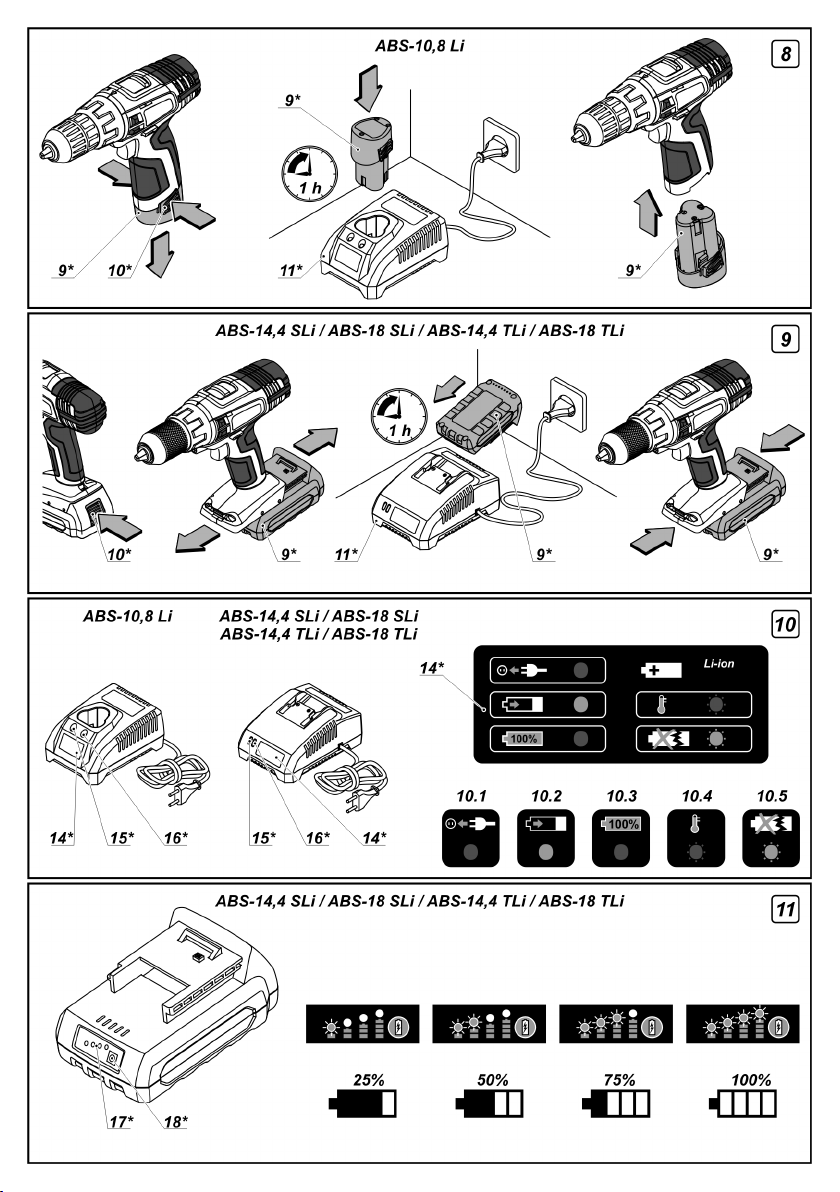
•Centre the reverse switch 7.
•Connect the charger 11 to the power supply.
•Press the battery lock 10 (ABS-10,8 Li - two battery
locks 10), remove the battery 9 and insert it in the
charger 11 (see fig. 8-9).
•When battery is fully charged, disconnect the battery 9
from the charger 11 and mount it in the power tool.
•Switch off the charger 11 after use.
Charger indicators (see fig. 10)
Charger indicators 15 and 16 inform of the battery 9
charging process. Signals of the indicators 15 and 16
are shown on the label 14 (see fig. 10.1-10.5).
•Fig. 10.1 - (the green indicator 16 is on, the battery 9 is
not inserted in the charger 11) - the charger 11 is
connected to the power network.
•Fig. 10.2 - (the red indicator 15 is on, the battery 9 is
inserted in the charger 11) - the battery 9 is being charged.
•Fig. 10.3 - (the green indicator 16 is on, the battery 9 is
inserted in the charger 11) - the battery 9 is fully charged.
battery 9 is inserted in the charger 11) - the charging
process of the battery 9 is terminated due to
inappropriate temperature. When the temperature
conditions are normal, the process of charging will
resume.
•Fig. 10.5 - (the red indicator 15 is blinking, the battery 9
is inserted in the charger 11) - the charging process of
the battery 9 is terminated because of its failure.
Replace the faulty battery 9, its further use is prohibited.
In the process of charging the battery 9
and the charger 11 become hot, it is a
normal process.
Switching the power
tool on / off
Make sure that the reverse switch 7 is not centred;
this blocks on / off switch 6.
Switching on:
Press on / off switch 6.
Switching off:
Release the on / off switch 6.
Design features
of the power tool
Battery (see fig. 11)
•Li-Ion battery 9 can be put on and remove from
charger 11 at any time (regardless of the charging state) -
it does not affect its service life and it does not lead to
the loss of its capacity.
•The battery 9 is protected by the safety system
against deep discharge. In case of complete discharge,
the power tool is automatically switched off. Attention:
do not try to switch on the power tool when the
protection system is activated the battery 9 can be
damaged.
[ABS-14,4 SLi, ABS-18 SLi, ABS-14,4 TLi, ABS-18 TLi]
With the push of the button 18 the indicators 17 show
the state of charge of the battery 9 (see fig. 11).
Temperature protection
The temperature protection system enables to
automatically deactivate the power tool in case of
excess load or when the temperature of the battery 9 is
exceeding 70°C. The system guarantees protection of
the power tool from damage in case of noncompliance
with the operation conditions.
LED lamp
When the on / off switch 6 is pushed, the LED lamp 3 is
automatically switched on that allows to carry out works
in low light conditions.
Torque regulator
Rotate the regulator 4 in order to set one of the 18
torque values most suitable for the work performed.
English
16
It is recommended to set the torque regulator 4
into the position "Drill" to perform drilling.
Stepless speed adjustment
Speed is controlled from 0 to maximum by
pressi ng force of on / off switch 6. Weak
pressi ng results in low revolutions, which
enable a smooth power tool switch-on.
Step speed selector switch
Attention: one can only change the
revolutions per minute range after the
engine fully stops.
In order to put in the first gear, move the switch 5
forward. This mode is used for the fastening of screws
or for large diameter hole drilling.
In order to put in the second gear, move the switch 5
back. This mode is used for speed drilling of small
diameter holes.
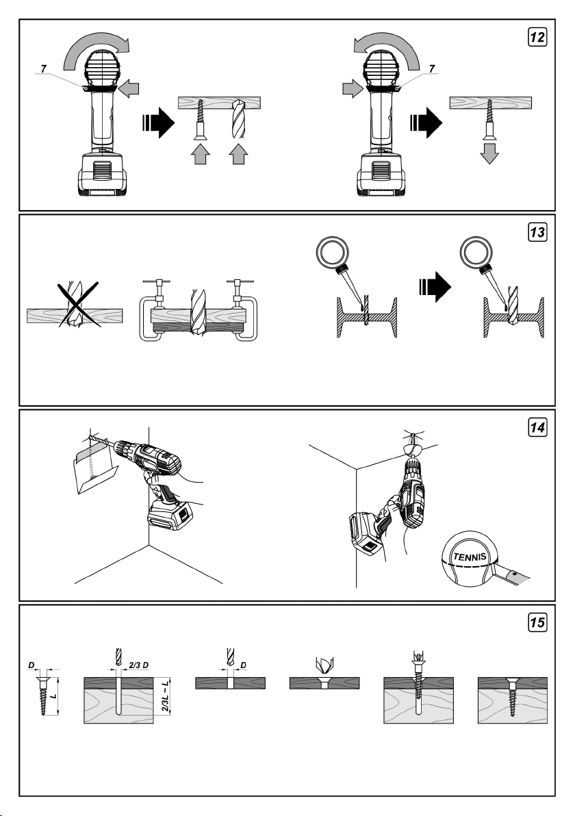
Changing the rotational directions (see fig. 12)
Change the direction of rotation only after
a full stop of the motor, acting otherwise
may cause damage to the power tool.
Clockwise rotation (drilling, fastening of screws) -
move the reverse switch 7 to the left as it is shown in
fig. 12.
Counter clockwise rotation (unscrewing the
screws ) - move the reverse switch 7 to the right as it is
shown in fig. 12.
Spindle automatic locking
If the on-off switch 6 is not pressed, the spindle of the
power tool is locked this enables to use the power tool
as an ordinary screwdriver (for example it can be used
to tighten manually screws or bolts, if the battery is low).
Break rundown
Break rundown stops the keyless chuck 1 immediately
after the power tool is turned off. This helps to avoid an
excessive tightening of the bolts and screws and
prevents work pieces, screwdriver bits and slots of
fastening elements from being damaged.
Recommendations
on the power tool operation
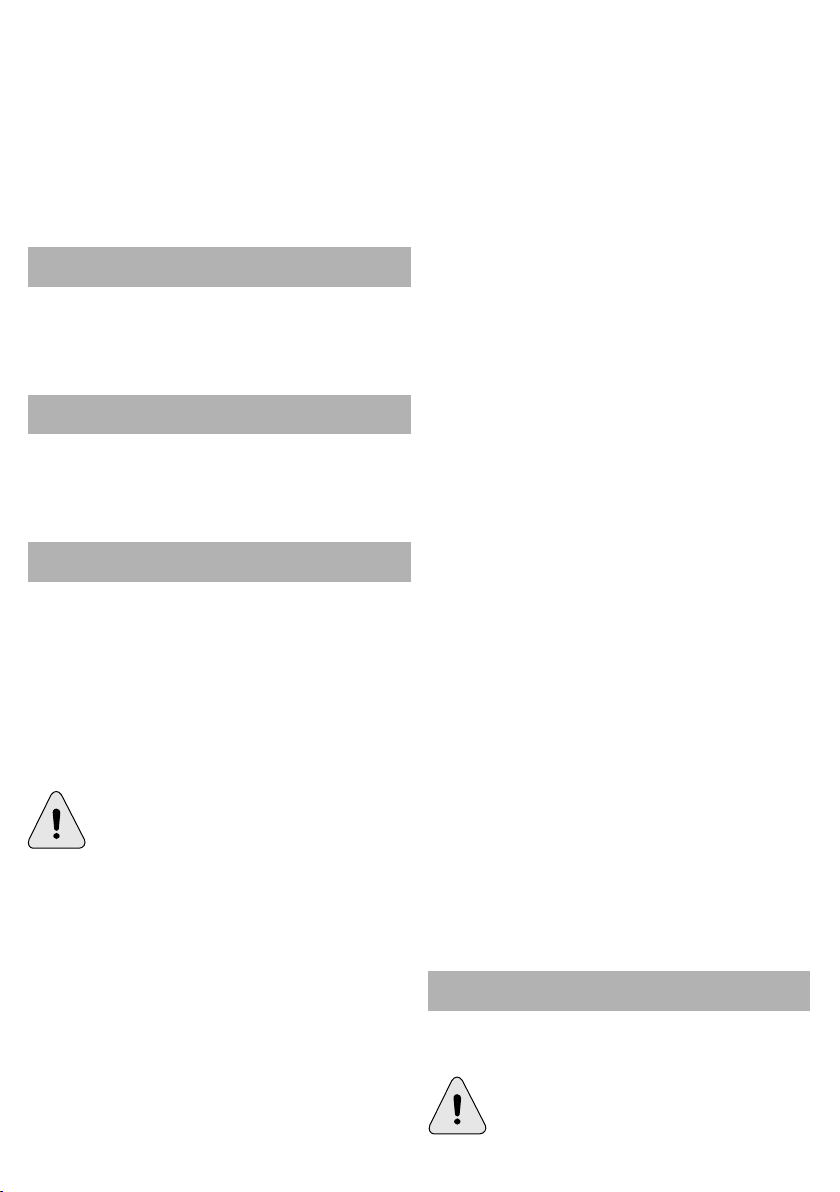
Drilling (see fig. 13-14)
•Grease the drill bit regularly when drilling holes in
metals (except drilling non-ferrous metals and their
alloys).
•When drilling hard metals, apply more force to the
power tool and lower the rotation speed.
•When drilling large diameter holes in metal, first drill a
hole with a smaller diameter and ream it till the
necessary diameter (see. fig. 13).
•In order to avoid splitting of the surface at an exit point
of a drill bit when drilling holes in wood, follow the
instructions shown in figure 13.
•In order to decrease dust production when drilling
holes in walls and ceilings, take actions indicated in
figure 14.
Screwing the screws (see fig. 15)
•To make fastening of screws easier and in order to
prevent cracking of the work pieces, first drill a hole with
a diameter equal to 2/3 of a diameter of the screw.
•If you are connecting work pieces with the help of
screws, in order to achieve durable joint without getting
cracks, fracturing or layering, take actions shown in
figure 15.
Power tool maintenance /
preventive measures
Before execution of any procedures, centre the
reverse switch 7.
Battery
Replace worn out batteries in time. Decline of
production or a significantly shorter runtime of the
power tool after charging indicates aging of the battery 9
and the need for replacement. It should be taken into
account that the battery 9 may discharge faster if the
works take place in the temperature below 0°С.
In case of long time storage without use, it is
recommended to store the bat tery 9 at room
temperature, it should be charged to 50%.
Cleaning of the power tool
An indispensable condition for a safe long-term
exploitation of the power tool is to keep it clean.
Regularly flush the power tool with compressed air
thought the ventilation slots 8.
The manufacturer reserves the possibility to introduce changes.
English
17

Spécifications de l'outil électrique
Taraudeuse a pile rechargeable
Code de l'outil
électrique
[127 V ~50/60 Hz]
[230 V ~50/60 Hz]
Voltage gradué
Régime à vide:
- première vitesse
- seconde vitesse
[min]
[min]
Type de batterie
Temps de chargement
de la batterie
Capacité de la batterie
Couple de rotation
[Nm]
Nombre de tours du
couple de rotation
Plage de resserrement
du mandrin
[mm]
[pouces]
Puissance de perçage:
- bois
- acier
Max. diamètre de la vis
Poids
Pression acoustique
[mm]
[pouces]
[mm]
[pouces]
[mm]
[pouces]
[lbs]
[dB(A)]
ABS-10,8 LiABS-14,4 SLiABS-18 SLi
133033
123034
[V]
10,814,418
-1
0-3500-3500-350
-1
0-12500-12500-1250
133040
123041
Li-IonLi-IonLi-Ion
[h]
[Ah]
111
1,301,501,50
1-221-251-28
18+118+118+1
[kg]
1-10
3/64"-25/64"
20
25/32"
10
25/64"
6
15/64"
1,00
2.20
1-10
3/64"-25/64"
25
63/64"
10
25/64"
6
15/64"
1,23
2.70
67,2768,33
133057
123058
1-10
3/64"-25/64"
30
1-3/16"
10
25/64"
7
9/32"
1,29
2.84
71,80
ABS-14,4 TLiABS-18 TLi
132173
122174
132180
122181
14,418
0-3500-350
0-14000-1400
Li-IonLi-Ion
11
1,501,50
1,50-40
1,50-45
18+118+1
1,50-13
1/16"-33/64"
30
1-3/16"
13
33/64"
8
5/16"
1,63
3.59
68,33
1,50-13
1/16"-33/64"
32
1-17/64"
13
33/64"
10
25/64"
1,71
3.77
71,80
Puissance acoustique
Vibration
[dB(A)]
[m/s]
78,2779,33
2
2,050,63
Avec les compliments de
DWT!
Cher client,
DWT vous offre une vaste gamme d'outils électriques.
Grace à la qualité et les prix abordables ils sont une
bonne solution en cas des travaux de construction ou
de rénovation. Nous espérons que vous profiterez avec
une joie de l'utilisation de ces outils électriques pendant
de nombreuses années. Vous pouvez trouver des
informations supplémentaires sur nos outils
électriques et nos services sur notre site internet
www.dwt-pt.com.
DWT, toujours à votre service.
Français
82,80
1,19
79,33
0,63
Composants
de l'outil électrique
1Mandrin auto-serrant *
2Embout de tournevis *
3Voyant LED
4Régulateur de couple
5Sélecteur de vitesse étape par étape
6Interrupteur marche / arrêt
7Interrupteur de sens inverse
8Fentes d'aération
9Batterie *
10Système de blocage de la batterie *
11Chargeur *
12Vis *
18
82,80
1,19
13Aimant de retenue *
14Étiquette du chargeur *
15Voyant (rouge) *
16Voyant (vert) *
17Voyant de charge de la batterie *
18Bouton de contrôle de charge de la batterie *
* Accessoires
Une partie des accessoires représentés et décrits
ne figurent pas dans la livraison.
Accessoires recommandés
Vous pouvez trouver les accessoires DWT
reccomandés à la page 124-133 du manuel. La vaste
gamme d'accessoires vous permetra d'effectuer
chaque type de travail.
Désignation de l'outil électrique
Les visseuses / perceuses sans fil sont conçues pour
percer dans le bois, le plastique et le métal, elles
peuvent également visser ou dévisser les fixations à
filetage (vis, boulons).
Directives de sécurité pendant l'utilisation de
Règles de sécurité spécifiques pour les outils
électriques sans fil
•N'utilisez que des chargeurs et batteries vendus par
DWT.
•N'utilisez que des outils électrique n'ayant que des
batteries bien spécifiques. L'utilisation d'autres
batteries peut entrainer des risques d'incendie ou de
blessures.
Avertissement! Le fait de créer un court-
circuit peut de sérieux dommages à
l'utilisateur. Veuillez suivre les consignes
suivantes:
•ne pas démonter ou modifier l'intérieur de la
batterie;
•ne pas recharger la batterie d ans un
environnement humide ou à l'extérieur lorsqu'il pleut;
•ne pas recharger la batterie lorsque sa jauge est
endommagée;
•ne pas court-circuiter les bornes de la batterie;
•lorsqu'on ne sert pas de la batterie de l'outil
électrique, l'éloigner des petits objets métalliques,
par exemple trombones, fils électriques etc. Qui
peuvent créer une connexion entre deux bornes.
•Durant la phase de chargement, la batterie chauffe ;
ne cherchez pas à couvrir ou à la placer sur des
matériaux conducteurs thermiques (fibres minérales,
sciure de bois etc.).
•Eviter une surchauffe de la batterie au-delà de 45°С.
Evitez toute exposition prolongée au soleil et ne jamais jeter
la batterie dans le feu, cela peut provoquer une explosion.
•Une surchauffe ou la manque d'aération peut
provoquer l'émission de liquide caustique ou constituer
un risque de brûlure chimique. Evitez tout contact avec
la peau.
DWT
DWT
l'outil électrique
Français
•En cas de dégât du carter de batterie ou d'une
mauvaise utilisation, l'émission de gaz est susceptible
d'irriter le système respiratoire ; ne pas inhaler le gaz,
respirer de l'air frais et consulter un médecin au besoin.
•Ne pas utiliser de batteries et de chargeurs
endommagés car leur utilisation peut nuire à l'outil
électrique et entrainer des blessures ou des dégâts du
matériel.
•Il est strictement interdit de jeter les batteries
défectueuses ou inexploitables dans ses poubelles;
elles doivent être amenées dans des centres de tris
écologiques.
Pendant l'opération
•Évitez d'arrêter le moteur d'un outil électrique
lorsqu'il est sous charge.
•Il est formellement déconseillé de retirer les éclats
lorsque le moteur de la perceuse est en marche.
•Avant de commencer un travail, assurez-vous de
savoir où se trouvent les câbles électriques et les
conduites d'eau et de gaz cachés. Le fait
d'endommager le fil d'alimentation électrique ou la
construction mécanique peut entraîner des blessures
graves ou mettre la vie de l'opérateur en danger.
•Si le programme de travail ne peut pas exclure le fait
d'endommager les câbles d'alimentation principaux,
ceux-ci doivent être mis hors tension.
•N'utiliser que des mèches aiguisées et sans défauts,
cela facilitera le travail de l'outil électrique.
•Il est formellement déconseillé de modifier la conception
des mèches et d'utiliser des orifices amovibles et des
accessoires non prévus pour cet outil électrique.
•Ne pas appliquer de pression excessive lors de
l'utilisation de l'outil électrique - cela pourrait bloquer la
perceuse et surcharger le moteur.
•Ne pas laisser les mèches se bloquer dans le
matériau traité. Si cela se produit, ne pas essayer de les
libérer au moyen du moteur de l'outil. Cela risquerait de
l'endommager.
•Il est formellement déconseillé de frapper sur des
mèches coincées dans le matériau traité avec un marteau
ou tout autre objet - les fragments en métal pourraient
blesser l'opérateur ou les personnes à proximité.
•Ne pas travailler les matériaux contenant de l'asbeste.
L'asbeste possède les propriétés cancérigènes.
Installation et réglage
des éléments de l'outil électrique
Avant l'exécution des procédures, positionnez
l'interrupteur sur 7.
Ne pas trop serrer les fixations afin
d'éviter tout endommagement du filetage.
Le montage / démontage / réglage de
certains éléments est le même que pour
tous les modèles d'outils électriques;
dans ce cas, les modèles spécifiques ne
sont pas indiqués sur l'illustration.
Monter / remplacer les accessoires (voir les fig. 1-2)
Après une utilisation prolongée, le foret
de la perceuse peut ê tre échauffé;
munissez-vous de gants pour le retirer.
19
•Ouvrir les mâchoires du mandrin sans clé 1, faire •Fig. 10.3 - (le voyant vert 16 est allumé, la batterie 9
pivoter l'avant comme indiqué aux figures 1-2.
•Monter / remplacer l'accessoire.
•Visser le mandrin sans clé 1, sans le tordre, comme
indiquer aux figures 1-2.
Monter / remplacer le mandrin sans clavette (voir
les fig. 3-6)
•Pour installer le mandrin sans clé 1, suivre les étapes
consécutives comme indiquées aux figures 3-5.
•Pour déposer le mandrin sans clé 1, suivre les étapes
consécutives comme indiquées aux figures 4-6.
Avertissement: rappelez-vous que
pendant la phase de montage / démontage
du mandrin à clavette 1, la vis 12 a un
filetage positionné à gauche.
Embout de tournevis / aimant de retenue (voir la fig. 7)
Concernant les forets de vissage courts, utilisez la tige
porteuse 13 (voir la fig. 7).
L'aimant de retenue 13 n'est pas nécessaire pour les
embouts de tournevis prolongés 2 (spécialement conçus
pour les tournevis).
Méthode de recharge
de la batterie de l'outil électrique
Première utilisation de l'outil électrique
L'outil électrique est livré avec une batterie 9
partiellement chargée. Avant de commencer à
l'utiliser, il faut la charger complètement.
Elle doit être chargée à la b onne
température (de 0 à 45° C).
Recharge (voir les fig. 8-9)
•Positionner l'interrupteur au centre 7.
•Brancher le chargeur 11 sur l'alimentation.
•Appuyer sur le système de blocage 10 (ABS-10,8 Li -
deux systèmes de blocage 10), déposer la batterie 9 et
la mettre dans le chargeur 11 (voir les fig. 8-9).
•Lorsque la batterie 9 est complètement chargée, la
débrancher du chargeur 11 et l'installer dans l'outil
électrique.
•Éteindre le chargeur 11 après utilisation.
Voyant de charge (voir la fig. 10)
Les voyants 15 et 16 du chargeur indiquent
l'avancement du chargement de la batterie 9. Les
signaux des voyants 15 et 16 sont indiqués sur
l'étiquette 14 (voir les fig. 10.1 - 10.5).
•Fig. 10.1 - (le voyant vert 16 est allumé, la batterie 9
n'est pas mise dans le chargeur 11) - Le chargeur 11 est
branché sur le secteur.
•Fig. 10.2 - (le voyant rouge 15 est allumé, la batterie 9
est mise dans le chargeur 11) - La batterie 9 est en train
de charger.
est mise dans le chargeur 11) - La batterie 9 est
entièrement chargée.
•Fig. 10.4 - (le voyant vert 16 est allumé, la batterie 9
est mise dans le chargeur 11) - Le processus de
chargement de la batterie 9 s'est arrêté en raison d'une
température inappropriée. Lorsque la température est
redevenue normale, le chargement reprend.
•Fig. 10.5 - (le voyant rouge 15 clignote, la batterie 9
est mise dans le chargeur 11) - Le processus de
chargement de la batterie 9 s'est arrêté en raison d'un
dysfonctionnement. Changer la batterie défectueuse 9
car vous ne pouvez plus l'utiliser.
Lors du chargement, la batterie 9 et le
chargeur 11 se mettent à chauffer ; c'est
tout à fait normal.
Mettre en marche / arrêter
l'outil électrique
S'assurer que la position de l'interrupteur 7 n'est
pas au centre; cela permet de verrouiller
l'interrupteur marche / arrêt 6.
Activer:
Appuyer sur l'interrupteur marche / arrêt 6.
Désactiver:
Relâcher l'interrupteur marche / arrêt 6.
Caractéristiques de l'outil
électrique
Batterie (voir la fig. 11)
•Il est possible de mettre une pile Li-Ion 9 et de retirer
le chargeur 11 quand vous le désirez (quel que soit le
niveau de charge) ; cela n'affecte pas sa durée de vie et
ne lui fait pas perdre ses capacités.
•La batterie 9 est protégée par un système de sécurité
contre les pertes de courant. Lorsqu'elle se décharge
complètement, l'outil électrique s'éteint automatiquement.
Attention : ne pas essayer l'interrupteur de l'outil
électrique lorsque le système de protection est allumé
car la batterie 9 peut en être endommagée.
[ABS-14,4 SLi, ABS-18 SLi, ABS-14,4 TLi, ABS-18 TLi]
Si vous appuyez sur le bouton 18, le voyant 17 se met à
indiquer le niveau de charge de la batterie 9 (voir la fig. 11).
Protection contre la température
Le système de protection contre la température permet
de couper automatiquement l'outil électrique en cas de
surcharge ou lorsque la température de la batterie 9
dépasse 70° C. Le système garantit que le système de
protection de l'outil ne soit pas endommagé en cas de
manque de conformité aux conditions d'utilisation.
Voyant LED
Lorsque l'on appuie sur l'interrupteur on / off 6, la voyant
LED 3 s'allume automatiquement ce qui permet de
travailler sous peu de lumière.
Français
20
Régulateur de couplesur les bornes et les vis tout en prévenant tout
Effectuer une rotation du régulateur 4 pour lui affecter
l'une des 18 valeurs pour le régulateur de couple.
Il est recommandé de mettre le régulateur de
couple 4 sur la position "Perceuse" pour
commencer à percer.Perçage (voir les fig. 13-14)
dommage des pièces de travail, des douilles, du foret et
de l'embout des fixations.
Recommandations pour utilisation de l'outil
électrique
Ajustage de vitesse continue•Lubrifier le foret de la perceuse régulièrement lorsque
La vitesse est réglable entre 0 et maximum
en appuyant on / off sur l'interrupteur 6.
Appuyez faiblement pour obtenir des
révolutions basses, ce qui permet une mise •Lors du perçage de trous de grand diamètre dans du
en marche sans à-coup de l'outil électrique.métal, percer dans un premier temps un trou de plus
Sélecteur de vitesse étape par étape
Attention: il n'est possible de changer les
révolutions par minute qu'après avoir
complètement arrêté le moteur.
Pour mettre en première vitesse, poussez sur
l'interrupteur 5. On utilise ce mode lorsqu'on enfonce
des vis ou pour percer des trous de forts diamètres.
Pour mettre en deuxième vitesse, remettre
l'interrupteur sur la position précédente. Ce mode est
utilisé pour percer des petits trous à grande vitesse.
Inversion du sens de marche(voir la fig. 12)
Rotation dans le sens des aiguilles d'une montre
(percer, fixer des vis) - mettre l'interrupteur 7 à gauche
comme indiqué à la figure 12.Batterie
5
Modifier la direction de la rotation
uniquement après l'arrêt complet du
moteur, ne pas respecter cette procédure
peut causer des dommages à l'outil
électrique.
vous percez des trous dans des supports métalliques
(excepté les supports non ferreux et leurs alliages).
•Lors du perçage de métaux lourds, forcer un peu plus
sur l'outil électrique et réduire la vitesse de rotation.
petit diamètre puis élargir jusqu'au diamètre voulu (voir
fig. 13).
•Pour éviter de fendre la surface des matériaux en
bois avec le foret de la perceuse, veuillez suivre les
instructions de la figure 13.
•Pour limiter les poussières lors du perçage des trous
dans des murs ou des plafonds, suivez les instructions
de la figure 14.
Vissage des vis (voir la fig. 1)
•Pour faciliter la fixation des vis et afin de prévenir tout
risque de fissure des pièces, percer dans un premier
temps un trou dont le diamètre équivaut au 2/3 du celui
de la vis.
•Si vous assemblez des pièces à l'aide de vis, pour ne
pas fissurer, briser ou rayer le support, suivre les
instructions de la figure 15.
Entretien de l'outil électrique /
mesures préventives
Avant l'exécution des procédures, positionnez
l'interrupteur sur .
7
5
Rotation dans le sens inverse des aiguilles d'une Remplacer les batteries usagées à temps. Une baisse
montre (dévisser) - mettre l'interrupteur 7 à droite notable de la puissance de l'outil électrique après
comme indiqué à la figure 12.chargement indique que la batterie est usagée 9 et qu'il
Verrouillage automatique de la
Si l'interrupteur on/off 6
l'outil électrique est verrouillée ce qui permet d'utiliser
l'outil comme un tournevis ordinaire (vous pouvez par
exemple l'utiliser pour visser manuellement des vis ou
des boulons si le niveau de batterie est faible).
Butée d'arrêt
Une butée d'arrêt permet d'arrêter le mandrin sans
clavette 1 immédiatement après que l'outil électrique
soit à off. Cela permet d'éviter toute pression excessive
n'est pas enfoncé, la fusée de
Le fabricant se réserve le droit d'apporter des changements.
fusée
faut la remplacer. A noter, que la batterie 9 peut se
décharger rapidement si la température de
l'environnement de travail est de moins de 0°С.
Si l'outil a été rangé longtemps sans l'avoir utilisé, il est
conseillé de ranger la batterie 9, à température de la
pièce ; elle devrait être chargée à 50 %.
Nettoyage de l'outil électrique
Un critère indispensable pour utiliser le l'outil électrique
sur le long terme est de le nettoyer régulièrement.
Chasser régulièrement les poussières de l'outil
électrique en utilisant de l'air comprimé dans chaque
8
trou .
Français
21

Specifiche tecniche dell'utensile elettrico
Trapano / avvitatore senza fili
Codice utensile
elettrico
[127 V ~50/60 Hz]
[230 V ~50/60 Hz]
Voltaggio indicato
Velocità a vuoto:
- prima velocità
- seconda velocità
Tipo di batteria
Tempo di ricarica per
la batteria
Potenza della batteria
Tempi della coppia di
rotazione
Numero stadi della
coppia di rotazione
Serraggio del mandrino
[pollici]
Potenza di foratura:
- legno
- acciaio
[pollici]
[pollici]
Diametro massimo
della vite
Peso
Pressione sonora
[pollici]
[libbra]
[dB(A)]
ABS-10,8 LiABS-14,4 SLiABS-18 SLi
[V]
[RPM]
[RPM]
133033
123034
10,814,418
0-3500-3500-350
0-12500-12500-1250
133040
123041
Li-IonLi-IonLi-Ion
[h]
[Ah]
[Nm]
111
1,301,501,50
1-221-251-28
18+118+118+1
[mm]
[mm]
[mm]
[mm]
[kg]
1-10
3/64"-25/64"
20
25/32"
10
25/64"
6
15/64"
1,00
2.20
1-10
3/64"-25/64"
25
63/64"
10
25/64"
6
15/64"
1,23
2.70
67,2768,33
133057
123058
1-10
3/64"-25/64"
30
1-3/16"
10
25/64"
7
9/32"
1,29
2.84
71,80
ABS-14,4 TLiABS-18 TLi
132173
122174
132180
122181
14,418
0-3500-350
0-14000-1400
Li-IonLi-Ion
11
1,501,50
1,50-40
1,50-45
18+118+1
1,50-13
1/16"-33/64"
30
1-3/16"
13
33/64"
8
5/16"
1,63
3.59
68,33
1,50-13
1/16"-33/64"
32
1-17/64"
13
33/64"
10
25/64"
1,71
3.77
71,80
Potenza acustica
Vibrazione ponderata
[dB(A)]
[m/s]
78,2779,33
2
2,050,63
DWT
congratulazioni!
Gentile Cliente,
DWT offre una vasta gamma di utensili elettrici. La
qualità ed i prezzi ragionevoli sono le soluzioni per molti
lavori di riparazione e costruzione sia a casa che a livelli
più grandi. Ci auguriamo che i nostri utensili elettrici vi
servano per molti anni avvenire. Tutte le informazioni
dettagliate sui nostri utensili elettrici ed i servizi li potete
trovare sul sito www.dwt-pt.com.
Il team DWT.
Italiano
82,80
1,19
Componenti
dell'utensile elettrico
1Mandrino auto-serrante *
2Punta di cacciavite *
3Luce LED
4Regolatore coppia
5Selettore di velocità di marcia
6Interruttore on / off
7Comando inversione direzione
8Bocche di ventilazione
9Batteria *
10Blocco batteria *
11Caricabatteria *
12Vite *
22
79,33
0,63
82,80
1,19
13Supporto magnetico *•L'uso prolungato ed il surriscaldamento potrebbe
14Etichetta caricabatteria *causare la fuoriuscita di acido, il quale potrebbe
15Spia (rossa) *provocare bruciature di natura chimica, quindi evitare il
16Spia (verde) *contatto con la cute.
17Spie che indicano stato carica della batteria *•In caso di danneggiamento del vano batteria o uso
18Pulsante controllo stato carica della batteria *improprio di esso, potrebbe provocare una fuoriuscita di
* Optionalnon inalare il gas, fornire una buona areazione e
Non tutti gli accessori illustrati o descritti fanno •Non usare batterie o caricabatterie danneggiate che
parte della dotazione standard.con il loro uso si potrebbe provocare danni
Accessori raccomandatimateriali.
DWT•È severamente proibito gettare le batterie difettose
È possibile trovare gli accessori consigliati dalla DWT a dovrebbe smaltirli negli appositi contenitori per il
pagina 124-133 del manuale. L'ampia gamma di riciclaggio o negli appositi centri di smaltimento.
accessori permette di effettuare le operazioni
necessarie in maniera efficace.Durante la fase di lavoro
gas che puo' essere irritante per il sistema respiratorio;
rivolgersi ad un medico in caso di bisogno.
all'apparecchio elettrico, risultante in lesioni o danni a
oppure non funzionanti con i rifiuti casalinghi; si
Designazione utensile elettrico•Evitare di spegnere il motore dell'utensile elettrico
I trapani a batteria / avvitatori sono stati ideati per fare motore dell'utensile elettrico è in funzione.
dei fori nel legno, plastica e metallo ed anche per •Prima di iniziare il lavoro, assicurarsi di conoscere la
avvitare e svitare elementi filettati (viti, bulloni, ecc.).posizione di cavi elettrici e condutture del gas nascosti.
Istruzioni di sicurezza per l'uso dell'utensile serio pericolo la vita e la salute dell'operatore.
Norme specifiche per l'utensile elettrico a batteriarisistemarli.
•Usate solo caricabatterie e batterie originali fornite da ciò renderà più agevole l'uso dell'utensile elettrico.
DWT.•È severamente vietato modificare il design delle
•Usate apparecchi elettrici che hanno solo batterie punte e utilizzare fori rimovibili e accessori non previsti
originali specifiche. L'uso di altri tipi di batteria potrebbe per questo utensile elettrico.
provocare rischio di lesioni ed incendi. •Non applicare una pressione eccessiva quando si
Attenzione! Il corto circuito può causare la punta e sovraccaricare il motore.
infortuni a chi utilizza l'utensile elettrico; •Evitare che le punte si blocchino all'interno del
può anche causare incendio. Per evitare materiale perforato. In tal caso, non cercare di
questo, osservare le seguenti regole:rimuoverle utilizzando il motore dell'utensile elettrico
•non smontare la batteria e non alterare la sua all'utensile elettrico stesso.
composizione;•È severamente vietato estrarre le punte bloccate nel
•non cambiare la batteria in un ambiente molto materiale perforato con un martello o con altri oggetti; i
umido oppure all'esterno quando piove;frammenti metallici potrebbero ferire l'operatore e chi gli
•non caricare la batteria quando il contenitore della sta vicino.
batteria è danneggiato;•Non lavorare su materiali contenenti amianto.
•non fare contatto tra i poli della batteria;L'amianto è considerato cancerogeno.
•tenere la batteria lontano da piccoli oggetti
metallici (chiodi, reti metallici ecc.) che potrebbero
mandare i poli della batteria in corto circuito.
DWTdurante il funzionamento.
•È severamente vietato rimuovere trucioli mentre il
Il danneggiamento di impianti elettrici può mettere in
elettrico•Se il lavoro effettuato ha provocato il
danneggiamento di cavi elettrici, è necessario
•Utilizzare esclusivamente punte affilate senza difetti;
utilizza l'utensile elettrico poiché questo potrebbe bloccare
perché questo potrebbe provocare un gu asto
Installazione e regolazione
elementi dell'utensile elettrico
•Durante la carica della batteria, questa si riscalda,
quindi non coprirla e non posizionarla sopra materiali
infiammabili (lana minerale, segatura, ecc.).
•Evitare riscaldamento della batteria oltre i 45°C.
Evitare l'esposizione per un lungo periodo al sole e non
gettare la batteria sul fuoco perché potrebbe esplodere.
Italiano
Prima di eseguire qualsiasi procedura, centrare il
selettore della direzione di rotazione 7.
Non tirare troppo gli inserti per non
danneggiare la filettatura.
23
Il montaggio / smontaggio / impostazione •Quando la batteria e' completamente carica, togliere
di alcuni elementi sono simili per tutti gli la batteria 9 dal caricabatteria 11 e scollegarlo
apparecchi elettrici, in questo caso I dall'elettricita'.
modelli specifici non sono indicati •Spegnere il caricabatteria 11 dopo l'uso.
nell'illustrazione.
Montaggio / sostituzione degli accessori (vedi fig. 1-2)
L'uso prolungato della punta del trapano carica della batteria 9. I segnali dati dale spie 15 e 16
può provocare il riscaldamento della sono mostrati nell'etichetta 14 (vedi fig. 10.1-10.5).
s tessa; utilizzare dei guanti per •Fig. 10.1 - (la spia verde 16 e' accesa, la batteria 9
rimuoverla.non e' inserita nel caricabatteria 11) - il caricabatteria 11
•Aprire le ganasce del mandrino autoserrante 1, ruotando •Fig. 10.2 - (la spia rossa 15 e' accesa, la batteria 9 e'
la parte anteriore come mostrato nelle figure 1-2.inserita nel caricabatteria 11) - la batteria 9 si sta
•Montare / rimpiazzare l'accessorio.caricando.
•Serrare il mandrino autoserrante 1 senza inclinare •Fig. 10.3 - (la spia verde 16 e' accesa, la batteria 9 e'
l'accessorio, come mostrato nelle figure 1-2.inserita nel caricabatteria 11) - la batteria 9 e'
Montaggio / smontaggio del mandrino auto-•Fig. 10.4 - (la spia verde 16 lampeggia, la batteria 9 e'
serrante (vedi fig. 3-6)inserita nel caricabatteria 11) - il processo di carico della
•Per montare il mandrino autoserrante 1, seguire le idonea. Quando le condizioni della temperatura sono
operazioni come mostrato nelle figure 3-5.normali, il processo di carica riprende.
•Per smontare il mandrino autoserrante 1, seguire le •Fig. 10.5 - (la spia rossa 15 lampeggia, la batteria 9 e'
operazioni come mostrato nelle figure 4-6.inserita nel caricabatteria 11) - il processo di carica della
Attenzione: tenere presente che batteria 9 danneggiata, ed il suo ulteriore uso e' proibito.
nell'eseguire il montaggio / smontaggio
del mandrino auto-serrante 1, la vite 12 ha E' normale, che durante l'operazione di
la filettatura a sinistra.carica della batteria 9 il caricabatteria 11
Punta di cacciavite / supporto magnetico (vedi fig. 7)
Per le punte cacciavite misura corta, usare il supporto dell'utensile elettrico
magnetico 13 per una tenuta piu' sicura (vedi fig. 7).
Non è necessario un supporto magnetico 13 per punte Assicurarsi che l'interruttore inverso 7 non sia
di cacciavite allungate 2 (destinate proprio ai centrato: questo blocca l'interruttore on / off 6.
cacciavite).
Procedura per ricaricare Premere l'interruttore on / off 6.
la batteria dell'utensile elettricoSpegnimento:
Funzionamento iniziale dell'utensile elettrico
L'apparecchio elettrico e' fornito con la batteria 9 elettrico
parzialmente caricata. Prima di farla funzionare per
la prima volta, la batteria 9 deve essere Batteria (vedi fig. 11)
completamente caricata.
La batteria 9 deve essere caricata ad una
temperatura idonea (dai 0°C ai 45°C).
Procedura per la ricarica (vedi fig. 8-9)
•Posizionare l' interruttore inverso 7.completa scarica della batteria, l'apparecchio elettrico
•Collegare il caricabatteria 11 alla rete elettrica.
•Premere il blocco batteria 10 (ABS-10,8 Li -due
blocchi batteria 10), rimuovere la batteria 9 ed inserirla
nel caricabatteria 11 (vedi fig. 8-9).provochereste danni alla batteria 9.
Spie del caricabatteria (vedi fig. 10)
Le spie 15 e 16 del caricabatteria, indicano lo stato di
e' collegato alla rete elettrica.
completamente carica.
batteria 9 e' terminato dovuto ad una temperatura non
batteria 9 e' terminato a causa di un guasto. Sostituire la
diventa caldo.
Accensione / spegnimento
Accensione:
Rilasciare l'interruttore on / off 6.
Caratteristiche dell'utensile
•La batteria 9 ricaricabile agli ioni di litio puo' essere
inserita e rimossa dal caricabatteria 11 in qualsiasi
momento (a prescindere dallo stato di carica) - non
incide sulla vita utile della batteria e non comporta
perdita nella sua capacita'.
•La batteria 9 e' protetta da un sistema di sicurezza
contro una profonda perdita di carica. Nel caso di
si spegne automaticamente. Attenzione: non provate
ad accendere l'apparecchio elettrico quando il
sistema di protezione e' attivato, poiche'
Italiano
24

[ABS-14,4 SLi, ABS-18 SLi, ABS-14,4 TLi, ABS-18 TLi]Rotazione in senso orario (forare, avvitare) - muovere
Premendo il pulsante 18 le spie 17 mostrano lo stato di
carica della batteria 9 (vedi fig. 11).
Protezione temperatura
Il sistema di protezione temperature permette di
disattivare automaticamente l'apparecchio elettrico nel
caso di carico eccessivo o quando la temperatura della
batteria 9 eccede i 70°C. Il sistema garantisce la
protezione dell'apparecchio elettrico da danni in caso di
mancato rispetto delle condizioni di funzionamento.
Luce LED
Quando l'interruttore on / off 6 e' premuto, la luce LED 3
si accende automaticamente consentendo di eseguire
lavori in condizioni di scarsa illuminazione.
Regolatore di coppia
Ruotare il bloccaggio 4 per aumentare o diminuire i giri
scegliendo tra i 18 valori possibili quello più adatto al
lavoro da eseguire.
Inoltre è raccomandabile mettere il
regolatore 4 nella posizione "Trapano"
quando si vuole eseguire una foratura.
Regolazione della velocità
La velocità è controllata da 0 al massimo
attr averso la pressione esercitata
sull'interruttore on / off 6. Una pressione
leggera del tasto, infatti, porta a giri bassi che
permettono un'accensione gra duale dell'utensile
elettrico.
Selettore di velocità di marcia
Avvertenza: è possibile modificare il
numero di giri al minuto solo una volta
che il motore è stato completamente
spento.
Per mettere la prima marcia, spostare in avanti
l'interruttore 5. Questa modalita' e' adatta per il
fissaggio di viti o per foratura di buchi a grande
diametro.
Per mettere la seconda marcia, spostare in dietro
l'interruttore 5. Questa modalita' e' adatta per foratura
ad alta velocita' o foratura di piccolo diametri.
Modifica della direzione di rotazione (vedi fig.12)
Cambiare la direzione della rotazione solo
dopo il completo arresto del motore, in
caso contrario potreste danneggiare
l'utensile elettrico.
l'interruttore inverso 7 a sinistra come illustrato nella
figura 12.
Rotazione in senso anti-orario (sviamento) -
muovere l'interruttore inverso 7 a destra come illustrato
nella figura 12.
Blocco automatico del mandrino autoserrante
Se l'interruttore on / off 6 non e' premuto, il mandrino
dell'apparecchio elettrico e' bloccato, permettendo
quindi di usare l'apparecchio elettrico come un normale
cacciavite (per esempio puo' essere usato per stringere
manualmente delle viti o bulloni, quando il livello di
carica della batteria e' basso).
Fase d'interruzione
Q uesta ferma il mandrino auto-serrante 1
immediatamente dopo che l'utensile elettrico viene
spento. Questo aiuta ad evitare un tiraggio eccessivo
dei bulloni e viti e previene che i pezzi di lavoro, i pezzi
del trapano e gli inserti degli elementi per avvitamento si
danneggino.
Raccomandazioni
sull'uso dell'utensile elettrico
Perforazione (vedi fig. 13-14)
•Ingrassare con regolarità la punta del trapano
quando si fora sul metallo (eccetto quando si effettuano
fori su i metalli bivalenti e le loro componenti).
•Nel forare i metalli duri, applicare più forza all'utensile
elettrico e ridurre la velocità di rotazione.
•Nel forare i buchi nel metallo con diametri grandi,
forare un buco con un diametro più piccolo per primo,
per poi portarlo al di ametro necessario (vedi
fig. 13).
•Per evitare che la superficie si scrosti in
corrispondenza del punto di uscita della punta del
trapano quando si fora il legno, seguire le istruzioni
come da figura 13 .
•Per diminuire la produzione di polvere quando si
trapana il muro o il soffitto, adottare le misure illustrate
in figura 14.
Avvitare le viti (vedi fig. 15)
•Per facilitare l'avvitamento delle viti e per evitare la
rottura dei pezzi di lavoro, fare prima un buco con un
diametro uguale a 2/3 della vite da utilizzare.
•Se si uniscono sezioni di materiale con delle viti, per
ottenere una tenuta duratura ed evitare crepe, fratture o
smembramenti seguire le misure illustrate in figura 15.
Manutenzione dell'utensile elettrico / misure
preven tive
Prima di eseguire qualsiasi procedura, centrare il
selettore della direzione di rotazione 7.
Italiano
25

Batteriaa temperatura ambiente, con un livello di carica
Rimpiazzare le batterie scariche per tempo. Un declino
di performance o un accorciamento della durata Pulitura dell'utensile elettrico
massima d'utilizzo indica l'invecchiamento della
batteria 9 e la necessità di rimpiazzarla. Si dovrebbe Una condizione indispensabile per un uso sicuro e a
tenere conto che la batteria 9 può durare meno se si lungo termine dell'utensile ele ttrico è quella di
opera a temperature inferiori agli 0°C.tenerlo pulito. Passare dunque con regolarità
Nel caso in cui l'apparecchio elettrico non e' usato per sull'utensile elettrico dell'aria compressa attraverso
un lungo periodo, si consiglia di conservare la batteria 9 i fori del l'aria 8.
al 50%.
Il produttore si riserva il diritto di apportare modifiche.
Italiano
26

Especificaciones de la herramienta eléctrica
Taladro / atornillador sin cable
Código de la her-
ramienta eléctrica
[127 V ~50/60 Hz]
[230 V ~50/60 Hz]
Tensión de la batería
Velocidad de giro en vacío:
- primera velocidad
- segunda velocidad
[min]
[min]
Tipo de batería
Tiempo de carga de la batería
Capacidad de la batería
Rechazo de tensión
de rotación
Cantidad de etapas del
par de giros
Capacidad de sujeción
del portabrocas
[pulgadas]
Rendimiento de taladro:
- madera
- acero
[pulgadas]
[pulgadas]
Diámetro máximo
del tornillo
[pulgadas]
Peso
Presión acústica
[dB(A)]
ABS-10,8 LiABS-14,4 SLiABS-18 SLi
133033
123034
[V]
10,814,418
-1
0-3500-3500-350
-1
0-12500-12500-1250
133040
123041
Li-IonLi-IonLi-Ion
[h]
[Ah]
[Nm]
111
1,301,501,50
1-221-251-28
18+118+118+1
[mm]
[mm]
[mm]
[mm]
[kg]
[lbs]
1-10
3/64"-25/64"
20
25/32"
10
25/64"
6
15/64"
1,00
2.20
1-10
3/64"-25/64"
25
63/64"
10
25/64"
6
15/64"
1,23
2.70
67,2768,33
133057
123058
1-10
3/64"-25/64"
30
1-3/16"
10
25/64"
7
9/32"
1,29
2.84
71,80
ABS-14,4 TLiABS-18 TLi
132173
122174
132180
122181
14,418
0-3500-350
0-14000-1400
Li-IonLi-Ion
11
1,501,50
1,50-40
1,50-45
18+118+1
1,50-13
1/16"-33/64"
30
1-3/16"
13
33/64"
8
5/16"
1,63
3.59
68,33
1,50-13
1/16"-33/64"
32
1-17/64"
13
33/64"
10
25/64"
1,71
3.77
71,80
Potencia acústica
Vibración ponderada
[dB(A)]
[m/s]
78,2779,33
2
2,050,63
DWT
¡con elogios!
Estimado cliente:
DWT ofrece una amplia gama de herramientas
eléctricas. La calidad y los precios razonables son una
solución para muchas tareas de reparación y
construcción, tanto en el hogar como en la industria.
Esperamos que nuestra herramienta eléctrica le sirva
durante muchos años. Toda la información sobre
nuestras herramientas eléctricas y nuestros servicios la
podrá encontrar en nuestra página Web,
www.dwt-pt.com.
El equipo de DWT.
Español
82,80
1,19
Componentes de la herramienta
eléctrica
1Portabrocas de sujeción rápida *
2Puntas del atornillador *
3Lámpara LED
4Regulador del par de giros
5Interruptor de la doble velocidad
6Interruptor de encendido / apagado
7Interruptor de reversa
8Ranuras de ventilación
9Batería *
10Bloqueo de la batería *
11Cargador *
12Tornillo *
27
79,33
0,63
82,80
1,19
13Portabrocas magnético *•El sobregiro o el sobrecalentamiento excesivos
Etiqueta del cargador *
14
15Indicador (rojo) *
16Indicador (verde) *
17Indicadores del estado de la carga de batería *
18Botón de control del estado de carga de la batería *
* Accesorios
No todos los accesorios fotografiados o descritos
están incluidos en el envío estándar.
Accesorios recomendados
DWT
Puede encontrar los accesorios recomendados de
DWT en la página 124-133 del manual de uso. La
amplia gama de los accesorios, le permitirá realizar
eficazmente los distintos tipos de trabajos.
Designación de la herramienta
eléctrica DWT
Los taladros / atornilladores sin cable son diseñados
para perforar madera, plástico y metal, así como para
atornillar y aflojar elementos de ajuste enroscados
(tornillos, pernos, etc.).
Pautas de seguridad durante
el funcionamiento eléctricо
Normas específicas de seguridad para
herramientas eléctricas sin cable
•Use sólo baterías y cargadores originales
entregados por DWT.
•Utilice las herramientas eléctricas sólo con las
baterías específicamente designadas. El uso de
cualquier otra batería puede provocar riesgo de
lesiones e incendio.
¡Atención! El cortocircuito puede causar
lesiones al usuario; también puede
provocar un incendio. Para evitarlo,
observe las siguientes normas:
•no desarme la batería y no cambie su construcción;
•no cargue la batería en ambientes muy húmedos o
al aire libre, en caso de lluvia;
•no cargue la batería cuando está dañado el
recipiente de la misma;
•evite cortocircuitos con los polos de la batería;
•mantenga la batería separada de la herramienta
eléctrica, lejos de objetos metálicos pequeños
(clav os, a lambres, etc.), que pueden causar
cortocircuito con los polos de la batería.
•En el proceso de carga, la batería se calienta, por lo
tanto, no debe cubrirla ni colocarla sobre materiales de
aislamiento térmico (lana mineral, aserrín, etc.).
•Evite que la batería se caliente por encima de los 45º C.
Evite exposición a largo plazo a la luz solar directa y
nunca tire la batería al fuego ya que podría explotar.
pueden causar la descarga del líquido cáustico, lo cual
puede provocar quemaduras químicas; por lo tanto,
evite el contacto con la piel.
•En caso de que se dañe la carcasa de la batería o del
uso incorrecto de la misma, es probable que se
produzca emisión de gases que pueden ser irritantes
para el sistema respiratorio; no inhale el gas,
proporcione un suministro de aire fresco y consulte con
el médico si fuera necesario.
•No utilice baterías ni cargadores dañados, su uso
puede dañar la herramienta eléctrica y puede provocar
lesiones o daños materiales.
•Está absolutamente prohibido tirar baterías
defectuosas o que no funcionen, en la basura
domestica; deberían ser recolectadas y llevadas al
vertedero para su posterior reciclaje o para ser tratadas
ecológicamente.
Durante el funcionamiento
•Evite utilizar el motor de la herramienta eléctrica
cuando está cargado.
•Está estrictamente prohibido quitar fragmentos
cuando el motor de la herramienta eléctrica está en
funcionamiento.
•Antes de comenzar el trabajo, asegúrese de conocer
donde se encuentran ubicados los cables eléctricos
ocultos y las cañerías del agua y del gas. Dañar los
cables de suministro eléctrico o las conexiones de
ingeniería puede causar lesiones graves para la vida y
salud del operador.
•Si el cronograma de trabajo no puede excluir de
dañar los cables de suministro eléctrico, estos tienen
que ser desconectados.
•Utilice sólo brocas afiladas sin defectos, ya que esto
hará que el trabajo con la herramienta eléctrica sea
más fácil.
•La modificación del diseño del taladro y el uso de
orificios desprendibles y accesorios no previstos para
esta herramienta eléctrica están estrictamente
prohibidos.
•No aplique excesiva presión cuando utilice la
herramienta eléctrica, ya que puede atascarse el
taladro y sobrecargarse el motor.
•No permita que las brocas se atasquen en el material
procesado. Si esto ocurre, no trate de liberarlas
utilizando el motor de la herramienta eléctrica. Esto
puede hacer que la herramienta eléctrica se dañe.
•Está estrictamente prohibido golpear las brocas
atascadas en el material procesado con un martillo o con
otros objetos ya que los fragmentos de metal pueden
dañar tanto el operador como las personas que se
encuentren cerca.
•No trabaje con materiales que contengan asbesto. El
asbesto se considera carcinogénico.
Instalación y regulación
de los elementos de la herramienta eléctrica
Antes de ejecutar cualquier procedimiento, centre
el interruptor de reversa 7.
Español
28
No apriete demasiado los elementos de
ajuste para evitar dañar el hilo.
El montaje / desmontaje / configuración
de algunos de los elementos es el mismo
para todos los modelos de la herramienta
eléctrica, en este caso los modelos
específicos no están indicados en la
ilustración.
Montaje / reemplazo de accesorios (vea la fig.1-2)
Con el uso a largo plazo la broca se puede
calentar mucho; use guantes para
quitarla.
•Abra las mordazas del mandril sin llave 1 gire la parte
frontal tal como se muestra en las figuras 1-2.
•Monte / reemplace el accesorio.
•Ajuste el mandril sin llave 1 sin enganchar el
accesorio, tal como se muestra en las figuras 1-2.
Montaje / desmontaje del mandril sin llave (vea la
fig. 3-6)
•Para montar el mandril sin llave 1, realice las
operaciones en las etapas consecutivas, tal como se
muestra en las figuras 3-5.
•Para desmontar el mandril sin llave 1, realice las
operaciones en las etapas consecutivas, tal como se
muestra en las figuras 4-6.
Atención: tenga en cuenta que en el
proceso de montaje / desmontaje del
mandril sin llave 1, el tornillo 12 tiene un
hilo izquierdo.
Punta del atornillador / soporte magnético (vea la fig. 7)
•Presione el bloqueo de la batería 10 (ABS-10,8 Li -
dos bloqueos de batería 10, retire la batería 9 e inserte
el cargador 11 (consulte las figs. 8-9).
•Cuando la batería esté totalmente cargada,
desconecte la batería 9 del cargador 11 y móntela en la
herramienta eléctrica.
•Después del uso, apague el cargador 11.
Indicadores del cargador (vea la fig. 10)
Los indicadores del cargador 15 y 16 informan sobre el
proceso de carga de la batería 9. Las señales de los
indicadores 15 y 16 se muestran en la etiqueta 14 (vea
las figs. 10.1 - 10.5).
•Fig. 10.1: (el indicador verde 16 está encendido, la
batería 9 no está insertada en el cargador 11); el
cargador 11 está conectado a la red de energía.
•Fig. 10.2: (el indicador rojo 15 está encendido, la
batería 9 está insertada en el cargador 11); la batería 9
se está cargando.
•Fig. 10.3: (el indicador verde 16 está encendido, la
batería 9 está insertada en el cargador 11); la batería 9
está totalmente cargada.
•Fig. 10.4: (el indicador verde 16 está parpadeando, la
batería 9 está insertada en el cargador 11); el proceso
de carga de la batería 9 terminó debido a la temperatura
inadecuada. Cuando las condiciones de temperatura
sean normales, se reanudará el proceso de carga.
•Fig. 10.5: (el indicador rojo 15 está parpadeando, la
batería 9 está insertada en el cargador 11); el proceso
de carga de la batería 9 terminó debido a su falla.
Reemplace la batería defectuosa 9, se prohíbe
continuar utilizándola.
Durante el proceso de carga, la batería 9 y
el cargador 11 se calientan, esto es un
proceso normal.
Para las puntas cortas del destornillador, utilice el
soporte magnético 13 para que la fijación sea confiable
(vea la fig. 7).
No se necesita el soporte magnético 13 para las puntas
extendidas del atornillador 2 (que se utilizan
especialmente para los atornilladores).
Procedimiento de carga de la batería de la
herramienta eléctrica
Funcionamiento inicial de la herramienta eléctrica
La herramienta eléctrica cuenta con una batería
parcialmente cargada 9. Antes del primer uso, la
batería 9 se debe cargar completamente.
La batería 9 debe cargarse a la
temperatura apropiada (de 0º C a 45º C).
Proceso de carga (vea la fig. 8-9)
•Centre el botón de selección del sentido de giro 7.
•Conecte el cargador 11 al suministro de energía.
Español
Encendido / apagado
de la herramienta eléctrica
Asegúrese de que el botón de selección del sentido de
giro 7 no esté centrado; esto bloquea el interruptor de
encendido / apagado 6.
Encender:
Pulse el interruptor de encendido / apagado 6.
Apagar:
Suelte el interruptor de encendido / apagado 6.
Características de diseño de la herramienta
eléctrica
Batería ( vea la fig. 11)
•La batería Li-Ion 9 puede colocarse y sacarse del
cargador 11 en cualquier momento
(independientemente del estado de la carga): esto no
afecta su vida útil y no conduce a la pérdida de su
capacidad.
29
•La batería 9 está protegida por un sistema de seguridad Selección del sentido de giro (vea la fig. 12)
contra descarga profunda. En caso de descarga completa,
la herramienta eléctrica se apaga automáticamente.
Atención: no intente encender la herramienta eléctrica
cuando el sistema de protección esté activado, ya que
puede dañarse la batería 9.
[ABS-14,4 SLi, ABS-18 SLi, ABS-14,4 TLi, ABS-18 TLi]
Al pulsar el botón 18 los indicadores 17 mostrarán el
estado de carga de la batería 9 (vea la fig. 11).
Protección de temperatura
El sistema de protección de temperatura permite
desactivar automáticamente la herramienta eléctrica
en caso de exceso de carga o cuando la temperatura de
la batería 9 excede los 70º C. El sistema garantiza la
protección de la herramienta eléctrica contra daños en
caso de incumplimiento de las condic iones de
operación.
Lámpara LED
Al pulsar el interruptor de encendido / apagado 6, la
lámpara LED 3 se enciende automáticamente y permite
realizar tareas en condiciones de baja luz.
Regulador del par de giros
Gire el regulador 4 para seleccionar uno de los 18
valores del par de giros más adecuados para el trabajo
a realizar.
Se recomienda fijar el regulador del par de
giros 4 en la posición "Perforar" para
realizar la perforación.
Ajuste de velocidad gradual
Se controla la velocidad desde 0 hasta el
máximo presionando el interruptor de
encendido / apagado 6. Una presión débil
produce bajas revoluciones, lo que permite
que la herramienta eléctrica se encienda
suavemente.
Interruptor de la doble velocidad
Atención: se puede cambiar el rango de
revoluciones por minuto después de que
el motor se haya detenido por completo.
Para poner el primer cambio, mueva el interruptor 5
hacia adelante. Este modo se utiliza para el ajuste de
tornillos o para la perforación de orificios de diámetro
grande.
Para poner el segundo cambio, mueva el interruptor 5
hacia atrás. Este modo se utiliza para la perforación a
velocidad de orificios de diámetro pequeño.
Español
Rotación en sentido horario (perforación, fijación de
tornillos) - mueva el botón de selección del sentido de
giro 7 a la izquierda, como se muestra en la figura 12.
Rotación en sentido antihorario (extracción de
tornillos) - mueva el botón de selección del sentido de
giro 7 a la derecha, como se muestra en la figura 12.
Bloqueo automático del vástago
Si no se presiona el interruptor de encendido/apagado 6,
el vástago de la herramienta eléctrica se bloquea, esto
permite utilizar la herramienta eléctrica como un
destornillador normal (por ejemplo, se puede utilizar
para ajustar bulones o tornillos en forma manual
cuando la batería está baja).
Desaceleración
La desaceleración detiene el portabroca de sujeción
rápida 1 inmediatamente después de que la
herramienta eléctrica se haya apagado. Esto ayuda a
evitar un apretamiento excesivo de los pernos y
tornillos y evita que se dañen los accesorios de trabajo,
las brocas del atornillador y las ranuras de los
elementos de ajuste.
Perforación (vea la fig. 13-14)
•Engrase las brocas periódicamente cuando perfore
agujeros en metales (excepto cuando perfore metales
no ferrosos y sus aleaciones).
•Cuando perfore los metales duros, aplique más
fuerza a la herramienta eléctrica y baje la velocidad de
rotación.
•Cuando perfore agujeros de diámetro grande en
metal, primero perfore un agujero con un diámetro
menor y ensánchelo hasta el diámetro necesario (vea
la fig.13).
•Para evitar, cuando se perforen agujeros en madera,
que las superficies se agrietan en el punto de salida de
la broca, siga las instrucciones que aparecen en la
figura 13.
•Para disminuir la producción de polvo cuando se
perforan agujeros en paredes y techos, tome las
medidas indicadas en la figura 14.
Cómo atornillar tornillos (vea la fig. 15)
•Para que el ajuste de los tornillos sea más fácil y para
evitar que se rompan los accesorios de trabajo, primero
perfore un agujero con un diámetro igual a 2/3 del
diámetro del tornillo.
30
Cambie la dirección de rotación
solamente después de que el motor se
detuvo totalmente, de lo contrario podría
dañar la herramienta eléctrica.
Recomendaciones sobre el
funcionamiento
 Loading...