


IPC

Network Camera
User’s
Manual
V5.0

Network Camera User’s Manual
1
This manual applies to the following camera models:
Bullet Camera
IPC-BVR3MP, IPC-BFR960P, IPC-BFR3MP
Cube Camera
IPC-CB1080P
Mini-Dome Camera
IPC-DF1080P
Type
Model(s)
Box Camera
IPC-BX3MPWDR, IPC-BX960P
Dome Camera
IPC-DFR960R, IPC-DFR3MP, IPC-DVR3MP

Network Camera User’s Manual
2
Thank you for purchasing our product. If you have any questions or requests, please
do not hesitate to contact our Technical Support Staff.
This manual applies to Network Cameras.
NOTICE: This manual may contain printing errors, and the content is subject to
change without notice. The updates will be added to new versions of this manual.
We will readily improve or update the products or procedures described in the manual
as required.

Network Camera User’s Manual
3
Regulatory Information
FCC Information
FCC compliance: This equipment has been tested and found to comply with the limits
for a digital device, pursuant to part 15 of the FCC Rules. These limits are designed to
provide reasonable protection against harmful interference when the equipment is
operated in a commercial environment. This equipment generates, uses, and can
radiate radio frequency energy and, if not installed and used in accordance with the
instruction manual, may cause harmful interference to radio communications. If the
operation of this equipment in a residential area is likely to cause harmful
interference, the user will be required to correct the interference at his or her own
expense.
FCC Conditions
This device complies with part 15 of the FCC Rules. Operation is subject to the
following two conditions:
1. This device may not cause harmful interference.
2. This device must accept any interference received, including interference that may
cause undesired operation.
EU Conformity Statement
This product and - if applicable - the supplied accessories too are
marked with "CE" and comply therefore with the applicable
harmonized European standards listed under the Low Voltage Directive
2006/95/EC, the EMC Directive 2004/108/EC.
2002/96/EC (WEEE directive): Products marked with this symbol cannot
be disposed of as unsorted municipal waste in the European Union.
For proper recycling, return this product to your local supplier upon
the purchase of equivalent new equipment, or dispose of it at
designated collection points. For more information see: www.recyclethis.info.
2006/66/EC (battery directive): This product contains a battery that
cannot be disposed of as unsorted municipal waste in the European
Union. See the product documentation for specific battery information.
The battery is marked with this symbol, which may include lettering to
indicate cadmium (Cd), lead (Pb), or mercury (Hg). For proper recycling, return the
battery to your supplier or to a designated collection point. For more information see:
www.recyclethis.info.

Network Camera User’s Manual
4
Safety Warnings and Cautions
Please pay attention to the following warnings and cautions:
Hazardous Voltage may be present: Special measures and
precautions must be taken when using this device. Some potentials
(voltages) on the device may present a hazard to the user. This
device should only be used by employees from our company with
knowledge and training in working with these types of devices that
contain live circuits.
Power Supply Hazardous Voltage: AC voltages are present within the power supply
assembly. This device must be connected to a UL approved, completely enclosed
power supply, of the proper rated voltage and current. No user serviceable parts are
contained inside the power supply.
System Grounding (Earthing): To avoid shock, ensure that all AC wiring is not
exposed and that the earthing/grounding is maintained. Ensure that any
equipment to which this device will be attached is also connected to properly
wired and grounded receptacles. Do not use around medical equipment unless
that medical equipment is specifically approved for use around such devices.
Power Connect and Disconnect: The AC power supply cord is the
main disconnect device to mains (AC power).The socket outlet shall
be installed near the equipment and shall be readily accessible.
Installation and Maintenance: Do not connect/disconnect any
cables to and/or perform installation/maintenance on this device during an
electrical storm.

Network Camera User’s Manual
5
Power Cord Requirements: The connector that plugs into the wall outlet must be a
grounding-type male plug designed for use in your region. It must have certification
marks showing certification by an agency in your region. The connector that plugs
into the AC receptacle on the power supply must be an IEC 320, sheet C13, female
connector. See the following website for more information
http://kropla.com/electric2.htm.
Lithium Battery: This device contains a Lithium Battery. There is a
risk of explosion if the battery is replaced by an incorrect type.
Dispose of used batteries according to the vendor’s instructions
and in accordance with local environmental regulations.
Perchlorate Material: Special handling may apply. See
www.dtsc.ca.gov/hazardouswaste/perchlorate. This notice is required by California
Code of Regulations, Title 22, Division 4.5, Chapter 33: Best Management Practices
for Perchlorate Materials. This device includes a battery which contains perchlorate
material.
Taiwan battery recycling: Please recycle batteries.
Thermal and Mechanical Injury: Some components such as heat
sinks, power regulators, and processors may be hot; care should
be taken to avoid contact with these components.

Network Camera User’s Manual
6
Lead Content:
Please recycle this device in a responsible manner. Refer to
local environmental regulations for proper recycling; do not
dispose of device in unsorted municipal waste.
Network Camera User’s Manual
7
Safety Instructions
These instructions are intended to ensure that the user can use the product correctly
to avoid danger or property loss.
The precaution measure is divided into ‘Warnings’ and ‘Cautions’:
Warnings: Serious injury or death may be caused if any of these warnings are neglected.
Cautions: Injury or equipment damage may be caused if any of these cautions are
neglected.
Warnings:
Follow th e s e sa fe gu ar ds to
prevent serious injury or death.
Cautions:
Follow these precautions to prevent
potential injury or material damage.
Warnings:
●Please use a power adapter which meets the Safety Extra Low Voltage (SELV)
standard. Source with DC 12Vor AC 24V(depending on model) according to the
IEC60950-1 and Limited Power Source standard.
●If the product does not work properly, please contact your dealer or the nearest
service center. Never attempt to disassemble the camera yourself. (We will not
assume any responsibility for problems caused by unauthorized repair or
maintenance.)
●To reduce the risk of fire or electrical shock, do not expose this product to rain or
moisture.
●This installation should be made by a qualified service person and should conform
to all the local codes.
●Please install blackout equipment into the power supply circuit for convenient
supply interruption.
●Please make sure that the ceiling can support more than 50 newtons/11.24
pounds/5 kilograms if the camera is fixed to the ceiling.
●If the product does not work properly, please contact your dealer or the nearest
service center. Never attempt to disassemble the camera yourself. (We will not
assume any responsibility for problems caused by unauthorized repair or
maintenance.)

Network Camera User’s Manual
8
Cautions:
●Make sure the power supply voltage is correct before using the camera.
●Do not drop the camera or subject it to physical shock.
●Do not touch sensor modules with fingers. If cleaning is necessary, use a clean
cloth with a bit of ethanol and wipe it gently. If the camera will not be used for
an extended period of time, put on the lens cap to protect the sensor from dirt.
●Do not aim the camera lens at the strong light such as sun or incandescent lamp.
The strong light can cause fatal damage to the camera.
●The sensor may be burned out by a laser beam, so when any laser equipment is
being used, make sure that the surface of the sensor not be exposed to the laser
beam.
●Do not place the camera in extremely hot, cold temperatures (the operating
temperature should be between -10°C ~ 60°C), dusty or damp environment, and
do not expose it to high electromagnetic radiation.
●To avoid heat accumulation, good ventilation is required for a proper operating
environment.
●Keep out of water and any liquid.
●While shipping, the camera should be packed in its original packing.
●Improper use or replacement of the battery may result in hazard of explosion.
Please use the manufacturer recommended battery type.

Network Camera User’s Manual
9
Contents
CHAPTER 1 SYSTEM
REQUIREMENTS ........................................................................................... 11
CHAPTER 2 NETWORK CONNECTION
.......................................................................................... 12
2.1
SETTING THE NETWORK CAMERA OVER THE
LAN
.............................................................................. 12
2.1.1 Wiring over the LAN
..........................................................................................................
12
2.1.2 Detecting and Changing the IP
Address
.............................................................................
13
2.2
SETTING THE NETWORK CAMERA OVER THE
WAN
............................................................................ 14
2.2.1 Static IP Connection
...........................................................................................................
14
2.2.2 Dynamic IP
Connection ......................................................................................................
15
CHAPTER 3 ACCESS TO THE NETWORK
CAMERA
......................................................................... 17
3.1
ACCESSING VIA WEB
B
ROWSERS
.....................................................................................................
17
3.2
ACCESSING VIA CLIENT
S
OFTWARE
...................................................................................................
19
3.3
ACCESSING VIA VMS CLIENT SOFTWARE
SOFTWARE
.............................................................................................
19
CHAPTER 4 WI-FI SETTINGS
........................................................................................................ 21
4.1
CONFIGURING WI-FI CONNECTION IN MANAGED AND AD-HOC
M
ODES
..................................................
21
4.2
EASY WI-FI CONNECTION WITH WPS FUNCTION
.............................................................................. 25
4.3
IP PROPERTY SETTINGS FOR WIRELESS
N
ETWORK
C
ONNECTION
........................................................... 28
CHAPTER 5 LIVE VIEW
................................................................................................................ 29
5.1 LIVE VIEW PAGE
.........................................................................................................................
29
5.2 STARTING LIVE VIEW
...................................................................................................................
30
5.3
RECORDING AND CAPTURING PICTURES
M
ANUALLY
........................................................................... 30
5.4 OPERATING PTZ CONTROL
...........................................................................................................
31
5.4.1 PTZ Control
Panel
...............................................................................................................
31
5.4.2 Setting / Calling a
Preset....................................................................................................
32
5.5
CONFIGURING LIVE VIEW
P
ARAMETERS
........................................................................................... 33
CHAPTER 6 NETWORK CAMERA
CONFIGURATION ...................................................................... 34
6.1
CONFIGURING LOCAL
P
ARAMETERS
................................................................................................ 34
6.2
CONFIGURING TIME
S
ETTINGS
.......................................................................................................
35
6.3
CONFIGURING NETWORK
S
ETTINGS
................................................................................................ 37
6.3.1 Configuring TCP/IP Settings
...............................................................................................
37
6.3.2 Configuring Port
Settings ...................................................................................................
38
6.3.3 Configuring PPPoE
Settings................................................................................................
39
6.3.4 Configuring DDNS Settings
................................................................................................
40
6.3.5 Configuring SNMP
Settings
................................................................................................
42
6.3.6 Configuring 802.1X
Settings...............................................................................................
43
6.3.7 Configuring QoS Settings
...................................................................................................
44
6.3.8 Configuring FTP
Settings
....................................................................................................
44
6.3.9 Configuring UPnP™ Settings
..............................................................................................
45
6.4
CONFIGURING VIDEO AND AUDIO
S
ETTINGS
..................................................................................... 46

Network Camera User’s Manual
10
6.4.1 Configuring Video Settings
................................................................................................
46
6.4.2 Configuring Audio Settings
................................................................................................
48
6.4.3 Configuring ROI Encoding
..................................................................................................
48
6.5
CONFIGURING IMAGE
P
ARAMETERS
................................................................................................ 49
6.5.1 Configuring Display
Settings ..............................................................................................
49
6.5.2 Configuring OSD
Settings
...................................................................................................
51
6.5.3 Configuring Text Overlay Settings
......................................................................................
53
6.5.4 Configuring Privacy Mask
..................................................................................................
53
6.5.5 Configuring Picture
Overlay ...............................................................................................
54
6.6
CONFIGURING AND HANDLING
A
LARMS
.......................................................................................... 55
6.6.1 Configuring Motion Detection
...........................................................................................
55
6.6.2 Configuring Tamper-proof
Alarm
.......................................................................................
59
6.6.3 Configuring External Alarm Input
......................................................................................
60
6.6.4 Configuring Alarm Output
.................................................................................................
62
6.6.5 Handling Exceptions
............................................................................................................
63
6.6.6 Email Sending Triggered by
Alarm
.....................................................................................
64
6.6.7 Configuring Snapshot
Settings
...........................................................................................
66
6.6.8 Face Detection
...................................................................................................................
68
CHAPTER 7 STORAGE
SETTINGS .................................................................................................. 69
7.1 CONFIGURING NAS SETTINGS
.......................................................................................................
69
7.2
CONFIGURING RECORDING
S
CHEDULE
............................................................................................. 71
CHAPTER 8 PLAYBACK
................................................................................................................
75
CHAPTER 9 LOG
SEARCHING ....................................................................................................... 77
CHAPTER 10 OTHERS
.................................................................................................................... 78
10.1
MANAGING
U
SER
A
CCOUNTS
........................................................................................................
79
10.2
CONFIGURING RTSP
A
UTHENTICATION
........................................................................................... 80
10.3 ANONYMOUS VISIT
.....................................................................................................................
81
10.4 IP ADDRESS
F
ILTER
......................................................................................................................
81
10.5
VIEWING DEVICE
I
NFORMATION
.................................................................................................... 83
10.6
M
AINTENANCE
...........................................................................................................................
84
10.6.1 Rebooting the
Camera
...................................................................................................
84
10.6.2 Restoring Default Settings
.............................................................................................
84
10.6.3 Importing/Exporting Configuration File
........................................................................
84
10.6.4 Upgrading the System
...................................................................................................
85
10.7 RS-232 SETTINGS
......................................................................................................................
85
10.8 RS-485 SETTINGS
......................................................................................................................
86
APPENDIX
........................................................................................................................................ 87
APPENDIX 1 SADP SOFTWARE
I
NTRODUCTION
............................................................................................. 87
APPENDIX 2 PORT MAPPING
.....................................................................................................................
89

Network Camera User’s Manual
11
Chapter 1 System Requirements
Operating System: Microsoft Windows XP SP3/Vista/Win7/Win8/Server 2003/ Server
2008 32-bit
CPU: Intel Pentium IV3.0 GHz or higher
RAM: 1G or higher
Display: 1024×768 resolution or higher
Web Browser: Internet Explorer 8.0 and above, Apple Safari 5.02 and above, Mozilla
Firefox 3.5 and above and Google Chrome 8 and above.
Network Camera User’s Manual
12
Chapter 2 Network Connection
Before you start:
●If you want to set the network camera via a LAN (Local Area Network), please
refer to Section 2.1 Setting the Network Camera over the LAN.
●If you want to set the network camera via a WAN (Wide Area Network), please
refer to Section 2.2 Setting the Network Camera over the WAN.
2.1 Setting the Network Camera over the LAN
Purpose:
To view and configure the camera via a LAN, you need to connect the network
camera in the same subnet as your computer and install the SADP or VMS CLIENT
SOFTWARE to search for and change the IP address of the network camera.
Note: For a detailed introduction to SADP, please refer to Appendix 1.
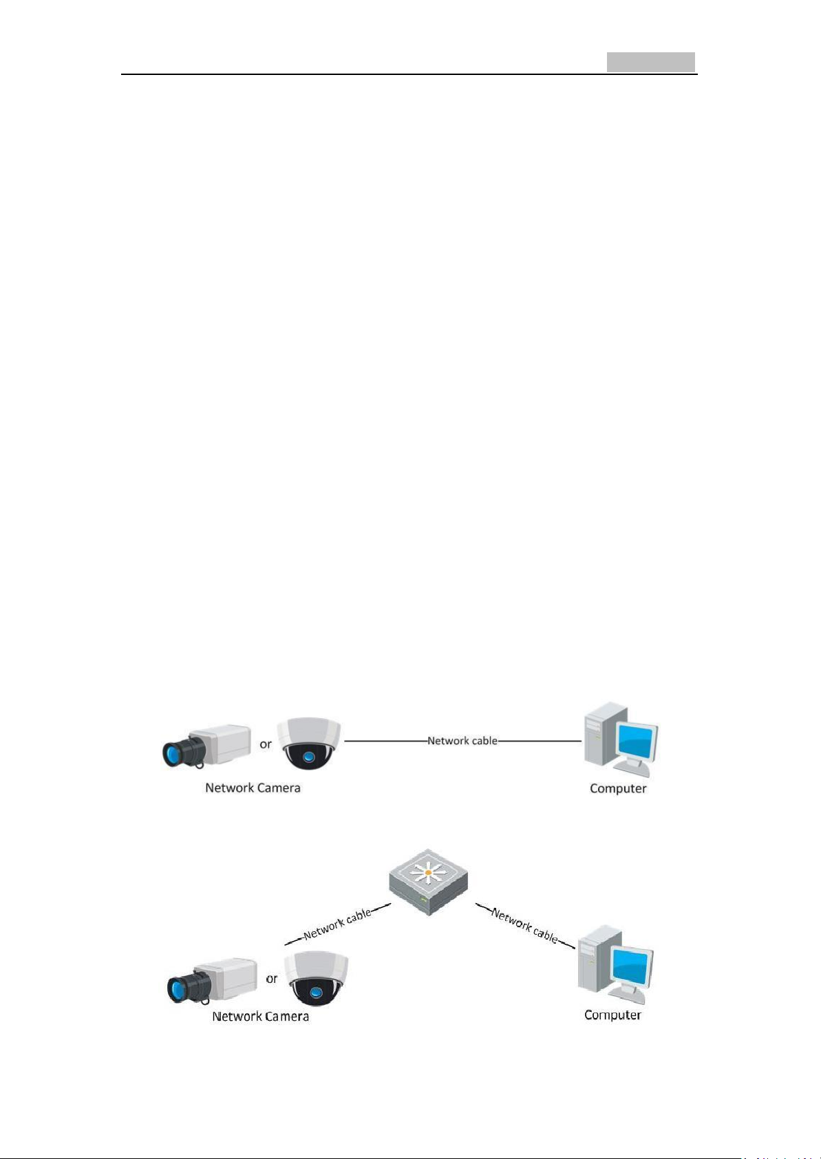
2.1.1 Wiring over the LAN
The following figures show the two ways of cable connection of a network camera
and a computer:
Purpose:
●To test the network camera, you can directly connect the network camera to the
computer with a network cable as shown in Figure 2-1.
●Refer to the Figure 2-2 to set the network camera over the LAN via a switch or a
router.
Figure 2-1 Connecting Directly
Figure 2-2 Connecting via a Switch or a Router
Network Camera User’s Manual
13
2.1.2 Detecting and Changing the IP Address
You need the IP address of the network camera to see it via a web browser.
Steps:
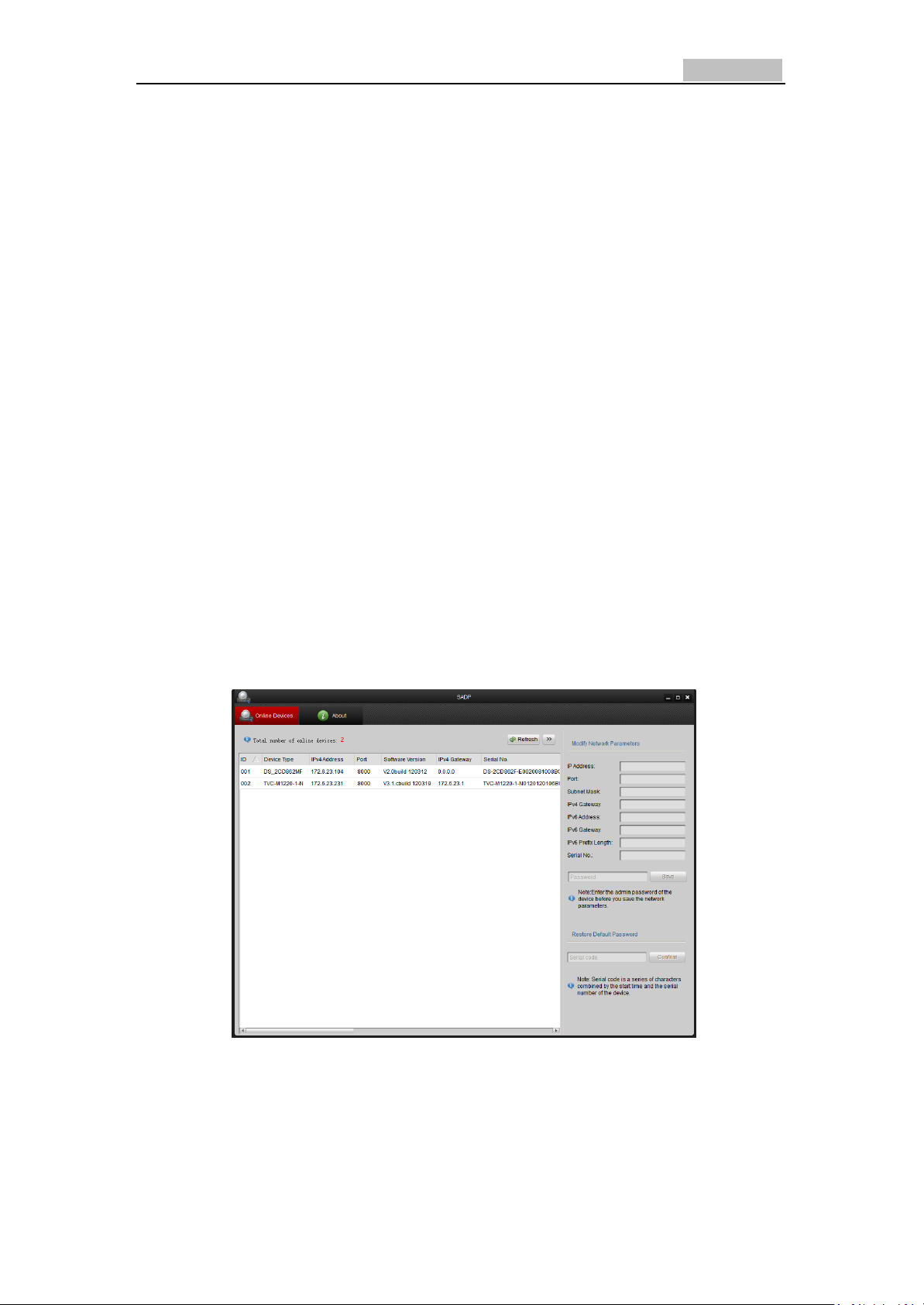
1. To get the IP address, you can choose either of the following methods:
●Use SADP, a software tool which can automatically detect the online network
cameras in the LAN and list the device information including IP address,
subnet mask, port number, device serial number, device version, etc.,
shown in Figure 2-3.
●Use the client software to list the online devices. Please refer to the user
manual of client software for detailed information.
2. Change the IP address and subnet mask to the same subnet as that of your
computer.
3. Enter the IP address of network camera in the address field of the web browser
to view the live video.
Notes:
●The default IP address is 192.0.0.64 and the defau lt port number is 8000. The
default user name is admin, and password is 12345.
●For accessing the network camera from different subnets, please set the gateway for
the network camera after you logged in. For detailed information, please refer
to Section 5.3.1 Configuring TCP/IP Settings.
Figure 2-3 SADP Interface
Network Camera User’s Manual
14
2.2 Setting the Network Camera over the WAN
Purpose:
This section explains how to connect the network camera to the WAN with a static IP
or a dynamic IP.
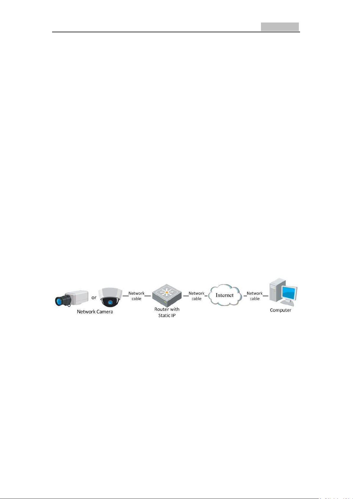
2.2.1 Static IP Connection
Before you start:
Please apply a static IP to the camera. With the static IP address, you can connect
the network camera via a router or connect it to the WAN directly.
●Connecting the network camera via a router
Steps:
1. Connect the network camera to the router.
2. Assign a LAN IP address, the subnet mask and the gateway. Refer to Section 2.1.2
Detecting and Changing the IP Address for detailed IP address configuration of
the camera.
3. Save the static IP in the router.
4. Set port mapping: TCP 80, TCP/UDP 8000 and TCP/UDP 554 ports. The steps for
port mapping vary depending on different routers. Please call the router
manufacturer for assistance with port mapping.
Note: Refer to Appendix 2 for detailed information about port mapping.
5. Visit the network camera through a web browser or the client software over the
internet.
Figure 2-4 Accessing the Camera through Router with Static IP
Network Camera User’s Manual
15
2.2.2 Dynamic IP Connection
Before you start:
Please apply a dynamic IP from an ISP. With the dynamic IP address, you can connect
the network camera to a modem or a router.
●Connecting the network camera via a router
Steps:
1. Connect the network camera to the router.
2. In the camera, assign a LAN IP address, the subset mask and the gateway. Refer
to Section 2.1.2 Detecting and Changing the IP Address for detailed LAN
configuration.
3. In the router, set the Poe user name, password and confirm the password.
4. Set port mapping. The steps for port mapping vary depending on different routers.
Please call the router manufacturer for assistance with port mapping.
Note: Refer to Appendix 2 for detailed information about port mapping.
5. Apply a domain name from a domain name provider.
6. Configure the DDNS settings in the setting interface of the router.
7. Visit the camera via the applied domain name.
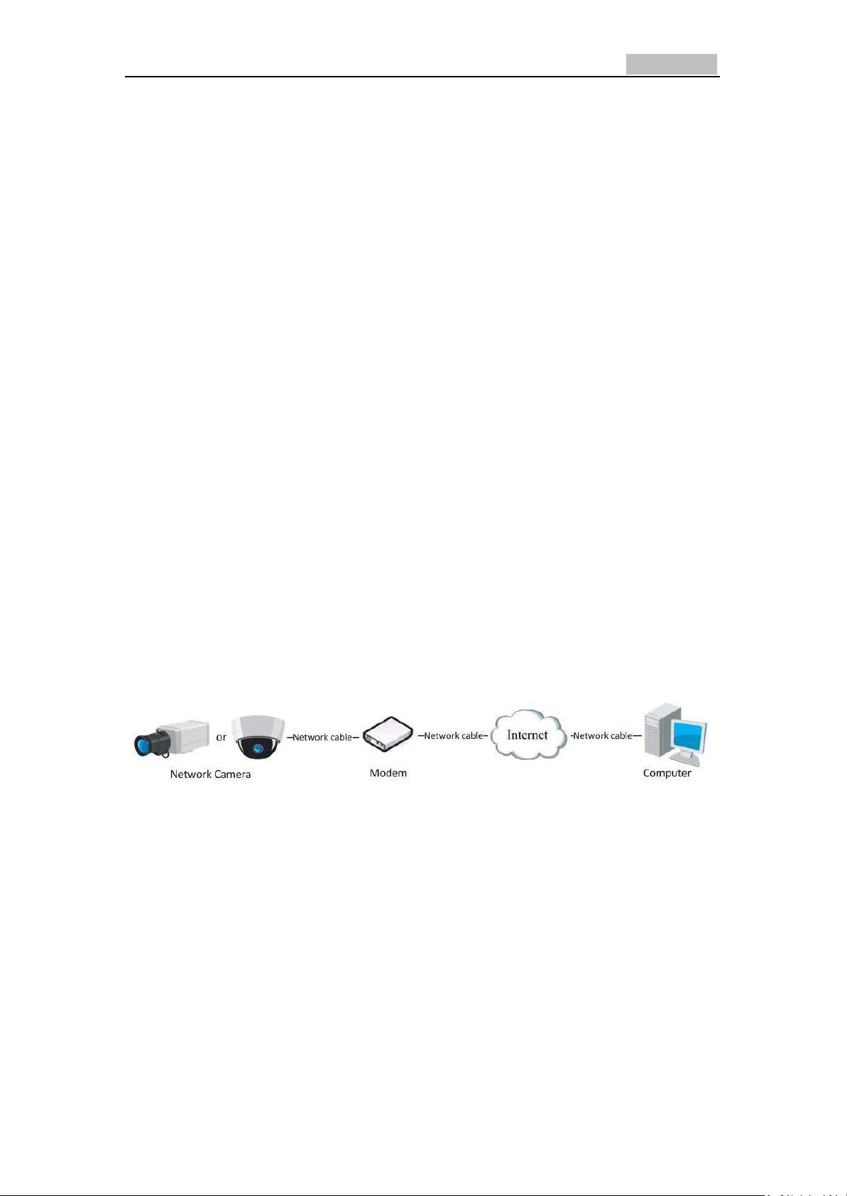
●Connecting the network camera via a modem
Purpose:
This camera supports the PPPoE auto dial-up function. The camera gets a public IP
address by ADSL dial-up after the camera is connected to a modem. You need to
configure the PPPoE parameters of the network camera. Refer to Section 5.3.3
Configuring PPPoE Settings for detailed configuration.
Figure 2-6 Accessing the Camera with Dynamic IP
Note: The obtained IP address is dynamically assigned via PPPoE, so the IP address
always changes after rebooting the camera. To solve the inconvenience of the
dynamic IP, you need to get a domain name from the DDNS provider (Example:
DynDns.com). Please follow below steps for normal domain name resolution and
private domain name resolution to solve the problem.
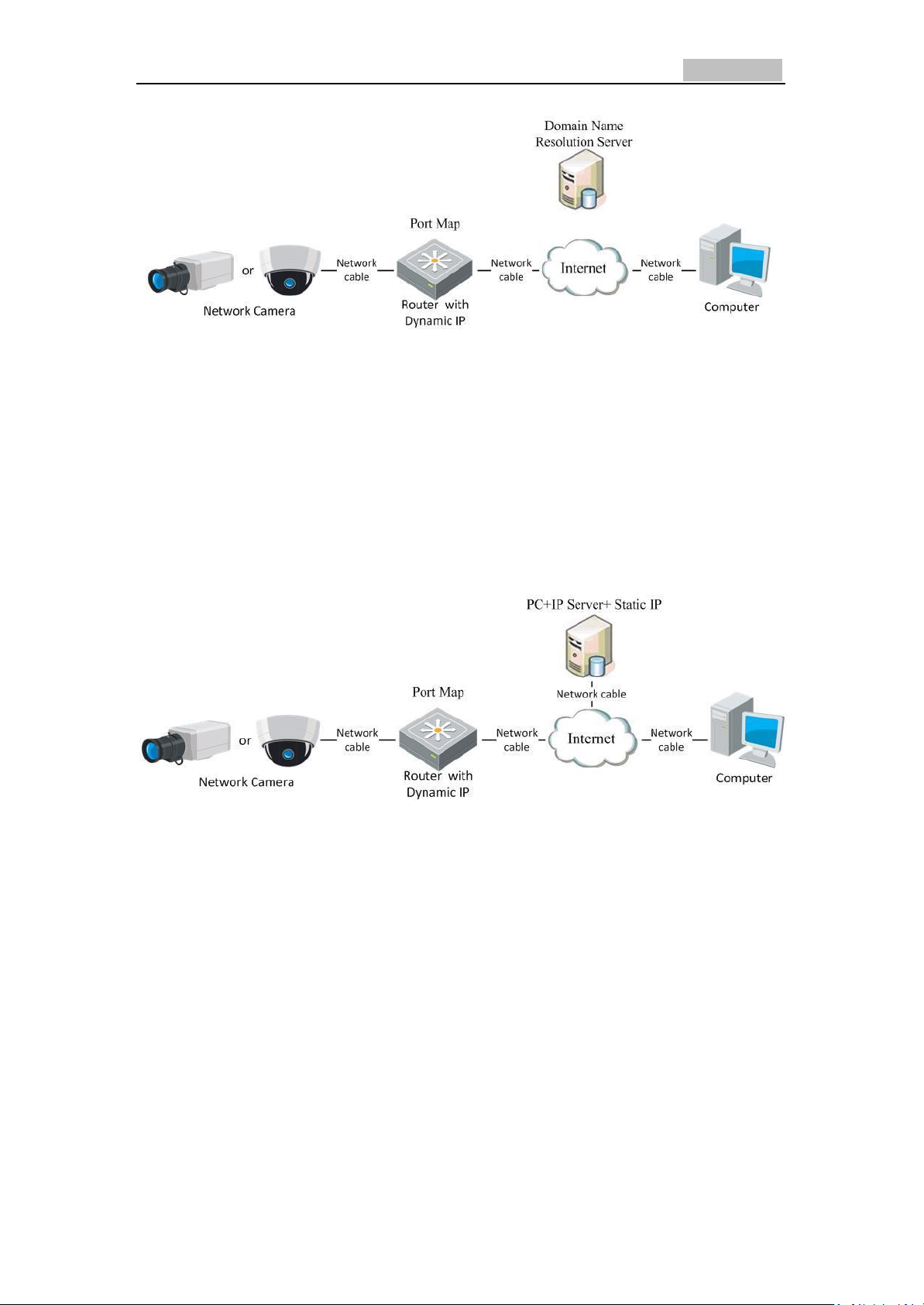
●Normal Domain Name Resolution
Network Camera User’s Manual
16
Steps:
Figure 2-7 Normal Domain Name Resolution
Figure 2-7 Normal Domain Name Resolution
1. Apply a domain name from a domain name provider.
2. Configure the DDNS settings in the DDNS Settings interface of the network camera.
Refer to Section 5.3.4 Configuring DDNS Settings for detailed configuration.
3. Visit the camera via the applied domain name.
●Private Domain Name Resolution
Steps:
Figure 2-8 Private Domain Name Resolution
Figure 2-8 Private Domain Name Resolution
1. Install and run the IP Server software in a computer with a static IP.
2. Access the network camera through the LAN with a web browser or the client
software.
3. Enable DDNS and select IP Server as the protocol type. Refer to Section 5.3.4
Configuring DDNS Settings for detailed configuration.
Network Camera User’s Manual
17
Chapter 3 Access to the Network
Camera
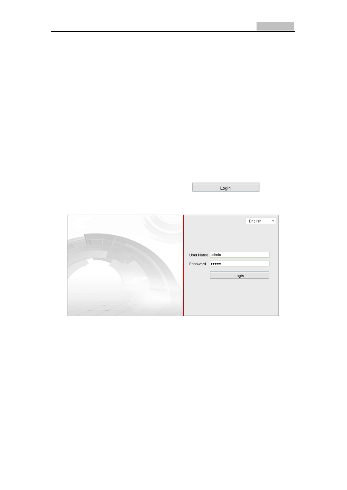
3.1 Accessing by Web Browsers
Steps:
1. Open the web browser.
2. In the address field, input the IP address of the network camera (Example:
192.0.0.64) and press the Enter key to enter the login interface.
3. Input the user name and password and click .
Note: The default user name is admin, password is 12345.
Figure 3-1 Login Interface
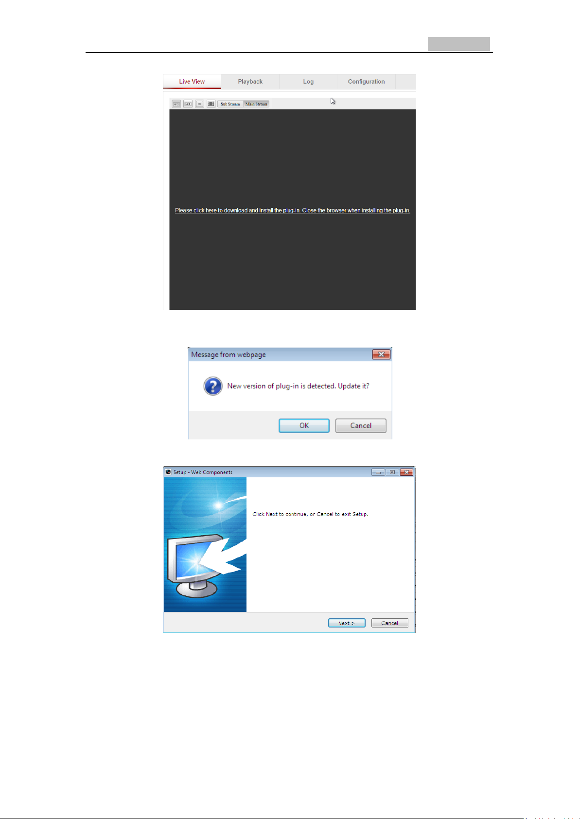
4. Install the plug-in before viewing the live video and operating the camera. Please
follow the installation prompts to install the plug-in.
Network Camera User’s Manual
18
Figure 3-2 Download and Install Plug-in
Figure 3-3 Install Plug-in (1)
Figure 3-4 Install Plug-in (2)
Network Camera User’s Manual
19
Figure 3-5 Install Plug-in (3)
Note: You may have to close the web browser to install the plug-in. Please reopen
the web browser and log in again after installing the plug-in.
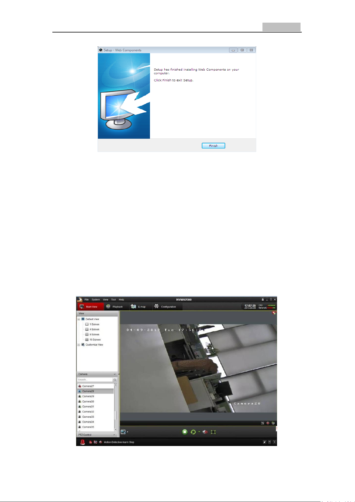
3.2 Accessing by Client Software
3.2.1 Accessing by VMS Client Software
The product CD contains the VMS Client Software (Client or PCNVR). You can view
the live video and manage the camera with the client software.
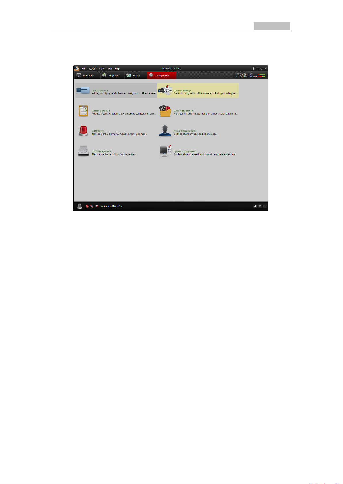
Follow the installation prompts to install the software. The control panel and live
view interface of VMS Client Software are shown as bellow.
Network Camera User’s Manual
20
Figure 3-6 VMS CLIENT SOFTWARE Live View
Figure 3-7 VMS CLIENT SOFTWARE
Configuration Panel
Note: For detailed information about VMS Client software, please refer to the user
manual of the VMS CLIENT SOFTWARE software.
Network Camera User’s Manual
21
Chapter 4 Configuring the Wi-Fi
Settings
Purpose:
By connecting to the wireless network, you don’t need to use cable of any kind for
network connection, which is very convenient for the actual surveillance application.
Note:
This chapter is only applicable for the cameras with the Wi-Fi module built-in.
4.1 Configuring Wi-Fi Connection in Manage and
Ad-hoc Modes
Before you start:
A wireless network must be configured.
Wireless Connection in Managed Mode
Steps:
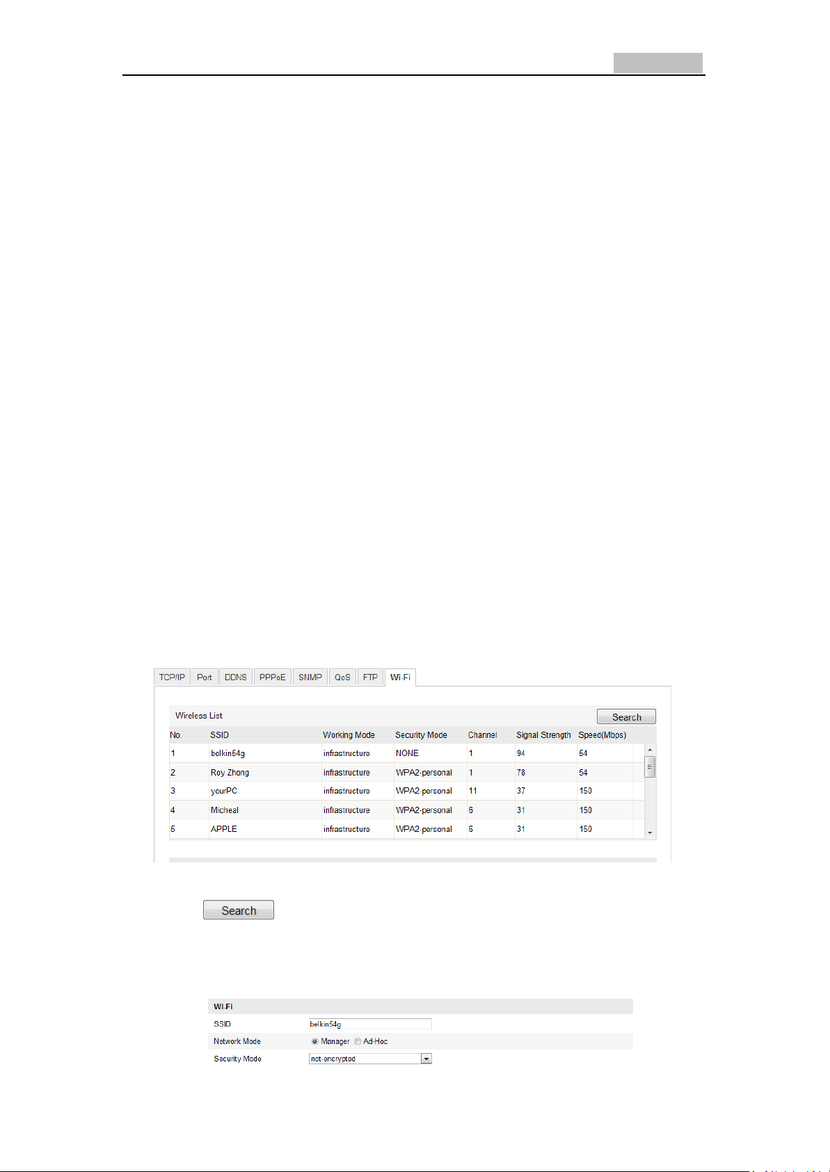
1. Enter the Wi-Fi configuration interface.
Configuration> Advanced Configuration> Network> Wi-Fi
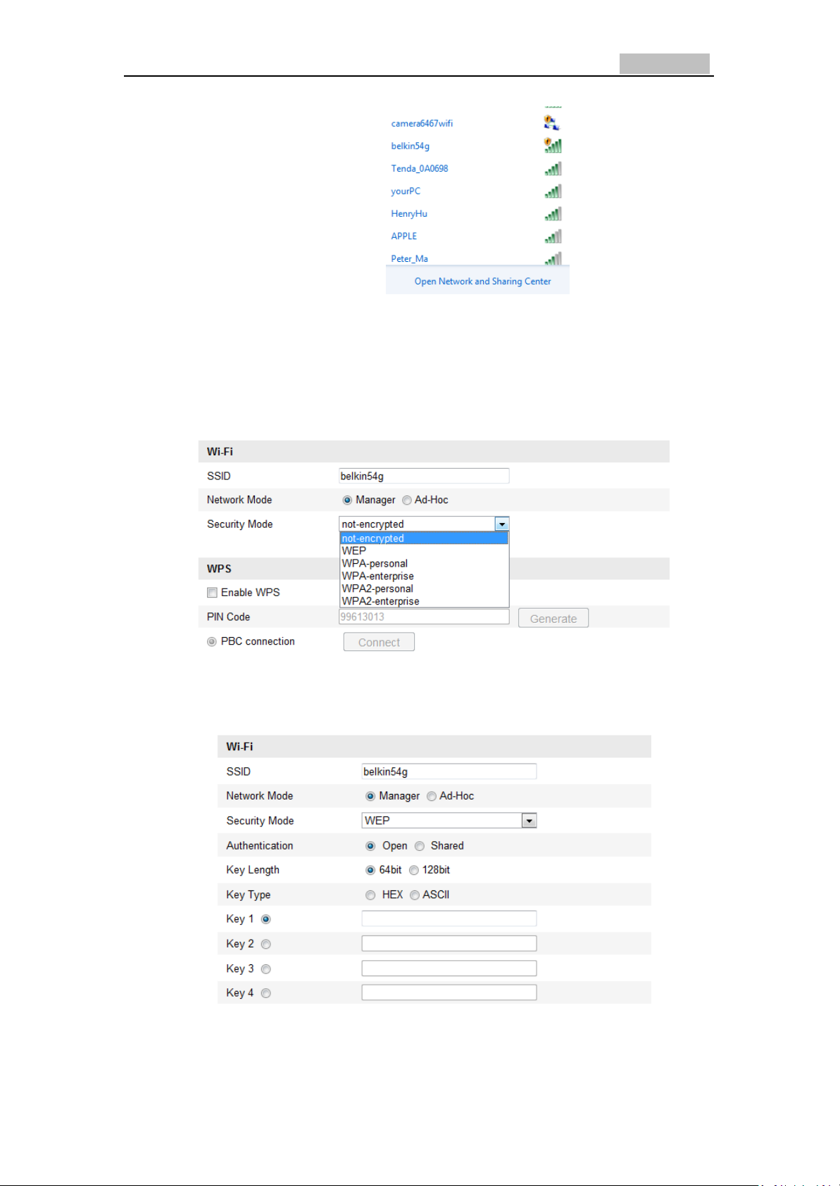
Figure 4-1 Wireless Network List
2. Click button to search the online wireless connections.
3. Click to choose a wireless connection on the list.
Figure 4-2 Wi-Fi Setting- Managed Mode
Network Camera User’s Manual
22
4. Check the check box to select the Network Mode as Managed, and the
Security mode and the Encryption Type of the network is automatically shown
when you select the wireless network, please don’t change it manually.
Note: These parameters are exactly identical with those of the router.
5. Enter the key to connect the wireless network. The key should be that of the
wireless network connection you set on the router.
Wireless Connection in Ad-hoc Mode
If you choose the Ad-hoc mode, you don’t need to connect the wireless camera
via a router. The scenario is the same as you connect the camera and the PC directly
with a network cable.
Steps:
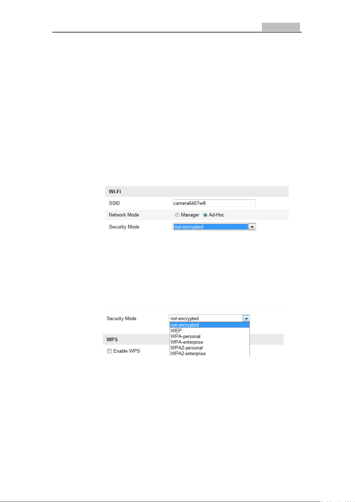
1. Choose Ad-hoc mode.
Figure 4-3 Wi-Fi Setting- Ad-hoc
2. Customize a SSID for the camera.
3. Choose the Security Mode of the wireless connection.
Figure 4-4
Figure 4-5 Security Mode- Ad-hoc Mode
4. Enable the wireless connection function for your PC.
5. On the PC side, search the network and you can see the SSID of the
camera listed.
Network Camera User’s Manual
23
Figure 4-6 Ad-hoc Connection Point
6. Choose the SSID and connect.
Security Mode Description:
You can choose the Security Mode as not-encrypted, WEP, WPA-personal, WPA-
enterprise, WPA2-personal, WPA2-enterprise.
WEP mode:
●Authentication - Select Open or Shared Key System Authentication, depending on
the method used by your access point. Not all access points have this option, in
which case they probably use Open System, which is sometimes known as SSID
Network Camera User’s Manual
24
Authentication.
●Key length - This sets the length of the key used for the wireless encryption, 64 or
128 bit. The encryption key length can sometimes be shown as 40/64 and
104/128.
●Key type - The key types available depend on the access point being used. The
following options are available:
HEX - Allows you to manually enter the hex key.
ASCII - In this method the string must be exactly 5 characters for 64-bit WEP
and 13 characters for 128-bit WEP.
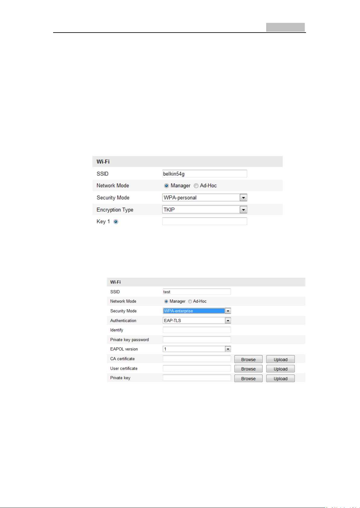
WPA-personal and WPA2-personal Mode:
Enter the required Pre-shared Key for the access point, which can be a hexadecimal
number or a pass phrase.
WPA- enterprise and WPA2-enterprise Mode:
Choose the type of client/server authentication being used by the access point; EAP-
TLS or EAP-PEAP.
EAP-TLS
●Identity - Enter the user ID to present to the network.
●Private key password – Enter the password for your user ID.
●EAPOL version - Select the version used (1 or 2) in your access point.
●CA Certificates - Upload a CA certificate to present to the access point for
authentication.
EAP-PEAP:
Network Camera User’s Manual
25
●User Name - Enter the user name to present to the network
●Password - Enter the password of the network
●PEAP Version - Select the PEAP version used at the access point.
●Label - Select the label used by the access point.
●EAPOL version - Select version (1 or 2) depending on the version used at the
access point
●CA Certificates - Upload a CA certificate to present to the access point for
authentication
4.2 Easy Wi-Fi Connection with WPS function
Purpose:
The setting of the wireless network connection is never easy. To avoid the
complex setting of the wireless connection you can enable the WPS function.
WPS (Wi-Fi Protected Setup) refers to the easy configuration of the encrypted
connection between the device and the wireless router. The WPS makes it easy to
add new devices to an existing network without entering long pass phrases. There are
two modes of the WPS connection, the PBC mode and the PIN mode.
Note: If you enable the WPS function, you don’t need to configure the parameters
such as the encryption type and you don’t need to know the key of the wireless
connection.
Steps:
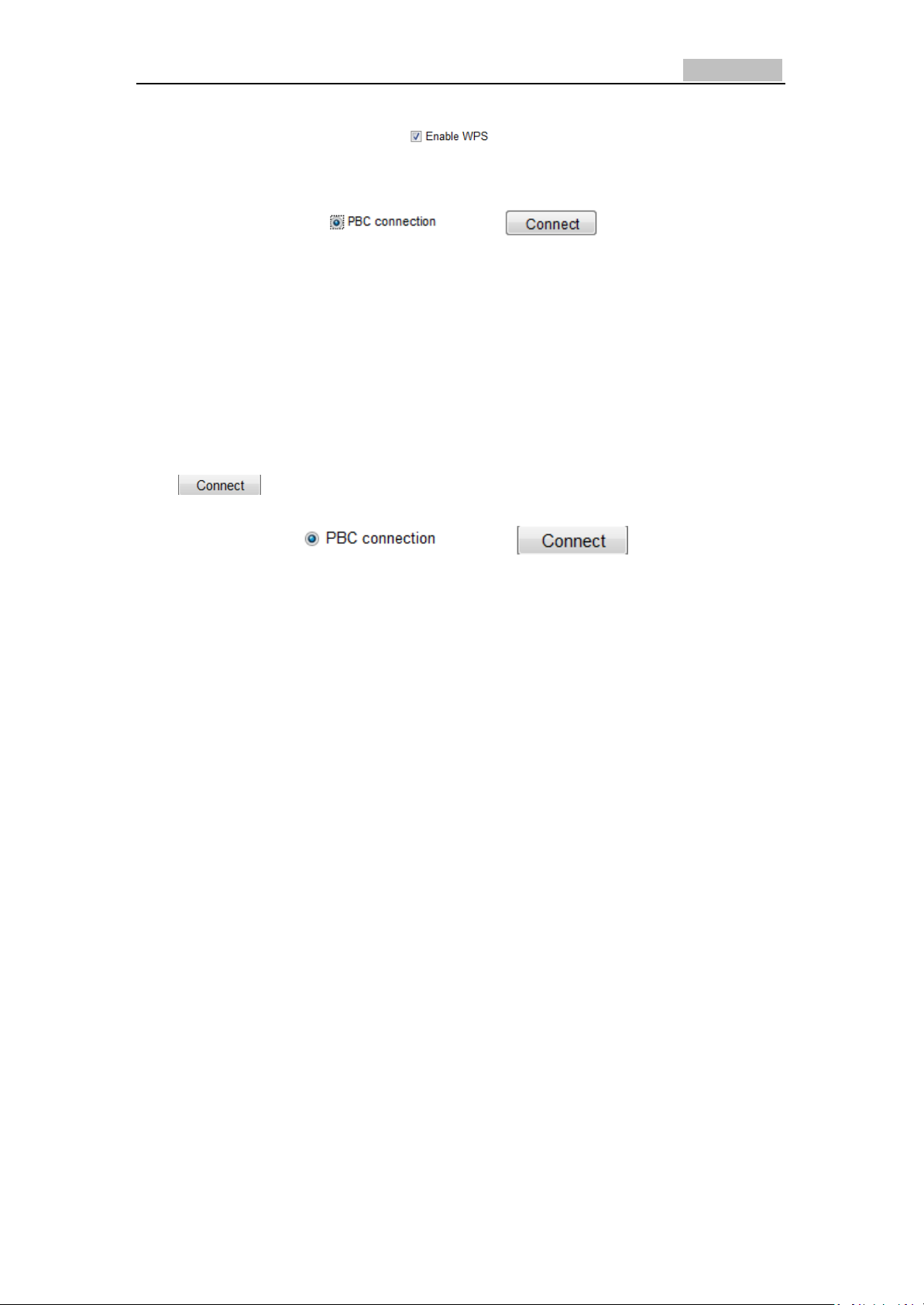
PBC Mode:
Figure 4-7 Wi-Fi Settings - WPS
Figure 4-7 Wi-Fi Settings - WPS
PBC refers to the Push-Button-Configuration, in which the user simply has to
push a button, either an actual or virtual one (as the button on the
configuration interface of the IE browser), on both the Access Point (and a registrar
of the network) and the new wireless client device.
Network Camera User’s Manual
26
1. Check the check box of to enable WPS.
2. Choose the connection mode as PBC.
Note: Support of this mode is mandatory for both the Access Points and the
connecting devices.
3. Check on the Wi-Fi router to see if there is a WPS button. If yes push the
button and you can see the indicator near the button start flashing, which
means the WPS function of the router is enabled. For detailed operation,
please see the user guide of the router.
4. Push the WPS button to enable the function on the camera.
If there is not a WPS button on the camera, you can also click the virtual button to
enable the PBC function on the web interface.
Click button.
When the PBC mode is both enabled in the router and the camera, the camera and
the wireless network is connected automatically.
PIN Mode:
The PIN mode requires a Personal Identification Number (PIN) to be read from either
a sticker or the display on the new wireless device. This PIN must then be entered to
connect the network, usually the Access Point of the network.
Steps:
1. Choose a wireless connection on the list and the SSID is shown.
Network Camera User’s Manual
27
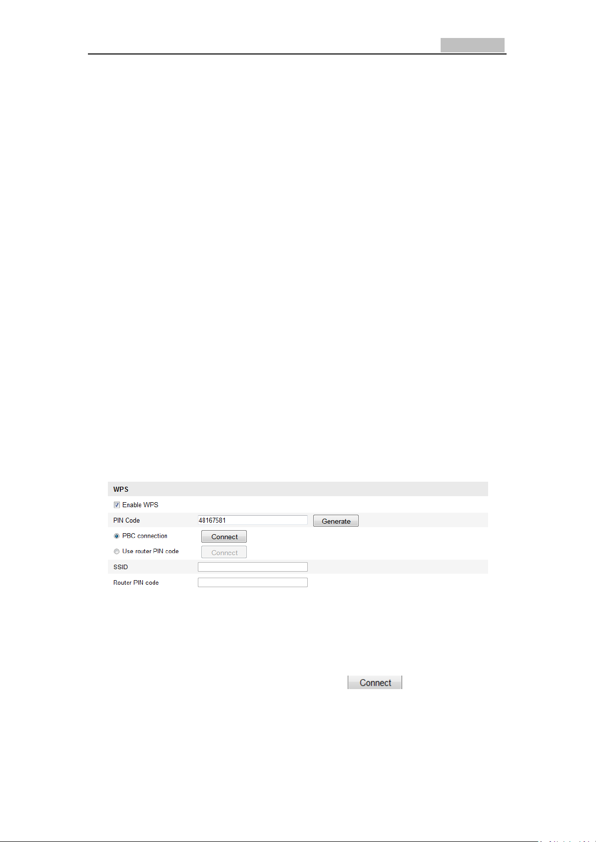
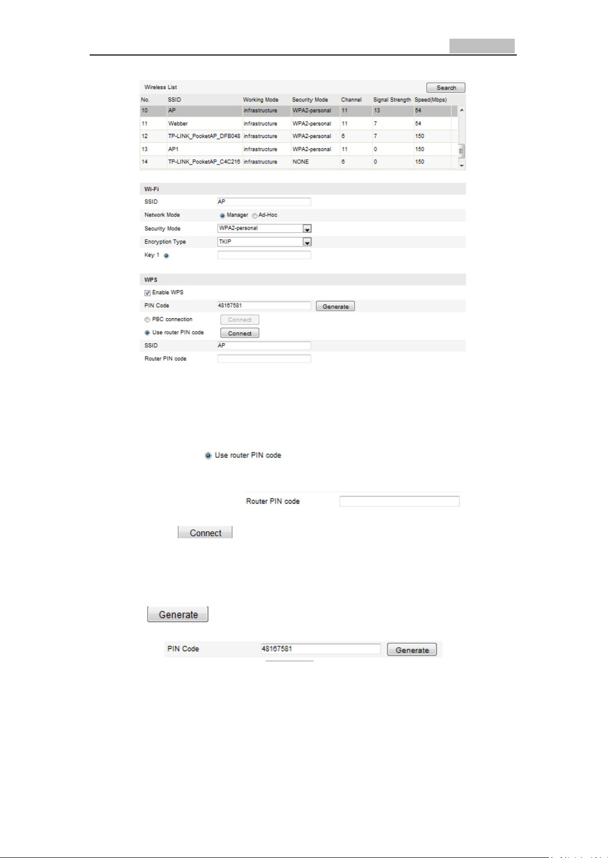
Figure 4-8 Wi-Fi Settings – WPS PIN Mode
2. Choose the .
If the PIN code is generated from the router side, you should enter the PIN code you
get from the router side in the field.
3. Click button.
Or
You can generate the PIN code on the camera side. And the expired time for the PIN
code is 120 seconds.
1. Click
2. Enter the code to the router, in the example, enter 48167581 to the router.
 Loading...