

Page 1

911
CNC-controlled sewing unit with large
sewing area
Operating Instructions
Installation Instructions
Service Instructions
1
2
3
Postfach 17 03 51, D-33703 Bielefeld Potsdamer Straße 190, D-33719 Bielefeld
Telefon +49 (0) 5 21/ 59 25-00 Telefax +49 (0) 5 21/ 9 25 24 35 www.duerkopp-adler.com
Ausgabe / Edition: Änderungsindex Teile-Nr./Part.-No.:
08/2010 Rev. index: 00.0 Printed in Federal Republic of Germany 0791 911001
Page 2

All rights reser ved.
Property of Dürkopp Adler AG and copyrighted. Reproduction or publication of the content in any
manner, even in extracts, without prior written permission of Dürkopp Adler AG, is prohibited.
Copyright ©
Dürkopp Adler AG - 2010
Page 3

Foreword
This instruction manual is intended to help the user to become familiar
with the machine and take advantage of its application possibilities in
accordance with the recommendations.
The instruction manual contains important information on how to
operate the machine securely, properly and economically. Observation
of the instructions eliminates danger, reduces costs for repair and
down-times, and increases the reliability and life of the machine.
The instruction manual is intended to complement existing national
accident prevention and environment protection regulations.
The instruction manual must always be available at the machine/sewing
unit.
The instruction manual must be read and applied by any person that is
authorized to work on the machine/sewing unit. This means:
– Operation, including equipping, troubleshooting during the work
cycle, removing of fabric waste,
– Service (maintenance, inspection, repair) and/or
– Transport.
The user also has to assure that only authorized personnel work on the
machine.
The user is obliged to check the machine at least once per shift for
apparent damages and to immediatly report any changes (including the
performance in service), which impair the safety.
The user company must ensure that the machine is only operated in
perfect working order.
Never remove or disable any safety devices.
If safety devices need to be removed for equipping, repairing or
maintaining, the safety devices must be remounted directly after
completion of the maintenance and repair work.
Unauthorized modification of the machine rules out liability of the
manufacturer for damage resulting from this.
Observe all safety and danger recommendations on the machine/unit!
The yellow-and-black striped surfaces designate permanend danger
areas, eg danger of squashing, cutting, shearing or collision.
Besides the recommendations in this instruction manual also observe
the general safety and accident prevention regulations!
Page 4

General safety instructions
The non-observance of the following safety instructions can cause
bodily injuries or damages to the machine.
1. The machine must only be commissioned in full knowledge of the
2. Before putting into service also read the safety rules and
3. The machine must be used only for the purpose intended. Use of
4. When gauge parts are exchanged (e.g. needle, presser foot, needle
5. Daily servicing work must be carried out only by appropriately
instruction book and operated by persons with appropriate training.
instructions of the motor supplier.
the machine without the safety devices is not permitted. Observe all
the relevant safety regulations.
plate, feed dog and bobbin) when threading, when the workplace is
left, and during service work, the machine must be disconnected
from the mains by switching off the master switch or disconnecting
the mains plug.
trained persons.
6. Repairs, conversion and special maintenance work must only be
carried out by technicians or persons with appropriate training.
7. For service or repair work on pneumatic systems, disconnect the
machine from the compressed air supply system (max. 7-10 bar).
Before disconnecting, reduce the pressure of the maintenance unit.
Exceptions to this are only adjustments and functions checks made
by appropriately trained technicians.
8. Work on the electrical equipment must be carried out only by
electricians or appropriately trained persons.
9. Work on parts and systems under electric current is not permitted,
except as specified in regulations DIN VDE 0105.
10. Conversion or changes to the machine must be authorized by us
and made only in adherence to all safety regulations.
11. For repairs, only replacement parts approved by us must be used.
12. Commissioning of the sewing head is prohibited until such time as
the entire sewing unit is found to comply with EC directives.
13. The line cord should be equipped with a country-specific mains
plug. This work must be carried out by appropriately trained
technicians (see paragraph 8).
It is absolutely necessary to respect the safety
instructions marked by these signs.
Danger of bodily injuries !
Please note also the general safety instructions.
Page 5

Contents Page:
Preface and General Safety Instructions
Part 1: Operating Instructions Cl. 911 - Original Instructions
(Edition 08/2010)
1 Product Description ..............................................3
2 Designated Use .................................................5
3 Subclasses ....................................................5
4 Optional Equipment ...............................................6
1
5 Technical Data ..................................................7
6 Operation
6.1 Switchingon-Switchingoff-Safestop-Quickstop...........................8
6.2 Raisingthemachinehead...........................................11
6.3 Changingtheneedle..............................................12
6.4 Threadingtheneedlethread .........................................13
6.5 Adjustingthethreadregulator ........................................14
6.6 Winding on the hook thread ..........................................15
6.7 Changing the hook-thread bobbin ......................................16
6.8 Setting the hook thread tension .......................................17
7 Operating the control unit of the 911
7.1 Thecontrolpanel................................................18
7.2 Operatingthetouchscreenpanel......................................18
7.3 Thestartscreen.................................................22
7.4 Themainscreen.................................................23
7.5 Popupmenustructure.............................................24
7.6 Menuitem“File”.................................................25
7.7 Menuitem“Edit” ................................................29
7.8 Menuitem“Extras”...............................................41
7.9 Menuitem“Correction” ............................................49
7.10 Menuitem“?”..................................................50
7.11 Teach-in ......................................................51
7.12 Repairmode...................................................55
7.13 Thread breakage ................................................56
8 DA-CAD 5000 ..................................................57
Page 6

Contents Page:
9 Error messages/Information messages
9.1 Errormessages.................................................59
9.2 Informationmessages.............................................63
10 Maintenance
10.1 Cleaning and Checking ............................................64
10.2 OilLubrication..................................................65
Page 7

1 Product Description
CNC-controlled sewing unit based on the class 867 with large sewing
area (sewing field size 300 x 200 mm) and a DAC III control unit with
special software.
For technical textiles manufacturers, motor vehicle equipment
manufacturers, seat manufacturers (automotive), bag, case and
backpack manufacturers (leather/textile), shoe manufacturers.
For the following applications:
Bartacks on load-bearing straps, lowering harnesses, safety
harnesses, lashing straps; Attaching of labels and facing pieces;
Decorative seams on shoes and legs of boots, decorative seams in
special applications.
Material:
Straps, ropes, leather, webbing, airbag materials, leather cut, foam
laminate, leather- laminate- and textile plastics
Double-lockstitch machine equipped with:
Automatic sewing foot and clamp lifting, sewing stroke adjustment,
thread trimmer, needle thread monitoring, thread pulling device and
multiple thread tension.
1
Technical specifications
The sewing unit is driven by a positioning drive.
With the control unit DACIII are operated apart from the sewing drive
also two step motors needed for the X and Y motions of the seam
geometry and a Z axis for the adjustment of the sewing foot.
The arm shaft of the sewing unit is directly driven by a brushless DC
motor.
Max. speed 3,000 U/min.
·
Stitch length up to 12.7 mm.
·
99 program memory locations are available.
·
The programs can be sewn individually or in sequences.
·
Motor driven sewing foot lifting.
·
Pneumatic driven clamp opening/closing.
·
The maximum size of the sewing field is 300 mm in X direction and
·
200 mm in Y direction.
Central oil wick lubricating for the machine head and the hook.
·
Equipped with a vertical hook
·
The BFT graphical control panel OP 7000 serves as control
·
element.
3
Page 8

With electronic needle thread monitor.
In order to generate a clean seam pattern, the sewing unit is equipped
with a multiple thread tension device, permitting to assign to various
thread pulling directions the according tension value previously saved
in the sewing program.
The thread pulling device allows pulling the needle thread under the
sewing material during the first stitch.
The sewing unit is equipped with a programmable stitch counter for
the hook thread monitoring and a piece counter.
Integrated test and check program for service and maintenance
works. In addition to the monitoring of the sewing process, it is also
possible to check the motor functions, the inputs and outputs for the
reference switches, the v alves and the feeding motors. The program
also serves for the adjustment of machine functions and the preparing
of sewing programs by the teach-in method.
Individual stitch parameter per stitch in order to control external units
like:
The stroke position of the presser foot, thread trimmer, thread
·
clamp,
Speed, thread tension etc.
·
The height of the stand can be adjusted with the telescoping feet from
a minimum work height of 760 mm to a maximum work height of 910
mm for stand-up working.
The foot pedal needed to operate the sewing unit can be shifted to
allow an ergonomic adaption to the operator.
4
Page 9

2 Designated Use
The class 911 is a sewing unit that is designated for the sewing of
light to medium-heavy material. Such material is generally made of
textile fibers, composite materials but it may also consist of leather.
Suchlike material is used in the clothing industry and for domestic and
motor-vehicle upholstery.
This sewing unit can also be used to produce so-called technical
seams. In this case however, the operator must assess the possible
dangers which may arise (DÜRKOPP ADLER AG will be happy to offer
its assistance), since such applications are relatively rare and at the
same time can be so varied that no single set of criteria can cover
them all. The outcome of this assessment may require appropriate
safety measures to be taken.
Generally only dry material may be sewn with this sewing unit. The
material may be no thicker than 4 mm when compressed by the
lowered workclamp. The material may not contain any hard objects.
The seam is generally produced with textile-fibre s ewing thread
(cotton threads, synthetic yarns of covering yarns) with the following
dimensions:
Class 911 thread thickness 15/3 - 120/3
Before using any other thread the possible dangers arising have to be
assessed and appropriate safety measures if necessary taken.
This sewing unit may be set up and operated only in dry,
well-maintained premises. If the sewing unit is used in
premises which are not dry and well-maintained it may be
necessary to take further precautions which should be agreed in
advance (see EN 60204-31:1999).
As manufacturers of industrial sewing machines we proceed on the
assumption that personnel who work on our products will have
received training at least sufficient to acquaint them with all normal
operations and with any hazards which these may involve.
1
3 Subclasses
Cl. 911-210 CNC-controlled sewing unit based on the class 867 with large sewing
area (sewing field size 300 x 200 mm) and a DAC III control unit with
special software.
5
Page 10

4 Optional Equipment
For the sewing unit 911 the following optional equipment is available:
Optional equipment Order-No. Remark
Reception P.-Clamp 0911 457554 Kit for the reception of the parallel
clamp actuation
Bow f. P.- Clamp 0911 457604 Bow holding fixture for the clamping plate
P.-set of clamps HF 0911 417604 parallel set of clamps HF (bow bracket)
P.-set of clamps prg.1 0911 417634 Finished set of clamps f. parallel
clamp act. prg.1
P.-set of clamps prg.2 0911 417644 Finished set of clamps f. parallel
clamp act. prg.2
P.-set of clamps prg.3 0911 417654 Finished set of clamps f. parallel
clamp act. prg.3
L-bracket f. P.-Clamp 0911 457614 Kit L-bracket for reception of the divided
clamp (parallel)
P.-set of clamps HF div. 0911 417614 P.-set of clamps HF, divided, fastening with L-bracket
P.-set of clamps div. prg.1 0911 417664 Finished P.-set of clamps for divided clamp pgr.1
P.-set of clamps div. prg.2 0911 417674 Finished P.-set of clamps for divided clamp pgr.2
P.-set of clamps div. prg.3 0911 417684 Finished P.-set of clamps for divided clamp pgr.3
P.-set of clamps HF div. 0911 417624 P.-set of clamps HF, divided, fastening w. L-bracket
closed frame
P.-set of clamps div. prg.1 0911 417694 Finished P.-set of clamps, div., with
closed frame prg.1
P.-set of clamps div. prg.2 0911 417704 Finished P.-set of clamps, div., with
closed frame prg.2
P.-set of clamps div. prg.3 0911 417714 Finished P.-set of clamps, div., with
closed frame prg.3
Reception f. change-over clamp 0911 457564 Kit for the reception of the change-over clamp
C.-set of clamps HF 0911 417524 Change-over s et of clamps HF
C.-set of clamps prg.1 0911 417554 Finished change-over set of clamps prg.1
C.-set of clamps prg.2 0911 417564 Finished change-over set of clamps prg.2
C.-set of clamps prg.3 0911 417574 Finished change-over set of clamps prg.3
Kit reduced pressure 0911 597544
Kit barcode reader 0911 597554
Set throat plate 0911 597504 Throat plate for processing thin materials
Set presser foot 0911 597514 Presser foot
Jumping foot 0467 220283 For thin material
Sewing lamp complete 9822 510026
Table clamp 9822 510027
Pneumatic connection package 0797 003031
Height adjustment 0911 407524 Table top height adjustable from 800mm to 1050mm
6
Page 11

5 Technical Data
Type of stitch 301
Hook type Vertical hook
Needle system 134/35
Needle size [Nm] 80 until 180
Number of needles 1
Stitch length (programmable) [mm] depending on the seam pattern up to 12.7
max. speed [min
Clamp stroke [mm] 20
Foot lifting [mm] 20
Sewing field size [mm] 300 x 200
Number of free contour programs 99
Operating pressure [bar] 6
Air consumption [NL] 4
-1
] max. 3000 1/min
Table height (adjustable
manually via spindle)
-min [mm] 760
-max [mm] 910
Length, Width, Height [mm] 1200 x 1200 x 1150 (+120mm spindle length)
Weight (mounted) [kg] 225
Rated voltage [V] 230
Frequency [Hz] 50 / 60
Rated load [W] 450
Noise:
Lc = dB (A)
Workplace-related emission value in accordance with DIN 45635-48-A-1-KL-2
Sewing length: __ mm
Stitch: __
Speed: _____ min
-1
1
Material: G1 DIN 23328 2 plies
Sewing cycle: 1.3 sec. on and 1.0 sec. off
7
Page 12

6 Operation
6.1 Switching on - Switching off - Safe stop - Quick stop
6.1.1 Switching on
6.1.2 Switching off
1
–
Turn on the main switch 1.
The following request occurs on the display:
“Push Pedal backwards for referencing”
–
Step the pedal backwards to start the reference r un of the sewing
unit.
The main menu appears in the display.
–
Turn off the main switch 1.
All the drives and the control unit are immediately separated from
the mains.
8
Page 13
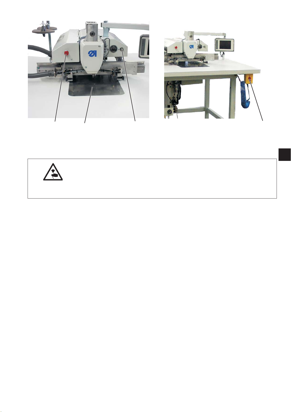
43 2
6.1.3 Safe Stop
Caution: Risk of injury!
The sewing unit has to be switched off or switched to “safe stop”
before carrying out any work on it.
Only work in the hook area with “safe stop” activated when it is
illuminated.
Switching on “safe stop”
–
Press key 2.
The key must snap in!
The sewing unit is in “safe stop” mode.
The lamp in the key shines.
The foot is moved to the lower position.
The area surrounding the hook cover 3 will be illuminated.
Switching off “safe stop”
–
Press key 2 again.
The key must be released.
1
1
6.1.4 Quick stop
The safety system of the sewing unit provokes the immediate stopping
of the unit in case of faulty operation, needle breakage etc. w ith the
following options:
Press the program-stop switch 4.
·
The running operations on the sewing unit will immediately be
aborted.
Turn the main switch 1 counter-clockwise.
·
The sewing unit will immediately be dead.
9
Page 14
1
3
2
10
4
Page 15

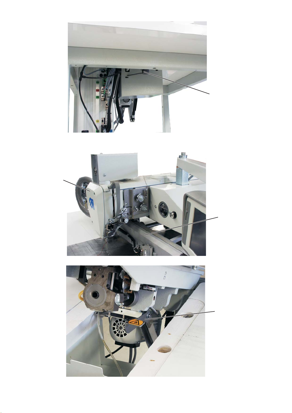
6.2 Raising the machine head
The sewing head can be raised for maintenance work.
The carriage drive 2 must stand at the rear.
Caution: Risk of injury!
Turn the main switch off!
Maintenance may only be carried out with the sewing unit switched
off!
Raising the sewing head
–
Release the locking lever 1 underneath the table top.
–
Raise the machine head in the area of the face cover 3 and swing
it up carefully.
Additionally, the latch 4 will also snap in.
The space under the machine table can be accessed for cleaning
now.
Caution: Risk of injury!
Keep clear of the area within the table top cutout when the machine
head is tilted up.
1
Swinging the machine head back
–
Keep hold of the machine head in the area of the face cover 3.
–
Release the latch 4.
–
Swing the machine head back carefully.
ATTENTION: Danger of breakage!
Keep hold of the sewing head until it has reached its final position.
–
Engage the locking lever 1 under neath the table top.
11
Page 16
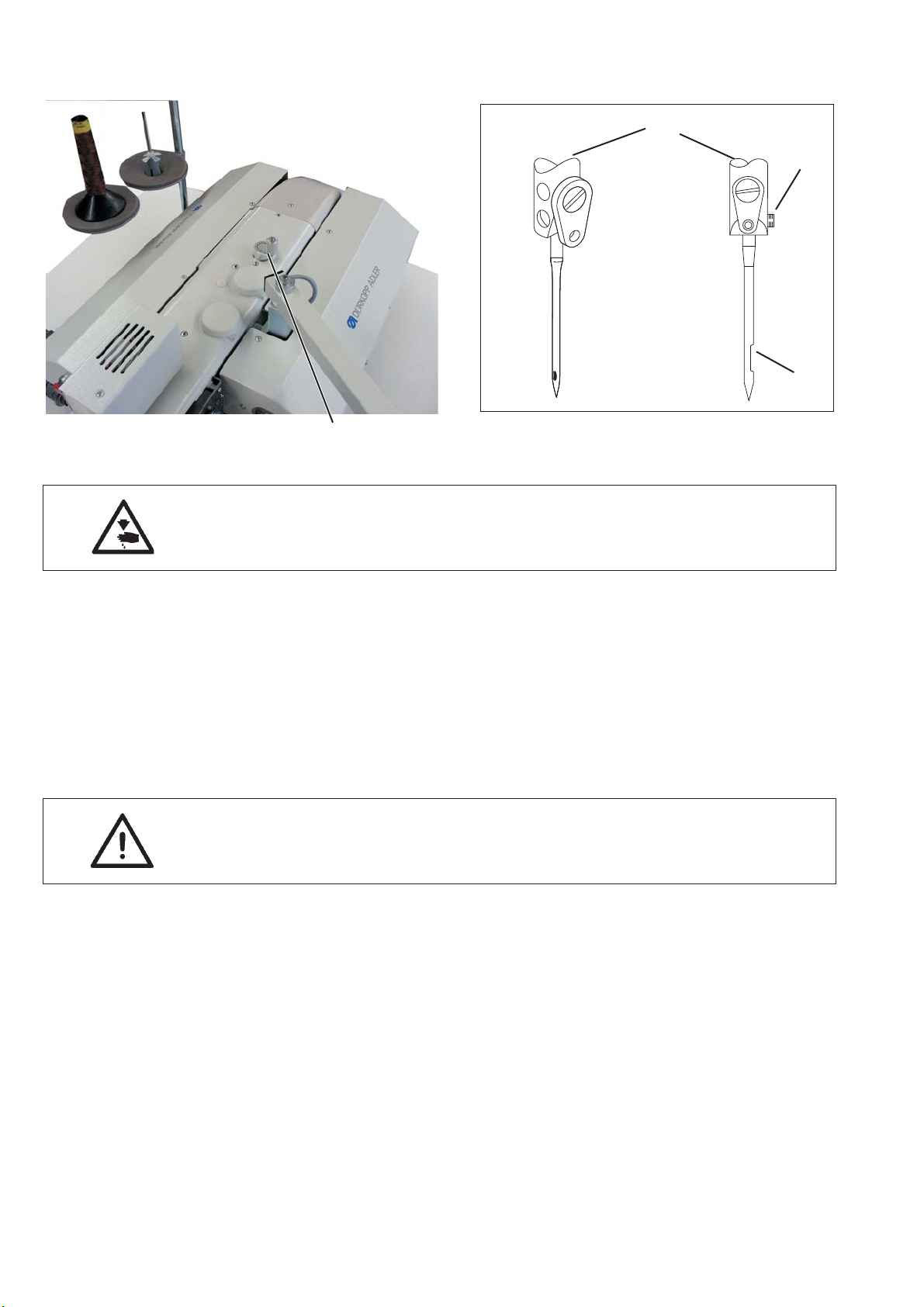
6.3 Changing the needle
1
2
3
4
Caution: Risk of injury!
Turn the main switch off!
The needle may only be changed with the sewing unit switched off.
–
Turn the machine with crank 4 until the needle bar 1 reaches its
highest position.
–
Loosen screw 2.
–
Pull the needle downwards out of the needle bar 1.
–
Insert the new needle into the hole of the needle bar 1 and push it
until it stops.
Caution!
The needle scarf 3 must point towards the hook.
–
Tighten screw 2.
ATTENTION!
When changing to another needle size, the distance between hook
and needle must be readjusted (see service instructions).
Ignoring the above mentioned hint can cause the following errors:
Use of a thinner needle:
Missed stitches
·
Thread damage
·
12
Use of a thicker needle:
Damage on the hook tip.
·
Damage of the needle
·
Page 17

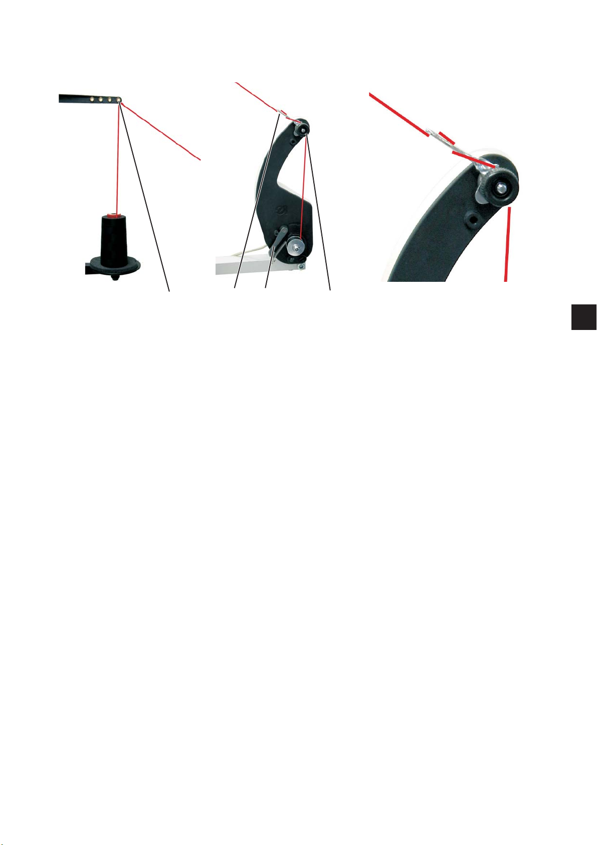
6.4 Threading the needle thread
Caution: Risk of injury!
Turn off the main switch!
The needle thread may only be threaded with the sewing unit
switched off.
11
10
1
2
9
3
1
8
7654
–
Put the thread reel on the thread stand and lead the needle thread
through the unwinder arm.
The unwinder arm must be in vertical position above the thread
reels.
–
Thread in the thread through threading guide 1.
–
Conduct the thread counter-clockwise around the pre-tensioner
wheel 2.
–
Conduct the thread clockwise around the pre-tensioner wheel 3.
–
Conduct the thread through threading guides 4 and 5.
–
Conduct the thread clockwise around the deflector 6.
–
Pull the thread underneath the thread take-up spring 7 and
conduct it through the threading guide 9, the thread regulator 10
to the thread lever 11.
–
Conduct the thread through the thread lever 11 a nd the threading
guide 8.
12
13
14
15
–
Conduct the thread through the needle thread monitor 12, the
thread clamp 13 and the threading guides 14 and 15.
–
Thread the thread into the needle eye.
13
Page 18

6.5 Adjusting the thread regulator
Caution: Risk of injury!
Turn off the main switch.
The thread regulator may only be adjusted with the sewing unit
switched off.
21
The thread regulator 2 controls the quantity of needle thread required
for stitch formation.
The thread regulator must be precisely adjusted for an optimum
sewing result.
With correct setting the needle-thread loop must slide with low
tension over the thickest point of the hook.
–
Loosen screw 1.
–
Adjust the position of the thread regulator 2.
Thread regulator to the left = more thread
Thread regulator to the right = less thread
–
Tighten the screw 1.
Adjustment information:
If the maximum quantity of thread is required the thread-tensioning
spring must be pulled upwards about 0.5 mm from its lower limit
position. This is the case w hen the needle-thread loop passes the
maximum hook diameter.
14
Page 19
6.6 Winding on the hook thread
1
43 2
1
The separate bobbin winder makes it possible to wind the hook thread
independently from the sewing operation.
–
Remove remaining thread from the bobbin hubs before winding.
–
Put the thread reel on the thread stand.
–
Thread the thread through the drill-hole 1 of the unwinder arm.
–
Conduct the thread through threading guide 4.
–
Conduct the thread through the bobbin thread tension 2.
–
Wind up the thread to the right.
Press the bobbin retainer 3 against the bobbin hub.
The bobbin winder starts.
After reaching the set bobbin filling level the bobbin winder stops
automatically.
See Service instructions for setting the bobbin filling level.
15
Page 20
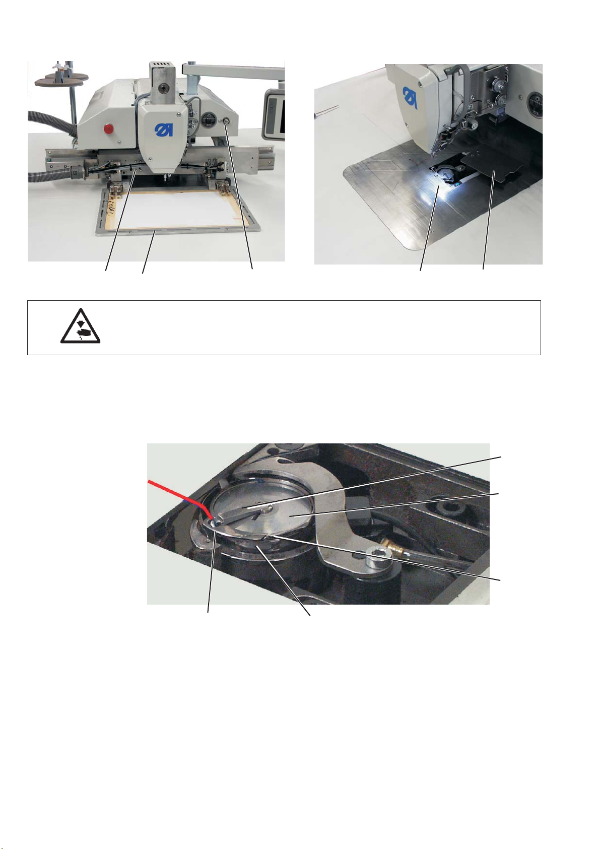
6.7 Changing the hook-thread bobbin
32 1
Caution: Risk of injury!
The hook-thread bobbin may only be changed with the sewing unit in
“safe stop” mode.
–
Remove the material holder 2 (only with change-over frame).
–
Press the key 1 “safe stop”.
The drive carriage rides to the “bobbin change position”.
The cover plate 4 will pivot to the side.
The foot is moved to the lower position.
–
The light 5 is switched on.
54
6
7
16
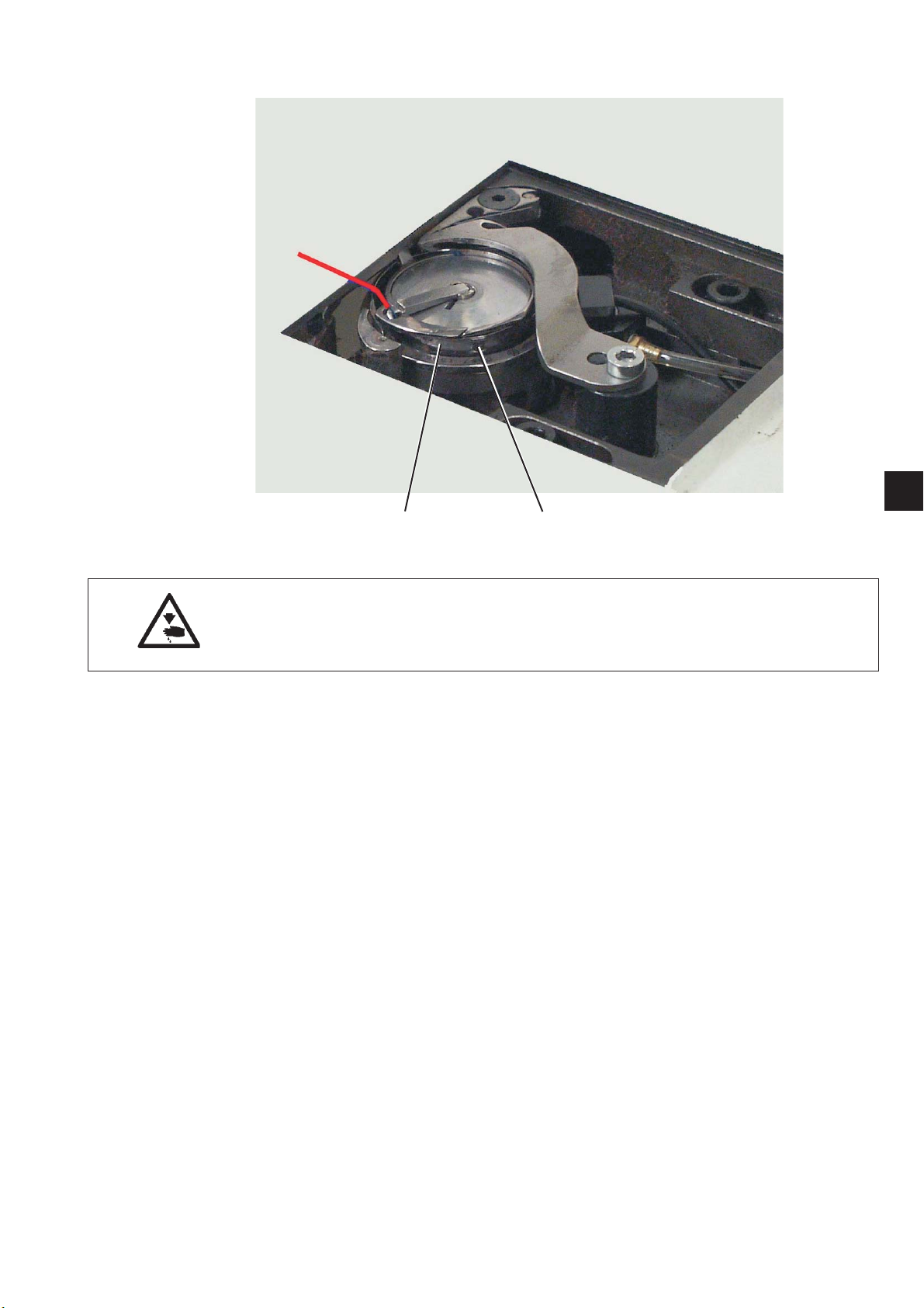
10 9
Remove the empty bobbin.
–
Rise up the flap 6 and remove the empty bobbin.
Insert a full bobbin.
–
Insert the bobbin 7 in a way that it moves in the opposite direction
of the hook when unwinding.
–
Close the flap 6.
–
Conduct the thread through slot 8 and under neath the spring 9.
–
Pull the hook thread through the threading guide 10 and continue
pulling until it stands out about 3 cm.
–
Release key 1 “safe stop”.
The cover plate 4 will pivot back into its original position.
8
Page 21
6.8 Setting the hook thread tension
1
21
Caution: Risk of injury!
Turn off the main switch.
The hook-thread tension may only be adjusted with the sewing unit
switched off.
The necessary hook thread tension should be generated from the
thread tension spring 2.
Setting the tension spring
–
Set the tension spring 2 by turning the adjustment screw 1 until
the needed tension value is reached.
17
Page 22

7. Operating the control of the 911
7.1 The control panel
The data entry is done through a touch screen monitor.
USB connection
USB-Stick order-no. 9805 791113
7.2 Operating the touch screen panel
Activate a function by touching (with a fingertip) the symbol
representing the function in question on the screen.
–
Tip with your fingertip on the requested function symbol.
7.2.1 Window “General”
7.2.2 Input window
18
–
Close the window
“Cancel” “ESC” - > the window will be closed, the value
will not be modified
“OK” “CR” -> the window will be closed and the new
value will be saved, if it is within the
specified limit values
Page 23

7.2.3 Selection window
On this screen, the following actions can be executed:
–
If the button is bright it cannot be activated.
–
A field, in this case the sewing program, has been selected and
can be edited or appended.
1
7.2.4 Numeric input for a parameter
The title bar indicates the parameter group.
The status bar indicates which parameter will be edited.
Underneath the icon, the min. and max. values are displayed. Enter
the corresponding value in the input box.
–
The “DEL” key cancels an input.
19
Page 24

7.2.5 Numeric input for a parameter
–
–
Enter the password.
25483
Touch the button “OK”.
It will be switched over to the technician level.
7.2.6 Input of a text
“ESC” Close the window
“Aa” Switching from capitals to small letters
“DEL” Deleting the last characters
“CR” Close the window, the sequence name will be adopted.
20
Page 25

7.2.7 Radio- button
With the Radio-button the selected option is marked with a black dot.
1
7.2.8 “Scroll bar”
2
Move the scroll bar 2 downwards.
The lower part of t he screen will be displayed.
21
Page 26

7.2.9 Check- button
With the Check-button the selected option is marked with a black x.
7.3 The start screen
The start screen appears after switching the sewing unit on.
–
Press the “Service” button in order to switch to the multitest
program.
–
Press the “Language” button in order to change the selected
language.
22
Page 27

7.4 The main screen
1
23
4
15
14 13 12
1Titlebar
2 Sequence name:
Number of sewing programs in t he sequence
3 Time: Hour: Minute
4 Repair mode
5 Seam patter n size
6 Max. sewing speed
7 Max. thread tension
8 Stitch length
9 Number of stitches / Bobbin thread consumption
10 Button bobbin change
11 Button counter reset
12 Slider, Tabs, Buttons for sequence c ontrol.
The name of the sewing program is in the tabs.
Presently “NP1" is active.
13 Popup-Menu
14 Active sewing program
15 Seam patter n
5
6
7
8
9
10
11
1
23
Page 28

7.5. Pop up menu structure
File
·
Delete
¡
Copy
¡
Open
¡
New
¡
·
·
Seam program
·
Sequence
·
Save as
¡
Edit
Machine parameters
¡
Sequence
¡
Seam program
¡
Parameters
·
Contour adjustment
·
Testing contour
·
Extras
Full screen on/off
¡
Zoom on/off
¡
Service
¡
Adjustments
·
System information
·
Multi-test
·
Initialization and update
·
Manufacturer
·
24
Correction
·
¡
¡
Thread tension
Sewing speed
Page 29

7.6 Menu item “File”
It is possible to sew a single sewing program several times
consequently or to sew several different sewing programs one after
the other in a sequence.
7.6.1 Create a new sewing program
See chapter Teach-in
7.6.2 Creating a new sequence
In this menu item it is possible to occupy the individual memory
locations with sewing programs.
There are a total of 20 independent memory locations available.
Each memory location can be occupied by a sequence of up to 30
sewing programs in any imaginable order.
–
Click File -> New.. -> Sequence
A new sequence will be generated.
1
–
Tip onto the desired sewing program.
In the example NP1
–
Tip onto the button “Insert”. The sewing program is adopted and
will be displayed in t he sequence field.
–
Insert additional sewing programs.
25
Page 30

–
Tip onto the button “Set name”.
–
Enter the name.
–
Press the “Enter” button.
–
Press the “OK” button.
The sequence will be memorized.
26
Page 31

7.6.3 Opening a sewing program or a sequence
Via this menu item, sewing programs or sequences can be opened
from the DAC and then be sewn.
After opening the main screen will be updated accordingly.
–
Click File -> Open
The following screen will appear:
–
Click “File filter”.
The file filter will be opened.
1
According to the selection the following will be displayed:
All files
·
Seam programs (.fnp911)
·
Sequences (.seq911)
·
27
Page 32

7.6.4 Copying a sewing program, a sequence or machine parameters
Via t his menu item it is possible to copy sewing programs, sequences
or machine parameters onto the DAC control or onto a USB-Stick.
And a file filter can also be selected here.
Click File -> Copy
The following screen will appear:
–
Select where to copy from:
- from the DAC control unit to a n USB-stick
or
- from an USB-stick to the DAC control unit
–
Tip on the sewing program or sequence to be copied.
–
Tip on the “Copy” button. The selected program will be copied.
7.6.5 Deleting a sewing program or a sequence
Via this menu item, sewing programs or sequences can be deleted
from the DAC.
And a file filter can also be selected here.
–
Click File -> Delete
The following screen will appear:
–
Tip on the sewing program or sequence to be deleted.
–
Press the “Delete” button.
The program or the sequence will be deleted.
28
Page 33

7.7 Menu item “Edit”
7.7.1 Editing a sewing program
A sewing program consists of a contour and sewing parameters.
The contour (shape of seam) is created via Teach-in or with the help of
the DA-CAD 5000.
The program parameters are divided into different groups and are
modified as follows:
–
Click Edit -> Seam program -> Parameters
The following screen will appear:
1
PP1 - Configuration
Seam name max. 20 characters
minimal foot height
(min. = 1.0 .. max. = 10.0; def. = 10.0 mm )
Limits the programmable foot height to this
value so that with thicker material only this value
has to be adjusted.
Adjust the thread tension
(min. = 10… max. = 200; def. = 100%)
The thread tension profile of the whole contour will be
adjusted according to the percentage value. With the
value 100% no adaptation takes place.
Adjustthenoloadrunspeed
(min. = 10… max. = 200; def. = 100%)
The run speeds will be adjusted accordingly.
Clamp ID-Code
Barcode (ID-Code) max. 10 characters for a security
check before the sewing start (the optional equipment
barcode reader has to be activated)
29
Page 34

Laser marking lamps
Up to four laser marking lamps can be triggered
in order to facilitate the aligning of the material
(The optional equipment has to be activated)
Needle reverse turn mode
The following modes can be set:
Not active
The needle remains in the stopping position.
After the complete contour
After the completion of all the seams of a contour
the needle is tur ned back to the set value
(MP parameter).
After each seam (def.)
After each seam the needle will be turned back.
Needle cooler
(on/off)
Activated/deactivates the needle cooler.
Adjust the sewing speed
(min. = 10… max. = 200; def. = 100%)
The sewing speed will be adjusted accordingly.
PP2 - Load mode
Feeding mode
The following modes can be set:
Mode 1 (def.)
The clamp will be opened in the feeding position.
After actuating the pedal the c lamp will be closed.
After actuating the pedal one more time the seam will
be started.
Mode 2
The clamp will be opened in the feeding position.
After actuating the pedal the left part of the
two-piece clamp for an angular feed will be closed.
After actuating the pedal one more time the right side
will be closed.
After a further actuation of the pedal
the seam will be started.
Mode 3
The clamp will be opened in the feeding position.
After actuating the pedal the right part of the
two-piece clamp for an angular feed will be closed.
After actuating the pedal one more time the left side
will be closed.
After a further actuation of the pedal
the seam will be started.
Mode 4
Quick start mode
The clamp will be opened in the feeding position.
After actuating the pedal the c lamp will be closed.
and the seam will be started. With the
change-over clamp, the seam will be started
automatically after feeding.
This mode is only active if t he quick start
has been enabled with the machine parameters.
In order to activate the quick start mode, the machine
must be switched off and on again!
30
Page 35

Mode 5
The clamp remains closed in the feeding position.
After actuating the pedal one more time
the seam will be started.
Feeding position
(on/off)
With the feeding position activated the clamp
goes to the requested position in order to facilitate
the feeding of the material.
Feeding position X
(min. = -300… max. = 300; def. = 230 mm)
Feeding position Y
(min. = -300… max. = 300; def. = -90 mm)
PP3 - Deposit mode:
Deposit mode
The following modes can be set:
Mode 1 (def.)
The clamp will be opened in the deposit position.
1
Mode 2
The clamp remains closed in the deposit position.
After actuating the pedal the clamp will be opened.
Mode 3
The clamp remains closed in the deposit position.
After actuating the pedal the left part of the
two-piece clamp for an angular feed will be opened.
After actuating the pedal one more time the right side
will be opened.
Mode 4
The clamp remains closed in the deposit position.
After actuating the pedal the right part of the
two-piece clamp for an angular feed will be opened.
After actuating the pedal one more time the left side
will be opened.
Mode 5
The clamp remains closed in the deposit position.
Deposit position
(on/off)
With the deposit position activated the clamp
goes to the requested position after sewing in order
to facilitate the deposit of t he material.
Deposit position X
(min. = -300… max. = 300; def. = 230 mm)
Deposit position Y
(min. = -300… max. = 300; def. = -90 mm)
31
Page 36

PP4 - Soft start
Number of soft start stitches
(min. = 0.. max. = 10; def. 5)
Soft start speed
(min. = 100 .. max. 2000; def. 300 U/min)
PP5 - Sensitivity of the needle thread monitor
(min.=0..max.= 99: def. 5)
Is only active when enabled with the machine parameters.
(The higher the value the less sensitive the upper thread
monitor will be.
99 = The upper thread monitor is s witched off for this
program only.)
PP6 - Thread consumption
Material thickness (min. = 0.. max. 20.0; def. 0)
Thickness of the material when pressed together.
Adjustment of the thread consumption
(min. = -10.0.. max. 10.0; def. 0)
Correction of the calculated values.
PP7 - Move
PP8 - Scale
The contour will be shifted in the requested direction
according to this value.
Move in X direction
(min. = -5.0… max. = 5.0; def. = 0.0 mm)
Move in Y direction
(min. = -5.0… max. = 5.0; def. = 0.0 mm)
The size of the contour will be changed in the direction
desired according to this value.
Scaling in X direction
(min. = 80… max. = 120; def. = 100 %)
100% correspond to the original size.
Scaling in Y direction
(min. = 80… max. = 120; def. = 100 %)
32
Page 37

Center point of scaling in X direction
(min. = -150.0… max. = 150.0; def. = 0.0 mm)
Center point of scaling in Y direction
(min. = -150.0… max. = 150.0; def. = 0.0 mm)
1
33
Page 38

7.7.2 Contour adaptation
Via t his menu item smaller changes of the contour can be adjusted
directly at the sewing unit. Individual stitches can be shifted and
technological operations can be adjusted.
Click Edit -> Seam program -> Contour adjustment
The following screen will appear:
–
Aiming roughly at the position of the contour that is to be adjusted
with the cursor keys.
–
Press the “Go To” Button and the clamp goes to the desired
position.
–
Press the “Continue” button.
34
21
–
Select the corresponding stitch 1.
–
Change the stitch position 2.
–
Press the “Continue” button.
–
Technological operations can be added or modified.
–
Press the “Continue” button.
–
The contour adaptation will be memorized upon confirming the
reque st .
Page 39

7.7.3 Contour test
Via t he menu item a contour can be checked.
Click Edit -> Seam program -> Testing contour
The following screen will appear:
–
Run along the contour with the “Reverse” (backwards) or
“Forwards” (forwards) keys and check it.
1
35
Page 40

7.7.4 Edit the machine parameters
Via t he machine parameters the basic machine settings and some of
the parameters for all programs are defined.
–
Click Edit -> Machine parameters.
MP1 - Configuration
Needle cooling
The following modes can be set:
without
The needle cooler is not activated.
Air cooling (def.)
During sewing the needle is cooled with air.
Ice cooling
Optional equipment.
Sewing foot mode
The sewing foot can be operated in the following modes:
Jumping foot
The sewing foot presses onto the material while the
needle penetrates the material.
Presser foot
The sewing foot presses continuously onto
the material.
Sewing area size
36
Sewing area normal size (def.)
A sewing field of 200*300 mm is available.
Sewing area oversize
In connection with the change-over clamp a
larger sewing field can be used.
Page 41

Optional equipment
Reduced clamp pressure
Optional equipment that facilitates the alignment
by exercising a reduced clamp pressure at the
feeding moment.
Laser marking lamp
Optional equipment that facilitates the alignment
at feeding by providing orientation lines.
Here this option is only enabled and then with
each program up to four laser marking lamps can
be activated.
Bar code reader
Optional equipment for a security check before
the sewing process. With each program a barcode
can be deposited. It will be cross-checked with
the barcode on the clamp.
Only if the codes are identical the sewing process
will be started.
Clamp type
The following kinds of clamps are available:
One-piece clamp for L-shape adaptation
Single-piece parallel clamp with angular feed
One-piece clamp for with bow (def.)
Single-piece parallel clamp with bow feed
Split clamp for L-shape adaptation
Two-piece parallel clamp with angular feed
Exchangeable clamp
Removable clamp
Special clamp
Individual clamp
1
Clamp limitation
Preset limitation (def.)
No additional structures are taken into account.
Special limitation
Individual limits are taken into account.
Set Pedal mode
The following modes are available:
Mode 1
The recent position of the pedal is evaluated.
Mode 2 (def.)
The pedal has to be pushed back into the initial
position after each actuation before a further
actuation is taken into account.
Mode 3
The recent position of the pedal is evaluated.
Additionally the quick start mode is enabled (see
the program parameter feeding mode). The recent
position of the pedal is evaluated.
Additionally the quick start mode is enabled (see
the program parameter feeding mode)
In order to activate the quick start mode, the machine
must be switched off and on again!
Hand switch
In the hand switch mode one sensor is used only for
the operation of the clamp movement (up and down).
The other sensor serves to start the sewing process.
37
Page 42

MP2 - Limit values
Set max. sewing speed
(min. = 500 .. max. 3000; def. 3000 U/min)
Limitation of all sewing programs to this speed.
Set max. run empty speed
(min. = 10 .. max. 100; def. 100%)
Limitation of all clamp movements between seam
to this value.
Set feeding start
(min. = 30 .. max. 350; def. 180 degrees)
At this angle of needle movement the clamp starts
to move during the stitch.
Set feeding phase
(min. = 30 .. max. 100; def. 80%)
This parameter determines how the clamp movement
takes place during the stitch. (At 100% the requested
clamp movement is equally divided over the
whole stitch).
Set needle reversing position
(min. = 0 .. max. 359; def. 0 degrees)
The needle will be turned back to this angle in order
to enlarge the distance to the clamp.
Editing timings distances
This function is reserved for the Dürkopp-Adler service
personnel.
MP3 - Needle thread monitor
Upper thread monitor mode
The following modes are available:
Threading position (def.)
After detecting thread breakage the thread will be
trimmed and the clamp will then go to the threading
position.
Thread cutting
After detecting thread breakage the thread will be
trimmed and the clamp moves according to the
set reverse drive to the contour position.
Pausing
After detecting thread breakage the sewing movement
will be stopped.
Not activated
The needle thread monitor is ignored.
38
Page 43

Set return path after thread breakage
(min.=0..max.20;def.5stitches)
Number of stitches of the reverse drive effectuated after
detection of thread breakage.
Position of bobbin change X
(min. = -300… max. = 300; def. = 230 mm)
Position of bobbin change Y
(min. = -300… max. = 300; def. = +90 mm)
MP4 - Thread cutting
Cutting speed
(min. = 70 .. max. 500; def. 180 U/min)
Speed of the trimming stitch.
Cutting position on
(min. = 0 .. max. 359; def. 180 degrees)
Angular position of the needle at which the thread trimming
knife is switched on.
Cutting position off
(min. = 0 .. max. 359; def. 359 degrees)
Angular position of the needle at which the thread trimming
knife is switched off.
Set thread tension during thread cutting
(min. = 00 .. max. 100; def. 10%)
Thread tension of the trimming stitch.
Position for thread tension during t hread cutting
(min. = 0 .. max. 400; def. 370 degrees)
Starting angle for the thread tension at trimming (with an angle
of more than 359 degrees the t hread tension is only activated
with the next stitch.
MP5 - Clamping thread
1
Closing the thread clamp, first stitch
(min. = 0 .. max. 250; def. 180 degrees)
Starting angle for the closing of the tread clamp during
the first stitch.
Open the thread clamp, first stitch.
(min. = 0 .. max. 359; def. 340 degrees)
Starting angle for the opening of the tread clamp during
the first stitch.
If the angles for closing and opening are identical the t hread
clamp will not be activated.
39
Page 44

MP6 - Counter
Counter type
The following possibilities available:
Increment counter (def.)
After each sewn program the counter will step up.
Decrement counter
After each sewn program the counter will step down.
Increment sequence counter
After each sewn sequence the counter will step up.
Decrement sequence counter
After each sewn sequence the counter will step down.
Reset value for the counter
(min. = 0 .. max. 9999; def. 0)
Reset value for the counter
Set seam count for bobbin reserve
(min. = 0 .. max. 100; def. 0)
After the sewing of the set seams the user will receive a message.
Not active when set to the value 0.
Set capacity for bobbin reserve
(min. = 0.0 .. max. 400.0; def. 0.0m)
After the consumption of t he capacity a message is generated
for the user.
Not active when set to the value 0.
40
Page 45

7.8 Menu item “Extras”
7.8.1 Service
–
Click Extras -> Service -> Adjustments
–
Enter the password
The following screen will appear.
Language
–
Press the requested language.
–
Press the “OK” button.
The selected language will be adopted.
Date and time
–
Enter the date and the hour.
–
Press the “OK” button.
The settings will be adopted.
1
Setting the control panel
Touch Calibration
Contrast Brightness
Touch Test
41
Page 46

Full screen on / off
Full screen off
Full screen on
7.8.3 Zoom on / off
Zoom off
Zoom on
42
Page 47

7.8.2 System information
–
Click Extras -> Service -> System information
The following screen will appear.
Control unit events
A list with the errors that occurred lately will appear.
1
Log configuration
This function is reserved for the Dürkopp-Adler service personnel.
Log visualizer
A list with the last log settings will appear.
State of the operation panel
After effectuating the button the status will appear in the log display.
43
Page 48

7.8.3 Multitest
–
Click Extras -> Service -> Multi-test .
The following screen will appear.
Switching input/output elements
Test the input elements
With this test function the functioning of the input
elements will be tested.
Caution: Risk of injury!
Do not reach into the running machine during the function test of the
input elements.
–
Press the button “Input elements”.
–
Press “selected”.
–
Enter the desired input element and select it.
Input number Signification
S1 Clamp to the right below
S2 Clamp to the left below
S9 Upper thread monitor active
S10 Bobbin cover closed
S11 Machine head lock closed
S13 Pedal forwards
S14 Pedal backwards
S16 Pre ss u re monit or
S17 Quick stop
S100 Reference sewing motor
S101 Ref. X-axis
S102 Ref. Y-axis
S103 Ref. Z-axis
44
Page 49

Test the output elements
With this test function the functioning of the output
elements will be tested.
Caution: Risk of injury!
Do not reach into the running machine during the function test
of the output elements.
–
Press the button “output elements”.
–
Press “selected”.
–
Enter the desired output element and select it.
Output number Signification
Y1 Sewing foot mode:
Y2 Open the bobbin case latch
Y3 Needle cooler on
Y4 Clamp right side
Y5 Clamp left side
1
Y9 Lamp thread in button on
Y10 Warning light oil level on
Y25 Laser marking lamp 1 (Z)
Y26 Laser marking lamp 2 (Z)
Y27 Laser marking lamp 3 (Z)
Y28 Laser marking lamp 4 (Z)
45
Page 50

Test sewing motor
With this program the sewing motor is tested.
CAUTION !
Pull out the threads from needles a nd thread lever.
–
Enter the sewing speed.
(300 … 2000 U/min)
–
Enter the trimming speed.
(70 .. 500 U/min)
–
Press “Start”.
The sewing motor runs with the set speed.
–
Press “Stop”.
The sewing motor stops.
–
Press “Stop”.
The sewing motor stops automatically and the thread
trimmer is actuated.
46
Page 51

Feed clamp
This function is reserved for the Dürkopp-Adler service personnel.
Set stroke position
Perform a reference run
Switching between jumping and presser foot
Set the drives currentless
Go to a position
1
47
Page 52

7.8.5 Initialization and Update
–
Click Extras -> Service -> Initialization and Update.
–
Enter the password
The following screen will appear.
Control unit initialization
ATTENTION!
All entries will be set back to factory setting.
7.8.6 Manufacturer
Operation panel initialization
ATTENTION!
All entries will be set back to factory setting.
Update of the control unit
This menu is only accessible for Dürkopp Adler personnel.
48
Page 53

7.9 Menu item “Correction”
7.9.1 Thread tension
Upon changing this parameter all seams that are sewn subsequently
will be adjusted. With v alues below 100% all the thread tensions and
sewing speeds will be reduced. With values above 100% all the thread
tensions and sewing speeds will be increased.
These adjustments are only scheduled for a short “trial period” and
only remain set until the machine is switched off.
–
Click Correction -> Thread tension.
The following screen will appear.
1
7.9.2 Sewing speed
–
Enter the desired thread tension value.
(10 … 200)
–
Press the “OK” button.
–
Click Correction -> Sewing speed.
The following screen will appear.
–
Enter the desired sewing speed.
(10 … 200)
–
Press the “OK” button.
ATTENTION !
The values changed here are not automatically saved.
Should the changes be saved, please enter the values in the
sewing program (see chapter 7.7.1).
49
Page 54

7.10 Menu item “?”
7.10.1 Info
This screen indicates the current software version.
–
Click ?->Info.
The following screen will appear.
50
Page 55

7.11 Teach-in
With the sewing unit 911 it is possible to create freely defined seam
contours and to memorize them in the control unit. The contour data
are entered at the control panel.
Line not sewing
Via t his menu item a line can be created that will not
be sewn.
1
Line sewing
Via t his menu item a line can be created that will be sewn.
Circular arc
Via t his menu item a circular arc can be created.
Param…
Via this menu item the parameters that correspond to
the line or the circular arc are entered.
Sewing speed (min = 500 .. max. = 3000 U/min)
Stitch length (min. = 0.1 max. = 12.7 mm)
51
Page 56

Thread tension value
Lift stroke ( min. = 1 mm, max. = 10 mm)
Thread trimming
Delete
Via this menu item the line/circular arc entered last can
be deleted.
Memo…
Via this menu item the newly created seam contour
is memorized.
ñòñò Clamp movement
By pressing on of the arrow keys a clamp movement
into the corresponding direction is effectuated.
X=0.0 Y=0.0 Position request
By pressing on the area of the current clamp position
an edit window will pop up in which the new position
can be entered. After confirming the position by
pressing “OK” the clamp will go to the requested position.
Pedal actuation
Depending on the preselected direction of the
movement the clamp goes step by step to the right/left
or downwards/upwards.
52
Page 57

7.11.1 Creating a new seam contour
Step 1
–
–
In the first step the starting point of the seam segment
is determined.
1
Go to the desired starting point by using the arrow keys “ñ ”,
“ò ”,“ñ ”or“ò ”.
Press the “ OK ” button.
The starting point will be adopted.
The starting point will be displayed in green.
ATTENTION !
Pay attention to the specific clamp limits so that the seam contour is
inside the possible sewing field and that no collision will take place!
Run a contour test in order to check the clamp motion.
The sewing can be started afer a successful run.
The input of circular arcs requires particular attention since the
intermediate points will be interpolated!
53
Page 58

Step 2
In the second step it will be determined whether:
a non sewing line
·
a line or a circular arc will be sewn.
·
–
Select the desired button for the next entry.
–
Select the “Line sewing” or “circular arc” button. The menu for the
seam parameters will pop up.
Step 3
–
Enter the seam parameters for t he new seam segment.
–
Enter the desired seam segment by using the arrow keys “ñ”,
“ò”,“ñ”or“ò”.
–
Enter all further seam segments.
–
Press the “Memorize” button.
Enter the desired name and press “ Enter ”.
54
–
Adjust the program parameters.
ATTENTION !
Run a contour test in order to check the contour movement. After
a successful test the seam can be sewn.
Page 59

7.12 Repair mode
Via this button the repair mode can be called up.
That way a faulty seam contour, for example after a thread breakage
can be resewn from a certain point.
–
Switch on the repair mode.
–
Go to the point from where the sewing shall continue with the two
buttons “Forwards” (forwards) or “Reverse" (backwards).
–
Press the “Continue sewing” button.
From this repair point the seam will be sewn to the seam end.
1
55
Page 60

7.13 Thread breakage
After a thread breakage the thread can be threaded in again and the
sewing of the seam contour can be continued from any point.
–
Press the “Bobbin change” button.
The work clamp will go t o the bobbin change position.
–
Change the bobbin
–
Go to the point from where the sewing shall continue with the two
buttons “forwards” or “backwards”.
–
Press the “Continue sewing ” button.
From this repair point the seam will be sewn to the seam end.
56
Page 61

8. DA-CAD 5000
Selecting the machine class
With the program DA-CAD 5000 that is optionally available, sewing
programs can be created with an ordinary PC.
For the exact description please read the “Instruction manual
DA-CAD 5000".
1
Creating the seam contour
In the first step the machine class is selected.
In the second step the seam contour is drawn.
57
Page 62

Memorizing the seam contour
In the last step the finished seam program is copied onto a USB-stick.
In order to do so select the following menu item:
Data transmission
-> USB-Memory stick
-> Memorize (PC->USB)"
After successful memorizing on the USB-stick the following steps
have to be effectuated on the machine:
- Plug in the USB-stick and copy the desired data file onto the DAC.
- Open the copied program.
- Adjust the program parameters (particularly the min. sewing foot
height!).
- Run a contour test in order to check the c ontour movement.
- After successful checking/adjustment the program can be sewn.
58
Page 63

9. Error messages/Information messages
9.1 Error messages
Error code Description Remedy
Sewing motor
1051 Sewing motor timeout
- Faulty cable to the sewing motor reference
switch
- Faulty reference switch
- Machine head rough-running or belt tension too
high
1052 Sewing motor excess current
- Faulty sewing motor cable
- Faulty sewing motor
- Faulty control
1053 Sewing motor mains voltage too high
1055 Sewing motor overload
- Sewing motor blocked/seized up
- Faulty sewing motor
- Control faulty
1056 Sewing motor overheat
- Sewing motor seized up
- Faulty sewing motor
- Control faulty
1058
1302
1342
1344
Stepping motors
Sewing motor speed
- Faulty sewing motor
Failure sewing motor IDMA Autoincrement
Control receives no impulse from impulse
transmitter in the motor
Faulty sewing motor
Internal error
- Replace the cable
Replace the reference switch
- Check whether machine head is
rough-running
and belt tension
- Replace the sewing motor cable
- Replace the sewing motor
- Replace the control
Check the mains voltage
- Eliminate blocking/seizing
- Check the sewing motor
- Check the control
- Eliminate seizing
- Replace sewing motor
- Replace the control
- Replace the sewing motor
- Check the cable from the impulse
transmitter in the motor to the
control
- Switch the machine off and on
again
- Software update
1
2101 Stepping motor X-axis time out referencing
- Setting reference switch faulty
- Faulty cable to the reference switch
- Faulty reference switch
2102 Stepping motor X-axis faulty current supply
- Stepping motor blocked
- Encoder cable disconnected/faulty
- Encoder faulty
2152 Stepping motor X-axis excess current
2153 Stepping motor X-axis excess voltage
- Mains voltage too high
2155 Stepping motor X-axis overload
- Feeding system rough-running
- Obstacles at feeding movements
- Ali gn the referen ce swit c h
- Replace the cable
- Check the reference switch
- Remove the blocking
- Check/replace the encoder cable
- Replace the stepping motor
- Replace the stepping motor
- Replace the control
Check the mains voltage
- Remove the blocking
- Remove the obstacles/
Adapt the movements
59
Page 64

Error code Description R emedy
2156 Stepping motor X-axis overheat
- Stepping motor seized up
- Faulty stepping motor
- Control faulty
- Eliminate seizing
- Replace stepping motor
- Replace the control
2201 Stepping motor Y-axis time out referencing
- Setting reference switch faulty
- Faulty cable to the reference switch
- Faulty reference switch
- Al ig n the referenc e switc h
- Replace the cable
- Replace the reference switch
2202 Stepping motor Y-axis faulty current supply
- Stepping motor blocked
- Encoder cable disconnected/faulty
- Encoder faulty
- Remove the blocking
- Check/replace the encoder
cable
- Replace the encoder
2252 Stepping motor Y-axis excess current
- Replace the stepping motor
- Replace the control
2253 Stepping motor Y-axis excess voltage
- Mains voltage too high
Check the mains voltage
2255 Stepping motor Y-axis overload
- Feeding system rough-running
- Obstacles at feeding movements
- Remove the blocking
- Remove the obstacles/
Adapt the movements
2256 Stepping motor Y-axis overheat
- Feeding system blocked
- Faulty stepping motor
- Control faulty
- Eliminate seizing
- Replace stepping motor
- Replace the control
2301 Stepping motor stroke position time out
referen c in g
- Setting reference switch faulty
- Faulty cable to the reference switch
- Al ig n the referenc e switc h
- Replace the cable
- Replace the reference switch
- Faulty reference switch
2302 Stepping motor stroke position faulty current
supply
- Stepping motor blocked
- Encoder cable disconnected/faulty
- Encoder faulty
2352 Stepping motor stroke position excess current
- Remove the blocking
- Check/replace the encoder
cable
- Replace the stepping motor
- Replace the control
2353 Stepping motor stroke position excess voltage
Check the mains voltage
- Mains voltage too high
2355 Stepping motor stroke position overload
- Feeding system rough-running
- Obstacles at feeding movements
- Remove the blocking
- Remove the obstacles/
Adapt the movements
2356 Stepping motor stroke position overheat
- Feeding system blocked
- Faulty stepping motor
- Control faulty
- Eliminate seizing
- Replace stepping motor
- Replace the control
Control/Machine
3100 Machine control voltage
Temporary mains voltage drop
3102 Machine voltage intermediate circuit sewing motor
Temporary mains voltage drop
3103 Machine voltage intermediate circuit stepping
motors
Temporary mains voltage drop
60
Check the mains voltage
Check the mains voltage
Check the mains voltage
Page 65

Error code Description R emedy
3107 Machine temperature
- Vent holes closed
- Ventilation grid soiled
3109 Safe stop is switched on
3121 Insufficient or missing compressed air
3123 Oil sensor active
3210 Thread breakage
3215 Empty bobbin (Residual thread monitoring)
3220 Empty bobbin (Residual thread monitoring)
3500 Error calculation of the contour data
3501 Aim position of XY-clamp outside the movement
limits
3502 Aim position of XY-clamp within “defended areas”
- Check the vent holes
- Clean the ventilation grid
Switch off the safe stop
Increase the flow or stabilize the
compressed air
Topupoil
Re-thread the thread again
Insert a full bobbin.
Insert a full bobbin.
- Reload contour data
- Check contour data
Adjust the contour data
Adjust the contour data
3721
3722
Control/Machine
4201 Inter nal CF-card faulty
5301 Program not sewable
6551
6554
6651
6653
6751
6761
6952 Error stepping motor drive
Communication
Internal error
Error machine head position/ AD-Converter/
Processor error
Internal error
Internal error
- Switch the machine off and on
again
- Software update
- Inform the DA-Service
- Switch the machine off and on
again
- Ret ro fi t/ re pl a ce the contro l
- Copy the program to the DAC
- Switch the machine off and on
again
- Software update
- Inform the DA-Service
- Switch the machine off and on
again
- Software update
- Inform the DA-Service
1
7801 Communication control panel interface
- Line interruption
-Cable
8151
8156
8159
8152
8154
IDMA error
-Failure
- Faulty control
IDMA error
- Inter nal error
- Switch the machine off and on
again
- Software update
- Inform the DA-Service
- Switch the machine off and on
again
- Replace the control
- Switch the machine off and on
again
- Software update
- Inform the DA-Service
61
Page 66

Error code Description Remedy
8252
8257
Error booting ADSP/ Booting Xilinx/ Booting
Fault
- Switch the machine off and on
again
8258
8256
8254
8351 Error t estpins
- Switch the machine off and on
again
- Software update
- Inform the DA-Service
9601 Stop during sewing on the contour
Continue sewing process?
9700 The latch for the bobbin change is not closed
OK-key = Continue sewing
ESC-key = Abort sewing process
Close the latch for the bobbin
change
9701 Parallel clamp not down
- Remove obstacles
- Align the sensors
9900 Machine parameters faulty
9901 Faulty sequences
9902 Faulty program parameters
Initialize data
Initialize data
Initialize data
62
Page 67

9.2 Information messages
Info Description Remedy
8400 The control panel has no valid program for the DAC
8401
8402
8403 The program in the DAC is no more up-to-date
8404
8407
8408 Waiting for the reset by the DAC
8411 Checking of the DAC program active
8414 Successful update of the DAC
8801
8805
8806
8890
8891
System
9000 Reference run active
9002 Machine head not locked Lock the machine head
9006 Quick stop switch is actuated
9016 Wrong barcode-ID
9100 The counter has not reached the preset value
The control panel has no valid program for the DAC
Faulty update of the DAC
Error testpins/ Signal- / Event processing/ Memory
wrapper /List of functions
Internal error
Load the current program onto the
control panel with a USB-stick
Load the current program onto the
control panel with a USB-stick
Load the current program onto the
DAC
- Re-try update
- Check the cable connection
- Replace the DAC
Wait until restart is finished (takes a
few seconds)
Wait until checking is finished (takes
a few seconds)
- Switch the machine off and on
again
- Software update
- Inform the DA-Service
Releasethequickstopswitch
Change the program
Actuate the OK-key. The counter
will then be reset
1
63
Page 68

10. Maintenance
10.1 Cleaning and Checking
Caution: Risk of injury!
Turn the main switch off!
The maintenance may only be carried out with the sewing unit
switched off!
Maintenance work must be carried out no less frequently than at the
intervals given in the tables (see “operating hours” column).
Maintenance intervals may need to be shorter when processing
heavy-shedding materials.
A clean sewing unit is a trouble-free sewing unit.
1
Maintenance work Explanation Operating
to be carried out hours
Machine head
8
- Remove sewing dust,
lint and thread waste
(e.g. with an air blow gun)
Control box
Places in special need of cleaning:
- - Area around the needle 1
- Area around the hook 2
- Keep the ventilation grid free
8
2
64
Page 69

10.2.Oil lubrication
1
1
Caution: Risk of injury!
Oil can cause skin rashes.
Avoid longer skin contact.
After contact wash yourself thoroughly.
ATTENTION!
The handling and disposal of mineral oils is subject to legal
regulations.
Deliver used oil to an authorized collecting station.
Protect your environment.
Be careful not to spill any oil.
To lubricate the sewing unit use only DA 10 lubricating oil or an
equivalent oil with the following specifications:
–
Viscosity at 40° C: 10 mm²/s
–
Ignition point : 150° C
DA 10 is available from DÜRKOPP ADLER AG retail outlets under the
following parts number:
250 ml container: 9047 000011
1-litre container: 9047 000012
2-litre container: 9047 000013
5-litre container: 9047 000014
Maintenance work Explanation Operating
to be carried out hours
Lubrication of
the sewing unit
The sewing unit is equipped with a central oil
wick lubrication. The bearings are supplied out
of oil reservoir 1.
8
- The oil level must not fall below the marking
line 3 (MIN) of the oil reservoir.
- Fill in oil through the bore hole 2 up to the
marking line “Max”.
65
Page 70

Notes:
66
 Loading...