

Page 1

869
Spezialnähmaschine
Serviceanleitung
Service Instructions
D
GB
Postfach 17 03 51, D-33703 Bielefeld • Potsdamer Straße 190, D-33719 Bielefeld
Telefon +49 (0) 521 / 9 25-00 • Telefax +49 (0) 521 / 9 25 24 35 • www.duerkopp-adler.com
Ausgabe / Edition: Änderungsindex Teile-Nr./Part.-No.:
04/2010 Rev. index: 00.0 Printed in Federal Republic of Germany 0791 869641
Page 2

Alle Rechte vorbehalten.
Eigentum der Dürkopp Adler AG und urheberrechtlich geschützt. Jede, auch auszugsweise
Wiederverwendung dieser Inhalte ist ohne vorheriges schriftliches Einverständnis der Dürkopp Adler AG
verboten.
All rights reserved.
Property of Dürkopp Adler AG and copyrighted. Reproduction or publication of the content in any manner,
even in extracts, without prior written permission of Dürkopp Adler AG, is prohibited.
Copyright ©
Dürkopp Adler AG - 2010
Page 3

General safety instructions
The non-observance of the following safety instructions can cause
bodily injuries or damages to the machine.
1. The machine must only be commissioned in full knowledge of the
2. Before putting into service also read the safety rules and
3. The machine must be used only for the purpose intended. Use of
4. When gauge parts are exchanged (e.g. needle, presser foot, needle
5. Daily servicing work must be carried out only by appropriately
instruction book and operated by persons with appropriate training.
instructions of the motor supplier.
the machine without the safety devices is not permitted. Observe all
the relevant safety regulations.
plate, feed dog and bobbin) when threading, when the workplace is
left, and during service work, the machine must be disconnected
from the mains by switching off the master switch or disconnecting
the mains plug.
trained persons.
6. Repairs, conversion and special maintenance work must only be
carried out by technicians or persons with appropriate training.
7. For service or repair work on pneumatic systems, disconnect the
machine from the compressed air supply system (max. 7-10 bar).
Before disconnecting, reduce the pressure of the maintenance unit.
Exceptions to this are only adjustments and functions checks made
by appropriately trained technicians.
8. Work on the electrical equipment must be carried out only by
electricians or appropriately trained persons.
9. Work on parts and systems under electric current is not permitted,
except as specified in regulations DIN VDE 0105.
10. Conversion or changes to the machine must be authorized by us
and made only in adherence to all safety regulations.
11. For repairs, only replacement parts approved by us must be used.
12. Commissioning of the sewing head is prohibited until such time as
the entire sewing unit is found to comply with EC directives.
13. The line cord should be equipped with a country-specific mains
plug. This work must be carried out by appropriately trained
technicians (see paragraph 8).
It is absolutely necessary to respect the safety
instructions marked by these signs.
Danger of bodily injuries !
Please note also the general safety instructions.
Page 4

Page 5

Contents Page:
Part 3: Service Instructions - Class 869
(Edition 04/2010)
1. General information
1.1 Gauges..................................................... 3
1.2 Descriptionofthelockingpositions ................................... 4
1.3 Graduatedscaleonthehandwheel ................................... 5
2. Sewing machine
2.1 Positionofthearmshaftcrankonthearmshaft............................ 6
2.2 Topandbottomtoothedbeltwheel/toothbelt ............................ 7
2.2.1 Positionoftheuppertoothedbeltwheel ................................ 7
2.3 Bottomfeedandstitchregulatorgear.................................. 8
2.3.1 Basicsettingstitchadjustment...................................... 8
2.3.2 Settingthe2ndstitchlength........................................ 10
2.3.3 Basicfeedsetting .............................................. 11
2.3.4 Positionofthefeeddoginthethroatplatecutout .......................... 12
2.3.5 Feedingmotionofthefeeddog...................................... 13
2.3.6 Liftingmotionofthefeeddog....................................... 14
2.3.7 Switchingofftheliftingmotionofthefeeddogforedgingwork .................. 15
2.3.8 Feeddogheight ............................................... 16
2.4 Transmissionlever.............................................. 17
2.5 Needlebarlinkage.............................................. 18
2.5.1 Aligningneedlebarlinkagelaterally ................................... 18
2.5.2 Needleholeinfeeddirection........................................ 19
2.6 Hook,loopingstrokeandneedlebarheight............................... 20
2.6.1 Looping stroke ................................................ 20
2.6.2 Needlebarheight .............................................. 21
2.6.3 Distance between hook and needle.................................... 22
2.6.4 Needleguard................................................. 23
2.7 Bobbin housing elevator .......................................... 24
2.7.1 General..................................................... 24
2.7.2 Bobbin housing elevator path ....................................... 24
2.7.3 Elevationtime................................................. 25
2.8 Feedfootandmaterialpresserfoot.................................... 26
2.8.1 Feedfootandmaterialpresserfootstroke ............................... 26
2.8.2 Feedfootstrokemovement ........................................ 27
2.8.3 Sewingfootpressure ............................................ 28
2.9 Stitchlengthlimitation ........................................... 29
2.10 Consistentforwardandreversestitches................................. 30
2.11 Sewingfootelevation............................................ 31
211.1 Sewing foot lifting (mechanical) ...................................... 31
2.11.2 Height of the sewing feet locked with the hand lever ......................... 32
2.11.3Heightoftheraisedsewingfeet...................................... 33
2.12 Threadguidingparts............................................. 34
GB
Page 6

Contents Page:
2.12.1Threadregulator............................................... 34
2.12.2Threadtakeupspring............................................ 35
2.13 Bobbinwinder................................................. 36
2.14 Threadcutter................................................. 38
2.14.1Threadpullingknifeheight......................................... 38
2.14.3Threadpullingknife............................................. 39
2.14.4Cutterpressureandbobbinthreadclamp................................ 40
2.14.5Cuttingposition................................................ 43
2.15 Potentiometerinthearm.......................................... 44
2.15.1 Basic setting without control panel .................................... 44
2.15.2BasicsettingwithV810orV820controlpanel............................. 45
2.15.3Testingthepotentiometeradjustment.................................. 46
2.16 Oillubrication................................................. 47
2.17 Maintenance.................................................. 48
Page 7
1. General
These service instructions describe how to set up the special 869
sewing machine.
IMPORTANT!
The tasks described in these service instructions must only be carried
out by qualified or appropriately trained people.
Caution: Danger of injury!
Turn off the main switch for repair, conversion and maintenance work
and disconnect the machine from the pneumatic supply system.
Only carry out adjustment work and function tests when the machine
is running with the greatest care and observing all safety measures.
These service instructions describe how to set the sewing machine up
in a practical order. With this it must be noted that different setting
positions depend on each other. Therefore, adjustments must be
made in the order described.
A new, perfect needle must be used for all adjustment work on stitch
creating parts.
Machine covers that must be unscrewed and screwed back on again
for inspection and adjustment work are not mentioned in the text.
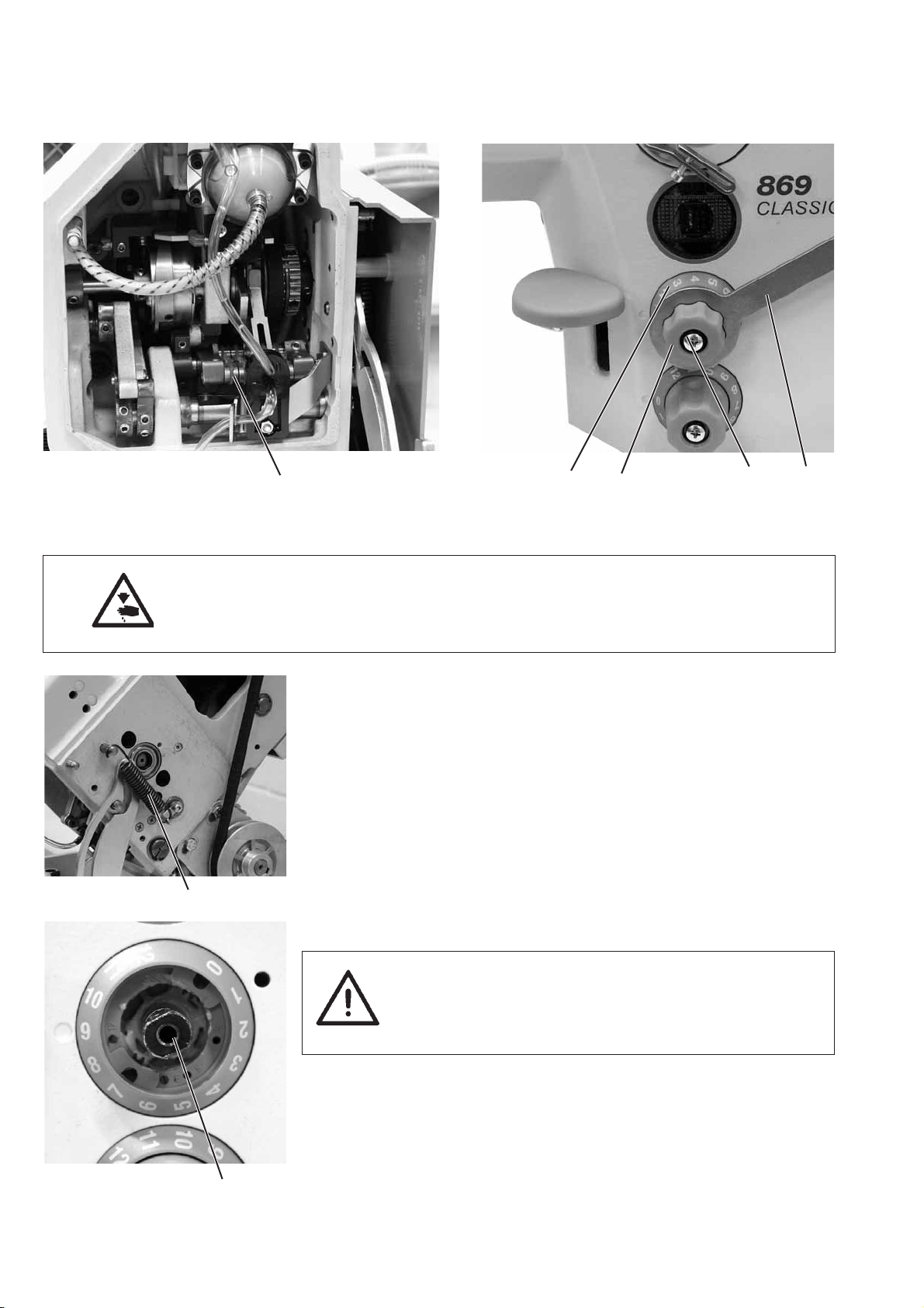
1.1 Gauges
GB
Important
On the special 869 machine some shafts have flat spots that make it
considerably easier to adjust the machine.
For all adjustments on the flat spot each time the first screw is
screwedinthedirectionofrotationontheflatspot.
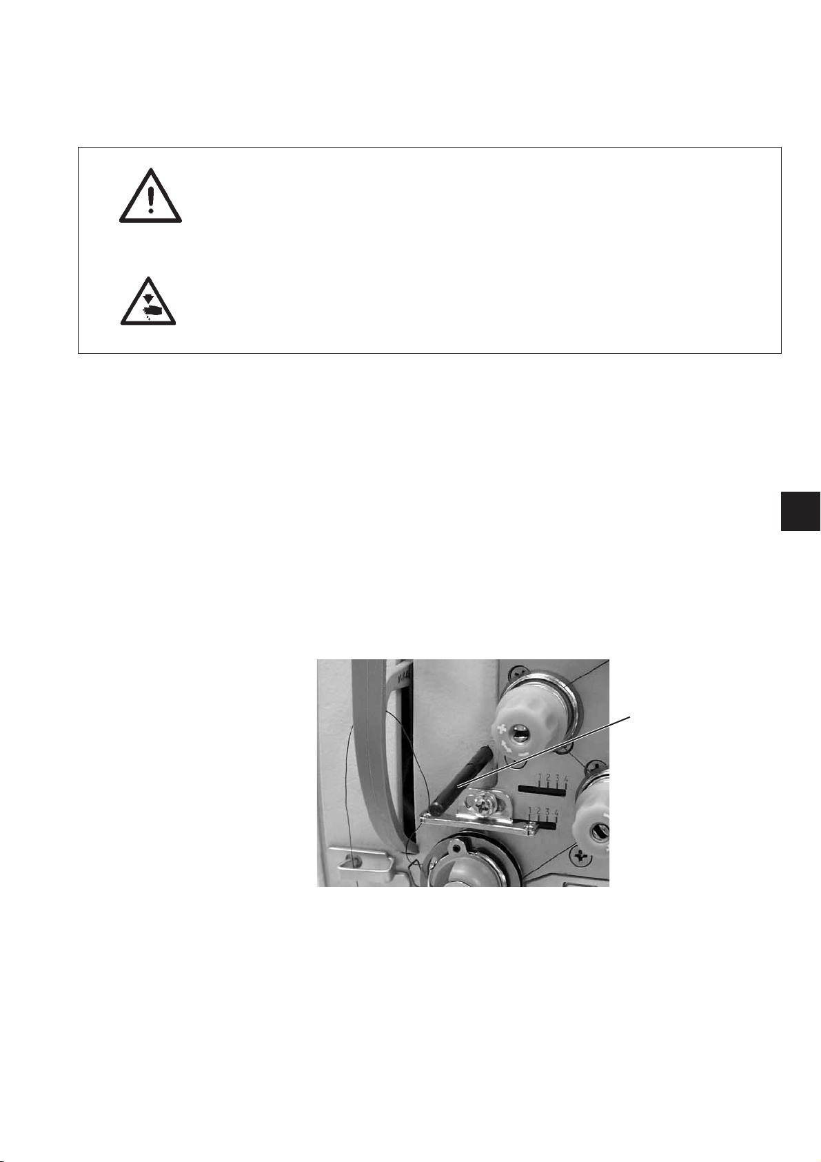
1
The locking pin 1 required to set the machine is provided as standard
with the machine. It is in the machine’s accessories’ kit and can be
fixed to the bottom of the oil sump so that it is easy to get to.
3
Page 8
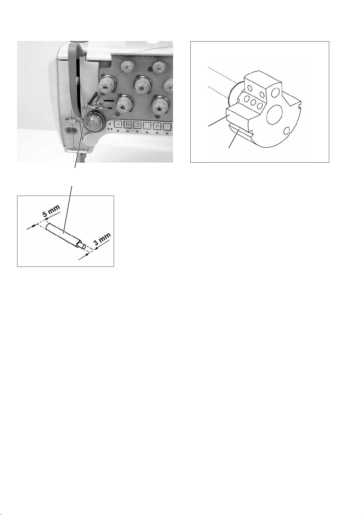
1.2 Description of the locking positions
1
With the locking pin 1 and the marking grooves 2 and 3 in the needle
bar crank 4 the sewing machine can be locked in two setting
positions.
Position I = Ø 5 mm locking pin for large groove
Position II = Ø 3 mm locking pin for small groove
4
2
= loop stroke, needle bar height
= needle bar at top dead centre, graduated scale on hand
wheel
4
Page 9

1.3 Graduated scale on the hand wheel
The hand wheel 2 is printed with graduated numbers.
Specific settings are configured using these hand wheel settings.
–
Turn the hand wheel until it reaches the graduated figure specified
in these instructions on the indicator 3.
–
Set as described.
1
2
3
Setting the hand wheel
–
Move the machine to position II with the Ø 3 mm locking pin.
–
Undo the hand wheel fixing screws through hole 1.
–
Turn the hand wheel until the number “0" shows on the indicator 3.
–
Screw in t he first fixing screw again.
–
Turn the hand wheel 50° and screw in the second fixing screw.
GB
5
Page 10
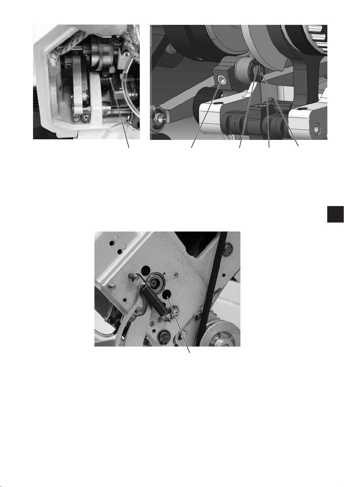
2. Sewing machine
2.1 Position of the needle bar crank on the arm shaft
21
2
4
3
1
Caution: Danger of injury!
Turn off the main switch.
Only check and adjust the position of the needle bar crank when the
machine is switched off.
Standard checking
The needle bar crank 1 is fixed to the arm shaft with the two screws 2.
The screws must be seated on the flat spot 3.
Correction
–
Undo screws 2 on the needle bar crank.
–
Turn the needle bar crank on the shaft so that the screws 2 are
seated on the flat spot 3.
–
Push the needle bar crank axially to the right until it will go no
further.
–
Screw in the scre ws 2.
6
Page 11
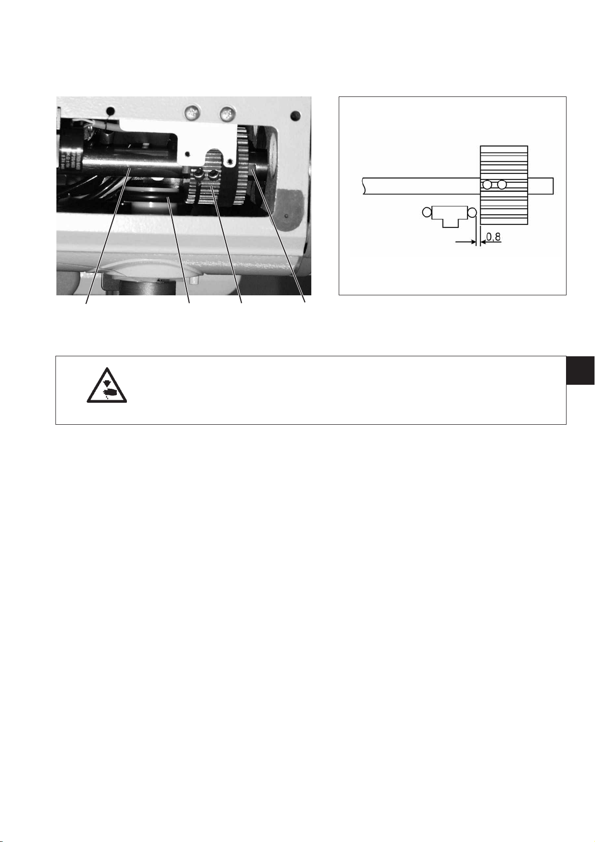
2.2 Top and bottom sprocket belt wheel/ tooth belt
2.2.1 Position of the top sprocket belt wheel
4321
Caution: Danger of injury!
Turn off the main switch.
Only check and adjust the position of the top sprocket belt wheel
when the machine is switched off.
Standard checking
The sprocket belt wheel 2 is fitted to the arm shaft 4 with two screws.
The screws must be seated on the flat spot 1.
The distance between the sprocket belt wheel 2 and the bobbin
winder wheel 3 must be 0.8 mm when the bobbin winder is out of
action.
–
Check the distance between the sprocket belt wheel 2 and the
bobbin winder wheel 3 with a feeler gauge.
Correction
–
Undo the grub screws on the sprocket belt wheel.
–
Turn the sprocket belt wheel until the screws sit on the flat spot 1
of the arm shaft.
–
Set the lateral distance of 0.8 mm between the sprocket belt
wheel 2 and the bobbin winder wheel 3 with a feeler gauge.
–
Tighten the grub screws on the sprocket belt wheel.
GB
7
Page 12
2.3 Bottom feed and stitch adjustment gear
2.3.1 Basic stitch adjustment setting
1
Caution: Danger of injury!
Turn off the main switch.
Only set the basic stitch adjustment when the sewing machine is
switched off.
Standard checking
When the adjustment wheel 5 is set to “0" the stitch adjuster drive 1
must have as little play as possible.
–
Turn the adjustment wheel 5 to stitch length “0".
–
Check the play on the stitch adjuster drive 1.
Correction
–
Unhook spring 2.
–
Fix the adjustment wheel 5 with the spanner 3.
–
Remove screw 4 and remove the adjustment wheel 4.
2
–
Turn the shaft 7 to the right with a 10 mm open ended spanner
until the stitch regulator lever 1 has a little play as possible.
65 4 3
CAUTION Risk of breaking!
Do not turn the shaft too far to the right.
The stitch adjustment parts may get jammed and the
maximum stitch length of 9 mm or 6 mm will not
be reached.
–
Set scale 6 to “0".
–
Replace adjustment wheel 5 and fix with screw 4.
–
Check the play on the stitch regulator lever 1.
–
Hook spring 2 on again.
7
8
Page 13
1
Setting the eccentric
The eccentric 2 must be set so that the marking 4 on eccentric 2
points away from the shaft 1.
–
Undo screw 3.
–
Turn eccentric 2 accordingly through hole 5.
–
Tighten screw 3.
3412
GB
5
9
Page 14
2.3.2 Adjust the 2ndstitch length
4321
Caution: Danger of injury!
Turn off the main switch.
Only set the basic stitch adjustment when the sewing machine is
switched off.
–
Turn the top adjustment wheel 1 to “4".
–
Remove screw 2 and remove the adjustment wheel 3.
–
Turn the shaft 5 carefully clockwise with a 10 mm open ended
spanner until it will go no further.
–
Turn scale 4 to position “4".
–
Replace adjustment wheel 3 and fix with screw 2.
45
10
Page 15
2.3.3 Basic feed setting
Caution: Danger of injury!
Turn off the main switch.
Only check and adjust the position of the feed dog and the stitch
adjustment drive when the machine is switched off.
Adjustment
The basic setting is done when the stitch length is set to “0".
Correction
–
Set stitch length levers 1 and 2 to “0".
–
Use a screw driver to turn groove 3 on the thrust shaft vertically.
GB
–
Put the spanner on the first grub screw 4 of the right lever 2 and
rest it on the cast arm bed.
–
Adjust the axial play of the thrust shaft and tighten the grub screw.
11
Page 16
2.3.4 Position of the feed dog in the throat plate cut out
32 1
Caution: Danger of injury!
Turn off the main switch.
Only check and adjust the position of the feed dog when the machine
is switched off.
Lateral alignment
The feed dog should be at a uniform distance to the right and the left
of the throat plate.
Correction
–
Undo screw 3.
–
Undo screw 4.
–
Undo the grub screws on t he stroke eccentric 6.
–
Align the feed dog support 1 laterally.
–
Tighten screw 3.
–
Tighten screw 4.
–
Place the stroke eccentric 6 right over to the right and screw in the
grub screws.
56 4
12
Alignment in feed direction
With a maximum stitch length the feed dog should move in the middle
of the throat plate cut out.
Correction
–
Undo screw 3.
–
Turn leve r 2.
–
Tighten screw 3.
–
Check setting.
Page 17

2.3.5 Feeding motion of the feed dog
1
180°
Caution: Danger of injury!
Turn off the main switch.
Only check and adjust the position of the feed dog when the machine
is switched off.
Standard checking
When the machine is in position “5°” the feed dog must not move
when the stitch adjuster lever is operated when the stitch is set to its
maximum length.
–
Setting the longest stitch length.
–
Turn the machine to position “5°”.
–
Move the stitch adjuster lever and check that the feed dog does
not move.
Correction
–
Undo the screws on the push eccentric.
–
Readjust the push eccentric.
–
Do up the screws on the push eccentric 1.
–
Move the stitch adjuster lever and check that the feed dog does
not move.
GB
13
Page 18

2.3.6 Lifting motion of the feed dog
1
Caution: Danger of injury!
Turn off the main switch.
Only check and adjust the position of the feed dog stroke movement
when the machine is switched off.
Standard checking
The feed dog should be the same distance from the throat plate at
both the front and back dead centre:
–
Turn the hand wheel and check the movement of the feed dog.
Correction
–
Undo the screws 1 on the stroke eccentric.
–
Insert locking pin 2 into the hole in the stroke eccentric 4 and set
so that it is vertical to surface 2.
–
Turn the hand wheel 260°.
–
Tighten screws 1.
54 3 2
14
Page 19

2.3.7 Switching off the lifting motion of the feed dog for edging work
1
Caution: Danger of injury!
Turn off the main switch.
Only switch off the lifting motion of the feed dog when the sewing
machine is switched off.
GB
–
Remove screws 1 from the stroke eccentric.
43 2
–
Insert pin 3 on plate 4 (order no. 0869 160123) into the hole on the
stroke eccentric and screw in with two screws 2.
15
Page 20

2.3.8 Feed dog height
1
Caution: Danger of injury!
Turn off the main switch.
Only check and adjust the feed dog height when the machine is
switched off.
Standard checking
Machines without feed dog stroke
The feed dog should be the same height as the throat plate.
Machines with feed dog stroke
In order t o ensure that the material being sewn feeds through properly
the feed dog 2 must project 1.00 mm above the throat plate surface
when it is at its highest position.
–
Turn the hand wheel 180° then the feed dog 1 has reached its
highest position.
–
Check the height of the feed dog 1.
Correction
–
Turn the hand wheel 180° then the feed dog 1 has reached its
highest position.
–
Undo screw 2 or screw 3.
–
Adjust the height of the feed dog so that it is 1.0 mm above the
throat plate s urface.
–
Do up screw 2 or screw 3 .
2
16
3
Page 21

2.4 Transfer lever
321
Caution: Danger of injury!
Turn off the main switch.
Only check and adjust the transfer lever when the machine
is switched off.
Standard checking
Lever 3 transfers the movement of the feed shaft to the needle bar
crank.
Lever 3 must be positioned so that the distance from the surface of
the arm 1 to the middle of the bolt 2 is 6 mm at stitch length “0".
–
Set stitch length to “0".
–
Check the measurement between the upper edge 1 and the middle
of the bolt 2.
Correction
–
Undoscrews4onthebottomtransferlever.
–
Undo screw 5 on the t op transfer lever .
5
–
Set lever 3 to the specified measurement.
–
Screw in screws 4 and 5 again.
4
GB
17
Page 22

2.5 Needle bar crank
2.5.1 Aligning needle bar crank to the side
21
Caution: Danger of injury!
Turn off the main switch.
Only check and adjust the needle bar crank when the machine
is switched off.
Standard checking
The needle must go through the middle of the feed dog needle hole.
–
Fitting a new needle.
–
Turn the needle bar down with the hand wheel.
–
Check the lateral position of the needle in the needle hole.
Correction
–
Undo the screws on the adjustment rings 3 and 4.
–
Set the needle bar crank laterally so that the needle is in the
middle of the needle hole.
–
Line up adjustment rings 3 and 4 and tighten the screws.
–
Undo screws 1.
–
Align the thread lever laterally so that the play on the connecting
rod 2 on the cross head is the same on both sides.
–
Tighten screws 1.
43
18
CAUTION Risk of breaking!
After the needle bar crank has been aligned laterally check the
distance between the hook tip and the needle. If necessary correct the
distance (see chapter 2.6.3).
Page 23

2.5.2 Needle hole in feed direction
1
Caution: Danger of injury!
Turn off the main switch.
Only check and adjust the needle hole when the machine
is switched off.
Standard checking
The needle should go through the middle of the feed dog needle hole
when a stitch length of “0”isset.
–
Set stitch length to “0”.
–
Fit a new needle.
–
Turn the needle bar down with the hand wheel.
–
Check the position of the needle in the needle hole.
Correction
–
Undo screw 2 on the t op transfer lever.
–
Set the needle bar crank so that the needle is in the middle of the
needle hole.
–
Tighten screw 2 again.
2
GB
19
Page 24

2.6 Hook, loop stroke and needle bar height
2.6.1 Loop stroke
3
Caution: Danger of injury!
Turn off the main switch.
Only check and adjust the loop stroke when the machine is
switched off.
Standard checking
The loop stroke is the path of the needle bar from the top dead centre
1
2
to the point at which the hook tip 2 is in the middle of needle 1.
The loop stroke is 2 mm.
–
Locate top part of the machine in position I
(Ø 5 mm locking pin in the large groove).
–
Set the stitch length adjustment wheel to “0”.
–
Check the position of the hook tip in relation to the needle.
Correction
–
Locate the top part of the machine in position I with the Ø 5 mm
locking pin (large groove).
–
Set the stitch length adjustment wheel to “0”.
–
Undo screws on the bevel gear 3.
–
Turn the hook so that the hook tip 2 is in the middle of needle 1.
–
Place the bevel gear so close that the hook has even less radial
play inside the bevel gears.
–
Replace screws on the bevel gear 3.
20
Page 25

2.6.2 Needle bar height
21
3
Caution: Danger of injury!
Turn off the main switch.
Only check and adjust the needle hole height when the machine is
switched off.
GB
Standard checking
The height of the needle bar should be set so that the hook tip is in
the lower third of the channel when the stitch length is “0”andinthe
loop stroke position.
–
Set the stitch length adjustment wheel to “0”.
–
Set the sewing machine to position I (loop stroke setting = 202°).
–
Check the position of the needle in relation to the hook tip.
Correction
–
Set the stitch length adjustment wheel to “0”.
–
Undo clamping screw 1.
–
Push the needle bar 2 onto the needle 3.
While doing this the needle bar must not be twisted.
The channel must be by the hook tip.
–
Tighten clamping screw 1.
Setting the needle bar height wrongly can have the following effects:
–
Damage to the hook tip.
–
Wedging the needle thread between the needle and the needle
guard.
–
Skipped stitches and thread tearing.
IMPORTANT!
After adjusting the needle bar height the position of the needle guard
must be checked (see chapter 2.6.4).
21
Page 26

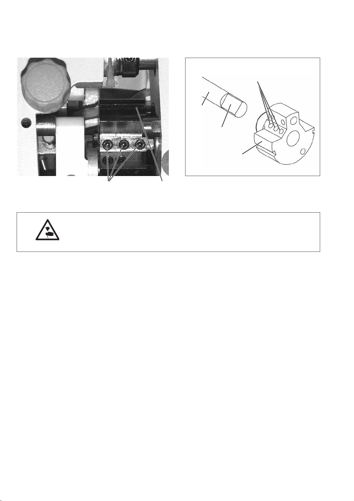
2.6.3 Distance between hook and needle
32 1
Caution: Danger of injury!
Turn off the main switch.
Only check and adjust the hook distance when the machine is
switched off.
4
Standard checking
In the loop stroke position the distance between the hook tip and the
needle channel must be no more than 0.1mm.
Correction
–
Check whether the needle is being pushed away from the hook
guard 6 in the loop stroke position.
If the needle is being pushed away the needle guard must be reset
accordingly (see chapter 2.6.4).
–
Check the distance.
The distance between the needle 4 and the hook should be
no more than 0.1mm.
–
5
Undo screw 1.
–
Undo screw 2.
–
Undo screws on the bevel gear 5.
(Screws can be reached at 202° and 292").
–
Push the hook housing to the side accordingly.
–
Screw in screws 1 and 2 again.
–
Set the loop stroke (see chapter 2.6.1).
–
Place the bevel gear 5 so close that the hook has even less radial
play inside the bevel gears.
–
Replace screws on the bevel gear 5.
22
6
Page 27

2.6.4 Needle guard
21
Caution: Danger of injury!
Turn off the main switch.
Only check and adjust the needle guard when the machine
is switched off.
GB
Standard checking
The needle guard 2 should prevent the needle touching the hook tip.
In the loop stroke position the needle should be pushed away slightly.
–
Check the needle guard.
Correction
–
Turn the machine to the loop stroke position.
–
Adjust the needle guard by turning screw 1.
IMPORTANT!
The needle guard must be adjusted after a change in the needle
bar height, after adjusting the loop stroke and after changing
the needle thickness.
23
Page 28

2.7 Bobbin housing elevator
2.7.1 General
The thread lever must draw the thread between the bobbin housing
and its retainer.
So that the thread can slip through unhindered, the bobbin housing
must be raised at this time.
As a result the required seam construction is achieved with the lowest
possible thread tension.
Incorrect settings may have the following effects:
–
–
–
2.7.2 Bobbin housing elevator path
Thread breaking
Loops on the underside of the seam
Loud noises
1
32
Caution: Danger of injury!
Turn off the main switch.
Only check and adjust the bobbin housing elevator when the
machine is switched off.
Standard checking
The bobbin housing elevator 3 should raise the middle part of the
hook 2 so that the sewing thread can slip through unhindered between
the bobbin housing lug and the throat plate recess.
The elevation gap X depends on the thickness of the thread to be
sewn.
–
Turn the hand wheel and check whether the bobbin housing
elevator opens the bobbin housing far enough.
24
Page 29

2.7.3 Elevation time
21
Correction
–
Turn eccentric bolt 2.
The eccentric bolt 2 is held by the grub screw 1 and a plastic
pressure piece.
–
The frictional force can be changed with grub screw 2 when the
hook bearing is removed.
The time of elevation is firmly preset by the eccentric on the hook and
cannot be changed.
GB
25
Page 30

2.8 Feed foot and material presser foot
2.8.1 Feed foot and material presser foot stroke
21
Caution: Danger of injury!
Turn off the main switch.
Only check and adjust the sewing feet stroke when the machine is
switched off.
Standard checking
The strokes of the t wo sewing feet should be the same height when
the adjustment wheel 5 for the sewing foot stroke setting is set to “3".
–
Set stitch length to “0".
–
Set the average sewing foot pressure.
–
Set the sewing foot stroke on the adjustment wheel 5 to “3".
–
Unscrew t he feed dog.
–
Put a plate (3 mm) under the sewing feet.
–
Turn the hand wheel and compare the strokes of sewing feet 1
and 2.
The stroke of the material presser foot 1 and the feed foot 2
should be the same height.
5
Correction
–
Unscrew the arm cover.
–
Turn the hand wheel to position “0°”.
–
Undo screw 3.
–
Press feeder foot 2 right down onto the throat plate.
–
Tighten screw 3.
–
Screw t he arm cover back on.
–
Turn the adjustment wheel to setting “3".
–
Check whether both strokes are the same height.
If not correct the s etting.
3
26
Page 31

2.8.2 Feed foot stroke movement
21
Caution: Danger of injury!
Turn off the main switch.
Only check and adjust the stroke movement when the machine is
switched off.
Condition
The same sewing foot and material presser foot stroke is set (see
·
chapter 2.8.2)
The time of the feed dog stroke movement is correct (see
·
chapter 2.3.3).
Adjustment
The descending feeder foot 2 should alight on the feed dog at the
maximum sewing foot stroke and a maximum stitch length if, with the
descending needle 1 the needle point has reached the top edge of the
feeder foot (95° on the hand wheel).
–
Set the longest stitch length.
–
Set the maximum sewing foot stroke.
–
Turn the hand wheel and check the stroke movement.
3
GB
Correction
–
Undo the screws on the stroke eccentric 3 (2 screws).
–
Turn the eccentric accordingly.
IMPORTANT!
The eccentric must not be moved axially.
–
Do up the screws on t he stroke eccentric 3.
–
Check the setting.
27
Page 32

2.8.3 Sewing foot pressure
1
Standard checking
The material to be processed must not float.
However, it should not be given any more pressure than necessary.
Correction
–
Set the sewing foot pressure with screw 1.
To increase sewing foot pressure
= Turn screw 1 clockwise.
To reduce sewing foot pressure
= turn screw 1 anti-clockwise.
28
Page 33

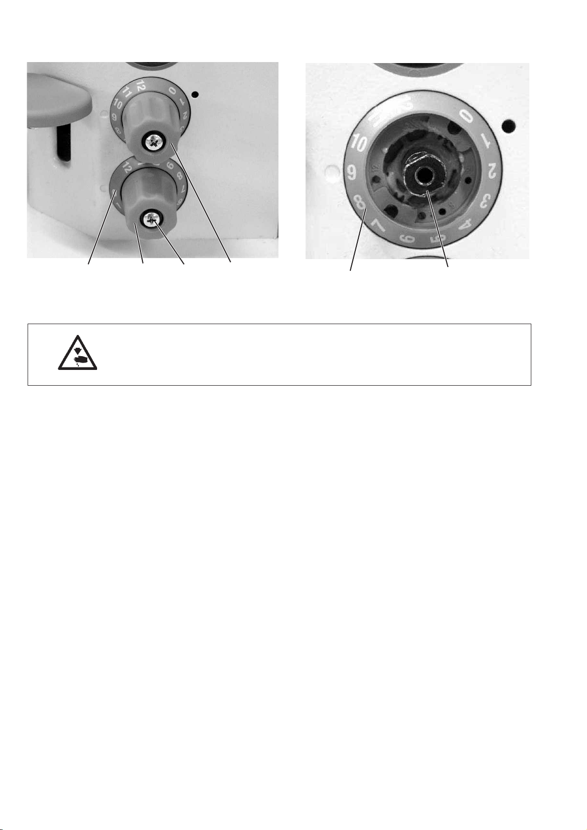
2.9 Stitch length limitation
321
Depending on the sewing equipment used the stitch length setting
must be limited to 6 or 9 mm.
–
Remove screw 2 on the stitch length adjustment wheel.
–
Take out adjustment wheel 1.
–
Unscrew grub screw 4 and screw it into the corresponding hole.
The holes have numbers.
For 6 mm = screw in hole 8
For 9 mm = screw in hole 12
–
Configure a s in chapter 2.3.1 “Basic stitch adjustment setting”.
–
Put the adjusting wheel on and fix with screw 2.
4
GB
29
Page 34

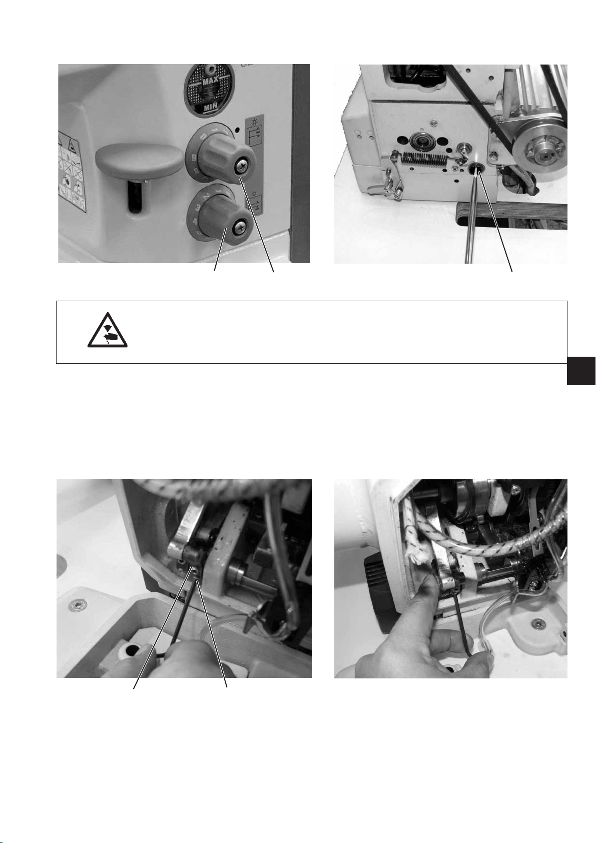
2.10 Consistent forward and reverse stitches
1
Caution: Danger of injury!
Turn off the main switch.
Only set the stitch evenness when the sewing machine is switched off.
Standard checking
The stitch length for the forward and reverse stitch should be the
same.
–
Sew a seam forwards.
–
Sew a seam in reverse.
–
Compare the stitch lengths of the two seams.
Correction
–
Undo screw 3.
–
Turn the eccentric with a screwdriver through hole 1.
Clockwise =
Forward stitch larger, reverse stitch smaller.
32
30
Anti-clockwise =
Reverse stitch larger, forwards stitch smaller.
–
Tighten screw 3.
–
Sew a seam forwards.
–
Sew a seam in reverse.
–
Compare the stitch lengths of the two seams.
Page 35

2.11 Sewing foot lifting
211.1 Sewing foot lifting (mechanical)
12 1
Caution: Danger of injury!
Turn off the main switch.
Only check and adjust the play in the raising mechanism when the
machine is switched off.
Standard checking
The elevating shaft 6 must be smooth running but must not have any
axial play.
The play in the raising mechanism should be about 0.5 mm between
spring guide 2 and the elevating lever 1.
–
Lower sewing feet.
–
Turn the hand wheel until the material pressure foot comes down.
–
Move the elevating shaft 6 and check play.
Correction
Place the elevating shaft close by.
–
Unscrew t he electronic and pneumatic unit 5.
–
Undo the screw on adjustment ring 3.
–
6
Push the elevating shaft completely to the right (see arrow), push
the adjustment ring 3 onto the bearing bush and screw on.
ATTENTION!
The shaft must still run smoothly.
54 3
GB
Elevating shaft play
–
Undo the screws 4 on the elevating pulley.
–
Turn the elevating shaft 6 until there is some play.
–
Do up the screws on the elevating pulley 4.
31
Page 36

2.11.2 Height of the sewing feet locked with the hand lever
1
Caution: Danger of injury!
Turn off the main switch.
Only check and adjust the sewing foot lifting when the machine is
switched off.
Standard checking
The sewing feet 4 are locked into the raised position with hand lever 1
to change the sewing feet, for example, or to run the sewing machine
without material or to wind the hook thread.
The sewing feet 4 locked into the raised position with the hand lever
should be 10 mm away from the throat plate.
–
Bring both sewing feet to the same level.
–
Raise and lock the sewing feet with the hand lever.
–
Check the elevation height.
Correction
–
Raise the sewing feet.
–
Put a spacer (10 mm) under the sewing feet.
–
4
Undo the screws on the elevation lever 3.
–
Press t he elevation lever 1 down.
–
Press lever 3 onto the eccentric disc 2.
–
Do up the screws on t he elevation lever 3.
32
32
Page 37

2.11.3 Height of the raised sewing feet
21
Caution: Danger of injury!
Turn off the main switch.
Only check and adjust the height of the raised sewing feet when the
machine is switched off.
Standard checking
The sewing feet 4 raised pneumatically or by using a knee lever
should be 20 mm from the throat plate when the thread lever is at the
top dead centre.
The screw 2 restricts the passage of the ventilation lever 3.
–
Lower sewing feet.
–
Turn the hand wheel until the thread lever is at the top dead
centre.
–
Raise with the knee lever or pneumatically and measure the
elevation height.
Correction
4
–
Undo the counter nut 1.
–
Turn the stop screw 2 accordingly.
–
Tighten counter screw 1.
3
GB
33
Page 38

2.12 Thread carrying parts
2.12.1 Thread regulator
21
Caution: Danger of injury!
Turn off the main switch.
Only check and adjust the thread regulator when the machine is
switched off.
Standard checking
The position of the thread regulator 1 depends on the thickness of the
material, the thread thickness and the s elected stitch length.
It must be set so that the thread is fed round the hook in a controlled
manner.
The greatest a mount of thread is released at setting “1" as it is
required for particularly long stitch lengths and thick sewing threads.
–
Open the throat plate slide.
–
Thread the needle and hook thread.
–
Insert the material.
–
Start sewing for a short time.
–
Turn the hand wheel and observe how tightly the needle thread is
being fed around the hook.
Correction
–
Undo screw 2.
–
Move the thread regulator.
Thread regulator to the left = more thread
Thread regulator to the right = less thread.
–
Tighten screw 2.
34
Page 39

2.12.2 Thread take up spring
2
3
1
Caution: Danger of injury!
Turn off the main switch.
Only check and adjust the thread take up spring when the machine is
switched off.
Standard checking
The adjustment rules for spring travel and spring tension apply to
normal needle thread thicknesses.
With extremely s trong or weak needle threads or sewing material
other settings may be required.
Spring travel
The thread take up spring 1 must keep the needle thread at low
tension from the top thread level position until the eye of the needle
pierces the material.
To achieve an even seam at low thread tension the thread take up
spring travel can also be increased.
The thread take up spring must only be at the stop when the needle
has penetrated the material up to the eye.
Spring tension
The spring tension should be lower than the needle thread tension.
4
GB
Correction
Spring travel
–
Undo screw 2.
–
Turn the stop sleeve 4.
Turn anti-clockwise = more travel
Turn clockwise = less travel.
–
Tighten screw 2.
Spring tension
–
Undo screw 2.
–
Adjust spring washer 3 without changing the position of the stop
sleeve 4.
Turn the washer clockwise = less spring tension
Turn the washer anti-clockwise = more spring tension.
–
Screw in s crew 2 without turning the position of the stop sleeve 4
and the spring washer 3.
35
Page 40

2.13 Bobbin winder
54321
Caution: Danger of injury!
Turn off the main switch.
Only check and adjust the bobbin winder when the machine is
switched off.
Standard checking
The winding procedure must stop automatically when the bobbin is
filled up to about 0.5 mm below the edge of the bobbin.
The bobbin wheel should have no axial play but must also run
smoothly.
10
9
8
11
Basic settings
–
–
–
–
7
–
–
–
Remove the bobbin winder.
To do this unscrew the two fixing screws 1 and 5 and remove the
bobbin winder.
Screw in s crew 4 until the two side pieces of the bobbin winder
flap 3 are parallel to each other.
Put a completely full bobbin onto the bobbin winder.
Turn the bobbin winder flap so that it rests against the thread on
the bobbin.
Undo screw 7.
Set the cam 11 so that the corner 10 of the cam and the corner 8
of the flat spring 9 are on t op of each other (spring is tensioned)
and the bobbin winder flap 3 has not axial play.
Tighten screw 7.
6
36
Page 41

43121
–
Turn the bobbin winder spindle so that the cutting blade 12 points
towards the right fixing screw 1.
–
Undo the screw on the engaging bracket 14.
–
Adjust the bobbin winder flap so that there is 2 - 3 mm of air
between the thread on the bobbin and the bobbin winder flap
(insert a spacer).
–
Set the engaging bracket 14 so that it is next to the locking
disc 13 and has 0.5 mm of air axially between it and the bobbin
winder wheel 6.
–
Fasten the screw into the engaging bracket.
–
Screw the bobbin winder down again.
Smaller changes to the fill quantity
–
Set the bobbin winder flap 3 with screw 4.
To adjust the bobbin winder pre-tensioning position
The guide must be set so that the bobbin is filled with thread evenly
over its width.
–
Undo screw 17.
–
Set guide 16.
–
Tighten screw 17.
14 13 6
GB
17 16
37
Page 42

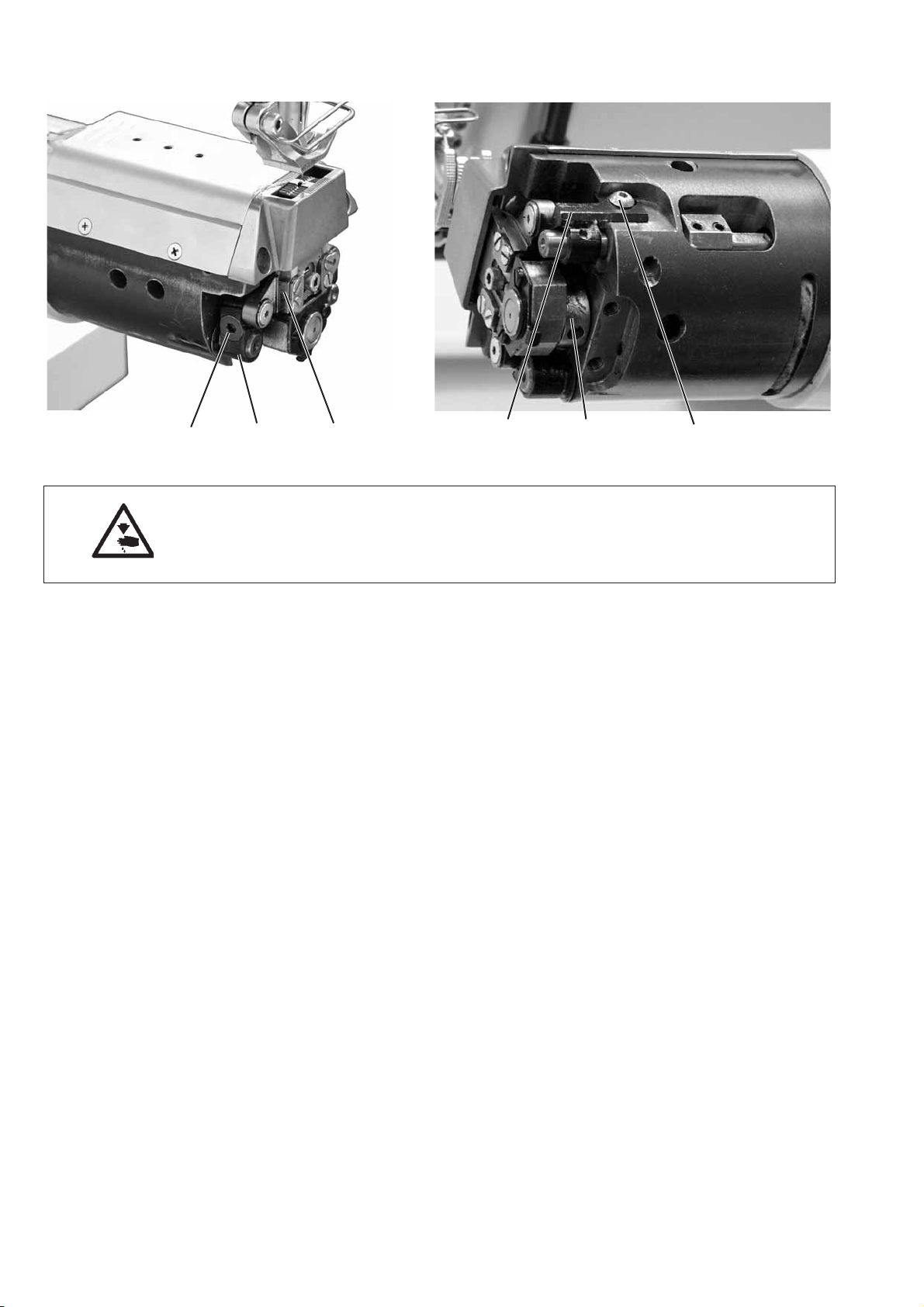
2.14 Thread cutter
2.14.1 Thread pulling knife height
1
3
32 1
Caution: Danger of injury!
Turn off the main switch.
Only check and adjust the thread pulling knife when the machine is
switched off.
Standard checking
The thread pulling k nife should go past the bobbin 3 at a distance of
0.3 mm.
Correction
–
Undo screw 2.
–
Align the height of the thread pulling knife 1.
–
Tighten screw 2.
38
Page 43

2.14.3 Thread pulling knife
21
Caution: Danger of injury!
Turn off the main switch.
Only check and adjust the thread pulling knife when the machine is
switched off.
Standard checking
When the thread pulling knife 1 is in its rest position the distance
between the cam 4 (highest point) and the spool 5 should be 0.1 mm.
Here the cam must be next to the edge of the snap fit coupling 8.
In the rest position the thread pulling knife should be flush with the
edge of the counter blade 2.
–
Check whether the cam is close by.
–
Turn the machine until the highest point of the cam 4 is next to the
spool 5 (80° on the hand wheel).
–
Check the distance between the cam 4 and the spool.
Correction
–
Undoscrews3onthecam4.
–
Put the cam right over to the right.
–
Do up the screws 3 on the cam again.
65 43
GB
–
Undo screw 6.
–
Set a distance of 0.1mm between the cam 4 and the spool 5.
–
Tighten screw 6.
–
Undo screws 7.
–
Turn the thread pulling knife 1 so that it projects 0.2 - 0.8 mm over
the edge of the counter blade.
–
Tighten screws 7.
17
39
Page 44

2.14.4 Cutter pressure and bobbin thread clamp
Caution: Danger of injury!
Turn off the main switch.
Only check and adjust the counter blade and the bobbin thread clamp
when the machine is switched off.
1
Standard checking
The thread should be cut reliably with the lowest possible pressure.
Low cutting pressure keeps wear on the blades low.
Two of the thickest threads to be sewn must be cut reliably at the
same time.
The clamping spring 1 should keep the cut thread so that skipped
stitches do not occur at the start of the seam.
–
Turn the hand wheel until the thread draw cutter can be swung
out.
–
Swing the thread draw cutter out by hand.
–
Insert two of the threads to be cut into the thread draw cutter.
–
Keep turning the hand wheel until the cutter has swung back.
–
Check whether the sewing threads have been cut cleanly.
–
Remove the thread from the clamp and check the clamping effect
while doing this.
If the clamping effect is too great or too small the thread clamp
must be reset.
IMPORTANT!
If the counter cutter pressure is set too high this leads to increased
wear on the cutter.
An incorrect thread clamp setting may lead to problems at the start of
sewing.
40
Page 45

To adjust cutting pressure
321
Adjustment
For a flawless cutting operation it is important for screw 4 in the free
arm to be up against the counter cutter support with a slight pressure
and in this way it cannot be pressed down.
Correction
–
Undo screw 4 a little and then screw it in slightly again on the
counter cutter.
–
Swing the thread draw cutter out until the arrow on the cutter
points towards t he edge of the counter cutter.
–
Undo screw 1.
–
Place the thread draw cutter 2 against the counter cutter.
–
Tighten screw 1.
Important
The eccentric cut of the thread draw cutter 2 automatically produces a
cutting pressure when both cutting edges are on top of each other.
4
GB
41
Page 46

To adjust the bobbin thread clamp
5
–
Unscrew bar 5.
–
Turn screw 6.
Clockwise = clamping force higher
Anti-clockwise = clamping force lower
–
Screwbar5onagain.
6
42
Page 47

2.14.5 Cutting position
1
Caution: Danger of injury!
Turn off the main switch.
Only check and adjust the cutting position when the machine is
switched off.
Standard checking
If the machine is at position 58° on the hand wheel the threads must
be cut.
Correction
–
Undo screws on the cam 1.
–
Turn the cam accordingly.
–
Do up screws on cam 1 .
–
Check whether the threads have been cut at 58° on the hand
wheel.
Note!
Ensure that the cam is on the right.
GB
43
Page 48

2.15 Potentiometer in the arm
Sewing machines with thread cutters are fitted with a potentiometer to
limit the speed with larger sewing foot strokes. The control unit
detects this potentiometer in the sewing foot stroke and restricts the
speed.
21
2.15.1 Basic setting without control panel
Sewing machines without a control panel must be adjusted as
described below.
Caution: Danger of injury!
Turn off the main switch.
Only set the potentiometer when the sewing machine is switched off.
–
Unscrew the arm cover.
–
Remove plug 3 of the potentiometer from c ircuit board 4.
–
Check the resistance on the terminals (2) and (3) of the
potentiometer with an ohmmeter
Terminal (3) = green wire
Terminal (2) = brown wire
Reading: 7.1 - 7.3 kOhm
43
44
(3) (2)
If the above values are not correct the setting of the potentiometer 2
must be corrected.
–
Undo screw 1.
–
Set the shaft of the potentiometer 2 to the corresponding value.
–
Insert the potentiometer completely into the regulating shaft hole
and screw in screw 1.
–
Insert plug 3 of the potentiometer into circuit board 4.
Page 49

2.15.2 Basic setting with V810 or V820 control panel
21
Caution: Danger of injury!
The potentiometer is adjusted when the main switch is on.
Work with appropriate precautions.
–
Undo the locking screw 1 for the potentiometer 2.
–
Press down a nd hold “P” and switch the main switch on.
–
Access the technician level.
–
Select parameter “F-188”.
–
Press “E”.
The current speedomat level (e.g. 11) and the relevant speed limit
(e.g. 2480) are displayed.
–
Turn the potentiometer shaft until speedomat level 07 and the
relevant maximum speed of 2800 rpm are displayed on the screen.
–
Screw in loc k in g screw 1.
–
Check the adjustment.
GB
45
Page 50

2.15.3 Testing the potentiometer adjustment
1
–
Press down a nd hold “P” and switch the main switch on.
–
Access the technician level.
–
Select parameter “F-188”.
–
Press “E”.
The current speedomat level and the relevant speed limit are
displayed.
–
Set the adjusting wheel 1 to “lowest stroke height”.
Speedomat level 06 must be displayed on the screen.
–
Set the adjusting wheel 1 to “maximum stroke height”.
Speedomat level 21 must be displayed on the screen.
“EEEE” appears on the screen for the speed.
Important
If speedomat levels 07 and 21 are not reached the potentiometer must
be reset.
46
Page 51

2.16 Oil lubrication
Caution: Danger of injury!
Oil can cause skin rashes.
Avoid excessive contact with the skin.
Wash thoroughly after contact.
IMPORTANT!
The handling and disposal of mineral oils is subject to legal
regulations.
Deliver used oil to an authorized collecting station.
Protect your environment.
Ensure that you do not spill any oil.
Only use lubrication oil DA 10 or a similar oil with the following
specifications to lubricate the special sewing machine:
–
Viscosity at 40° C: 10 mm²/s
–
Flash point: 150° C
DA 10 can be bought at the sales points of DÜRKOPP ADLER AG
under the following parts numbers:
200 ml container: 9047 000011
1 litre container: 9047 000012
2 litre container: 9047 000013
5 litre container: 9047 000014
GB
1
Lubricating the upper part of the machine
–
The upper part of the machine is fitted with a central oil wick
lubrication system. All bearing points are supplied from the oil
supply container 1.
–
The oil level must not go below the “MIN” mark.
–
Fill with oil up to the “MAX” mark through the hole in the
inspection glass.
47
Page 52

2.17 Maintenance
Caution: Danger of injury!
Switch the main switch off.
The sewing machine must only be maintained when it is switched off.
The maintenance work to be carried out by the sewing machine
operating personnel daily or weekly (cleaning and lubricating) are
described in the operating instructions (Part 1). They are only listed in
the following table for completeness.
Maintenance work to be carried out Operating hours
8 40 160 500
Upper part of sewing machine
-Remove sewingdust andloosethread ............................. X
- Check the oil level in the oil reservoir for lubricating
thetopofthesewingmachine..................................... X
Sewing drive
-Cleanthemotorfangrid.......................................... X
-ChecktheconditionandtensionoftheVbelt....................... X
Pneumatic system
-Checkthewaterlevelinthepressurecontroller..................... X
-Cleanthefilterinsertinthecompressedairmaintenanceunit ........ X
- Checking the pneumatic system for leaks .......................... X
48
 Loading...