


able of Contents
T
1 Introduction
2 General Characteristics
3 Composition and Chemistry
3.1 Active Components: Positive and Negative Electrodes
3.2 Electrolyte
3.3 Cell Reactions
4 Battery Construction
4
.1 Basic Cell Construction
4.2 Cylindrical Cell Construction
4.3 Prismatic Cell Construction
5 Performance Characteristics
5.1 General Characteristics
5.2 Discharge Characteristics: Effect of Discharge Rate
and Temperature
5.3 Capacity: Effect of Discharge Rate
and Temperature
5.4 Energy Density
Ni-MH Rechargeable Batteries
5.5 Constant Power Discharge Characteristics
5.6 Polarity Reversal During Overdischarge
5.7 Internal Impedance
5.8 Self-Discharge and Charge Retention
5.9 Voltage Depression (“Memory Effect”)
6 Charging Sealed Nickel-Metal Hydride Batteries
6.1 General Principles
6.2 Techniques for Charge Control
6.2.1 Timed Charge
6.2.2 Voltage Drop (-∆V)
6.2.3 Voltage Plateau (zero ∆V)
6.2.4 Temperature Cutoff
6.2.5 Delta Temperature Cutoff (∆TCO)
6.2.6 Rate of Temperature Increase (dT/dt)
7 Cycle and Battery Life
7.1 Cycle Life
7.2 Battery Life
8 Safety Considerations
9 Proper Use and Handling
9.1
Care and Handling
9.2 Transportation
9.3 Waste Management: Recycling and Disposal
6.3 Charging Methods
6.3.1 Duracell’s Recommendation:
Three-Step Charge Procedure
6.3.2 Low-Rate Charge
6.3.3 Quick Charge
6.3.4 Fast Charge
6.3.5 Trickle Charge
6.4 Thermal Devices

Ni-MH Rechargeable Batteries
Introduction
1
Rapid advancements in electronic technology have expanded the number of battery-powered portable
devices in recent years, stimulating consumer demand for higher-energy rechargeable batteries capable of
delivering longer service between recharges or battery replacement.
The trend towards smaller, lighter more portable battery-powered devices is expected to continue well
into the future, with the so-called “3C” applications — cellular phones, portable computers and consumer
electronics — expanding rapidly beyond the traditional business user and into the consumer marketplace.
As with other battery-powered consumer devices, battery performance and convenience will influence
the rate of consumer acceptance for 3C devices. Yet conventional rechargeable batteries often fail to meet the
needs of consumers, as well as equipment designers, in terms of their size and weight, operating time, easeof-use, availability and environmental acceptability. New battery systems are needed to meet their growing list
of demands.
The sealed nickel-metal hydride (Ni-MH) battery is one rechargeable battery system that is responding
to these demands by offering significant improvements over conventional rechargeable batteries in terms of
performance and environmental friendliness. First introduced to the commercial market in 1988, nickel-metal
hydride battery technology is at a very early stage of maturity and manufacturers such as Duracell have
identified many opportunities to improve battery performance. These improvements will make DURACELL
nickel-metal hydride batteries an attractive power source for 3C devices for many years to come.
General Characteristics
2
Many of the operating characteristics of the sealed nickel-metal hydride rechargeable battery are similar to those of the sealed nickel-cadmium rechargeable battery. The nickel-metal hydride battery, however, has
the advantage of higher energy density (or capacity) which translates into longer service life. In addition, the
nickel-metal hydride battery is environmentally friendlier than nickel-cadmium and other battery systems
because it contains no added cadmium, mercury or lead.
Features of the sealed nickel-metal hydride battery include:
Higher capacity — Up to 40 percent longer service
•
life than ordinary nickel-cadmium batteries of
equivalent size.
High rate discharge — Efficient discharge at rates
•
as high as 2C.
Fast charge — Can be charged in approximately
•
one hour.
Safe — Designed to safely withstand abusive
•
conditions in consumer devices.
Long cycle life — Up to 500 charge/discharge cycles.
•
Performs at extreme temperatures — Capable of
•
operation on discharge from -20°C to 50°C (-4°Fto
122°F) and charge from 0°C to 45°C (32°F to
113°F).
Environmentally friendlier than nickel-cadmium
•
batteries — Zero percent cadmium.
Similar operating voltage to nickel-cadmium
•
batteries — Allows user to upgrade easily to longer
lasting nickel-metal hydride batteries.
1
Ni-MH Rechargeable Batteries
Composition and Chemistry
3
A rechargeable battery is based on the principle that the charge/discharge process is reversible, that is, the
energy delivered by the battery during discharge can be replaced or restored by recharging.
3.1 Active Components: Positive and Negative Electrodes
Nickel oxyhydroxide (NiOOH) is the active material in the positive electrode of the nickel-metal hydride
battery in the charged state, the same as in the nickelcadmium battery.
The negative active material, in the charged state,
is hydrogen in the form of a metal hydride. This metal
alloy is capable of undergoing a reversible hydrogen
absorbing/desorbing reaction as the battery is charged
and discharged, respectively.
The unique attribute of the hydrogen storage
alloy is its ability to store hundreds of times its own
volume of hydrogen gas at a pressure less than atmospheric pressure. Many different intermetallic compounds have been evaluated as electrode materials for
nickel-metal hydride batteries. Typically, these fall into
two classes: AB
alloys, of which LaNi5is an example,
5
3.2 Electrolyte
An aqueous solution of potassium hydroxide is
the major component of the electrolyte of a nickelmetal hydride battery. A minimum amount of electrolyte is used in this sealed cell design, with most of
and AB
ogy is based on the use of AB
AB
tics, resulting in longer cycle life and better rechargeability following storage. The composition of the metal
alloy is formulated for optimal stability over a large
number of charge/discharge cycles. Other important
properties of the alloy include:
this liquid being absorbed by the separator and the
electrodes. This “starved electrolyte” design facilitates
the diffusion of oxygen to the negative electrode at the
end-of-charge for the “oxygen recombination” reaction.
alloys, of which TiMn2or ZrMn2are examples.
2
DURACELL nickel-metal hydride battery technol-
instead of AB2alloys.
5
alloys offer better corrosion resistance characteris-
5
Large hydrogen storage capability for high energy
•
density and battery capacity.
Favorable kinetic properties for high rate capability
•
during charge and discharge.
Low hydrogen pressure alloy and high purity mate-
•
rials to minimize self-discharge.
3.3 Cell Reactions
During discharge, the nickel oxyhydroxide is
reduced to nickel hydroxide
NiOOH + H
and the metal hydride (MH) is oxidized to the metal
alloy (M).
MH + OH-——> M + H
O + e-——> Ni(OH)2+ OH
2
O + e
2
-
-
The overall reaction on discharge is:
MH + NiOOH ——> M + Ni(OH)
The process is reversed during charge.
2
2
Composition and Chemistry (cont.)
Ni-MH Rechargeable Batteries
The sealed nickel-metal hydride cell uses the
“oxygen-recombination” mechanism to prevent a buildup of pressure that may result from the generation of
oxygen towards the end of charge and overcharge.
This mechanism requires the use of a negative electrode
(the metal hydride/metal electrode) which has a higher
effective capacity than the positive (nickel oxyhydroxide/nickel hydroxide electrode) electrode. A schematic
drawing of the electrodes is shown in Figure 3.3.1.
During charge, the positive electrode reaches
full charge before the negative electrode which causes
the evolution of oxygen to begin:
2OH
- _____
> H
O +
2
1
O2+ 2e
2
-
The oxygen gas diffuses through the separator
to the negative electrode, a process which is facilitated
by the “starved-electrolyte” design and the selection of
an appropriate separator system.
At the negative electrode, the oxygen reacts
with the metal hydride and oxidizes or discharges the
metal hydride to produce water:
FIGURE 3.3.1
Positive Electrode
NiOOH/Ni(OH)
Useful Capacity
MH/Alloy
Charge
Reserve
Schematic representation of the electrodes, divided
into useful capacity, charge reserve and discharge
reserve.
Negative Electrode
2
Discharge
Reserve
2MH +
O
2
2
> 2M + H
O
2
1
_____
Thus, the negative electrode does not become fully
charged and pressure does not build up.
The charge current, however, must be controlled at the end of charge and during overcharge to
limit the generation of oxygen to below the rate of
recombination. Thus, charge control is required to prevent the build-up of gases and pressure. Duracell recommends that continuous overcharge not exceed C/300
for optimal performance.
As shown in Figure 3.3.1, the nickel-metal
hydride cell is designed with a discharge and charge
reserve in the negative electrode. The discharge
reserve minimizes gassing and degradation of the cell in
the event of overdischarge. The charge reserve ensures
that the cell maintains low internal pressure on overcharge.
The negative electrode has excess capacity
compared to the positive electrode and is used to
handle both overcharge and overdischarge. Thus,
the useful capacity of the battery is determined by
the positive electrode.
3
Ni-MH Rechargeable Batteries
Battery Construction
4
DURACELL standard-sized nickel-metal hydride batteries are constructed with cylindrical and prismatic nickelmetal hydride cells. DURACELL nickel-metal hydride batteries are a sealed construction designed for optimal performance and maximum safety. The batteries are manufactured to strict quality control standards to ensure reliability
and consumer satisfaction and offer such features as:
High energy density — Minimizes battery volume
•
and weight
Wide voltage range — Meets operating voltage
•
requirements of 3C devices
Thin profiles — Innovative wall-less design
•
Advanced interconnect — Self securing, voltage-
•
keyed interconnect provides a highly reliable batteryto-device contact
4.1 Basic Cell Construction
The electrodes in both cylindrical and prismatic
cell configurations are designed with highly porous
structures which have large surface areas to provide low
internal resistance which results in superior high rate
performance. The positive electrode in the cylindrical
4.2 Cylindrical Cell Construction
The assembly of a cylindrical cell is shown in
Figure 4.2.1. The electrodes are separated by the separator which is a synthetic, non-woven material that
serves as an insulator between the two electrodes and as
a medium for absorbing the electrolyte. The electrodes
are spirally-wound and inserted into a cylindrical nickelplated steel can. The electrolyte is added and contained
within the pores of the electrodes and separator.
The positive electrode is connected to the metal
lid with a tab. The cell is then sealed by crimping the
Durability — Manufactured with LEXAN®and
•
LUSTRAN
retardant polymers
UL listing — Independent approval of battery use
•
in devices
nickel-metal hydride cell is a highly porous nickel-felt
substrate into whichthe nickel compounds are pasted.
Similarly, the negative electrode is a perforated nickelplated steel foil onto which the plastic-bonded, active
hydrogen storage alloy is coated.
top assembly to the can. The top assembly incorporates
a resealable safety vent, a metal lid and a plastic gasket.
A heat-shrink tube is placed over the metal can. The
bottom of the metal can serves as the negative terminal
and the metal lid as the positive terminal. The insulator
and gasket insulate the terminals from each other. The
vent provides additional safety by releasing any excess
pressure that may build up if the battery is subjected to
abusive conditions.
®
polycarbonate high impact and flame
LEXAN®is a registered trademark of the General Electric Company.
LUSTRAN®is a registered trademark of the Monsanto Company.
FIGURE 4.2.1
Safety Vent
(+) Positive Terminal
Metal Can
Separator
Negative Electrode
Heat Shrink Tube
Positive Electrode
(-) Negative Terminal
Insulator
Positive Tab
Metal Lid
Cosmetic Disk
Gasket
4
Battery Construction (cont.)
Ni-MH Rechargeable Batteries
4.3 Prismatic Cell Construction
The basic differences between the prismatic
c
ell and the cylindrical cell are the
the electrodes and the shape of the
cells are designed to meet the needs
equipment where space for the battery is
The rectangular shape of the prismatic cell
more efficient battery assembly by eliminating
voids that occur in a battery constructed with
cylindrical cells. Thus, the volumetric energy density
of a battery can be increased by constructing it with
prismatic instead of cylindrical cells.
Figure 4.3.1 shows the structure of the pris-
matic nickel-metal hydride cell. The electrodes are
manufactured in a manner similar to those of the
cylindrical cell, except that the finished electrodes are
flat and rectangular in shape. The positive and
negative electrodes are interspaced by separator
sheets. The assembly is then placed in a nickel-plated
steel can and the electrolyte is added. The positive
electrodes are connected to the metal lid with a tab.
The cell is then sealed by crimping the top assembly to
the can. The top assembly incorporates a resealable
safety vent, a metal lid and a plastic gasket that is
similar to the one used in the cylindrical cell. A heatshrink tube is placed over the metal can. The bottom
of the metal can serves as the negative terminal and
the top metal lid as the positive terminal. The insulator and gasket insulate the terminals from each
other. The vent provides additional safety by releasing any excess pressure that may build up if the
battery is subjected to abusive conditions.
construction of
can. Prismatic
of compact
limited.
permits
the
FIGURE 4.3.1
Cosmetic
Disk
Gasket
Insulator
Positive Tab
Positive Electrode
Separator
Negative Electrode
Metal Lid
(+) Positive Terminal
Safety Vent
Heat Shrink Tube
(-) Negative Terminal
5
5
Ni-MH Rechargeable Batteries
Performance Characteristics
5.1 General Characteristics
The discharge characteristics of the nickel-metal
hydride cell are very similar to those of the nickelcadmium cell. The charged open circuit voltage of both
systems ranges from 1.25 to 1.35 volts per cell. On
discharge, the nominal voltage is 1.2 volts per cell and
the typical end voltage is 1.0 volt per cell.
Figure 5.1.1 illustrates the discharge characteristics of nickel-metal hydride and nickel-cadmium
rechargeable cells of the same size. As shown, the voltage profile of both types of cells is flat throughout most
of the discharge. The midpoint voltage can range from
1.25 to 1.1 volts per cell, depending on the discharge
load. Figure 5.1.1 can also be used to compare the
capacity of the two rechargeable types. Note that the
capacity of the nickel-metal hydride cell is typically up to
40 percent higher than that of a nickel-cadmium cell of
equivalent size.
FIGURE 5.1.1
1.5
1.4
1.3
1.2
1.1
Voltage (V)
1.0
.9
0 20 40 60 80 100 120 140 160
Ampere-Hour Capacity (%)
Comparison of discharge voltage and capacity of
same-size Ni-MH and Ni-Cd cells.
[Conditions: Charge: C/3 for 5 hours, Temperature: 21°C (70°F)]
C/5
Ni-Cd
C/5
Ni-MH
5.2 Discharge Characteristics: Effect of
Discharge Rate and Temperature
Typical discharge curves for DURACELL nickel-
metal hydride batteries under constant current loads at
various temperatures are shown in Figures 5.2.1 to
5.2.3. Discharge voltage is dependent on discharge
current and discharge temperature.
FIGURE 5.2.1
8.5
8.0
7.5
7.0
Voltage (V)
6.5
6.0
5.5
0 0.5 1.0 1.5 2.0 2.5
FIGURE 5.2.2
8.5
8.0
7.5
7.0
Voltage (V)
6.5
6.0
5.5
0 0.5 1.0 1.5 2.0 2.5
Discharge Capacity (Ah)
Discharge Capacity (Ah)
Temperature: 45°C (113°F)
C (2.4A)
Temperature: 21°C (70°F)
C (2.4A)
FIGURE 5.2.3
8.5
8.0
7.5
7.0
Voltage (V)
6.5
6.0
5.5
0 0.5 1.0 1.5 2.0 2.5
Voltage and capacity of DURACELL DR30 Ni-MH
batteries at various discharge temperatures
and rates.
[Conditions: Charge: 1C to -∆V = 60mV @ 21°C (70°F)]
C/5 (0.48A)
C (2.4A)
C (2.4A)
Temperature: -20°C (-4°F)
Temperature: 0°C (32°F)
C/5 (0.48A)
C (2.4A)
Discharge Capacity (Ah)
C/5 (0.48A)
C/5 (0.48A)
6

Performance Characteristics (cont.)
Ni-MH Rechargeable Batteries
Typically, when the current is higher and the
temperature is lower, the operating voltage will be
lower. This is due to the higher “IR” drop that
occurs with increasing current and the cell’s increasing resistance at the lower temperatures. However,
at moderate discharge rates (≈C/5), the effect of
low temperature on the capacity of the nickel-metal
hydride battery is minimal.
5.3 Capacity: Effect of Discharge Rate
and Temperature
The ampere-hour capacity of the battery is
dependent on the discharge current and temperature,
as can be observed in Figure 5.3.1. It should be noted
that the delivered capacity is dependent on the cutoff
or end voltage. The delivered capacity can be increased
by continuing the discharge to lower end voltages.
However, the battery should not be discharged to too
low a cut-off voltage (less than 0.9 volts per cell) as
the cells may be damaged (see Section 5.6). The
recommended cutoff voltage for nickel-metal hydride
batteries is 1.0 volt per cell.
Typically, optimum performance of the nickelmetal hydride battery is obtained between 0°C and 45°C
(32°F and 113°F). The performance characteristics of
the battery are affected moderately at higher temperatures. At lower discharge temperatures, performance
decreases more significantly, caused primarily by the
increase in internal resistance. Similarly, the effects of
temperature on performance are more pronounced at
higher discharge rates. The capacity of the battery
decreases more noticeably as the current increases,
particularly at lower temperatures.
FIGURE 5.3.1
2.5
2.0
1.5
1.0
Capacity (Ah)
0.5
0
C/5 (0.48)
Discharge Rate (A)
Typical capacity of DURACELL DR30 batteries under
constant current discharges at various temperatures.
[Conditions: Charge: 1C to -∆V = 60mV @ 21°C (70°F); Discharge
to 6.0V]
C (2.4)
°C (70°F)
21
45°C (113°F)
0°C (32°F)
-20°C (-4°F)
2C (4.8)
5.4 Energy Density
Energy density is the ratio of the energy available
from a battery to its volume or weight. A comparison of
the performance of various battery systems is normally
made on practical, delivered energy density per-unitweight or volume using production-based batteries and
performance as opposed to theoretical energy density.
Comparing energy densities, one must consider the
influence of cell size, internal design, discharge rate and
temperature conditions, as these parameters strongly
impact performance characteristics.
7

Performance Characteristics (cont.)
Ni-MH Rechargeable Batteries
Figure 5.4.1 compares the gravimetric and
volumetric energy density of nickel-metal hydride
and nickel-cadmium cells. As indicated, nickel-metal
hydride cells deliver more energy per weight or
volume than nickel-cadmium cells.
5.5 Constant Power Discharge Characteristics
The output energy characteristic of nickel-metal
hydride batteries under the constant power mode at
different power levels is shown in Figure 5.5.1.
As illustrated, the energy delivered does not vary
significantly with increasing power. The power levels
are shown on the basis of E-Rate. The E-Rate is
calculated in a manner similar to calculating the C-Rate.
For example, at the E/10 power level, the power
for a battery rated at 17.3 watt-hours is 1.73 watts.
5.6 Polarity Reversal During Overdischarge
When cells are connected in series, the cell
with the lowest capacity will reach a lower point of
discharge than the others. The more cells that are
connected in series, the greater the possibility of a cell
being fully discharged and driven into overdischarge
and polarity reversal. During reversal, hydrogen gas
evolves from the positive electrode. Hydrogen gas
will be reabsorbed by the negative electrode and
eventually oxygen gas will evolve from the negative
electrode. Extended overdischarge will lead to elevated
cell pressure and opening of the safety vent within
the nickel-metal hydride cells.
To minimize the occurrence of polarity reversal,
the cells in DURACELL rechargeable batteries have
capacities that are “matched” to each other. Device
designers can help prevent overdischarge by designing a
cutoff voltage for device operation of 1.0 volt per cell.
FIGURE 5.4.1
200
150
100
50
Wh/kg
0
Gravimetric and volumetric energy density of Ni-Cd
and Ni-MH cells.
Wh/L
Wh/kg
Ni-Cd Ni-MH
FIGURE 5.5.1
20
15
10
Energy (Wh)
5
0
E/10 (1.7)
Typical energy of DURACELL DR30 batteries under
constant power discharges.
[Conditions: Charge: 1C to -∆V = 60mV; Discharge to 6.0V;
Temperature: 21°C (70°F)]
Power (W)
Wh/L
E (17.3)E/3 (5.8)
8

Performance Characteristics (cont.)
Ni-MH Rechargeable Batteries
5.7 Internal Impedance
DURACELL nickel-metal hydride batteries have low
internal impedance because they are manufactured using
cells designed with thin plate electrodes which offer large
surface areas and good conductivity. Figure 5.7.1 shows
the change in internal impedance with depth of discharge.
As demonstrated, the impedance remains relatively constant
during most of the discharge. Towards the end of the discharge, the impedance increases due to the conversion of
the active materials to a non-conductive form.
5.8 Self-Discharge and Charge Retention
The state-of-charge and capacity of the nickelmetal hydride battery decrease during storage due to
self-discharge of the cells. Self-discharge results from
the reaction of residual hydrogen in the battery with the
positive electrode, as well as the slow and reversible
decomposition of the positive electrode. The rate of
self-discharge is dependent upon the length of time and
temperature at which the battery is stored — the higher the temperature, the greater the rate of self-discharge. As illustrated in Figure 5.8.1, cells stored at
0°C (32°F) retain more of their capacity than those
stored at 20°C and 45°C (68°F and 113°F), particularly
after 30 days.
Generally, long term storage of a nickel-metal
hydride battery in either a charged or discharged condition has no permanent effect on capacity. Capacity loss
due to self-discharge is reversible and nickel-metal
hydride batteries can recover to full capacity by proper
recharging. For example, full capacity of a nickel-metal
hydride battery that was stored at room temperature
for up to one year can be restored by cycling through
repeated charge/discharge cycles.
As with operation at elevated temperatures,
however, long term storage at high temperatures can
lead to deterioration of seals and separators and should
be avoided. The recommended temperature range for
long term storage of nickel-metal hydride batteries is
10°C to 30°C (50°F to 86°F).
FIGURE 5.7.1
180
)
Ω
175
DR30
170
Internal Impedance (m
165
0 20 40 60 80 100
Discharge Capacity (%)
Internal impedance of DURACELL DR30 Ni-MH
batteries at various discharge capacities.
[Conditions: Charge: C/5 for 7.5 hours; Discharge: C/5;
Temperature: 21°C (70°F); Measurements at 1000 Hz]
FIGURE 5.8.1
10 0
80
60
40
Residual Capacity (%)
20
0
0 5 10 15 20 25 30
Self-discharge characteristic of Ni-MH cells at
various temperatures.
[Conditions: Charge: C/3 for 5 hours; Discharge: C/5 to 1.0V;
Temperature: 21°C (70°F)]
Storage Time (Days)
0°C (32°F)
20°C (68°F)
45°C (113°F)
9

Performance Characteristics (cont.)
Ni-MH Rechargeable Batteries
5.9 Voltage Depression (“Memory Effect”)
Although many years of premium performance
can be enjoyed from a nickel-metal hydride battery that
is properly handled, the capacity delivered in each
charge/discharge cycle will eventually begin to decrease.
This inevitable decrease in capacity can be accelerated by
overcharging, storage or usage at high temperatures, or
through poor matching of cells within a pack. Often,
battery users who experience short service life have
incorrectly attributed capacity loss to a phenomenon
called “memory effect.”
The term memory effect is used synonymously with the term “voltage depression.” Voltage
depression is a scientifically measurable characteristic of
all batteries, however, nickel-cadmium batteries demonstrate particularly acute sensitivity. A properly designed
application with nickel-metal hydride batteries will result
in neither permanent performance loss nor perceivable
temporary capacity decreases from this characteristic.
A reversible drop in voltage and loss of capacity
may occur when a nickel-metal hydride battery is partially discharged and recharged repetitively without the
benefit of a full discharge, as illustrated in Figure 5.9.1.
After an initial full discharge (Cycle #1) and charge, the
cell is partially discharged to 1.15 volts and recharged
for a number of cycles. During this cycling, the discharge voltage and capacity drop gradually in very small
increments (Cycles #2 to #18). On a subsequent full
discharge (Cycle #19), the discharge voltage is
depressed compared to the original full discharge
(Cycle #1).
Because the cell appears to “remember” the
lower capacity, this voltage depression phenomenon is
often referred to as memory effect. However, the cell
can be quickly restored to full capacity with a few full
discharge/charge cycles, as indicated in Cycles #20
and #21.
The voltage drop occurs because only a portion
of the active materials in the cell is discharged and
recharged during shallow or partial discharging. The
active materials that have not been cycled change in
FIGURE 5.9.1
1.35
1.25
1.15
1.05
Voltage (V)
0.95
0.85
0 0.2 5 0.5 0.75 1.0
Time (Hours)
Effects on Ni-MH cell capacity due to repetitive partial
discharges.
[Conditions: Charge: (Cycle #1– #21) = 1C to -∆V = 12mV. Discharge: Cycle #1 = 1C
to 1.0 V, (Cycle #2– #18) = 1C to 1.15V, (Cycle #19 – #21) = 1C to 1.0V; Temperature:
21°C (70°F)]
Cycle #2
Cycle #18
Cycle #20
Cycle #19
physical characteristics and increase in resistance.
Subsequent full discharge/charge cycling will restore the
active materials to their original state.
The extent of voltage depression and capacity
loss depends on depth of discharge and can be avoided by
discharging the battery to an appropriate cutoff
voltage. Voltage depression is most apparent when the
discharge is terminated at higher cutoff voltages, such as
1.2 volts per cell. A smaller voltage depression and
capacity loss occurs if the discharge is cut off between
1.15 volts to 1.10 volts per cell. Discharging to 1.0
volts per cell should not result in significant voltage
depression or capacity loss during subsequent discharges.
A device properly designed with nickel-metal
hydride batteries will minimize the effects of voltage
depression and capacity loss. The voltage depression
and capacity loss in DURACELL nickel-metal hydride
batteries is only a small fraction (less than 5 percent
in worst cases) of the battery’s capacity and most users
will never experience a perceptible performance loss.
Cycle #1
Cycle #21
10

6
Ni-MH Rechargeable Batteries
Charging Sealed Nickel-Metal Hydride Batteries
6.1 General Principles
Recharging is the process of replacing energy
that has been discharged from the battery. The subsequent performance of the battery, as well as its overall
life, is dependent on effective charging. The main criteria for effective charging are:
Choosing the appropriate rate
•
Limiting the temperature
•
Selecting the appropriate termination technique
•
The recharging characteristics of nickel-metal
hydride batteries are generally similar to those of
nickel-cadmium batteries. There are some distinct
differences, however, particularly on the requirements
for charge control because the nickel-metal hydride
battery is more sensitive to overcharging. Caution
should be exercised before using a nickel-cadmium
battery charger interchangeably for both battery types
because it may not optimally charge a nickel-metal
hydride battery, particularly on high rate chargers.
The most common charging method for the
nickel-metal hydride battery is a constant current
charge with the current limited in order to avoid an
excessive rise in temperature. Limiting the charge
current also reduces the risk of exceeding the rate of
the oxygen recombination reaction to prevent cell
venting.
Figure 6.1.1 compares the voltage profiles of
nickel-metal hydride and nickel-cadmium batteries during charge at a constant current rate. The voltages of
both systems rise as the batteries accept the charge. As
the batteries approach 75 to 80 percent charge, the
voltages of both battery types rise more sharply due to
the generation of oxygen at the positive electrode.
However, as the batteries go into overcharge, the voltage profile of the nickel-metal hydride battery does not
exhibit as prominent a voltage drop as the nickelcadmium battery.
In Figure 6.1.2, the temperature profiles of the
nickel-metal hydride and nickel-cadmium batteries are
compared during charge at a constant current charge
rate. Throughout the first 80 percent of charge, the
temperature of the nickel-cadmium battery rises gradually because its charge reaction is endothermic (absorbs
heat). The temperature of the nickel-metal hydride
FIGURE 6.1.1
2.0
1.8
1.6
1.4
Voltage /Cell (V)
1.2
1.0
0 20 40 60 80 100 120
Charge Input (% of Typical Capacity)
Typical charge voltage characteristics of Ni-MH and
Ni-Cd batteries.
[Conditions: Charge: 1C @ 21°C (70°F) to -∆V = 10mV/cell]
FIGURE 6.1.2
55
50
45
C)
°
40
35
30
25
Temperature (
20
15
0 20 40 60 80 100 120
Charge Input (% of Typical Capacity)
Typical charge temperature characteristics of Ni-MH
and Ni-Cd batteries.
[Conditions: Charge: 1C @ 21°C (70°F) to -∆V = 10mV/cell]
Ni-Cd
Ni-MH
Ni-MH
Ni-MH
Temperature (°F)
131
122
113
104
Ni-Cd
battery, on the other hand, rises quickly because its
charge reaction is exothermic (releases heat). After
80 to 85 percent of charge, the temperature of both
battery types also rises due to the exothermic oxygen
recombination reaction, causing the voltage to drop as
the batteries reach full charge and go into overcharge.
Both the voltage drop after peaking (-∆V) and
the temperature rise are used as methods to terminate
the charge. Thus, while similar charge techniques can
be used for nickel-metal hydride and nickel-cadmium
batteries, the conditions to terminate the charge may
differ because of the varying behavior of the two battery systems during charge. To properly terminate
charging of DURACELL nickel-metal hydride batteries,
95
86
77
68
59
11

Ni-MH Rechargeable Batteries
Charging Sealed Nickel-Metal Hydride Batteries (cont.)
Duracell recommends the charge termination method
described in Section 6.3.1.
The voltage of the nickel-metal hydride battery
during charge depends on a number of conditions,
including charge current and temperature. Figures
6.1.3 and 6.1.4 show the voltage profile of the nickelmetal hydride battery at different ambient temperatures
and charge rates, respectively. The battery voltage rises
with an increase in charge current due to an increase in
the “IR” drop and overpotential during the electrode
reaction. The battery voltage decreases with increasing
temperature as the internal resistance and overpotential
during the electrode reaction decrease.
A rise in temperature and pressure at high
charge rates occurs and underscores the need for proper charge control and effective charge termination
when “fast charging.” Excessive pressure and temperature increases can result in activation of cell vents or
battery safety electronics, as described in Section 6.4.
Temperature also affects charge efficiency.
Charge efficiency decreases at higher temperatures due
to the increasing evolution of oxygen at the positive
electrode. Thus, charging at high temperatures results
in lower capacity. At lower temperatures, charge efficiency is high due to decreasing oxygen evolution.
However, oxygen recombination is slower at lower temperatures and a rise in internal cell pressure may occur
depending on the charge rate.
Proper charging is critical not only to obtain
maximum capacity on subsequent discharges but also
to avoid high internal temperatures, excessive overcharge and other conditions which could adversely
affect battery life.
6.2 Techniques for Charge Control
FIGURE 6.1.3
10.0
9.5
9.0
8.5
Voltage (V)
8.0
7.5
0 0.2 0.4 0.6 0.8 1.0 1.2
Charge voltage of DURACELL DR30 Ni-MH batteries
at various temperatures.
[Conditions: Discharge: C/5 to 6.0V @ 21°C (70°F); Charge: 1C to -∆V =
60mV]
FIGURE 6.1.4
10.0
9.5
9.0
8.5
8.0
Voltage (V)
7.5
7.0
0 1.0 2.0 3.0 4.0
Charge voltage of DURACELL DR30 Ni-MH batteries
at various rates.
[Conditions: Discharge: C/5 to 6.0V; Charge: 1C to -∆V = 60mV, C/5 to
7.5 hrs.; Temperature: 21°C (70°F)]
0°C (32° F)
21
°C (70° F)
Charge Time (Hours)
Charge Capacity (Ah)
C (2.4A)
C/5 (0.48A)
The characteristics of the nickel-metal hydride
battery define the need for proper charge control in
order to terminate the charge and prevent overcharging
or exposure to high temperatures. Each charge control
technique has its advantages and disadvantages. For
example, higher capacity levels are achieved with a 150
percent charge input, but at the expense of cycle life;
long cycle life is attained with a 105 to 110 percent
charge input, albeit with slightly lower capacity due to
less charge input. Thermal cutoff charge control may
reduce cycle life because higher temperatures are
reached during the charge; however, it is useful as a
backup control in the event that the primary termination method is not effective during charge.
12

Ni-MH Rechargeable Batteries
Charging Sealed Nickel-Metal Hydride Batteries (cont.)
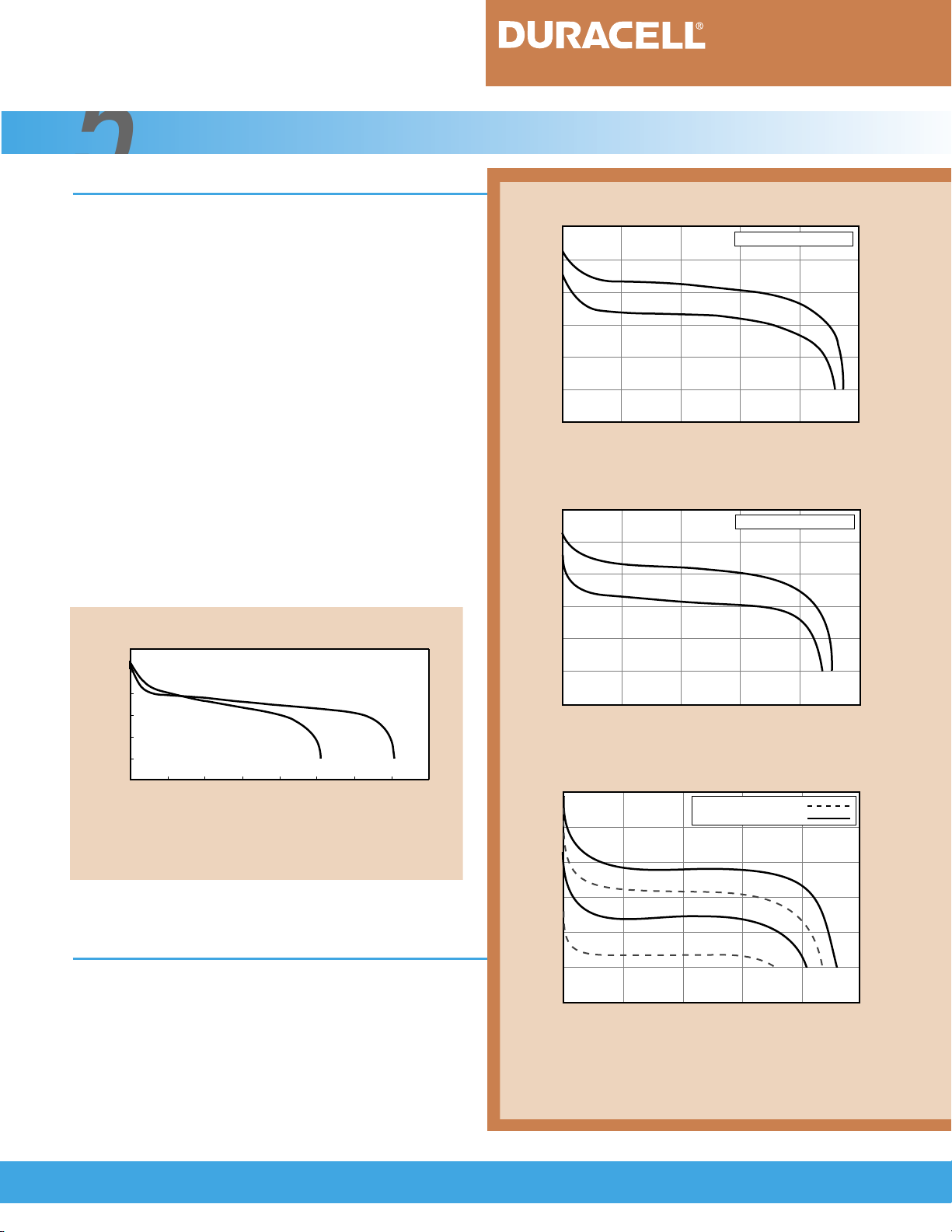
The following summary explains some of the
recommended methods for charge control. The characteristics of each of these methods are illustrated in
Figure 6.2.1. In many cases, several methods are
employed, particularly for high rate charging.
FIGURE 6.2.1
Voltage (V)
-∆V
6.2.1 Timed Charge
Under the timed charge control method, the
charge is terminated after the battery is charged for a
predetermined length of time. This method should be
used only for charging at low rates (less than C/3) to
avoid excessive overcharge because the state-of-charge
of the battery, prior to charging, cannot always be
determined. If a timed charge termination is used, a
time of 120 percent charge input is recommended with
a backup temperature cutoff of 60°C (140°F).
Voltage drop is widely used with nickel-cadmi-
batteries. With this technique, the voltage during
um
charge is monitored and the charge is terminated
when the voltage begins to decrease. This approach
can be used with nickel-metal hydride batteries, but
as noted in Section 6.1, the voltage drop of the nickelmetal hydride battery is not as prominent as that of
the nickel-cadmium battery and may be absent in
charge currents below the C/3 rate, particularly at
elevated temperatures. The voltage sensing circuitry
TCO
Voltage (V)
Temperature (T)
dT/dt
Temperature Differential Output (
Charge Time (t)
Charge characteristics of Ni-MH batteries using
various charge termination methods.
dT/dt)
must be sensitive enough to terminate the charge
when the voltage drops, but not so sensitive that it
will terminate prematurely due to noise or other
normal voltage fluctuations. A charge rate of 1C and
a 5 to 10 millivolt per cell drop is recommended for
the nickel-metal hydride battery with a backup temperature cutoff of 60°C (140°F). A top-up charge is
not necessary with this charge termination method.
)
dT/dt
(
Temperature (T)
Temperature Differential
13
6.2. 3 Voltage Plateau (Zero ∆V)
Since the nickel-metal hydride battery does
not always show an adequate voltage drop, an alternate method used is to terminate the charge when
the voltage peaks and the slope is zero, rather than
waiting for the voltage to drop. The risk of over-
6.2. 4 Temperature Cutoff
Another technique for charge control is to
monitor the temperature rise of the battery and terminate the charge when the battery has reached a
temperature which indicates the beginning of overcharge. It is difficult, however, to precisely determine
charge is reduced as compared to the -∆V method.
If this method is employed, a charge rate of 1C and a
backup temperature cutoff of 60°C (140°F) is recommended. A top-up charge can follow to ensure a full
charge.
Duracell does not recommend this termina-
tion method because of the risk of premature cutoff.
this point because it is influenced by ambient temperature, cell and battery design,
factors. A cold battery, for
charge rate, and other
instance, may be overcharged before reaching the cutoff temperature, while
a warm battery may be undercharged.

Ni-MH Rechargeable Batteries
Charging Sealed Nickel-Metal Hydride Batteries (cont.)
6.2.4 Temperature Cutoff (cont.)
Usually this method is used in conjunction with
other charge control techniques primarily to terminate
the charge in the event that the battery reaches excessive temperatures before the other charge controls
6.2. 5 Delta Temperature Cutoff (∆TCO)
This technique measures the battery temperature rise above the starting temperature during charging
and terminates the charge when this rise exceeds a predetermined value. In this way, the influence of ambient
temperature is minimized. The cutoff value is dependent on several factors, including cell size, configuration
and number of cells in the battery, and the heat capacity
of the battery. Therefore, the cutoff value should be
6.2. 6 Rate of Temperature Increase (dT/dt)
In this method, the change in temperature with
time is monitored and the charge is terminated when a
predetermined rate of temperature rise is reached. The
influence of ambient temperature is reduced. A dT/dt cutoff is a preferred charge control method for nickel-metal
hydride batteries because it provides long cycle life.
Figure 6.2.2 shows the advantage of using a dT/dt
method compared to -∆V in terminating a fast charge.
The dT/dt method senses the start of the overcharge
earlier than the -∆V method. The battery is exposed to
less overcharge and overheating, resulting in less loss of
cycle life. A charge rate of 1C and a temperature increase
of 1°C (1.8°F) per minute with a back-up temperature cut-
off of 60°C (140°F) is recommended for dT/dt. A top-up
charge of C/10 for 1/2 hour is also recommended.
activate. A charge rate of 1C and a temperature cutoff
at 60°C (140°F) is recommended. A top-up charge is
not recommended if this termination method is used.
determined for each type of battery. This value will
be greater for nickel-metal hydride batteries than for
nickel-cadmium batteries. A charge rate of 1C and a
temperature change of 15°C (27°F) with a backup
temperature cutoff of 60°C (140°F) is recommended
for ∆TCO charge termination. A top-up charge is not
necessary with this termination method.
FIGURE 6.2.2
3.0
2.5
dT/dt = 1°C(1.8°F)/min
2.0
1.5
Discharge Capacity (Ah)
1.0
0 100 200 300 400 500
Cycle life and capacity of DURACELL DR30 Ni-MH
batteries as a function of charge termination.
[Conditions: Charge: 1C; Discharge: C/5 to 6.0V; Cycled to 70% of
initial capacity; Temperature: 21°C (70°F)]
- ∆V= 60 mV
Cycle Number
6.3 Charging Methods
Nickel-metal hydride batteries can be charged
employing the same methods used for charging nickel-cadmium batteries. However, the charge termination technique may differ because of the varying behavior of the
two battery systems. For proper charging of nickel-metal
hydride batteries, the charge termination technique used
should be appropriate for the particular charge rate. The
charge rate and appropriate termination technique is summarized in Table 6.3.1.
Some of the various methods used to properly
charge nickel-metal hydride batteries are explained in
Sections 6.3.1 to 6.3.5. In order to optimize performance,
Duracell recommends a three-step charge procedure.
Charge Rate Termination Technique
1C to C/2 Voltage or temperature based
C/2 to C/3 Voltage based
C/3 to C/10 Not recommended
C/10 and below Time limited
Table 6.3.1 Recommended charge termination techniques
for particular charge rates.
14

Ni-MH Rechargeable Batteries
Charging Sealed Nickel-Metal Hydride Batteries (cont.)
6.3.1 Duracell’s Recommendation: Three-Step Charge Procedure
For fast charging and optimum performance,
Duracell recommends a three-step procedure that provides a means of rapidly charging a nickel-metal hydride
battery to full charge without excessive overcharging or
exposure to high temperatures. The steps in sequential
order are:
6.3. 2 Low-Rate Charge (≈12 hours)
Charging at a constant current at the C/10 rate
with time-limited charge termination is a convenient
method to fully charge nickel-metal hydride batteries.
At this current level, the generation of gas will not
exceed the oxygen recombination rate. The charge
should be terminated after 120 percent charge input,
or approximately 12 hours for a fully discharged bat-
6.3. 3 Quick Charge (≈4 hours)
Nickel-metal hydride batteries can be efficiently
and safely charged at higher rates than described in
Section 6.3.2. Charge control is required in order to
terminate the charge when the rate of oxygen recombination is exceeded or the battery temperature rises
excessively. A fully discharged battery can be charged
at the C/3 rate terminated with a -∆V = 10 mV/cell. In
addition, a timer control set to a 120 percent charge
input (3.6 hours) and a temperature cutoff of 60°C
(140°F) should be used as a backup termination to
1) Charge at the 1C rate, terminated by using
dT/dt = 1°C(1.8°F) /minute.
2) Apply a C/10 top-up charge, terminated by
a timer after 1/2 hour of charge.
3) Apply a maintenance charge of indefinite
duration at C/300 rate.
The three-step charging method should be used
with a backup temperature cutoff of 60°C (140°F).
tery. Excessive overcharging should be avoided, as it
can damage the battery.
The temperature range for this charge method
is 0°C to 45°C (32°F to 113°F), with optimum
performance being obtained between 15°C to 30°C
(59°F to 86°F).
avoid exposing the battery to excessively high temperatures. This charging method may be used in an ambient
temperature range of 10°C to 45°C (50°F to 113°F). A
top-up charge is not necessary if this termination method
is used.
At the C/3 rate, a dT/dt termination method
should not be used because the rate of temperature
increase may not be sufficient to terminate the charge.
6.3. 4 Fast Charge (≈1 hour)
Another method of charging nickel-metal
hydride batteries in even less time is to charge at the
C/2 to 1C constant current rates. At these high charge
rates, it is essential that the charge be terminated early
during overcharge. However, timer control is inadequate, as the time needed for charge can not be predicted — a partially charged battery could easily be
overcharged while a fully discharged one could be
undercharged, depending on how the timer control
is set.
15
With fast charging, the decrease in voltage
(-∆V) and the increase in temperature (∆T) can be used
to terminate the charge. For better results, termination
of fast charge can be controlled by sensing the rate of
temperature increase (dT/dt). A temperature increase
of 1°C (1.8°F) per minute with a backup temperature
cutoff of 60°C (140°F) is recommended. A top-up
charge of C/10 for 30 minutes should follow to ensure
a full charge.

Ni-MH Rechargeable Batteries
Charging Sealed Nickel-Metal Hydride Batteries (cont.)
6.3. 5 Trickle Charge
A number of applications require the use of
batteries which are maintained in a fully-charged state.
This is accomplished by trickle charging at a rate that
will replace the loss in capacity due to self-discharge.
In these applications, a trickle charge at a C/300 rate is
6.4 Thermal Devices
DURACELL nickel-metal hydride batteries contain a temperature sensing device and thermal protective devices. Thermal protective devices terminate
charge/discharge in the event high temperatures are
reached. This protection is particularly important when
fast charging methods are used. The types of devices
used are:
1) Negative Temperature Coefficient (NTC)
Thermistor: This device senses internal battery temperature and provides this information by means of a calibrated resistance
value to an external control circuit. The
thermistor is attractive because the control
can be set, external to the battery, to meet
the particular conditions of the charge. This
device is used in dT/dt charge control.
2) Thermostat: This bimetal thermal protective device operates at a fixed temperature
and is used to cut off the charge (or discharge) when a pre-established internal battery temperature or current is reached.
These temperature cutoff (TCO) devices
reset automatically after the overtemperature or overcurrent condition has decreased
below a reset threshold.
3) Thermal Fuse: This device is wired in series
with the cell stack and will open the circuit
when a predetermined temperature is
reached. Thermal fuses are included as a
protection against thermal runaway and are
normally set to open at approximately 91°C
(196°F). This device cannot be reset once
opened.
recommended. The preferred temperature range for
trickle charging is between 10°C to 35°C (50°F to
95°F). Trickle charge may be used following any of the
previously discussed charging methods.
4) Positive Temperature Coefficient (PTC)
Device: This is a resettable device whose
resistance rapidly increases at a predetermined current, thereby reducing the current
in the battery to a low and acceptable level.
The PTC device will respond to high current
beyond design limits (e.g. a short circuit) and
acts like a fuse. Unlike a one-time fuse, the
PTC device will reset to its low resistance
state when the latching current is removed.
It will also respond to high temperatures
around the PTC device, in which case it
operates like a temperature cut-off (TCO)
device.
The location of thermal devices in the battery
assembly is critical to ensure that they will respond properly as the temperature may not be uniform throughout
the battery. Thermal devices in DURACELL nickel-metal
hydride batteries are set so the cells are not exposed to
temperatures above 91°C (196°F). The inclusion of
thermal protective devices in DURACELL nickel-metal
hydride batteries helps ensure safe battery operation.
16

7
Ni-MH Rechargeable Batteries
Cycle and Battery Life
7.1 Cycle Life
The cycle life of nickel-metal hydride batteries
depends on the many conditions to which the battery
has been exposed, as is true for all types of rechargeable batteries. These include such variables as:
Temperature during charge and discharge
•
Charge and discharge current
•
Depth of discharge
•
Method of charge control
•
Exposure to overcharging and overdischarging
•
Storage conditions
•
Typically, under a C/5 charge/discharge at
normal ambient temperatures (20°C or 68°F), up to
500 cycles can be achieved with the battery delivering
at least 80 percent of its rated capacity. The gradual
decrease in capacity results from an increase in the battery’s internal resistance, caused by minor irreversible
changes in the structure of the electrodes, electrolyte
distribution and separator dry-out.
For optimum battery life and maximum cycle
life, nickel-metal hydride batteries should be operated at
or near room temperature (20°C or 68°F). Repeated
operation at extreme temperatures during charge and
discharge will adversely affect the performance of the
cells (and thus the battery), as shown graphically in
Figure 7.1.1. Operation at high temperatures, particularly in the overcharged condition, can cause the cell to
vent, releasing gas and possibly electrolyte through the
safety vent. High temperatures will also hasten the
deterioration of the separator and other materials in the
cell. At temperatures below 0°C (32°F), the oxygen
recombination reaction slows down and the cell is more
sensitive to overcharging, thus gas pressure will build up
more rapidly.
FIGURE 7.1.1
32 50 68 86 104 122
100
90
80
70
60
Cycle Life (%)
50
40
30
20
10
0 10 20 30 40 50
Impact on cycle life from repeated charging and
discharging at various ambient temperatures.
[Conditions: Charge: C/4 for 3.2 hours; Discharge: C/4 for 2.4 hours;
Capacity measured every 50 cycles @ 21°C (70°F): Charge: C/3 for
5 hours; Discharge: 1C to 1.0V]
Temperature (°F)
Temperature (°C)
17

Cycle and Battery Life (cont.)
Ni-MH Rechargeable Batteries
Charge rate and amount of charge input during
overcharging are also important factors affecting cycle
life. If the battery is charged at a rate that exceeds the
oxygen recombination rate, oxygen that is generated
during overcharge will not react, causing a build up in
gas pressure and a rise in temperature which will have
damaging effects on battery and cycle life. Prompt use
of an effective charge termination method when
deleterious overcharge begins will lessen the effect
on cycle life.
7.2 Battery Life
The same factors that affect cycle life affect
overall battery life. Operation or storage at extreme
temperatures, overcharging, cell venting and abusive
use will reduce battery life. Operation and storage of
Table 7.2.1
Recommended Permissible
Cycle life is also affected by the depth of discharge. Depending upon the charge termination method,
up to 500 cycles can be obtained with the battery being
fully discharged on each cycle (100 percent depth of discharge, or “DOD”). Considerably higher cycle life can be
obtained if the battery is cycled at shallower charge/
discharges.
batteries at or about room temperature (20°C or 68°F)
will maximize battery life. Recommended and permissible temperature limits are shown in Table 7.2.1.
Low Rate Charge 15°C to 30°C (59°F to 86°F) 0°C to 45°C (32°F to 113°F)
Quick Charge 10°C to 30°C (50°F to 86°F) 10°C to 45°C (50°F to 113°F)
Fast Charge 10°C to 30°C (50°F to 86°F) 10°C to 45°C (50°F to 113°F)
Trickle Charge 10°C to 30°C (50°F to 86°F) 10°C to 35°C (50°F to 95°F)
Discharge 0°C to 40°C (32°F to 104°F) - 20°C to 50°C (-4°F to 122°F)
Storage, Short Term 10°C to 30°C (50°F to 86°F) - 20°C to 50°C (-4°F to 122°F)
Storage, Long Term 10°C to 30°C (50°F to 86°F) - 20°C to 35°C (-4°F to 95°F)
Table 7.2.1 Recommended and permissible temperature limits for operation and storage of DURACELL
nickel-metal hydride rechargeable batteries
.
18

Ni-MH Rechargeable Batteries
Safety Considerations
8
Duracell’s nickel-metal hydride batteries are designed to ensure maximum safety. Each cell includes a
resealable pressure relief mechanism (safety vent) to prevent excessive build-up of pressure in the cell in the event
it is overcharged excessively, exposed to extreme high temperatures, or otherwise abused. Duracell’s nickel-metal
hydride batteries contain protective devices, as discussed in Section 6.4, to prevent excessive heating during fast
charging, high rate discharging beyond design limits, or abusive use.
DURACELL nickel-metal hydride batteries have been tested by the Underwriters Laboratories in accordance
with UL Standard 2054 “Outline of Investigation for Household and Commercial Batteries.” Duracell successfully
met all of the test criteria. The tests required under this Standard and the results of the tests on DURACELL cells
and batteries are summarized in Table 8.0.1. These tests cover operational and abusive conditions to which
batteries may be exposed during their use.
DURACELL nickel-metal hydride cells and batteries that are listed by Underwriters Laboratories under
UL Standard 2054 are identified in File No. MH17905. Some DURACELL nickel-metal hydride batteries used in
computers are listed under UL Standard 1950 “Safety of Information Technology Equipment, including Electrical
Business Equipment,” and are identified in File No. E158164.
19

Ni-MH Rechargeable Batteries
Safety Considerations (cont.)
Table 8.0.1
Test Test Conditions Test Results
Flat Plate Crush Test Cell is crushed between No explosion, sparks, or flames.
two flat surfaces.
Impact Test A 20 lb. weight is dropped from No explosion, sparks, or flames.
height of 2 feet on cell.
Short Circuit Test* Sample is shorted until discharged. No evidence of venting, leakage, bulging or
Test conducted at 20°C and other visible changes on individual cells.
60°C (68°F and 140°F). Maximum case temperature was
129°C (264°F). In batteries, safety devices
operated, protecting battery from external
short. Maximum battery case temperature
was within 5°C (41°F) of ambient.
Forced-Discharge Test The cell, after discharge, No venting, leakage, fire or explosion on test
(Voltage Reversal) is over-discharged for 1.5 conducted at C/3 discharge rate.
times rated capacity.
Abnormal Charge Cell is charged for 2.5 No venting, leakage, fire or explosion on
Test times rated capacity. test conducted at C/3 charge rate.
Abusive Overcharge Sample is charged by Individual cells vented. No explosion or fire.
Test* power supply up to Maximum temperature on cell case was
200 watts until sample 200°C (392°F). In batteries, safety devices caused
vents or explodes. charging circuit to open periodically, protecting
battery as designed. Maximum battery case
temperature was within 25°C (77°F) of ambient.
Heat Test The cell is heated in an oven to No damage to cells; no bulging, venting,
150°C (302°F). fire or explosion.
Fire Exposure Test* Sample is heated by a burner Cells and batteries vented without
fueled with methane. exploding. No significant flaming or spark.
No projectiles.
Table 8.0.1 Results of DURACELL nickel-metal hydride cells and/or batteries tested under UL Standard 2054
test regimes.
*Note: These tests were conducted on both individual cells and batteries. Tests
as deemed adequate by UL to demonstrate safety of both cells and batteries.
not
marked with an asterisk were conducted on individual cells only,
20

Ni-MH Rechargeable Batteries
Proper Use and Handling
9
Nickel-metal hydride batteries can give years of safe and reliable service if they are used in accordance with
recommended procedures and are not abused. The batteries can be used in any operating position. Other than
charging, the only maintenance that should be required is to keep them clean and dry both during use and storage.
As previously discussed, nickel-metal hydride batteries, as with all battery systems, should not be exposed to
extreme temperatures for any long period of time. They can be stored for many months in a charged or discharged
state without any detrimental effects. Storage and operation at normal room temperatures is preferred, but wider
temperatures can be safely tolerated as discussed in detail in this bulletin.
DURACELL nickel-metal hydride batteries are shipped in a partially charged state. Therefore, caution should
be exercised to avoid short-circuiting the battery during handling.
After storage or periods during which the battery has not been used, the battery should be charged, using
any of the methods discussed in this bulletin, before being placed in service. Extended overcharging or overheating
of the battery should always be avoided.
The care and handling procedures outlined in the following section should be carefully followed.
9.1 Care and Handling
Disassembly
The battery should not be disassembled, opened
or shredded under any conditions — high short
circuit currents and fire could result. Nickelmetal hydride cells contain an alkaline electrolyte which can cause injury. In the event that
the electrolyte comes into contact with skin or
eyes, immediately flush with fresh water and
seek medical advice.
Handling
DURACELL nickel-metal hydride batteries are
designed to withstand normal handling. They
should not be dropped or subjected to strong
mechanical shock.
High Temperatures/Fire
Never subject the battery to heat or dispose of it
in a fire — the battery can explode, leak or burn
if exposed to fire or very high temperatures. For
optimum life, batteries should be shielded from
or placed away from heat sources. See Section
7.2 which describes recommended temperatures
for use, operation and storage of nickel-metal
hydride batteries.
Vented Battery Compartments
It is possible that cells may vent if the battery is
overcharged or otherwise abused. Nickel-metal
hydride cells release hydrogen gas during venting
which could form potentially explosive mixtures
with air. Caution should be exercised to prevent
the gas from collecting in the battery or equipment. Exposure to a source of ignition and airtight device compartments should be avoided.
Severe Use Applications
Short-term use of nickel-metal hydride
batteries outside of specified ranges may be
possible. Please consult Duracell if such a
requirement exists.
21

Proper Use and Handling (cont.)
9.2 Transportation
Ni-MH Rechargeable Batteries
Procedures for the transportation of batteries
are specified by the United States Department of
Transportation in the “Code of Federal Regulations,”
CFR49, entitled “Transportation.” Internationally, air
transportation is specified by the International Civil
Aviation Organization (ICAO) in their publication
“Technical Instructions for the Safe Transport of
9.3 Waste Management: Recycling and Disposal
The management of waste products in the
United States is regulated by the U.S. Environmental
Protection Agency (EPA). The EPA Regulations are
listed in the “Code of Federal Regulations”, CFR40,
entitled “Protection of Environment.” Individual states
and local communities also may establish regulations
covering the disposal of waste products. These may be
more stringent than the federal regulations and cover
the management of household waste, which is not
included in the federal regulations.
The U.S. EPA has not provided any specific
regulations or guidelines for the waste management of
sealed nickel-metal hydride cells or batteries. As a
result, a number of states and local governments have
passed or are considering legislation which may require
special procedures for the disposal of these batteries.
Thus, state and local agencies should be contacted for
their waste management guidelines. Internationally,
procedures for waste management may vary from
country to country.
In the absence of regulations or guidelines, the
following is recommended for recycling and disposing
of used nickel-metal hydride batteries:
Dangerous Goods By Air.”
The nickel-metal hydride battery supplied by
Duracell is recognized by the regulatory agencies as a
“dry battery.” As such, it is not subject to regulation
and can be shipped in normal packaging and transported
on any mode of transportation without special
handling.
B) Disposal:
Household Use
posed of with other household wastes.
Commercial Use
accumulated, the commercial user may want to consider disposing the batteries in a secure waste land-
fill. Since these batteries are not classified as a
“hazardous waste,” they can be shipped to the
secure waste facility as “non-hazardous waste.”
Local regulations, which specify other methods
for the disposal of nickel-metal hydride batteries,
supersede these recommendations. Waste management companies can provide assistance for the disposal
of these batteries. As previously stated, nickel-metal
hydride batteries should not be disassembled, opened
or shredded.
– Individual batteries can be dis-
– When ten or more batteries are
A) Recycling;
Duracell encourages the recycling of DURACELL
nickel-metal hydride batteries and offers a special
worldwide recycling program. For information on
recycling DURACELL nickel-metal hydride rechargeable
batteries, please contact your nearest Duracell office.
In North America, call toll-free 1-800-551-2355
(9:00 a.m. to 5:00 p.m. E.S.T.).
22
 Loading...