

Duke K-5000 Parts Diagram
K5000 Control Retro-Fit
Kits
116924
Installation Instructions
116925
116926
116927
Please read this manual completely before attempting
CAUTION:
This manual is Copyright © 2018 Duke Manufacturing Co. All rights reserved.
Reproduction without written permission is prohibited. Duke is a registered
to install, operate or service this equipment
trademark of the Duke Manufacturing Co.
Duke Manufacturing Co.
2305 N. Broadway
St. Louis, MO 63102
Phone: 314-231-1130
Toll Free: 1-800-735-3853
Fax: 314-231-5074
www.dukemfg.com
P/N 116948
REV A 1/30/2018

Retrot Instructions for K5000
WARNING
CAUTION
CAUTION
TABLE OF CONTENTS
Important Safety Instructions .......................................................................................... 2
Tools Required................................................................................................................ 4
Parts Included In Kit ....................................................................................................... 4
Removal of Old Control .................................................................................................. 6
Installation of New Control.............................................................................................. 7
Wiring Control ................................................................................................................. 9
Wire Diagrams .............................................................................................................. 13
IMPORTANT SAFETY INSTRUCTIONS
Throughout this manual, you will nd the following safety words and symbols that signify
important safety issues with regards to operating or maintaining the equipment.
Indicates a hazardous situation which, if not avoided, could
result in death or serious injury.
Indicates a hazardous situation which, if not avoided,
could result in minor or moderate injury.
Indicates electrical shock hazard which, if not avoided, could
Indicates hot surface which, if not avoided, could result in
Indicates Important Information
result in death or serious injury and/or equipment damage.
minor or moderate injury.
2

Retrot Instructions for K5000
In addition to the warnings and cautions in this manual, use the following guidelines
for safe operation of the unit.
• Read all instructions before using equipment.
• For your safety, the equipment is furnished with a properly grounded cord connector. Do
not attempt to remove or disconnect the grounded connector.
• Install or locate the equipment only for its intended use as described in this manual.
• Do not use corrosive chemicals in this equipment.
• Do not operate this equipment if it has a damaged cord or plug, if it is not working
properly, or if it has been damaged or dropped.
• This equipment should be serviced by qualied personnel only. Contact the nearest Duke
authorized service facility for adjustment or repair.
• Do not block or cover any openings on the unit.
• Do not immerse cord or plug in water.
• Keep cord away from heated surfaces.
• Do not allow cord to hang over edge of table or counter.
The following warnings and cautions appear throughout this manual and should be
carefully observed.
• Turn the unit off, disconnect the power source and allow unit to cool down before
performing any service or maintenance on the unit.
• The procedures in this manual may include the use of chemical products. You must read
the Material Safety Data Sheets before using any of these products.
• The unit should be grounded according to local electrical codes to prevent the possibility
of electrical shock. It requires a grounded receptacle with dedicated electrical lines,
protected by fuses or circuit breaker of the proper rating, in accordance with all applicable
regulations.
• Disposal of the unit must be in accordance with local environmental codes and/or any
other applicable codes.
• This appliance is not intended for use by persons (including children) with reduced
physical, sensory or mental capabilities, or lack of experience and knowledge, unless
they have been given supervision or instruction concerning use of the appliance
by a person responsible for their safety.
3
Retrot Instructions for K5000
BLU
From Heater
BLU
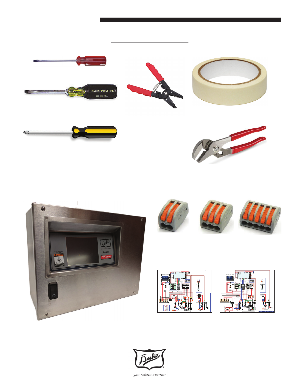
Small Straight Blade Screw Driver
Tools Required
3/16” Straight Blade Screw Driver
Phillips Screw Driver
Wire Strippers
Enclosed In Kit
*155811 Wago-2
Connector
*Quantity
based on kit
Masking Tape
Channel Locks
514803 Wago-3
Connector 3ea.
212106 Wago-5
Connector 1ea.
BRN
DMC K5000
208/240V Retrofit WD
Duke Mfg NPD-StL 11/29/17
ELC0245 Rev A
Front Cover
External
USB
RED
BLU
BRN
BRN
Control Panel
Power Switch
BLU
RED
Cooling
BLU
Fan
BRN
BLK
BLK
RED
RED
BLK
RED
BRN
L2
L3
L1
TERMINAL BLOCK
BRN
RED
BLK
Contactor
RED
RED
ELC0245 Electrical
Diagram for Kits
Part Number based on unit.
116924 and 116925
Also on Page 13
RED
RED
12Vur
-
BLK
P16
GND
P14
+
Beeper
VFD Enable
T-cpl 4
12V
P13
BLU
RX
GRN
-
TX
Beeper
+
T-cpl 3
P1
P2
P12
IO4
-
P15
pcb
+
T-cpl 2
P11
VFD_ft2
VFD_ft3
VFD_ft1
Hi Limit 1
Chem P2
Hi Limit 2
Chem P1
USB
BRN
BRN
BLK
RED
BRN
15A
GND
Stud
ORN
COIL
-
GND
+
0-10V
P17
T-cpl 1
12V
GND
P3
P5
San
Float
GRN
ORN
BLK
YEL
WHT
RED
YEL
BLU
GRN
BRN
PWR PCB
120011
12V
HL 1
HL 2
Chem P2
Chem P1
208 / 230V
BLU
BRN
YEL
BLU
BLU
ORN
GRY
- T4
Connections used for
sanitizer connections
- T3
RED
RED
BLK
BRN
ORN
BRN
COIL
WASH
H1
CONTACTOR
15A
15A
CONTACTOR
CHEM.
PUMP 1
(Optional)
High
Limit
Wash Element:
(2.5K, 5K, 7.5KW)
Sanitizer Connections
P10
SW1 SW2
P4
Chemical Pump Sanitizer
Option
A1
T3
Sw 2
Sw 1
1 2 3 4
1 2 3 4
GRY
BRN
GRY
P1P2
PC
A1 AC
MA MC
S1 SC
H1
HC
Fq. Drive
Variable
S/L2
T/L3
R/L1
U/T1
V/T2
W/T3
Wash T-couple Water
Wash T-couple – Dry Fire
SANITIZER
CHEMICAL
PUMP
BLK
BLK
RED
WHT
RED
BRN
(Optional)
Heated Sanitizer Option
BLK
RED
L1-TB
RED
BRN
L3-TB
BLU
COIL
T4
SANITIZER CONTACTOR
BRN
YEL
GRN
WASH
PUMP 1
WASH
PUMP 2
A1
A1
BLK
H1
T-couples
T-couples
Dry Fire
SANITIZER
Wash Water Temp
FLOAT
SWITCH
High
Limit
Sanitizer Water Temp
*Remove Sheath Strap
Sanitizer Element:
& Bend Sensor Away
2.5kW
DMC K5000
480V Retrofit WD
Duke Mfg NPD-StL 11/29/17 TS
ELC0246 Rev A
BLU
RED
Cooling
Fan
BLK
BLK
RED
BRN
RED
RED
BRN
L2
L3
L1
TERMINAL BLOCK
Transformer
H4
H1
X1 X4
ELC0246 Electrical
Diagram for Kits
116926 and 116927
Also on Page 14
BRN
RED
RED
12Vur
BLK
P16
+
GND
P14
T-cpl 4
Beeper
VFD Enable
12V
P13
BLU
RX
GRN
+
TX
Beeper
T-cpl 3
P1
P2
P12
IO4
Front Cover
USB
External
USB
RED
BLU
BRN
BRN
Control Panel
Power Switch
BRN
BRN
BLU
BRN
GND
Stud
RED
RED
RED
+
P15
pcb
T-cpl 2
P11
VFD_ft2
VFD_ft3
----
VFD_ft1
Hi Limit 1
Chem P2
Hi Limit 2
Chem P1
+
GND
0-10V
P17
T-cpl 1
12V
GND
P3
P5
San
Float
GRN
ORN
BLK
YEL
WHT
RED
YEL
BLU
GRN
PWR PCB
120011
12V
HL 2
HL 1
Chem P2
Chem P1
208 / 230V
BLU
BRN
YEL
BLU
BLU
ORN
GRY
- T4
Connections used for
sanitizer connections
- T3
BLK
RED
RED
RED
BRN
ORN
COIL
CONTACTOR
BLK
BRN
BLU
H1
Contactor
ORN
BRN
COIL
BLK
CHEM.
PUMP 1
(Optional)
High
Limit
Wash Element:
(2.5K, 5K, 7.5KW)
Sanitizer Connections
P10
SW1 SW2
P4
Chemical Pump Sanitizer
Option
T3
A1
Sw 2
Sw 1
1 2 3 4
1 2 3 4
GRY
BRN
GRY
P1P2
PC
A1 AC
MA MC
S1 SC
H1
HC
BRN
Fq. Drive
Variable
S/L2
T/L3
R/L1
U/T1
V/T2
W/T3
SANITIZER
CHEMICAL
PUMP
BLK
BLK
RED
WHT
RED
BRN
(Optional)
Heated Sanitizer Option
BLK
RED
L1-TB
RED
BRN
L3-TB
BLU
Wash T-couple Water
Wash T-couple – Dry Fire
COIL
T4
SANITIZER CONTACTOR
BRN
YEL
WASH
PUMP 1
PUMP 2
A1
A1
GRN
WASH
BLU
BLK
H1
T-couples
T-couples
SANITIZER
FLOAT
Wash Water Temp
SWITCH
High
Limit
Dry Fire
Sanitizer Water Temp
*Remove Sheath Strap
Sanitizer Element:
& Bend Sensor Away
2.5kW
From Heater
4
Retrot Instructions for K5000
CAUTION
K5000 RETROFIT INSTALLATION INSTRUCTIONS
Removal Of Old Control Box
Step 1
Turn O or disconnect power supply.
Before performing any service perform the
Electrical LOCKOUT/TAG OUT Procedure.
Disconnect all circuits. Failure to comply with this procedure can cause property
damage, injury or death.
Reference: LOCKOUT / TAG OUT PROCEDURE
The worker shall check to be sure that no one is operating the machinery BEFORE turning -o
the power. The machine operator shall be informed before the power is turned o. Sudden loss
of power could cause an accident.
All energy sources that could activate the machine shall be locked out (blocked/tagged).
The main valve or main electrical disconnect shall be tested to be sure that the power to the
machine is o.
Electrical circuits shall be checked with proper and calibrated electrical testing equipment. An
electrical failure could energize the equipment even if the switch is in the o position.
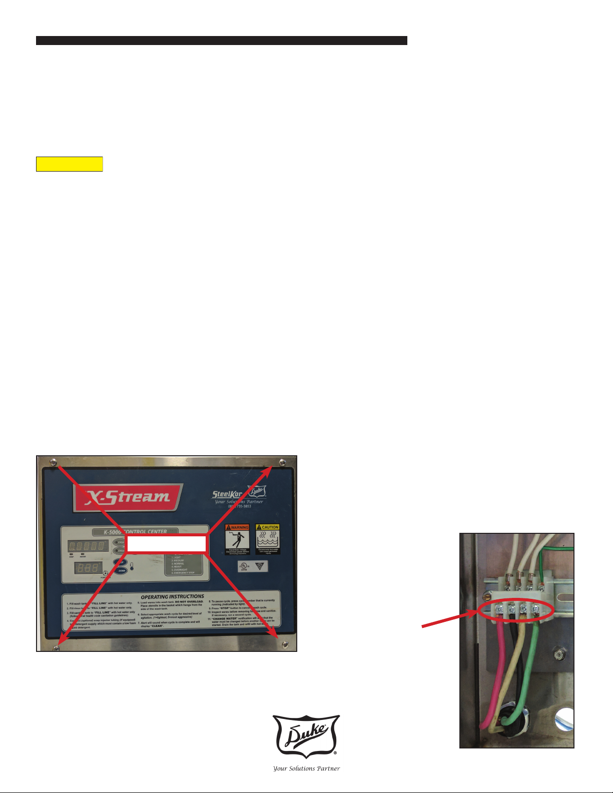
Step 2
Open the control box by removing the four
screws on the front of the control box cover.
REMOVE
Step 3
Using masking tape label all conduits on the
back and all connecting wires.
• Pump 1
• Pump 2
• Chemical Pump
• Element Wash Sink
• Element Sanitizer - If Installed
• Main Power
Step 4
Disconnect the main
power line from the
terminal block.
5
 Loading...