

Owner’s manual
E
1

E
2
Hearty welcome among Ducati fans! Please accept our best
compliments for choosing a Ducati motorcycle. We think you
will ride your Ducati motorcycle for long journeys as well as
short daily trips. Ducati Motor Holding S.p.A. wishes you
smooth and enjoyable riding.
We are continuously working to improve our Technical
Assistance service. For this reason, we recommend that you
strictly follow the instructions in this manual, especially
those regarding the running-in period. This will ensure that
your Ducati motorcycle will continue to be a pleasure to ride.
For repairs or advice, please contact one of our authorised
service centres.
We also provide an information service for all Ducati owners
and enthusiasts for any advice and suggestions you might
need.
Enjoy your ride!
Note
Ducati Motor Holding S.p.A. cannot accept any liability
for errors that may have occurred in the preparation of this
manual. All information in this manual is valid at the time of
going to print. Ducati Motor Holding S.p.A. reserves the right
to make any modifications required due to the ongoing
development of their products.
For your safety, as well as to preserve the warranty, reliability
and worth of your motorcycle, use original Ducati spare parts
only.
Warning
This manual forms an integral part of the motorcycle
and - if the motorcycle is resold - must always be handed
over to the new owner.
E
3

Table of contents
E
General Indications 7
Warranty 7
Symbols 7
Useful information for safe riding 8
Carrying the maximum load allowed 9
Identification data 10
Dashboard 11
Dashboard on handlebar 12
LCD unit functions 14
Vehicle speed indicator 15
Engine rpm indicator (RPM) 16
Clock 17
Coolant temperature 18
Display background colour (Automatic adjustment) 19
Dashboard on tank 19
TFT - Parameter setting/display 21
Total distance covered indicator: “Odometer“ 23
“Trip 1“ meter 24
“Trip 2“ meter 25
4
Distance travelled on fuel reserve: “TRIP FUEL“ 25
Indicator “CONS. AVG“ - Average fuel consumption 26
Indicator “CONS.“ - Instantaneous fuel consumption 26
Indicator “SPEED AVG” - Average speed 27
Indicator “TRIP TIME“ - Trip time 27
Indicator “AIR” - Air temperature 28
Engaged gear indicator 29
“Riding Mode set“ indication 30
Indication if the “LAP” function is active/not active 31
“Riding Style” function (riding style change) 32
Maintenance indicator 34
Maintenance table 34
Residual range indication when the SERVICE is due 36
Indication of range reached for SERVICE 38
Warning indication (Alarms/Signals) 40
“Low” battery level 41
Traction Control (DTC) deactivated 41
Hands Free key (HF) not recognised 42
“Low“ Hands Free key (HF) battery level 42
“High“ engine coolant temperature 43
Steering release error - Steering still locked 43
Dashboard diagnosis 44
“Setting” menu 48
“Riding Mode” customisation 50
DTC (Ducati Traction Control) setting function 52
ENGINE setting function (Engine Power Control) 56
DEFAULT function (Resetting Ducati default parameters) 58
Menu 2 On/Off function 59
Background setting function for the dashboard on tank DASHBOARD 1 62
Backlighting setting function for the dashboard on handlebar
- DASHBOARD 2 64

Digital RPM indication function 66
LAP Activation/Deactivation function (lap time) 68
LAP registration function 70
Stored LAP display function 72
Stored LAP erase function 74
Battery voltage indicator (BATTERY) 76
Clock setting function 78
Units of measurement modification function 80
ABS disabling function 84
The immobilizer system 86
86
Keys
Replacing the battery in the active key 88
Duplicate keys 91
Immobilizer override procedure 92
Light control 96
Controls 101
Position of motorcycle controls 101
“Hands free” system 102
LH switch
Clutch lever
RH switch
Throttle twistgrip
Front brake lever
Rear brake pedal
Gear change pedal
Adjusting the position of the gearchange and rear brake
pedals 117
112
113
114
115
115
116
116
Main components and devices 119
Position on the vehicle 119
Tank filler plug 120
Seat lock 121
Side stand
Passenger grabhandle 125
Adjusting the front fork 126
Adjusting the rear shock absorber 128
124
Directions for use 132
Running-in recommendations 132
Pre-ride checks 134
Engine on/off 136
Moving off 138
Braking 138
Stopping the motorcycle 140
Parking 140
Refuelling
Tool kit and accessories
Main maintenance operations 145
Changing air filter 145
Checking and topping up coolant level 145
Checking brake and clutch fluid level 146
Checking brake pads for wear
Lubricating cables and joints 149
Adjusting throttle control free play 150
Charging the battery 151
Charging and maintenance of the battery during winter
storage 158
Checking drive chain tension
143
144
148
159
E
5

Chain lubrication 160
Replacing the high and low beam bulbs 161
E
Beam setting
Rear-view mirror adjustment
Tubeless tyres 165
Checking engine oil level
Cleaning and replacing the spark plugs
General cleaning 169
Storing the bike away 170
Important notes 170
162
164
167
Scheduled maintenance chart 171
Operations to be carried out by the dealer 171
Operations to be carried out by the dealer 173
Operations to be carried out by the customer 174
Technical data 175
Overall dimensions (mm) 175
Weights 175
Engine 177
Timing system 177
Performance data 178
Spark plugs 178
Fuel system 178
Brakes 179
Transmission 180
Frame 181
Wheels 181
Tyres 181
6
168
Suspensions 181
Exhaust system 182
Colour schemes 182
Electric system 182
Scheduled maintenance reminder 188
For United States of America
version Only 189
Routine maintenance record 199
General Indications
Warranty
In your own interest, and in order to guarantee product
reliability, you are strongly advised to refer to a Ducati Dealer
or Authorised Service Centre for servicing that requires any
particular technical expertise.
Our highly skilled staff have the tools required to perform any
servicing job to the highest professional standards, using
only Ducati original spare parts to ensure full
interchangeability, smooth running and long life.
All Ducati motorcycles come with a Warranty Booklet. The
warranty does not apply to motorcycles used in competitions
or in cases where there is evidence of poor maintenance. If
any motorcycle part is tampered with, modified, or replaced
with parts other than original Ducati spare parts during the
warranty period, the warranty is automatically invalidated.
Symbols
Ducati Motor Holding S.p.A. advises you to read this manual
carefully in order to become familiar with your motorcycle. If
in doubt, please contact a Ducati Dealer or Authorised
Service Centre. The information contained herein will prove
useful on your trips - and Ducati Motor Holding S.p.A. wishes
you smooth, enjoyable riding - and will help you keep the
performance of your motorcycle unchanged for a long time.
This booklet uses a set of symbols with special meanings:
Warning
Failure to comply with these instructions may put you
at risk, and could lead to severe injury or even death.
Important
Risk of damage to the motorcycle and/or its
components.
Note
Additional information about the current operation.
The terms RIGHT and LEFT are referred to the motorcycle
viewed from the riding position.
E
7
Useful information for safe riding
E
Warning
Read this section before riding your motorcycle.
Many accidents are the result of the inexperience of the
rider. Always make sure you have your licence with you; you
need a valid licence that entitles you to ride a motorcycle.
Do not lend your motorcycle to persons who are
inexperienced or do not hold a valid licence.
Both rider and pillion passenger must ALWAYS wear a safety
helmet.
Do not wear loose clothes or accessories that could become
entangled in the controls or limit your field of vision.
Never start or run the engine indoors. Exhaust gases are
toxic and may lead to loss of consciousness or even death
within a short time.
Both rider and pillion passenger should keep their feet on the
footpegs when the motorcycle is in motion.
ALWAYS hold the handlebars firmly with both hands in order
to be ready for sudden changes of direction or in the road
surface. The pillion passenger should ALWAYS hold on to the
special handle onto tail guard with both hands. For details on
rear grab handle refer to “Passenger grabhandle” on page
125.
Ride within the law and observe national and local rules.
ALWAYS respect speed limits where these are posted.
However, ALWAYS adjust your speed to the visibility, road
and traffic conditions you are riding in.
ALWAYS signal your intention to turn or pull to the next lane
in good time using the suitable turn indicators.
8
Be sure you are clearly visible and do not ride within the blind
spot of vehicles ahead.
Be very careful at road junctions, or when riding in areas near
exits from private land or car parks, or on the slip roads to
motorways.
ALWAYS turn off the engine when refuelling.
Be extremely careful not to spill fuel on the engine or on the
exhaust pipe when refuelling.
Do not smoke when refuelling.
While refuelling, it is possible to inhale noxious fuel vapours.
Should any fuel drops be spilled on your skin or clothing,
immediately wash with soap and water and change your
clothing.
ALWAYS remove the key when you leave your motorcycle
unattended.
The engine, exhaust pipes and silencers remain hot for a long
time.
Warning
The exhaust system may still be hot even after engine
is switched off; take special care not to touch the exhaust
system with any part of your body and do not park the
motorcycle next to inflammable material (wood, leaves, etc.).
Park your motorcycle where no one is likely to knock against
it, and use the side stand.
Never park on uneven or soft ground, or your motorcycle
may fall over.
Carrying the maximum load allowed
Your motorcycle is designed for travelling over long
distances with a full load in complete safety.
Even weight distribution is critical to preserving these safety
features and avoiding trouble when performing sudden
manoeuvres or riding on bumpy roads.
Warning
Do not exceed the total permitted weight for the
motorcycle and pay attention to information provided below
regarding load capacity.
Information on load capacity
The total weight of the motorcycle in running order including
rider, passenger, luggage and additional accessories should
not exceed:
400 kg.
Important
Arrange your luggage or heavy accessories in the
lowest possible position and close to motorcycle centre.
Secure the luggage firmly to the motorcycle structure.
Luggage incorrectly secured may cause the motorcycle to
become unstable.
Never attach bulky or heavy objects to the top yoke or front
mudguard, as this would cause dangerous instability.
Do not insert objects into gaps in the frame, where they
could interfere with moving parts.
If the side panniers are fitted (available upon request from
the Ducati spare parts service), divide the baggage and
accessories based on their weight and place them uniformly
inside the side panniers. Lock both side panniers using the
suitable key lock.
Make sure the tyres are inflated to the proper pressure
indicated at page 165 and that they are in good condition.
E
9
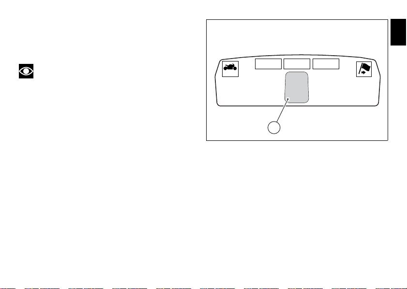
Identification data
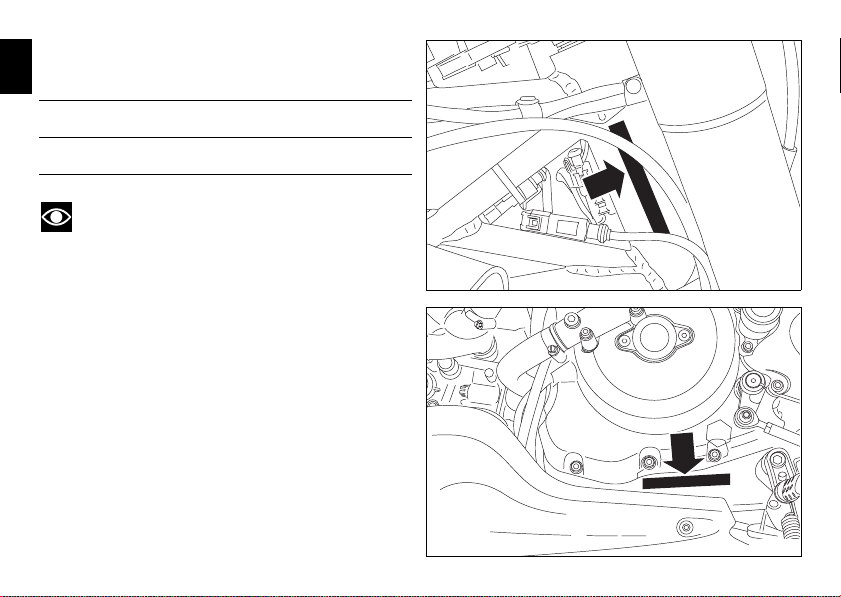
fig. 2
fig. 1
All Ducati motorcycles have two identification numbers, for
E
frame (fig. 1) and engine (fig. 2).
Frame number
Engine number
Note
These numbers indicate the motorcycle model and
should be quoted when ordering spare parts.
10
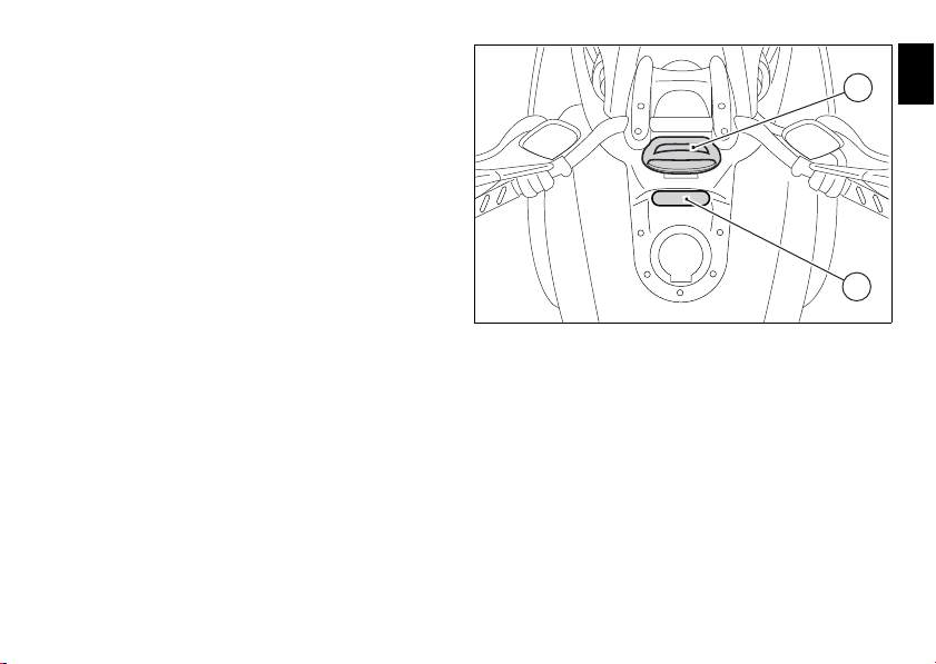
Dashboard
2
1
fig. 3
The vehicle is equipped with two instrument panels: an LCD
(1, fig. 3) located on the handlebar containing the key
indications (speed, rpm, coolant temperature and clock) and
a TFT colour display (2, fig. 3) located in the tank fairing
displaying trip information (riding style set, odometer,
consumption, average speed, etc.) and the setting menu for
activating and setting the various functions.
E
11
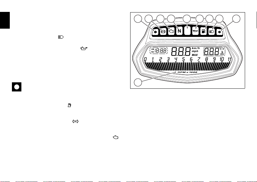
Dashboard on handlebar
fig. 4
1) LCD.
E
2) NEUTRAL LIGHT N (GREEN).
Illuminates when the gearbox is in neutral.
3) HIGH BEAM LIGHT (BLUE).
It turns on to indicate that the high beam lights are on.
4) ENGINE OIL PRESSURE LIGHT (RED).
Illuminates when engine oil pressure is too low. It must turn
on at Key-On, but must turn off a few seconds after the
engine has started.
It may come on briefly if the engine is very hot, but should go
out again as engine speed increases.
Important
If this light (4) stays on, stop the engine or it may suffer
severe damage.
5) FUEL WARNING LIGHT (AMBER YELLOW).
Comes on when fuel is low and there are about 4 litres of fuel
left in the tank.
6) TURN INDICATOR LIGHTS (GREEN).
Illuminates and flashes when the turn indicator is in
operation.
7) “ENGINE/VEHICLE DIAGNOSIS - EOBD” LIGHT
(AMBER YELLOW).
It turns on in the case of “engine” and/or “vehicle” errors
and in some cases will lock the engine.
6 9 7 2 4 5 3 68
1
12
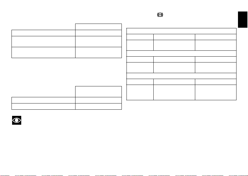
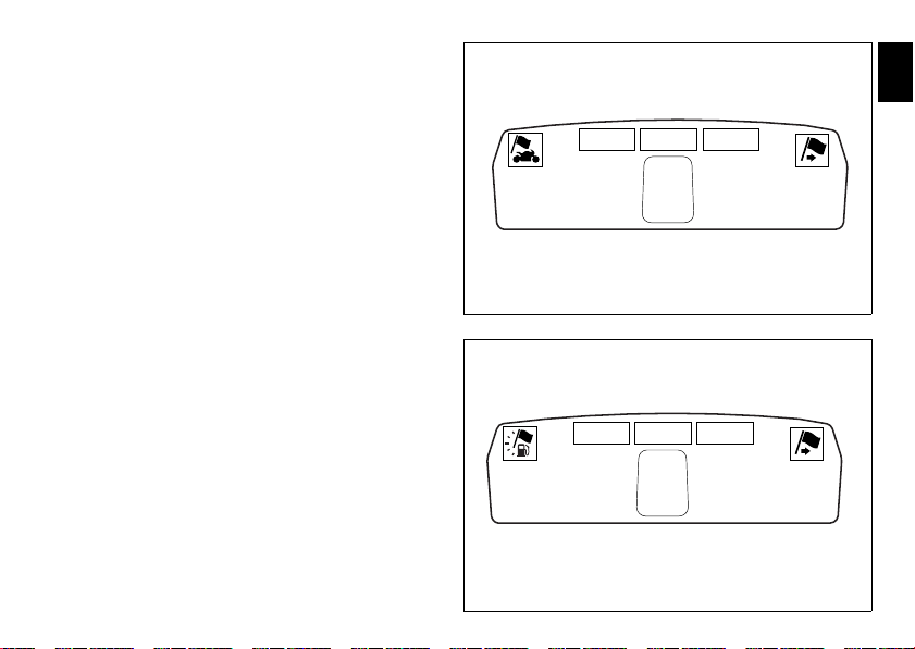
8) Limiter light “Over rev”/ traction control light “DTC”
(RED) (fig. 4):
Over rev light
No limiter Off
1st threshold - no. RPM before
the limiter threshold (*)
Rev limiter (limiter engaged due
to overrevving) (*)
(*) depending on the model, each calibration of the Engine
Control Unit may have a different “setting“ for the
thresholds that precede the rev limiter and the rev limiter
itself.
No intervention Off
DTC intervention On - Flashing
Note
If the Over rev function light and the DTC intervention
light should both come on at the same time, the dashboard
gives priority to the Over rev function.
On - STEADY
On - Flashing
DTC intervention
lights
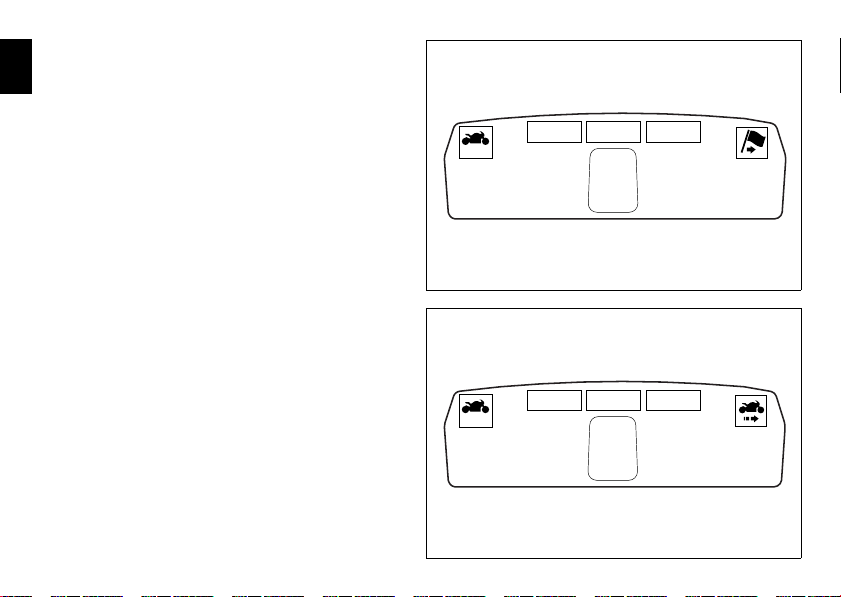
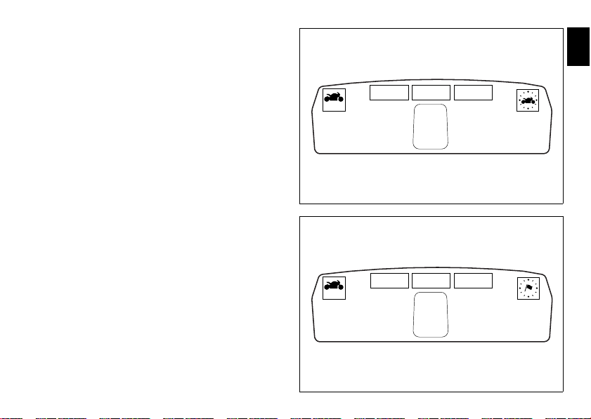
9) ABS LIGHTS (AMBER YELLOW) (fig. 4).
This turns on to indicate that ABS is disabled or not
functioning.
Engine off / speed below 5 Km/h
Light off Light flashing Light steady
ABS disabled with the
menu function “ABS”
Light off Light flashing Light steady
Light off Light flashing Light steady
ABS enabled
and
functioning
Engine on / speed below 5 Km/h
ABS disabled with the
menu function “ABS”
Engine on / speed above 5 Km/h
ABS disabled with the
menu function “ABS”
ABS enabled but not
functioning yet
ABS enabled but not
functioning yet
ABS disabled and not
functioning due to a
problem.
E
13
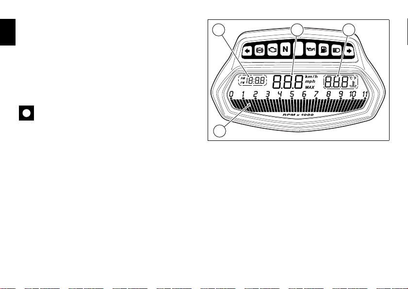
LCD unit functions
fig. 5
E
1) SPEEDOMETER.
Gives road speed
2) REV COUNTER.
Indicates engine revs per minute.
3) CLOCK.
4) WATER TEMPERATURE INDICATOR.
Indicates engine coolant temperature.
Important
Stop riding if the temperature reaches the maximum
value, otherwise the engine might be damaged.
3 41
2
14
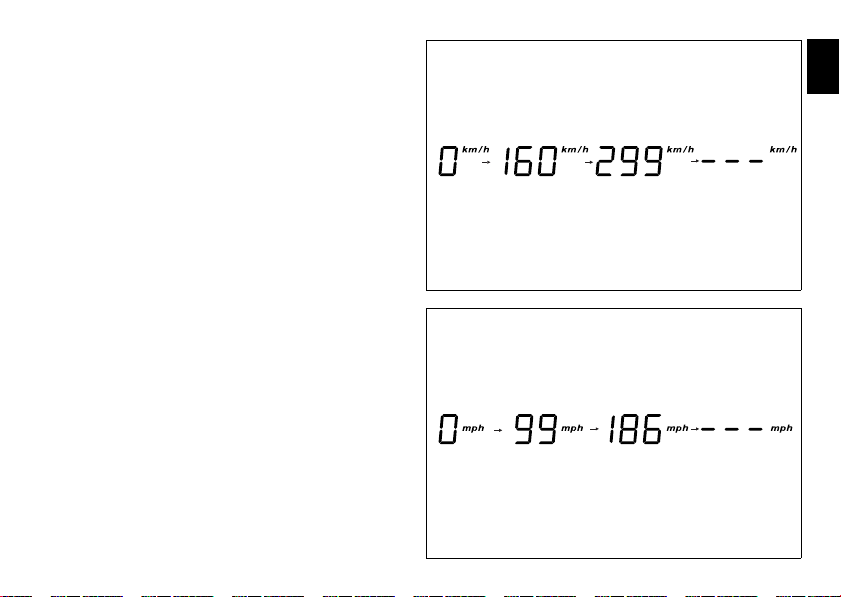
Vehicle speed indicator
fig. 6
fig. 7
This function displays vehicle speed (Km/h or mph
depending on the set measurement system).
The dashboard receives information about the actual speed
and displays the number increased by 5%.
Maximum speed displayed is 299 km/h (186 mph).
Over 299 km/h (186 mph) a series of dashes will be displayed
“- - -” (not flashing).
E
15
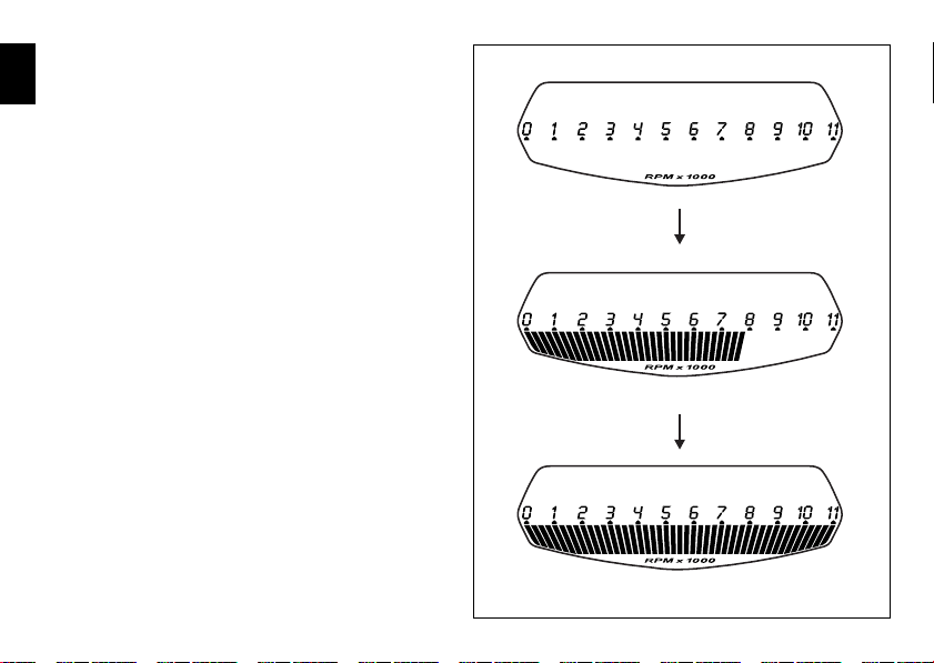
Engine rpm indicator (RPM)
fig. 8
This function displays the rpms.
E
The dashboard receives the engine rpm information and
displays it.
This information is displayed progressively from the left to
the right, identifying the rpms.
16
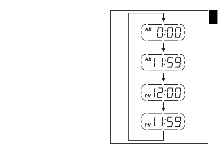
Clock
fig. 9
This function shows the time.
Time is always displayed as follows:
AM from 0:00 to 11:59
PM from 12:00 to 11:59
If battery power is suddenly cut off (Battery OFF), when
battery power is restored and upon next Key-On, the clock is
reset and restarts operating from “0:00“.
E
17
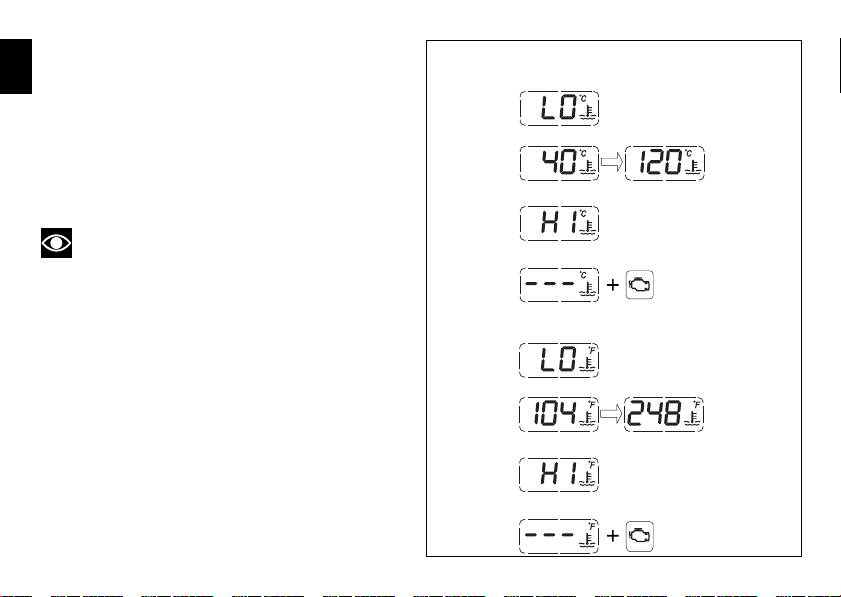
Coolant temperature
Engine
Diagnosis
STEADY READING
STEADY READING
STEADY READING
FLASHING DATUM
FLASHING DATUM
STEADY READING
STEADY READING
STEADY READING
FLASHING DATUM
FLASHING DATUM
Engine
Diagnosis
°C
°F
fig. 10
This function indicates coolant indication state.
E
The temperature unit of measure can be selected (°C or °F).
The reading is indicated as follows:
- if the reading is between - 39°C and +39°C “LO” is
shown flashing on the dashboard (steady);
- if the reading is between +40°C and +120°C it appears
on the dashboard (steady);
- if reading is +121 °C or higher, “HI“ is shown flashing on
the information panel;
Note
In the event of a sensor “error“, a string of flashing
dashes (“- - -“) is shown and the “Engine/vehicle diagnosis EOBD“ light (7, fig. 4) comes on.
18
Display background colour (Automatic
10355 16.3
3
TOT
CONS.AVG
KM/L
TOT
162 HIGH
GEAR
SPORT 03 DTC
4 5
6
7 8
2
1 3
fig. 11
adjustment)
Dashboard background colour is set automatically according
to exterior lighting conditions.
When sensor detects “poor lighting” (night), it switches to
black background mode; vice versa when a “significant”
lighting is detected (day), it switches to white background
mode. It is nevertheless possible to customise this function
through the “setting” menu function “BACK LIGHT DASHBOARD 1”, on page 62, and possibly set one of the
two modes available, NIGHT or DAY, as permanent setting
(or go back to AUTO mode).
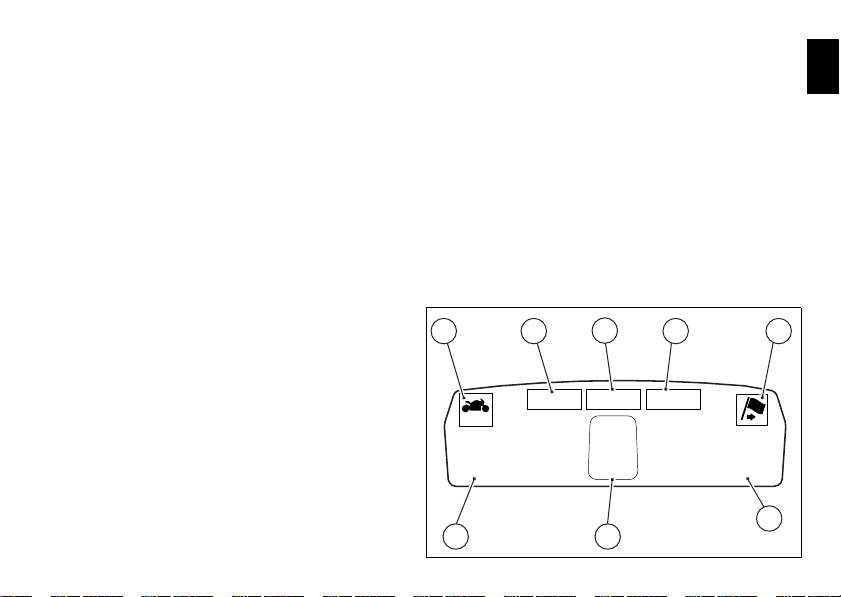
Dashboard on tank
1) Menu 1 (TOT, TRIP1, TRIP2, TRIP FUEL).
2) Menu 2 (CONS.AVG., CONS., SPEED AVG, AIR and
TRIP TIME) if active.
3) Gear / Neutral Indication.
4) Icon referred to the function below from Menu 1.
5) Indication of Engine setting for the currently set riding
6) Currently set Riding Style (Riding Mode)
7) Indication of the intervention level of the DTC (Traction
8) Icon referred to the function below from Menu 2.
style.
Control) for the currently set riding style.
E
19
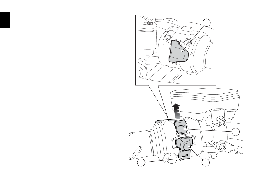
9) CONTROL BUTTON (fig. 12)
10
11
12
9
fig. 12
Button used to display and set dashboard parameters with
E
the position “▲“.
10) CONTROL SWITCH (fig. 12)
Button used to display and set dashboard parameters with
the position “▼“.
11) HIGH-BEAM FLASHER BUTTON FLASH (fig. 12)
The high-beam flash button may also be used to for LAP
functions.
12) RESET BUTTON (fig. 12).
The turn indicators off button may also be used for the
RESET/CONFIRM function on the dashboard and for
activating the “Riding Style“.
20
TFT - Parameter setting/display
10355 16.3
3
TOT
CONS.AVG
KM/L
TOT
162 HIGH
GEAR
SPORT 03 DTC
fig. 13
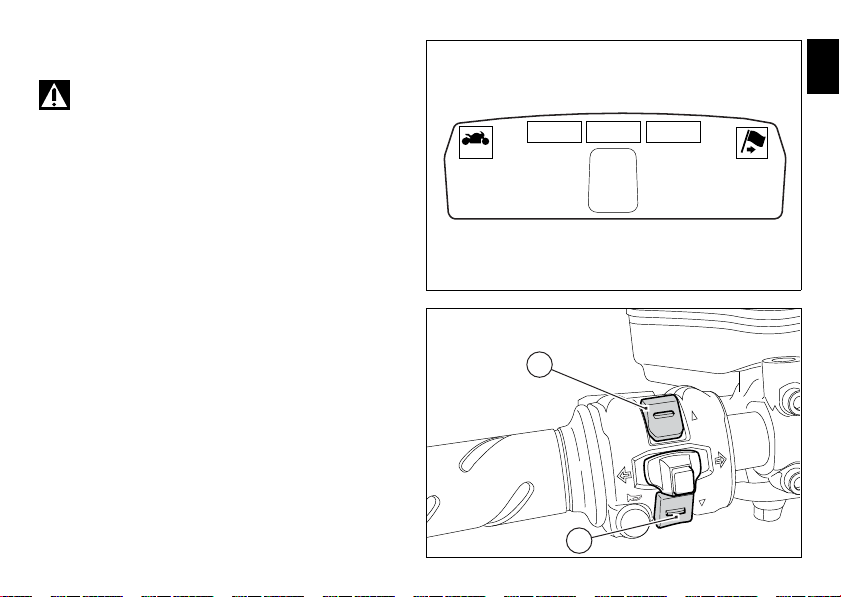
1
2
fig. 14
Warning
Any adjustments to the dashboard must only be
carried out when the motorcycle is stationary. Never operate
the dashboard controls while riding the motorcycle.
At the end of the check, the dashboard always displays as
the “main” indication the Odometer (TOT) on the left and the
Average Fuel Consumption on the right (unless Menu 2 was
disabled).
At the end of the initial check, the dashboard will always
show the “main” display, indicating the following
information:
- Set “Riding Style” (Riding Mode);
- Gear indication (GEAR);
- Menu 1: Odometer (TOT);
- Menu 2: Average Fuel Consumption (CONS. AVG).
By pressing the (1, fig. 14) “▲” button it is possible to switch
to the following functions of menu 1:
- TRIP1 - Trip meter 1;
- TRIP2 - Trip meter 2;
- TRIP FUEL - Distance travelled on fuel reserve (only if
active);
E
21

By pressing the (2, fig. 14) “▼” button it is possible to switch
to the following functions of menu 2:
E
- CONS. - Current fuel consumption;
- SPEED AVG - Average speed;
- TRIP TIME - Trip time;
- AIR - Air temperature;
Note
Menu 2 viewing can be disabled through the “MENU
2” Function of the Setting menu.
22
Total distance covered indicator:
199999 16.3
3
TOT
CONS.AVG
KM/L
TOT
162 HIGH
GEAR
SPORT 03 DTC
10355 16.3
3
TOT
CONS.AVG
KM/L
TOT
162 HIGH
GEAR
SPORT 03 DTC
0 16.3
3
TOT
CONS.AVG
KM/L
TOT
162 HIGH
GEAR
SPORT 03 DTC
fig. 15
“Odometer“
This function shows the total distance covered by the vehicle
(in Km or miles depending on the specific application).
At Key-On the system automatically enters this function.
The odometer reading is stored permanently and cannot be
reset.
If the distance travelled exceeds 199999 km (or 199999
miles), the value “199999” will be displayed permanently.
E
23
“Trip 1“ meter
9999.9 16.3
3
TRIP1
CONS.AVG
KM/L
162 HIGH
GEAR
SPORT
03 DTC
1
fig. 16
This function shows the distance travelled since the Trip
E
meter was last reset (in Km or miles depending on the
specific application).
Holding the button (1, fig. 14) “▲“ pressed for 3 seconds
when this function is displayed resets the trip meter.
When the reading exceeds 9999.9, distance travelled is reset
and the meter automatically starts counting from 0 again.
If the system measurement units are changed at any
moment through the “SET UNITS” function of the Setting
menu, or if there is an interruption in the power supply
(Battery Off), the distance travelled is reset and the count
starts from zero (considering the newly set unit of
measurement).
Note
When this value is reset, also the “Average fuel
consumption”, “Average speed” and “Trip time” functions
are reset.
24
“Trip 2“ meter
9999.9 16.3
3
TRIPFUEL
CONS.AVG
KM/L
162 HIGH
GEAR
SPORT 03 DTC
fig. 18
2
9999.9 16.3
3
TRIP2
CONS.AVG
KM/L
162 HIGH
GEAR
SPORT 03 DTC
fig. 17
This function shows the distance travelled since the Trip
meter was last reset (in Km or miles depending on the
specific application).
Holding the button (1, fig. 14) “▲“ pressed for 3 seconds
when this function is displayed resets the trip meter.
When the reading exceeds 9999.9, distance travelled is reset
and the meter automatically starts counting from 0 again.
If the system measurement units are changed at any
moment through the “SET UNITS” function of the Setting
menu, or if there is an interruption in the power supply
(Battery Off), the distance travelled is reset and the count
starts from zero (considering the newly set unit of
measurement).
Distance travelled on fuel reserve: “TRIP
FUEL“
This function shows the distance travelled on fuel reserve (in
Km or miles depending on the specific application).
When the fuel light comes on, the display automatically
switches to the “TRIP FUEL“ indicator.
Trip fuel reading remains stored even after Key-Off until the
vehicle is refuelled.
Count is interrupted automatically as soon as fuel is topped
up to above minimum level.
When the reading exceeds 9999.9, it is reset and the count
restarts automatically.
E
25
Indicator “CONS. AVG“ - Average fuel
10355 16.3
3
TOT
CONS.AVG
KM/L
TOT
162 HIGH
GEAR
SPORT 03 DTC
fig. 19
10355 16.3
3
TOT
CONS.
KM/L
TOT
162 HIGH
GEAR
SPORT 03 DTC
fig. 20
consumption
E
This function indicates the “average” fuel consumption.
The calculation is made considering the quantity of fuel used
and the km travelled since the last Trip 1 reset. When Trip 1 is
reset, the value is set to zero and the first available value is
shown on the display 10 seconds after the reset. Dashes “- -.-”
are shown on the display during the first 10 seconds when the
value is not yet available.
the datum is expressed in “l / 100” (litres / 100 Km); it is possible
to change the units of measurement for “Consumption” (both
average and instantaneous together) from L/100 to Km/L through
the “SET UNITS” Function of the Setting menu.
The active calculation phase occurs when the engine is running
and the vehicle is stopped (moments when the vehicle is not
moving and the engine is off are not considered).
Indicator “CONS.“ - Instantaneous fuel
consumption
This function indicates the “instantaneous” fuel consumption.
The calculation is made considering the quantity of fuel used
and the distance travelled during the last second. the datum is
expressed in “l / 100” (litres / 100 Km); it is possible to change
the units of measurement for “Consumption” (both average
and instantaneous together) from L/100 to Km/L through the
“SET UNITS” Function of the Setting menu.
The active calculation phase only occurs when the engine is
running and the vehicle is moving (moments when the vehicle
is not moving when speed is equal to 0 and/or when the engine
is off are not considered). Dashes “- -.-”. are shown on the
display when the calculation is not made.
26
Indicator “SPEED AVG” - Average speed
10355 85.4
3
TOT
SPEED AVG
KM/h
TOT
162 HIGH
GEAR
SPORT 03 DTC
fig. 21
10355 11:00
3
TOT
TRIP TIME
h
TOT
162 HIGH
GEAR
SPORT 03 DTC
fig. 22
This function shows the average speed of the motorcycle.
The calculation is made considering the distance and time
travelled since the last Trip 1 reset. When Trip 1 is reset, the
value is set to zero and the first available value is shown on
the display 10 seconds after the reset. Dashes “- -.-” are
shown on the display during the first 10 seconds when the
value is not yet available.
The active calculation phase occurs when the engine is
running and the vehicle is stopped (moments when the
vehicle is not moving and the engine is off are not
considered).
The calculated value is displayed increased by 5% to align it
with the vehicle indicated speed.
It is possible to change the units of measurement of “speed”
(and “distance travelled”) from Km/h (and Km) to mph (and
miles) through the “SET UNITS” function of the Setting menu.
Indicator “TRIP TIME“ - Trip time
This function shows the vehicle trip time.
The calculation is made considering the time travelled since
the last Trip 1 reset. When Trip 1 is reset, the value is set to
zero.
The active phase calculation occurs when the engine is
running and the vehicle is stopped (when the vehicle is not
moving and the engine is off the time is automatically
stopped and restarts when the counting active phase starts
again).
When the reading exceeds 511:00 (511 hours and 00
minutes), the meter is reset and automatically starts
counting from 0 again.
E
27
Indicator “AIR” - Air temperature
10355 25.3
3
TOT
AIR
˚C
TOT
162 HIGH
GEAR
SPORT 03 DTC
fig. 23
fig. 24
This function shows the external temperature.
E
Display limits: -39°C ÷ +124°C
In the event of a sensor FAULT (-40°C,+125°C or
disconnected), a string of dashes “- - -” (not flashing) is
displayed and the “Engine/Vehicle Diagnosis - EOBD” light
(7, fig. 4) comes on.
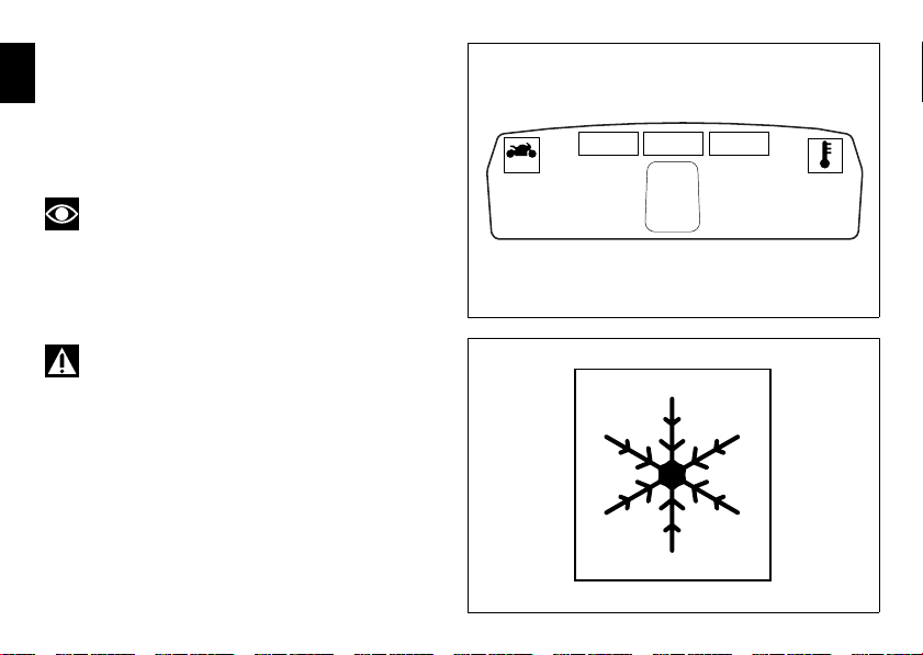
Note
When the vehicle is stopped, the engine heat could
influence the displayed temperature.
When the detected temperature drops to 4°C (39°F), the
display warns that the formation of ice is possible. The
indication turns off when the temperature rises to 6°C (43°F).
Warning
This warning does not exclude the possibility of icy
road sections even at temperatures above 4°C (39°F); when
external temperatures are “low“ it is always recommended
to ride carefully, particularly on sections that are not exposed
to the sun and/or on bridges.
28
Engaged gear indicator
10355 16.3
3
TOT
CONS.AVG
KM/L
TOT
162 HIGH
GEAR
SPORT 03 DTC
1
fig. 25
This function displays the gears (1, fig. 25).
The dashboard receives information and indicates the
engaged gear or “N” for neutral.
Note
In the case of a gear sensor “error”, a dash “-” (not
flashing) will be displayed.
E
29

“Riding Mode set“ indication
10355 16.3
3
TOT
CONS.AVG
KM/L
TOT
162 HIGH
GEAR
SPORT 03 DTC
1
fig. 26
10355 16.3
3
TOT
CONS.AVG
KM/L
162 HIGH
GEAR
SPORT 03 DTC
TOT
2
fig. 27
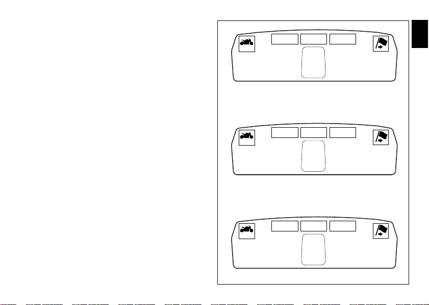
This function indicates the “Riding Style” set for the vehicle.
E
THREE “Riding Modes” are available: SPORT, TOURING and
URBAN.
Each riding mode can be changed using the “RIDING
MODE” function.
Note
The background of the riding mode (SPORT, TOURING
or URBAN) is blue (1, fig. 26) if currently set riding mode
parameters are the default ones (Ducati factory setting) or
yellow (2, fig. 27) if one or more parameters have been
modified (customised) by means of the “RIDING MODE”
function of the Setting menu.
30

Indication if the “LAP” function is active/
10355
LAP
16.3
3
TOT
CONS.AVG
KM/L
162 HIGH
GEAR
SPORT 03 DTC
TOT
fig. 28
not active
This function indicates if “LAP” function (Lap number) is
active.
When “LAP” is not lit up, this means that the function has
been switched off.
The “LAP” function can be activated using the “LAP”
Function of the Setting menu.
E
31

“Riding Style” function (riding style
change)
E
This function changes the motorcycle riding style.
Each riding style is associated with a different intervention
level of the traction control (DTC - Ducati Traction Control)
and different engine power and output.
To change the motorcycle riding mode, press the reset
button once (12, fig. 12) and the “RIDING MODE“ menu will
appear on the display.
The desired riding style can be selected by pressing the
same reset button multiple times (12, fig. 12). Press the
same button for 3 seconds to confirm the riding style.
If the twistgrip is closed (vehicle stopped) the riding style
change will occur immediately; if the twistgrip grip is open
(vehicle moving) the message “CLOSE THROTTLE TO
ACTIVATE” will appear on the display, which means that the
throttle must be closed; this message will appear for 5
seconds, during which the gas must be closed in order to
activate the new riding style.
If the twistgrip is not closed after 5 seconds, the procedure
is aborted (no change is made).
If the “RIDING MODE” menu is activated and the reset
button is not pressed (12, fig. 12) for 10 consecutive
seconds, the dashboard will automatically exit the display
mode without making any change.
32
Warning
Ducati recommends changing the riding style when
the vehicle is stopped. If the riding style is changed while
riding, be very careful (it is recommended to change the
riding style at a low speed).

SPORT TOURING
RIDING MODE
URBAN
SPORT TOURING
RIDING MODE
URBAN
CLOSE THROTTLE TO ACTIVATE
RIDING MODE
CLOSE THROTTLE TO ACTIVATE
RIDING MODE
CLOSE THROTTLE TO ACTIVATE
RIDING MODE
SPORT TOURING
RIDING MODE
URBAN
10355 16.3
3
TOT
CONS.AVG
KM/L
162 HIGH
GEAR
SPORT 03 DTC
TOT
10355 16.3
3
TOT
CONS.AVG
KM/L
162 HIGH
GEAR
TOURING 03 DTC
TOT
10355 16.3
3
TOT
CONS.AVG
KM/L
162 HIGH
GEAR
URBAN 03 DTC
TOT
Press RESET for
3 sec.
fig. 29
Press RESET
Press RESET for
3 sec.
Press RESET for
3 sec.
Press RESET
Press RESET
Press RESET
E
33

Maintenance indicator
This function indicates that the vehicle is about to or has
E
travelled a distance for which an Authorised Ducati Service
Centre should be contacted to have the general maintenance
or oil change performed.
Maintenance table
Indicator Mileage travelled count down -1000
11000
2
3
4
5
6
7
8
9
11000
12000
23000
24000
35000
36000
47000
48000
59000
60000
71000
72000
83000
84000
95000
96000
34
DESMO SERVICE
count down -1000
OIL SERVICE
DESMO
SERVICE
OIL SERVICE

First warning - OIL SERVICE 1000 Km
10355
3
TOT
162 HIGH
GEAR
SPORT
03 DTC
TOT
OIL
SERVICE
1
fig. 30
10355
3
TOT
162 HIGH
GEAR
SPORT 03 DTC
TOT
16.3
CONS.AVG
KM/L
OIL
SERVICE
2
fig. 31
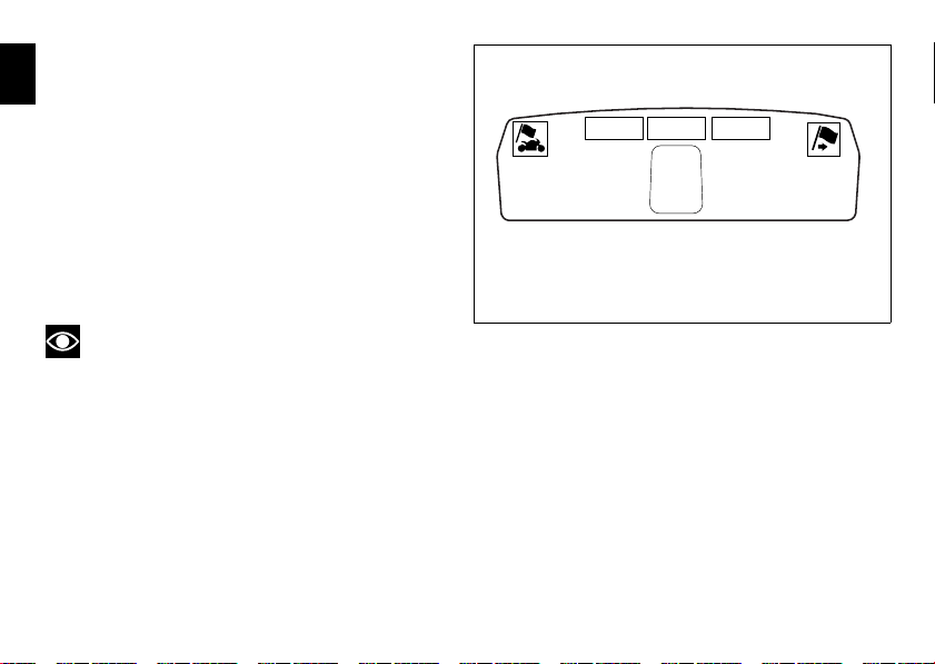
The first warning is activated at 1000 Km (600 miles) of
odometer reading.
The (red) warning is activated as a large icon for 10 seconds
upon every Key-On (1, fig. 30) then as a small warning that
remains displayed (2, fig. 31) until it is reset.
Warning
This message can only be reset by the Ducati Dealer or
Authorised Service Centre that performs the maintenance.
E
35

Residual range indication when the
SERVICE is due
E
After resetting the first OIL SERVICE warning (triggered at
1000 Km), upon every Key-On the system displays the
indication of which type of service should be performed next
(OIL SERVICE or DESMO SERVICE) and the residual range.
A (green) warning (1, fig. 32) is activated for 2 seconds on
every Key-On; while 1000 Km before the threshold an (amber
yellow) warning (2, fig. 32) is activated for 5 seconds upon
every Key-On.
Warning
This message can only be reset by the Ducati Dealer or
Authorised Service Centre that performs the maintenance.
36

10355
3
TOT
162 HIGH
GEAR
SPORT
03 DTC
TOT
- 10500
Km
10355
3
TOT
162 HIGH
GEAR
SPORT
03 DTC
TOT
- 1000
Km
10355
3
TOT
162 HIGH
GEAR
SPORT
03 DTC
TOT
- 10500
Km
10355
3
TOT
162 HIGH
GEAR
SPORT
03 DTC
TOT
- 1000
Km
21
1 2
fig. 32
OIL SERVICE (Count-down)
DESMO SERVICE (Count-down)
E
37

Indication of range reached for SERVICE
When service coupon threshold is achieved, upon every Key-
E
On the system displays the indication of the type of
intervention that is required (OIL SERVICE or DESMO
SERVICE).
The (red) warning is activated as a large icon for 10 seconds
upon every Key-On (1, fig. 33) then as a small warning that
remains displayed (2, fig. 33) until it is reset.
After reset, the system will display again the type of
intervention required next and the residual range (as
described in the previous paragraph).
Warning
This message can only be reset by the Ducati Dealer or
Authorised Service Centre that performs the maintenance.
38

10355
3
TOT
162 HIGH
GEAR
SPORT 03 DTC
TOT
16.3
CONS.AVG
KM/L
OIL
SERVICE
10355
3
TOT
162 HIGH
GEAR
SPORT
03 DTC
TOT
OIL
SERVICE
10355
3
TOT
162 HIGH
GEAR
SPORT
03 DTC
TOT
DESMO
SERVICE
10355
3
TOT
162 HIGH
GEAR
SPORT 03 DTC
TOT
16.3
CONS.AVG
KM/L
DESMO
SERVICE
1
1 2
2
fig. 33
DESMO SERVICE
OIL SERVICE
E
39

Warning indication (Alarms/Signals)
10355
3
TOT
162 HIGH
GEAR
SPORT
LOW
BATTERY
03 DTC
TOT
10355
3
TOT
162 HIGH
GEAR
SPORT
03 DTC
TOT
LOW
BATTERY
16.3
CONS.AVG
KM/L
1
2
fig. 34
The dashboard activates in real-time some warnings /
E
malfunction that are not dangerous for the correct operation
of the vehicle.
At Key-On (at the end of the check) one or more “warnings”
are displayed if they are active.
When a “warning” is triggered, the indication (amber yellow)
remains well visible for 10 seconds (1, fig. 34) then becomes
smaller (2, fig. 34).
If there are multiple indicators, they will scroll automatically
every 3 seconds.
activated.
The following “warnings” could be displayed:
- “Low” battery level (LOW BATTERY);
- Traction Control “deactivated” (DTC OFF);
- Hands Free key (HF) “not recognised”;
- “Low” Hands Free key (HF) battery level;
- “High” Engine coolant temperature (HIGH TEMP);
- Steering release error - Steering still locked (Unlock error).
When one or more “warnings” are active, it is possible to go
to other functions by pushing button (2, fig. 14) “▼”.
Note
No signal lights turn on if one or more “warnings” are
40

“Low” battery level
LOW
BATTERY
fig. 35
DTC
OFF
fig. 36
The activation of this (amber yellow) “warning” indicates
that the status of the battery vehicle is low.
It is activated when the battery voltage is 11.0 Volt.
Note
In this case, Ducati recommends charging the battery
as soon as possible with the specific device, as it is possible
that the vehicle will not start.
Traction Control (DTC) deactivated
The activation of this (amber yellow) “warning” indicates
that DTC (Ducati Traction Control) has been turned off.
Note
In this case, Ducati recommends being very careful
when riding as the vehicle behaviour will be different in
comparison to when operating with the Traction Control
activated.
E
41

Hands Free key (HF) not recognised
fig. 37
fig. 38
The activation of this (amber yellow) “warning” indicates
E
that the Hands Free system does not detect the active key
(1, fig. 62) near the vehicle.
Note
In this case, Ducati recommends checking that the
active key (1, fig. 62) is near the vehicle (and has not been
lost) and that it functions properly.
“Low“ Hands Free key (HF) battery level
The activation of this (amber yellow) “warning” indicates
that the Hands Free system has detected that the battery
that permits the active key (1, fig. 62) to communicate and
turn the vehicle on is almost discharged.
Note
In this case, Ducati recommends replacing the battery
as soon as possible as described in the paragraph “Replacing
the active key battery” (page 88).
42

“High“ engine coolant temperature
HIGH TEMP
fig. 39
UNLOCK
ERROR
fig. 40
The activation of this (amber yellow) “warning” indicates
that the engine coolant temperature is high.
It is activated when the temperature reaches 121°C (250°F).
Note
In this case, Ducati recommends stopping and shutting
off the engine immediately; make sure that the fans are
working.
Steering release error - Steering still
locked
The activation of this (amber yellow) “warning” indicates
that the Hands Free System was not able to extract the
steering lock.
Warning
In this case, Ducati recommends turning the vehicle
off and on (Key-Off / Key-On) holding the handlebar pressed
down to the end stop. If the signal remains (and the steering
does not “release”) contact a Ducati Dealer or Authorised
Service Centre.
E
43

Dashboard diagnosis
10355 16.3
3
TOT
CONS.AVG
KM/L
TOT
162 HIGH
GEAR
SPORT 03 DTC
10355
FREE
HANDS
GENERIC
!
FREE
HANDS
GENERIC
!
3
TOT
TOT
162 HIGH
GEAR
SPORT
03 DTC
1
2
fig. 41
This function identifies any abnormal vehicle behaviours.
E
The dashboard activates any abnormal vehicle behaviours in
real time (ERRORS).
At Key-On (at the end of the check) one or more “ERRORS”
are displayed in red (only if they are active).
When an “error” is triggered, the indication (red) remains
well visible for 10 seconds (1, fig. 41) then becomes smaller
(2, fig. 41).
If there are multiple errors, they will scroll automatically
every 3 seconds. The “Engine/vehicle diagnosis - EOBD”
light on dashboard located on handlebar (7, fig. 4) always
turns on when one or more errors are activated.
The table below shows the errors that can be displayed.
a Ducati Dealer or Authorised Service Centre.
Warning
When one or more errors are displayed, always contact
44

WARNING LIGHT ERROR MESSAGE ERROR
BBS/DTC Black Box / Traction Control control unit
GEAR SENSOR Gear sensor
FUEL SENSOR Fuel Level Sensor
SPEED SENSOR Speed sensor
EXVL SYSTEM Exhaust valve starter motor
UNKNOW DEVICE Unknown control unit
DEVICE ECU ECU control unit not functioning
DEVICE DSB SLAVE Dashboard on handlebar not functioning
DEVICE HANDS FREE Hands Free control unit not functioning
DEVICE BBS DTC Black Box / Traction Control control unit not functioning
THROTTLE POSITION Incorrect throttle position
E
45

WARNING LIGHT ERROR MESSAGE ERROR
E
ACCELER. POSITION Incorrect accelerator position
ETV Motor relay or Throttle Motor not functioning
DEVICE DBS MASTER Dashboard on tank not functioning
PRESSURE SENSOR Atmospheric pressure sensor
ENGINE TEMP. Engine Temperature Sensor
T-AIR SENSOR Air Temperature Sensor
FUEL INJECT. Injection relay
COIL Coil
INJECTOR Injector
PICK UP Timing/rpm sensor
LAMBDA Lambda sensor
FAN RELAY Fan relay
46

WARNING LIGHT ERROR MESSAGE ERROR
CAN LINE CAN communication line
BATTERY Battery voltage (HIGH or LOW)
DEVICE ABS ABS control unit not functioning
STOP LIGHT Rear stop light
ECU GENERIC ECU error
KEY HF communication problem
HANDS FREE GENERIC Hands Free ECU error
E
47

“Setting” menu
This menu is used to enable/disable and set some
E
motorcycle functions.
To access the “setting menu” press the button (2, fig. 14)
“▼” for 3 seconds.
Note
When within this menu no other function can be
displayed.
Important
For safety reasons, the setting menu can only be
accessed when motorcycle speed is lower than or equal to
20 Km/h. If this menu is open and the speed of the
motorcycle exceeds 20 km/h, the dashboard automatically
exits the menu and returns to the “main“ display.
48
The setting menu contains the following “items”:
- RIDING MODE
- MENU 2
- BACK LIGHT
-RPM
-PIN CODE
-LAP
- BATTERY
-CLOCK
- SET UNITS
-ABS
- EXIT
To quit the setting menu, use button (1, fig. 14) “▲” or
button (2, fig. 14) “▼” to select the “EXIT” indication and
press the reset button (12, fig. 12).

RIDING MODE RPM
MENU
BATTERY ABS
MENU 2 PIN CODE CLOCK
BACK LIGHT LAP SET UNITS EXIT
RIDING MODE RPM
MENU
BATTERY ABS
MENU 2 PIN CODE CLOCK
BACK LIGHT LAP SET UNITS EXIT
RIDING MODE RPM
MENU
BATTERY ABS
MENU 2 PIN CODE CLOCK
BACK LIGHT LAP SET UNITS EXIT
RIDING MODE RPM
MENU
BATTERY ABS
MENU 2 PIN CODE CLOCK
BACK LIGHT LAP SET UNITS EXIT
RIDING MODE RPM
MENU
BATTERY ABS
MENU 2 PIN CODE CLOCK
BACK LIGHT LAP SET UNITS EXIT
RIDING MODE RPM
MENU
BATTERY ABS
MENU 2 PIN CODE CLOCK
BACK LIGHT LAP SET UNITS EXIT
RIDING MODE RPM
MENU
BATTERY ABS
MENU 2 PIN CODE CLOCK
BACK LIGHT LAP SET UNITS EXIT
RIDING MODE RPM
MENU
BATTERY ABS
MENU 2 PIN CODE CLOCK
BACK LIGHT LAP SET UNITS EXIT
RIDING MODE RPM
MENU
BATTERY ABS
MENU 2 PIN CODE CLOCK
BACK LIGHT LAP SET UNITS EXIT
RIDING MODE RPM
MENU
BATTERY ABS
MENU 2 PIN CODE CLOCK
BACK LIGHT LAP SET UNITS EXIT
RIDING MODE RPM
MENU
BATTERY ABS
MENU 2 PIN CODE CLOCK
BACK LIGHT LAP SET UNITS EXIT
fig. 42
“▼”
Press “▼” for 3 sec.
“▼”
“▼”
“▼”
“▼”
“▼”
“▼”
“▼”
“▼”
“▲”
“▲”
“▲”
“▲”
“▲”
“▲”
“▲”
“▲”
“▲”
“▲”
“▼”
E
49

“Riding Mode” customisation
10355 16.3
3
TOT
CONS.AVG
KM/L
TOT
162 HIGH
GEAR
SPORT 03 DTC
1
fig. 43
This function customises each riding style.
E
To access the function it is necessary to view the “setting”
menu page 48, using button (1, fig. 14) “▲” or (2, fig. 14)
“▼” select the “RIDING MODE” function and press the
reset button (12, fig. 12) to go to next page.
When accessing the function, the three riding modes appear
on the display; to customise the parameters, use button (1,
fig. 14) “▲” or (2, fig. 14) “▼” to select the riding mode to
be changed and press the reset button (12, fig. 12) to
confirm.
The parameters that can be “customised” are “DTC” (Ducati
Traction Control) and '”ENGINE”.
Any parameter change made is saved in the memory also
after a Battery-Off.
To change the DTC parameters see the “DTC (Ducati
Traction Control)“ paragraph page 52.
To change the Engine parameters see the “ENGINE (engine
power control)” paragraph page 56.
The parameters set by Ducati for each individual riding style
can be restored with the ”DEFAULT” function.
To reset the “default” parameters see the “DEFAULT
(Resetting Ducati default parameters)” paragraph page 58.
Note
If the parameters have not been modified (customised)
or are reset using the “DEFAULT” function, when you quit
the Setting menu, in the “main“ screen, the “background”
indicating the riding style (SPORT, TOURING or URBAN)
becomes blue (1, fig. 43).
Warning
Changes should only be made to the parameters by
people who are experts in motorcycle setup; if the
parameters are changed accidentally, use the “DEFAULT”
function to reset the parameters.
50

E
SPORT TOURING
RIDING MODE
URBAN
EXIT
RIDING MODE RPM
MENU
BATTERY ABS
MENU 2 PIN CODE CLOCK DDA
BACK LIGHT LAP SET UNITS EXIT
DTC DEFAULT
SPORT
ENGINE
EXIT
DTC DEFAULT
TOURING
ENGINE
EXIT
DTC DEFAULT
URBAN
ENGINE
EXIT
SPORT TOURING
RIDING MODE
URBAN
EXIT
SPORT TOURING
RIDING MODE
URBAN
EXIT
SPORT TOURING
RIDING MODE
URBAN
EXIT
Press RESET
Press “▼”
Press “▼”
Press “▲”
Press RESET
Press RESET
Press RESET
fig. 44
Press “▼”
Press “▲”
Press “▼”
Press “▲”
51

DTC (Ducati Traction Control) setting
function
E
This function allows you to customise the level of DTC
intervention (Ducati Traction Control) or disable it for every
riding mode.
To access the function it is necessary to view the “setting”
menu page 48, using button (1, fig. 14) “▲” or (2, fig. 14)
“▼” select the “RIDING MODE” function and press the
reset button (12, fig. 12) to go to next page. Use button (1,
fig. 14) “▲” or (2, fig. 14) “▲” to select the riding style to
change and press the reset button (12, fig. 12).
To go to next page use button (1, fig. 14) “▲” or (2, fig. 14)
“▲” to select the “DTC“ indication and press the reset
button again (12, fig. 12) to confirm selection.
When accessing the function, the currently set DTC level
appears at the left-hand side of the display, inside a rectangle
(ex.: DTC 1). Use button (1, fig. 14) “▲” or (2, fig. 14) “▲” to
select the new intervention level (1 to 8) or OFF to disable
the Traction Control; after selecting the new setting, press
the reset button (12, fig. 12) to highlight “MEMORY”
indication. At this point, store the new setting by pressing
and holding the reset button (12, fig. 12) for 3 seconds with
“MEMORY” displayed. If the setting has been stored
successfully, the display will show “MEMORIZED” in green
for 2 seconds and the EXIT option will be highlighted
automatically.
To exit the setting function, press the reset button (12, fig.
12) where “EXIT” is highlighted.
The DTC intervention increases, passing from level 1 to level
8.
52
The following table indicates the most suitable level of DTC
intervention for the various riding types as well as the default
settings in the “RIDING MODE“ that can be selected by the
rider:
DTC
Riding
level
type
1 SPORT Sporty riding on a road for
2 SPORT-
TOURING
3 TOURING Normal riding on a road It is the default
4 TOURING 2 Normal riding on a road for
5 URBAN Riding in town It is the default
6 URBAN 2 Riding in town for less
7 WET Riding with damp ground /
8 RAIN Riding with wet ground /
Use Default?
expert users and on track
Riding on a road for expert
users
less expert users
expert users
It is the default
setting of the
SPORT RIDING
MODE
/
setting of the
TOURING RIDING
MODE
/
setting of the
URBAN RIDING
MODE
/

MEMORYDTC OFF
OFF
SPORT
ENGINE
1526374
8
EXIT
MEMORYDTC OFF
OFF
SPORT
ENGINE
1526374
8
EXIT
DTC DEFAULT
SPORT
ENGINE
EXIT
MEMORIZEDDTC OFF
OFF
SPORT
ENGINE
1526374
8
EXIT
MEMORIZEDDTC OFF
OFF
SPORT
ENGINE
1526374
8
EXIT
MEMORYDTC OFF
OFF
SPORT
ENGINE
1526374
8
EXIT
SPORT TOURING
RIDING MODE
URBAN
EXIT
fig. 45
Press RESET
Press “▼”
Press RESET
Press “▲”
Press RESET for
3 sec.
Press RESET
Press RESET
E
53

Tips on how to select the sensitivity level
E
Warning
The 8 level settings of the DTC were calibrated using
tyres of the same make, model and size as those originally
fitted to the motorcycle.
The use of tyres of different size to the original tyres may
alter the operating characteristics of the system.
In the case of minor differences, such as for example, tyres
of a different make and/or model than the original, but with
the same dimensions (rear = 240/45-17; front = 120/70-17),
it may be sufficient to simply select the most suitable level
setting from those available to restore optimal system
operation.
If tyres of a different size class are used or if the tyre
dimensions differ significantly from the original tyres, it may
be that the system operation is affected to the point where
none of the 8 available level settings will give satisfactory
results.
In this case is it is advisable to deactivate the traction control
system.
If level 8 is selected, the DTC control unit will kick in at the
slightest hint that the rear wheel is starting to spin.
Between level 8 and level 1 there are a further 6 intermediate
levels. The level of DTC intervention decreases in equal
steps from level 8 to level 1.
Level 1 allows considerable spinning and requires constant
and good grip to operate correctly; Level 1 is thus
recommended for expert users only and with excellent road
conditions.
54
The choice of the correct level depends on 3 main variables:
1) The grip (type of tyre, amount of tyre wear, the road/
track surface, weather conditions, etc.)
2) The characteristics of the path/circuit (bends all taken at
similar speeds or at very different speeds)
3) The riding style (whether the rider has a “smooth” or a
“rough” style)
The relation of the DTC intervention level to grip conditions:
The choice of level setting depends greatly on the grip
conditions of the track/circuit (see below, tips for use on the
track and on the road).
The relation of the DTC intervention level to the circuit
characteristics:
If all the corners on the track/circuit can be taken at a similar
speed, it will be easier to find an intervention level that is
satisfactory for every bend; on the other hand, if the track
has, for example, one corner that is much slower than all the
others, it will necessary to find a compromise level (on the
slow corner the DTC will tend to control more than on the
faster corners).
The relation of the DTC intervention level to riding style:
The DTC will tend to kick in more with a “smooth” riding
style, where the bike is leaned over further, rather than with
a “rough” style, where the bike is straightened up as quickly
as possible when exiting a turn.

Tips for use on the track
We recommend level 8 be used for a couple of full laps (to
allow the tyres to warm up) in order to get used to the
system. Then try levels 7, 6, etc., in succession until you
identify the DTC intervention level that suits you best (always
try each level for at least two laps to allow the tyres to warm
up).
Once you have found a satisfactory setting for all the corners
except one or two slow ones, where the system tends to
kick in and control too much, you can try to modify your riding
style slightly to a more “rough” approach to cornering i.e.
straighten up more rapidly on exiting the corner, instead of
immediately trying a different level setting.
Tips for use on the road
Activate the DTC, select level 8 and ride the motorcycle in
your usual style; if the level of DTC intervention seems
excessive, try reducing the setting to levels 7, 6, etc., until
you find the level that suits you best.
If changes in the grip conditions and/or circuit characteristics
and/or your riding style, and the level setting is no longer
suitable, switch to the next level up or down and proceed as
described above to determine the best setting (e.g. if with
level 7 the DTC intervention seems excessive, switch to
level 6; alternatively, if on level 7 you cannot perceive any
DTC intervention, switch to level 8).
E
55

ENGINE setting function (Engine Power
Control)
E
This function customises engine power and output.
To access the function it is necessary to view the “setting”
menu page 48, using button (1, fig. 14) “▲” or (2, fig. 14)
“▼” select the “RIDING MODE” function and press the
reset button (12, fig. 12) to go to next page.
Use button (1, fig. 14) “▲” or (2, fig. 14) “▼” to select the
riding mode to be changed and press the reset button (12,
fig. 12) to access the next page. Now use button (1, fig. 14)
“▲” and (2, fig. 14) “▼” to select the “ENGINE“ indication
and press the reset button again (12, fig. 12) to confirm
selection.
When accessing the function, the engine setting (ENGINE
162 HIGH, 162 LOW o 100 HP) appears at the right-hand side
of the display, inside a rectangle.
Note
In Japan and France versions, the display displays the
settings (ENGINE HIGH, MIDDLE or LOW).
Using button (1, fig. 14) “▲” or (2, fig. 14) “▼” select one of
the three available engine settings; after selecting the new
setting, press the reset button (12, fig. 12) to highlight
“MEMORY” indication.
At this point, store the new setting by pressing and holding
the reset button (12, fig. 12) for 3 seconds with “MEMORY”
displayed. If the setting has been stored successfully, the
display will show “MEMORIZED” in green for 2 seconds and
the EXIT option will be highlighted automatically.
56
To exit the setting function, press the reset button (12, fig.
12) where “EXIT” is highlighted.

E
DTC DEFAULT
SPORT
ENGINE
EXIT
DTC MEMORY
SPORT
ENGINE
162 HIGH
EXIT
SPORT TOURING
RIDING MODE
URBAN
EXIT
162 HIGH
162 LOW
100 HP
DTC MEMORY
SPORT
ENGINE
162 HIGH
EXIT
162 HIGH
162 LOW
100 HP
DTC MEMORY
SPORT
ENGINE
162 HIGH
EXIT
162 HIGH
162 LOW
100 HP
DTC MEMORIZED
SPORT
ENGINE
162 LOW
EXIT
162 HIGH
162 LOW
100 HP
DTC MEMORIZED
SPORT
ENGINE
162 LOW
EXIT
162 HIGH
162 LOW
100 HP
DTC MEMORY
SPORT
ENGINE
HIGH
EXIT
HIGH
MIDDLE
LOW
DTC MEMORY
SPORT
ENGINE
HIGH
EXIT
HIGH
MIDDLE
LOW
DTC MEMORY
SPORT
ENGINE
HIGH
EXIT
HIGH
MIDDLE
LOW
HIGH
LOW
DTC MEMORIZED
SPORT
EXIT
DTC MEMORIZED
SPORT
ENGINE
MIDDLE
EXIT
HIGH
MIDDLE
LOW
ENGINE
MIDDLE
MIDDLE
fig. 46
Press RESET
Press
RESET
Press RESET
“▲”
Press RESET
Press RESET
“▼”
“▲”“▼”
Press
RESET
Press RESET for 3 sec.
Press RESET
Press RESET for 3 sec.
Vs. Fra, Jap
57

DEFAULT function (Resetting Ducati
DTC DEFAULT
SPORT
ENGINE
EXIT
PLEASE WAIT...
DEFAULT OK
DTC DEFAULT
SPORT
ENGINE
EXIT
SPORT TOURING
RIDING MODE
URBAN
EXIT
fig. 47
Press RESET
Press RESET
Press RESET for 3 sec.
default parameters)
E
This function resets the parameters set by Ducati for each
riding style.
To access the function it is necessary to view the “setting”
menu page 48, using button (1, fig. 14) “▲” or (2, fig. 14)
“▼” select the “RIDING MODE” function and press the
reset button (12, fig. 12) to go to next page.
Use button (1, fig. 14) “▲” or (2, fig. 14) “▼” to select the
riding mode to be reset to default (initial) parameters and
press the button (12, fig. 12) to access the next page. Now,
using button (1, fig. 14) “▲” or (2, fig. 14) “▼” select
“DEFAULT” indication.
To restore original default parameters, press and hold the
reset button (12, fig. 12) for 3 seconds.
For the parameter reset, approx. 3 seconds are needed
during which “PLEASE WAIT…” will appear on the display;
at the end of the procedure, “DEFAULT OK“ will appear on
the display to indicate that the parameters were reset.
Important
This procedure restores the parameters for all riding
styles.
To exit the setting function, press the reset button (12, fig.
12) where “EXIT” is highlighted.
58

Menu 2 On/Off function
3
TOT
KM
50355
162 HIGH
GEAR
SPORT
03 DTC
TOT
10355
LAP
16.3
3
TOT
CONS.AVG
KM/L
162 HIGH
GEAR
SPORT 03 DTC
TOT
fig. 48
Menu 2 “ON”
Menu 2 “OFF”
This function turns off and back on the Menu 2.
If Menu 2 is disabled, the functions for average fuel
consumption (CONS.AVG), instantaneous fuel consumption
(CONS.), average speed (SPEED AVG), trip time (TRIP TIME)
and air temperature (AIR) will no longer be displayed in the
“main screen”. Nevertheless, all these functions will keep
on their counters so that when Menu 2 is re-enabled data will
be updated and consistent.
E
59

To access the function it is necessary to view the “setting”
menu page 48, using button (1, fig. 14) “▲” or (2, fig. 14)
E
“▼” select the “MENU 2” function and press the reset
button (12, fig. 14) to go to next page.
Function state is highlighted on the display (ON in green or
OFF in yellow); use button (1, fig. 14) “▲” or (2, fig. 14) “▼”
to shift the arrow on the left onto the new setting and
confirm by pressing the reset button (12, fig. 12).
To exit the setting function, press the reset button (12, fig.
12) where “EXIT” is highlighted.
60

E
fig. 49
RIDING MODE RPM
MENU
BATTERY ABS
MENU 2 PIN CODE CLOCK DDA
BACK LIGHT LAP SET UNITS EXIT
MENU 2
ON
OFF
EXIT
MENU 2
ON
OFF
EXIT
MENU 2
ON
OFF
EXIT
MENU 2
ON
OFF
EXIT
Press RESET
Press RESET
Press RESET
“▲”
“▼”
61

Background setting function for the
dashboard on tank - DASHBOARD 1
E
This function allows setting the “background“ of the
dashboard on tank.
To access the function it is necessary to view the “setting”
menu page 48, using button (1, fig. 14) “▲” or (2, fig. 14)
“▼” select the “BACK LIGHT” function and press the reset
button (12, fig. 12) to go to next page.
Use button (1, fig. 14) “▲” or (2, fig. 14) “▼” to select the
“DASHBOARD 1” function and confirm by pressing the
reset button (12, fig. 12).
Once you enter the “DASHBOARD 1” function, setting is
highlighted on the display (DAY, NIGHT or AUTO in green);
use button (1, fig. 14) “▲” or (2, fig. 14) “▼” to shift the
arrow on the left onto the new setting and confirm by
pressing the reset button (12, fig. 12).
To exit the setting function, press the reset button (12, fig.
12) where “EXIT” is highlighted.
“DAY” setting: dashboard background becomes
permanently “white” to improve readout view recommended with bright exterior lighting.
“NIGHT” setting: dashboard background becomes
permanently “black” for a more dimmed visibility recommended with poor exterior lighting and/or dark.
“AUTO” setting: dashboard background is set automatically
according to exterior lighting conditions (detected by a
sensor) and will be “black” for a more dimmed visibility with
poor exterior lighting and “white” for an improved readout
view with bright exterior lighting.
62
Note
In the event of an interruption of the power supply
from the battery, when power is restored at the next Key-On,
the backlighting will always be set by default to “AUTO”
mode.

DASHBOARD 1
NIGHT
AUTO
EXIT
DAY
RIDING MODE RPM
MENU
BATTERY ABS
MENU 2 PIN CODE CLOCK DDA
BACK LIGHT LAP SET UNITS EXIT
BACK LIGHT
DASHBOARD 1 DASHBOARD 2
EXIT
DASHBOARD 1
NIGHT
DAY
AUTO
EXIT
DAY
DASHBOARD 1
NIGHT
AUTO
EXIT
DASHBOARD 1
NIGHT
AUTO
EXIT
DAY
fig. 50
Press RESET
Press RESET
“▲”
“▼”
Press RESET
Press RESET
E
63

Backlighting setting function for the
dashboard on handlebar - DASHBOARD 2
E
This function allows backlighting setting of the dashboard on
handlebar.
To access the function it is necessary to view the “setting”
menu page 48, using button (1, fig. 14) “▲” or (2, fig. 14)
“▼” select the “BACK LIGHT” function and press the reset
button (12, fig. 12) to go to next page.
Use button (1, fig. 14) “▲” or (2, fig. 14) “▼” to select the
“DASHBOARD 2” function and confirm by pressing the
reset button (12, fig. 12).
Once you enter the “DASHBOARD 2” function, setting is
highlighted on the display (MAX, MIDDLE or MIN in green);
use button (1, fig. 14) “▲” or (2, fig. 14) “▼” to shift the
arrow on the left onto the new setting and confirm by
pressing the reset button (12, fig. 12).
To exit the setting function, press the reset button (12, fig.
12) where “EXIT” is highlighted.
Select “MAX” setting and the background of the dashboard
on handlebar permanently sets backlighting to maximum
power to improve readout view - recommended with bright
exterior lighting.
Select “MIDDLE” setting and the background of the
dashboard on handlebar permanently sets reduced
backlighting to 30% of its maximum power for dimmed
visibility - recommended with poor exterior lighting.
Select “MIN” setting and the background of the dashboard
on handlebar permanently sets reduced backlighting to 50%
64
of its maximum power for dimmed visibility - recommended
with very poor exterior lighting and/or dark.

RIDING MODE RPM
MENU
BATTERY ABS
MENU 2 PIN CODE CLOCK DDA
BACK LIGHT LAP SET UNITS EXIT
BACK LIGHT
DASHBOARD 1 DASHBOARD 2
EXIT
DASHBOARD 2
MIDDLE
MAX
MIN
EXIT
DASHBOARD 2
MIDDLE
MAX
MIN
EXIT
DASHBOARD 2
MIDDLE
MAX
MIN
EXIT
DASHBOARD 2
MIDDLE
MAX
MIN
EXIT
fig. 51
Press RESET
Press RESET
“▲”
“▼”
Press RESET
Press RESET
E
65

Digital RPM indication function
This function displays the number of RPMs for improved
E
accuracy when setting idle rpm.
To access the function it is necessary to view the “setting”
menu page 48, using button (1, fig. 14) “▲” or (2, fig. 14)
“▼” select the “RPM” function and press the reset button
(12, fig. 12) to confirm.
The display shows the numerical value of the RPM with a
precision of 50 rpm.
To exit the setting function, press the reset button (12, fig.
12) where “EXIT” is highlighted.
66

E
fig. 52
RIDING MODE RPM
MENU
BATTERY ABS
MENU 2 PIN CODE CLOCK DDA
BACK LIGHT LAP SET UNITS EXIT
RPM
EXIT
4250
Press RESET
Press RESET
67

LAP Activation/Deactivation function (lap
time)
E
This function activates and deactivates the LAP function (lap
time).
To access the function it is necessary to view the “setting”
menu page 48, using button (1, fig. 14) “▲” or (2, fig. 14)
“▼” select the “LAP” function and press the reset button
(12, fig. 12) to go to next page.
Function state is highlighted on the display (ON in green or
OFF in yellow); Use button (1, fig. 14) “▲” or (2, fig. 14) “▼”
to shift the arrow on the left onto the new setting and
confirm by pressing the reset button (12, fig. 12).
To exit the setting function, press the reset button (12, fig.
12) where “EXIT” is highlighted.
Storing the “OFF” condition disables the LAP function.
Storing the “ON“ condition enables the LAP function (see
“LAP registration” paragraph).
Note
When the “LAP” function is active, the flash button
(11, fig. 12) takes on the dual function of high beam headlight
“flash” and lap time Start / Stop.
68

E
RIDING MODE RPM
MENU
BATTERY ABS
MENU 2 PIN CODE CLOCK DDA
BACK LIGHT LAP SET UNITS EXIT
LAP
ON
OFF
LAP DATA
EXIT
LAP
ON
OFF
LAP DATA
EXIT
LAP
ON
OFF
LAP DATA
EXIT
LAP
ON
OFF
LAP DATA
EXIT
fig. 53
“▼”
Press RESET
“▲”
Press RESET
OFF (Yellow) ON (Green)
Press RESET
69

LAP registration function
This function describes the “LAP“ time registration.
E
If the function is activated (see “LAP activation/deactivation
description), the lap time can be registered as follows:
- pressing the flash headlight button (11, fig. 12) the first
time starts the “lap timer” for the first lap, and the
dashboard shows the message “LAP-START” flashing
for 4 seconds, and then returns to the previous display;
- from this moment, each time that the flash is pressed
(11, fig. 12) the display automatically shows the lap
number and lap time for 10 seconds and then returns to
the “previous“ display.
You can save a maximum of 30 laps in the memory.
Once the memory is full, the dashboard no longer stores lap
times when the flash headlight button (11, fig. 12) is pressed,
and the flashing message “LAP-FULL” is shown on the
display for 4 seconds until the times are reset.
When the LAP function is set disabled, the current “lap“ is
not stored.
If the LAP function is active and suddenly the motorcycle is
suddenly turned off (Key-Off), the function will be
automatically disabled (even if the lap timer was active, the
current “lap“ is not stored).
If the time is never “stopped“, it will roll over upon reaching
9 minutes, 59 seconds and 99 hundredths; the lap timer
starts counting from 0 (zero) and will keep running until the
function is disabled.
If however the LAP function is switched on and the memory
has not been cleared, but fewer than 30 laps have been
saved (e.g. 18 laps), the dashboard will store any remaining
70
laps until the memory is full (in this case, it will store an
additional 12 laps).
This function only displays the times for the lap being
registered; but other data are also saved (MAX speed and
MAX rpm) for viewing at a later date in the “LAP DATA”
function (stored LAP display).

10355 16.3
3
TOT
LAP
CONS.AVG
KM/L
TOT
162 HIGH
GEAR
SPORT 03 DTC
10355 16.3
3
TOT
LAP START
CONS.AVG
KM/L
TOT
162 HIGH
GEAR
SPORT 03 DTC
10355 16.3
3
TOT
LAP FULL
CONS.AVG
KM/L
TOT
162 HIGH
GEAR
SPORT 03 DTC
10355 16.3
3
TOT
LAP
CONS.AVG
KM/L
TOT
162 HIGH
GEAR
SPORT 03 DTC
10355 16.3
3
TOT
LAP
CONS.AVG
KM/L
TOT
162 HIGH
GEAR
SPORT 03 DTC
10355 16.3
3
TOT
LAP 01 - 3’57”22
CONS.AVG
KM/L
TOT
162 HIGH
GEAR
SPORT 03 DTC
10355 16.3
3
TOT
LAP 30 - 2’55”32
CONS.AVG
KM/L
TOT
162 HIGH
GEAR
SPORT 03 DTC
fig. 54
Press FLASH 1
st
time
Press FLASH
2
nd
time
Press FLASH
31
st
time
Press FLASH
32nd time
E
71

Stored LAP display function
This function displays the stored LAPs.
E
To access the function it is necessary to view the “setting”
menu page 48, using button (1, fig. 14) “▲” or (2, fig. 14)
“▼” select the “LAP” function and press the reset button
(12, fig. 12) to go to next page.
Use button (1, fig. 14) “▲” or (2, fig. 14) “▼” to select “LAP
DATA” indication and press the reset button again (12, fig.
12) to enter the page showing the previously recorded lap
times.
The dashboard displays the information as follows:
- at top left, the number of the displayed lap (ex.: LAP
N.01);
- at bottom left, a rectangle inside which is the lap time
(TIME), top speed in that lap (SPEED MAX) and top rpm
in the same lap (RPM MAX);
- on the right, use button (1, fig. 14) “▲” or (2, fig. 14) “▼”
to select “NEXT” (so that every time the reset button is
pressed (12, fig. 12) the next lap is displayed) or “PREV”
(so that every time the reset button is pressed (12, fig.
12) the previous lap is displayed);
To exit, select “EXIT” and press the reset button (12, fig. 12).
Note
The MAX stored speed is indicated on the display
(increased by 5%).
72
If no lap times are saved in memory, “NO LAP” indication is
displayed and lap timer will indicate “-.- -.- -”, MAX rpm will
be = - - - - - - and MAX speed = - - - - -.
Note
If the stored times are deleted while the LAP function
is active, it will be automatically deactivated.

E
RIDING MODE RPM
MENU
BATTERY ABS
MENU 2 PIN CODE CLOCK DDA
BACK LIGHT LAP SET UNITS EXIT
LAP
ON
OFF
LAP DATA
EXIT
LAP
ON
OFF
LAP DATA
EXIT
LAP DATA
NEXT
PREVLAP N.01
TIME: 3’55”22
SPEED
MAX: 192 KM/H
RPM MAX: 6850
ERASE
EXIT
LAP DATA
NEXT
PREVLAP N.30
TIME: 2’43”38
SPEED
MAX: 212 KM/H
RPM MAX: 7550
ERASE
EXIT
LAP DATA
NEXT
PREVLAP N.30
TIME: 2’43”38
SPEED
MAX: 212 KM/H
RPM MAX: 7550
ERASE
EXIT
LAP DATA
NEXT
PREVLAP N.30
TIME: 2’43”38
SPEED
MAX: 212 KM/H
RPM MAX: 7550
ERASE
EXIT
fig. 55
Press RESET
“▲”
Press RESET
“▼”
Press RESET
“▲”
“▼”
73

Stored LAP erase function
This function erases the stored LAPs.
E
To access the function it is necessary to view the “setting”
menu page 48, using button (1, fig. 14) “▲” or (2, fig. 14)
“▼” select the “LAP” function and press the reset button
(12, fig. 12) to go to next page.
Use button (1, fig. 14) “▲” or (2, fig. 14) “▼” to select “LAP
DATA” indication and press the reset button again (12, fig.
12) to enter the page showing the previously recorded lap
times.
Highlight the “ERASE” item, use button (1, fig. 14) “▲” or
(2, fig. 14) “▼” to scroll through the stored LAPs to erase and
press the reset button (12, fig. 12) for 3 seconds. Now, on
the left-hand side of the display you have “PLEASE WAIT…”
and then, to confirm deletion, “ERASE OK” appears for 2
seconds.
You will notice that no stored data will be present any more
and “NO LAP” message will be displayed.
To exit, select “EXIT” and press the reset button (12, fig. 12).
74

E
RIDING MODE RPM
MENU
BATTERY ABS
MENU 2 PIN CODE CLOCK DDA
BACK LIGHT LAP SET UNITS EXIT
LAP
ON
OFF
LAP DATA
EXIT
LAP
ON
OFF
LAP DATA
EXIT
LAP DATA
NEXT
PREVLAP N.30
TIME: 2’43”88
SPEED
MAX: 212 KM/H
RPM MAX: 7550
ERASE
EXIT
LAP DATA
NEXTPLEASE WAIT...
ERASE OK
PREV
ERASE
EXIT
LAP DATA
NEXT
PREV
ERASE
EXIT
LAP DATA
NEXT
PREVNO LAP
TIME: -’ --” --SPEED MAX: --- KM/H
RPM MAX: ----
NO LAP
TIME: -’ --” --SPEED MAX: --- KM/H
RPM MAX: ----
ERASE
EXIT
LAP DATA
NEXT
PREV
ERASE
EXIT
fig. 56
Press ERASE for 3 sec.
“▲”
“▼”
Press RESET
Press RESET
Press RESET
75

Battery voltage indicator (BATTERY)
E
This function describes the battery voltage indicator.
To access the function it is necessary to view the “setting”
menu page 48, using button (1, fig. 14) “▲” or (2, fig. 14)
“▼” select the “BATTERY” function and press the reset
button (12, fig. 12) to confirm.
The information will be displayed as follows:
- if battery voltage is between 11.8 and 14.9 Volt the
reading will be displayed steady;
- if battery voltage is between 11.0 and 11.7 Volt the
reading will be displayed flashing;
- if battery voltage is between 15.0 and 16.0 Volt the
reading will be displayed flashing;
- if battery voltage is equal to or less than 10.9 Volt,
“LOW“ is shown flashing and the “Vehicle/Engine
Diagnosis - EOBD“ light (7, fig. 4) comes on;
- if battery voltage is equal to or greater than 16.1 Volt,
“HIGH“ is shown flashing and the “ Vehicle/Engine
Diagnosis - EOBD“ light (7, fig. 4) comes on;
Note
Dashes “- - -“ appear if the reading is not available.
76

fig. 57
RIDING MODE RPM
MENU
BATTERY ABS
MENU 2 PIN CODE CLOCK DDA
BACK LIGHT LAP SET UNITS EXIT
BATTERY
EXIT
12.3 VOLT
Press RESET
Press RESET
E
77

Clock setting function
This function sets the clock.
E
To access the function it is necessary to view the “setting”
menu page 48, using button (1, fig. 14) “▲” or (2, fig. 14)
“▼” select the “CLOCK” function and press the reset button
(12, fig. 12) to confirm.
In the following screen the message “SETTING” is
highlighted in green (3, fig. 58); now, press the reset button
(12, fig. 12) for 3 seconds to edit the time displayed on the
dashboard on handlebar, and the “SETTING” indication
highlighting becomes grey (4, fig. 58).
Clock setting
On entering this mode, the message “AM” will flash;
if you press the button (2, fig. 14) “▼” “PM” flashes;
if you press the button (2, fig. 14) “▼” you will return to the
previous step (if it is 00:00, when switching between “AM”
to “PM”, 12:00 will be displayed).
pressing button (1, fig. 14) “▲“ accesses the hour setting
mode; the hours start to flash.
each time you press the button (2, fig. 14) “▼“, the digit will
increase by 1 hour; if the button is held pressed down (2, fig.
14) “▼” the digit will increase by 1 hour every second (when
the button is held depressed, the hours do not flash).
pressing button (1, fig. 14) “▲“ gives access to the minute
setting mode; minutes start to flash.
each time you press the button (2, fig. 14) “▼“, the digit will
increase by 1 minute; holding down the button (2, fig. 14)
“▼“, the digit will increase by 1 minute each second;
if the button is held depressed (2, fig. 14) “▼“ for over 5
seconds, minutes will increase by 1 minute every 100 m
78
(while the button is held depressed (2, fig. 14) “▼“, the
seconds will not flash).
If you press button (1, fig. 14) “▲” setting is completed and
the dashboard on tank display “SETTING” item is again
highlighted in green (5, fig. 58).
To exit, select “EXIT” and press the reset button (12, fig. 12).
Note
In case of a battery is cutoff, when the voltage is
restored and at the next Key-On, the clock is always reset (it
starts automatically from 00:00).

E
CLOCK
SETTING
EXIT
CLOCK
SETTING
EXIT
CLOCK
SETTING
EXIT
CLOCK
SETTING
EXIT
RIDING MODE RPM
MENU
BATTERY ABS
MENU 2 PIN CODE CLOCK DDA
BACK LIGHT LAP SET UNITS EXIT
3
5
4
fig. 58
Press
RESET
for 3 sec.
Press RESET
Press RESET
Dashboard on handlebar
79

Units of measurement modification
RIDING MODE RPM
MENU
BATTERY ABS
MENU 2 PIN CODE CLOCK DDA
BACK LIGHT LAP SET UNITS EXIT
SETTING UNITS
EXIT
TEMPERATURE CONSUMPTIONSPEED
fig. 59
Press Reset
function
E
This function allows you to change the units of measurement
of the displayed values.
To access the function it is necessary to view the “setting”
menu page 48, using button (1, fig. 14) “▲” or (2, fig. 14)
“▼” select the “SET UNITS” function and press the reset
button (12, fig. 12) to go to next page.
Use button (1, fig. 14) “▲” or (2, fig. 14) “▼” to select the
value relative to the unit of measurement to be changed and
press the reset button again (12, fig. 12).
The dashboard displays the values that can be modified; Use
button (1, fig. 14) “▲” or (2, fig. 14) “▼” to select the value
to modify and press the reset button (
12,
fig. 12) again.
80

“SPEED” setting
This function allows to change the units of measurement of
speed (and hence even the ones of distance travelled).
Currently set unit of measurement is highlighted in green on
the display; use button (1, fig. 14) “▲” or (2, fig. 14) “▼” to
shift the arrow on the left onto the new setting and confirm
by pressing the reset button (12, fig. 12).
Save the setting and, when coming back to main screen, any
new unit of measurement set will be present.
1) Km/h: by setting this condition the following values will
have the same units of measurement:
- TOT, TRIP1, TRIP2, TRIP FUEL: Km
- Vehicle speed and AVERAGE speed (SPEED AVG): Km/h
2) mph: by setting this condition the following values will
have the same units of measurement:
- TOT, TRIP1, TRIP2, TRIP FUEL: miles
- Vehicle speed and AVERAGE speed (SPEED AVG): mph.
To exit the setting function, press the reset button (12, fig.
12) where “EXIT” is highlighted.
“TEMPERATURE” setting
This function allows you to change the units of measurement
of the temperature.
Currently set unit of measurement is highlighted in green on
the display; use button (1, fig. 14) “▲” or (2, fig. 14) “▼” to
shift the arrow on the left onto the new setting and confirm
by pressing the reset button (12, fig. 12).
Save the setting and, when coming back to main screen, any
new unit of measurement set will be present.
3) °C: by setting this condition the following values will
have the same units of measurement:
- Engine coolant temperature and T_AIR: °C
4) °F: by setting this condition the following values will
have the same units of measurement:
- Engine coolant temperature and T_AIR: °F
To exit the setting function, press the reset button (12, fig.
12) where “EXIT” is highlighted.
E
81

“CONSUMPTION” setting
This function allows to change the units of measurement of
E
the Average and Instantaneous fuel consumption.
Currently set unit of measurement is highlighted in green on
the display; use button (1, fig. 14) “▲” or (2, fig. 14) “▼” to
shift the arrow on the left onto the new setting and confirm
by pressing the reset button (12, fig. 12).
Save the setting and, when coming back to main screen, any
new unit of measurement set will be present.
5) Km/l: by setting this condition the following values will
have the same units of measurement:
- CONS. and CONS. AVG. : Km/l
6) l/100: by setting this condition the following values will
have the same units of measurement:
- CONS. and CONS. AVG: l/100
7) UK mpg: by setting this condition the following values
will have the same units of measurement:
- CONS. and CONS. AVG: UK mpg
8) USA mpg: by setting this condition the following values
will have the same units of measurement:
- CONS. and CONS. AVG: USA mpg
To exit the setting function, press the reset button (12, fig.
12) where “EXIT” is highlighted.
82

E
SETTING UNITS
EXIT
TEMPERATURESPEED
SETTING UNITS
EXIT
TEMPERATURESPEED
SETTING UNITS
EXIT
TEMPERATURESPEED
SPEED
EXIT
Km/h
mph
TEMPERATURE
EXIT
°C
°F
CONSUMPTION
EXIT
L/100 Km
Km/L
mpg (UK)
mpg (USA)
EXIT
L/100 Km
Km/L
mpg (UK)
mpg (USA)
EXIT
L/100 Km
Km/L
mpg (UK)
mpg (USA)
EXIT
L/100 Km
Km/L
mpg (UK)
mpg (USA)
SPEED
EXIT
Km/h
mph
TEMPERATURE
EXIT
°C
°F
SPEED
EXIT
Km/h
mph
TEMPERATURE
EXIT
°C
°F
CONSUMPTION
CONSUMPTION
CONSUMPTION
CONSUMPTION
CONSUMPTION
CONSUMPTION
fig. 60
“▲”
“▼”
RESET
RESET
RESET
RESET
“▲”
“▼”
“▲”
RESET
RESET
“▼”
“▲”
“▼”
“▲”
“▼”
“▲”
“▼”
“▲”
“▼”
83

ABS disabling function
This function disables or enables the ABS.
E
To access the function it is necessary to view the “setting”
menu page 48, using button (1, fig. 14) “▲” or (2, fig. 14)
“▼” select the “ABS” function and press the reset button
(12, fig. 12) to go to next page.
Function state is highlighted on the display (ON in green or
OFF in yellow); Use button (1, fig. 14) “▲” or (2, fig. 14) “▼”
to shift the arrow on the left onto the new setting and
confirm by pressing the reset button (12, fig. 12) for 3
seconds.
After these 3 seconds the system checks whether the
request was actually complied with; during the check the
display will show the message “PLEASE WAIT…”.
The new condition will be displayed after check time.
Note
If the disabling request was not met, it is
recommended to repeat the procedure. If the problem
persists, contact your Ducati dealer or Authorised Service
Centre.
To exit the setting function, press the reset button (12, fig.
12) where “EXIT” is highlighted.
84

E
RIDING MODE RPM
MENU
BATTERY ABS
MENU 2 PIN CODE CLOCK DDA
BACK LIGHT LAP SET UNITS EXIT
ABS
EXIT
OFF
ON
ABS
EXIT
OFF
ON
ABS
PLEASE WAIT...
EXIT
ABS
EXIT
OFF
ON
ABS
EXIT
OFF
ON
fig. 61
Press RESET
“▲”
“▼”
Press RESET
Press RESET
85

The immobilizer system
2
1
fig. 62
A
1
B
C
fig. 63
For additional antitheft protection, the motorcycle is
E
equipped with an IMMOBILIZER, an electronic system that
locks the engine automatically whenever the ignition switch
is turned off.
The grip of each ignition key contains an electronic device
that modulates the output signal from a special antenna
located under the seat when the ignition is switched On. The
modulated signal acts as a password (which is different at
each start-up) and tells the ECU that an “authorised“ ignition
key is being used to start up the engine. When the ECU
recognises the signal, it enables engine start-up.
Keys (fig. 62)
The Owner receives a set of keys comprising:
- 1 active key (1, fig. 62)
- 1 passive key (2, fig. 62)
It contains the code used by the “Hands free” system for the
Key-On, in different modes.
The active key (1, fig. 63) is the one that is normally used:
press button (A, fig. 63) to fully open the metal part, i.e.
position (B, fig. 63). Holding depressed button (A, fig. 63) you
can move the metal part and set it to the middle position (C,
fig. 63); once in place, release button to lock.
The metal part returns inside the grip by pushing it in.
86

The key contains a battery that must be replaced when the
fig. 38fig. 64
low key battery “warning“ is displayed as soon as the
dashboard is turned on (fig. 64).
Note
In this case, replace the battery as soon as possible
(page 88).
When the charge level goes below a certain limit, the key can
only work in passive mode, like the passive key: in this case,
the dashboard will not display any message.
Warning
Do not ride with the key (1 or 2, fig. 62) inserted in the
lock of the tank cap or in the seat lock as it could come out
and represent a potential danger. Furthermore, if bumped,
the key mechanism and the integrated circuit could be
damaged.
Also riding in poor weather conditions with the key inserted
could cause damage to its integrated circuit.
Do not leave the key on the motorcycle when washing it as
it could be damaged, not being watertight.
E
87

Replacing the battery in the active key
fig. 65
1
fig. 66
Only use 3 Volt CR 2032 lithium ion batteries.
E
Note
The keys do not need to be reprogrammed after
replacing the battery.
Remove the metal part of the battery.
Use a large sized coin to pry open the shells of the plastic grip
(2€ coin) as shown in fig. 65.
Important
Insert the coil only in the indicated point. Do not other
use other objects inserted in points that are different than
what is shown, as it could damage the integrated circuit and/
or the protective gasket.
Once the plastic shells have been separated, remove the
printed circuit board (1, fig. 66) prying it up GENTLY with a
small flat screwdriver, as shown in the figure.
Important
Insert the point of the flat screwdriver just under the
printed circuit board, being very careful not to damage it. Do
not apply force on the battery or battery holder.
88

Remove the battery (2, fig. 67) from the printed circuit board
1 2
+
fig. 67
1
2
fig. 68
(1, fig. 67) and replace it with a new one.
Pay attention to polarity: the positive pole (+) must face
upward.
Important
Only use the required type of battery.
Reinsert the printed circuit board (1, fig. 68) from the side
with the battery (2, fig. 68) into the plastic shell.
E
89

Apply slight pressure on the antenna (3, fig. 69) of the printed
3
fig. 69
fig. 70
circuit board until you hear a click.
E
Align the two shells of the grip and press on the area
indicated by the arrows (fig. 70) to reclose them.
Make sure that you hear a “click” upon closing and that the
key is well closed.
90

Duplicate keys
If you need any duplicate keys, contact the Ducati Service
network with all the keys you have left.
The Ducati Service Centre will program all the new keys as
well as any keys you already have.
You may be asked to provide proof that you are the
legitimate owner of the motorcycle.
The codes of any keys not submitted will be wiped off from
the memory to make those keys unserviceable in case they
have been lost.
E
91

Immobilizer override procedure
This procedure makes it possible to “temporarily“ turn on
E
the motorcycle if the HF (Hands Free) System is not working.
Note
The PIN CODE function must be activated by entering
your 4 digit PIN in the dashboard, otherwise the vehicle
cannot be turned on temporarily in the case of a malfunction.
Warning
The motorcycle owner must activate (store) the PIN
code; if there is already a stored PIN, contact an Authorised
Ducati dealer to have the function “reset“. To perform this
procedure, the Authorised Ducati Dealer may ask you to
demonstrate that you are the owner of the motorcycle.
PIN CODE activation function
To access the function it is necessary to view the “setting”
menu page 48, using button (1, fig. 14) “▲” or (2, fig. 14)
“▼” select the “PIN CODE” function and press the reset
button (12, fig. 12) to go to next page.
92
Note
If “MODIFY PIN CODE“ appears when accessing this
function, this means that there is already a stored PIN and
therefore the function is already active.
When accessing the function, “INSERT NEW PIN CODE”
with four dashes “- - - -“ in the bottom line will appear on the
display highlighted in green; now enter a 4 digit code.
Entering the code:
press the reset button (12, fig. 12).
each time you press the button (2, fig. 14) “▼” the displayed
number increases from “0” to “9” and then returns to “0”;
to confirm the number, press the reset button (12, fig. 12).
Repeat the procedure until inserting the fourth digit.
To highlight the “MEMORY” indication, press the reset
button (12, fig. 12) again.
To store the entered PIN, press the reset button (12, fig. 12)
for 3 seconds with “MEMORY” indication highlighted in
green.
As a confirmation of PIN storage, the display will show the
message “MEMORIZED” for about 2 seconds and then
automatically highlight “EXIT” option.
From this moment, “MODIFY PIN CODE” will be displayed
when accessing the “PIN CODE” function and the PIN can
be changed again as many times as necessary (without
limits).
To exit the setting function, press the reset button (12, fig.
12) when “EXIT” is highlighted.

E
RIDING MODE RPM
MENU
BATTERY ABS
MENU 2 PIN CODE CLOCK DDA
BACK LIGHT LAP SET UNITS EXIT
PIN CODE
INSTERT NEW PIN CODE
_ _ _ _ MEMORY
EXIT
PIN CODE
INSTERT NEW PIN CODE
0 _ _ _ MEMORY
EXIT
PIN CODE
INSTERT NEW PIN CODE
2 _ _ _ MEMORY
EXIT
PIN CODE
INSTERT NEW PIN CODE
2 5 1 8 MEMORY
EXIT
PIN CODE
INSTERT NEW PIN CODE
2 5 1 8 MEMORIZED
EXIT
PIN CODE
INSTERT NEW PIN CODE
2 5 1 8 MEMORIZED
EXIT
fig. 71
press “▼”
for 2
press RESET
press RESET
press RESET
press RESET for
3 sec.
press RESET
press RESET
PIN CODE
already
entered?
NO
93

PIN CODE change function
This function changes your four number PIN CODE.
E
To access the function it is necessary to view the “setting”
menu page 48, using button (1, fig. 14) “▲” or (2, fig. 14)
“▼” select the “PIN CODE” function and press the reset
button (12, fig. 12) to go to next page.
Note
If “INSERT NEW PIN CODE” and the dashes “- - - -”
appear when accessing this function, this means that the
function was not active as the PIN CODE was never entered.
Enter your PIN as described in the previous paragraph “PIN
CODE activation function”.
When accessing the function, “MODIFY PIN CODE”, “OLD
PIN” with four dashes “- - - -“ in the bottom line will appear
on the display highlighted in green; now enter the 4 digit
code.
Note
To change the PIN, you must know the currently stored
PIN.
Now you shall enter the “old” PIN code (OLD PIN).
Press the reset button (12, fig. 12); each time you press the
button (2, fig. 14) “▼” the displayed number increases from
“0” to “9” and then returns to “0”;
to confirm the number, press the reset button (12, fig. 12);
repeat the procedure until inserting the fourth digit;
Press the reset button (12, fig. 12) again to confirm.
If the entered code is incorrect, the dashboard will return to
the four dashes “ - - - - “ in order to enter the code again.
94
If the entered code is correct, “CORRECT” is automatically
highlighted in green for about 2 seconds and then the four
dashes “ - - - - “ next to “NEW PIN” indication are
automatically highlighted; now enter the “new“ 4 digit code.
Press the reset button (12, fig. 12); each time you press the
button (2, fig. 14) “▼” the displayed number increases from
“0” to “9” and then returns to “0”;
to confirm the number, press the reset button (12, fig. 12);
repeat the procedure until inserting the fourth digit;
Press the reset button (12, fig. 12) again to confirm.
Item “MEMORY” is automatically highlighted.
To store the entered new PIN, press the reset button (12, fig.
12) for 3 seconds with “MEMORY” indication highlighted in
green.
As a confirmation of the new PIN storage, the display will show
message “MEMORIZED” for about 2 seconds and then
“EXIT” is automatically highlighted.
To exit the setting function, press the reset button (12, fig.
12) when “EXIT” is highlighted.
Note
There is no limit to the amount of times you can
change your PIN CODE.

E
RIDING MODE RPM
MENU
BATTERY ABS
MENU 2 PIN CODE CLOCK DDA
BACK LIGHT LAP SET UNITS EXIT
PIN CODE
MODIFY PIN CODE
NEW PIN
OLD PIN
MEMORY
CORRECT_ _ _ _
_ _ _ _
EXIT
PIN CODE
MODIFY PIN CODE
NEW PIN
OLD PIN
MEMORY
CORRECT2 5 1 8
_ _ _ _
EXIT
PIN CODE
MODIFY PIN CODE
NEW PIN
OLD PIN
MEMORY
CORRECT2 5 1 8
_ _ _ _
EXIT
PIN CODE
MODIFY PIN CODE
NEW PIN
OLD PIN
MEMORY
CORRECT2 5 1 8
_ _ _ _
EXIT
PIN CODE
MODIFY PIN CODE
NEW PIN
OLD PIN
MEMORY
CORRECT2 5 1 8
5 7 9 2
EXIT
PIN CODE
MODIFY PIN CODE
NEW PIN
OLD PIN
MEMORY
CORRECT2 5 1 8
5 7 9 2
EXIT
PIN CODE
MODIFY PIN CODE
NEW PIN
OLD PIN
MEMORIZED
CORRECT2 5 1 8
5 7 9 2
EXIT
fig. 72
Press RESET
PIN CODE
already
entered?
Press RESET
Press RESET
Press RESET
Press RESET
Press RESET
Press RESET for
3 sec.
Press RESET
YES
95

Light control
E
Headlight control
This function allows you to reduce current consumption from
the battery, by automatically managing headlight switchingoff.
At Key-On, the high beam and low beam lights are off.
When the engine is started, the low beam lights turn on
automatically; from this moment, “normal” operation is
activated: it will be possible to switch from low beam to high
beam (using button 11,
(using button 11,
it is anyway possible to switch the lights on by pushing the
button on the LH high/low beam switch (button 11,
the low beam lights are turned on the first time it is pressed;
from this moment, the same button can be used to switch
on (and off) the high beam light (if the engine is not started
within 60 seconds, the low beam or high beam light that was
turned on will turn off).
If the headlight was turned on before starting the engine with
the procedure described above, the headlight turns off
automatically when starting the vehicle and will turn on again
when the engine has been completely started.
96
fig. 12
fig. 12
) or operate the “FLASH” signal
). If engine is not started upon key-on,
fig. 12
Turn indicators (automatic reset)
The dashboard controls the automatic reset of the turn
indicators.
After activating one of the two turn indicators, they can be
deactivated using the RESET button (
If the turn indicator is not “reset“ manually, the dashboard
will automatically switch it off after the motorcycle has
travelled 500 m (0.3 miles) from when the turn indicator was
activated.
The counter for the distance travelled for automatic
deactivation is activated at speeds below 80 Km/h (50 mph).
If the calculation of the distance for automatic deactivation is
activated and then the motorcycle exceeds a speed of 80
km/h (50 mph), the calculation is interrupted and will restart
);
when the speed returns below the indicated threshold.
12, fig. 12
).

“Parking” function
PARKING
fig. 73
This function activates the “PARKING” mode.
The “PARKING” function activates the front and rear parking
lights when the vehicle is turned off so it is visible when
parked.
The function is activated by pressing the button (2,
“▼” for 3 seconds during the first 60 seconds after the
motorcycle was turned off.
Once the function is activated, the indication will remain on
the circular display for 5 seconds and the lights will remain on
for 2 hours. After 2 hours, then will turn off automatically.
To interrupt the function, turn the vehicle on and off (Key-On/
Key-Off).
Note
If there is a sudden interruption in the battery while the
function is active, the dashboard will disable the function
when the voltage is restored.
fig. 14
)
Warning
The frequent use of this function can considerably
reduce the battery charge; Ducati recommends using this
function only when necessary.
E
97

“Steering in position for being locked”
WAITING
FOR
LOCK
fig. 74
fig. 75
indication
E
This function informs that the steering is in position for
turning on the steering lock.
The sensors detect that the steering is in position during the
first 60 seconds after turning off the vehicle and the
dashboard activates the indication on the display for max. 5
consecutive seconds.
“Steering lock” on indication
This function informs that the steering lock was turned on.
The steering lock can be turned on during the first 60
seconds after turning off the vehicle by pressing down on the
“RUN” button.
If the steering lock was enabled correctly, the dashboard will
show the indication in the display for 5 seconds.
steering is in position.
Note
The steering lock can only be turned on when the
98

Indication of incorrect position of the red starter
1
fig. 77
RED SWITCH NOT RELEASED
fig. 76
button
This message indicates to the user that the button should be
returned to the “top“ position in order to ensure that there is
not an excessive current absorption by the system.
Important
This could lead to battery discharge in a short time.
Any incorrect position is detected within the first 60 seconds
after vehicle switch-off (Key-Off).
If you press the starter button (1, fig. 77) for over 1 second to
switch off (Key-Off), system activates the warning “RED
SWITCH NOT RELEASED” as a flashing message (fig. 76).
E
99
 Loading...