

WALL
BACKPLATE
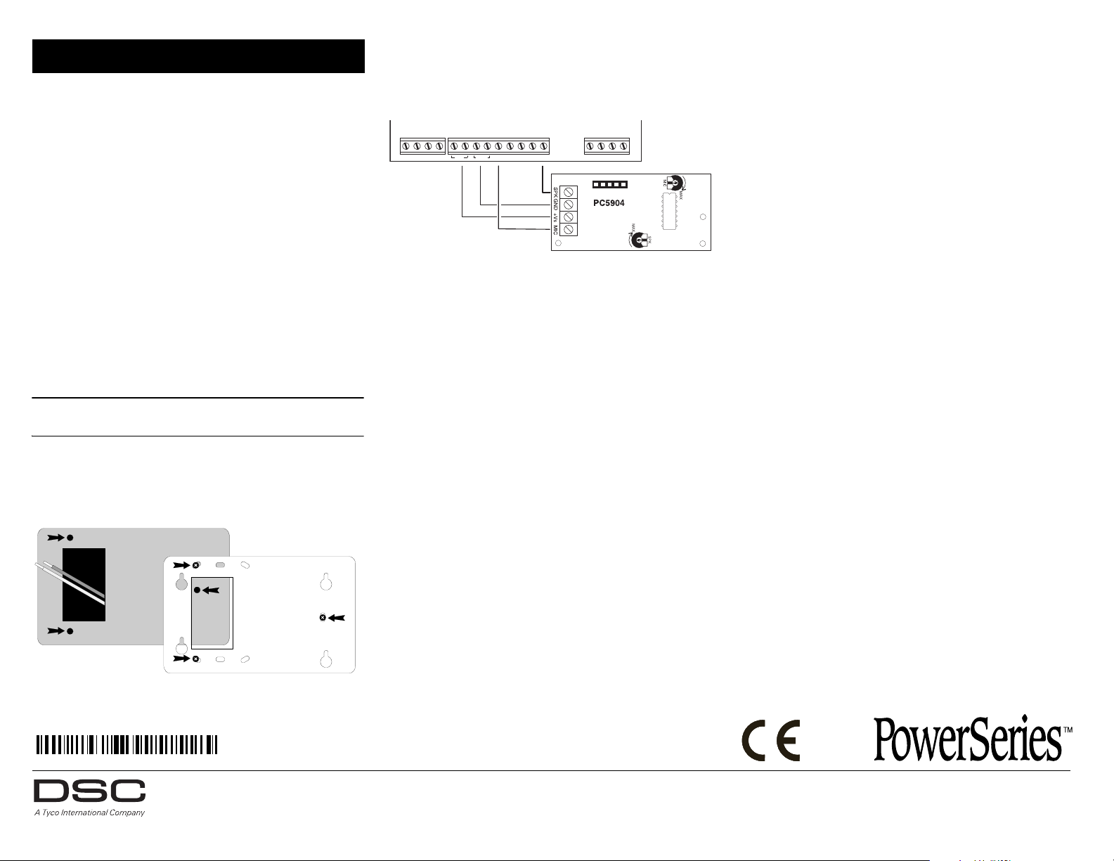
RED BLK YEL GRN AUX COM M1 M2 M3 M4 SPK RNG TIP R-1 T-1
PC5900
29001908R004
PC5904 Installation Instructions
Intercom Talk/Listen Module
This equipment shall be installed in non-hazardous locations,
by service persons only. These instructions must be used with
the PC5900 Installation Manual.
The PC5904 Central Station Talk/Listen module is used in
conjunction with the PC5900 for communication with the
central monitoring station. Each PC5904 station has a separate
microphone and speaker to transmit and receive audio input.
Monitoring station personnel can listen in and respond via the
control station loud speaker when required.
Wire each station directly to the PC5900 using shielded
22-gauge, 4-conductor wire.
Specifications
• PC5904 maximum current draw: 175mA
• Operating Temperature: -10°C to +55°C
• Relative Humidity: 93% (max.)
Mounting and Wiring Directions
IMPORTANT NOTE: Prior to installation, disconnect
power and telephone line connection.
1. Position the PC5904 backplate in the desired location and
mark the appropriate screw locations.
2. Secure the PC5904 backplate to the wall using the
supplied screws, as indicated below:
3. Wire the station to the PC5900. To wire the power, connect
the +VS to AUX and GND to COM (red = positive; black =
negative). The MIC and SPK terminals on each PC5904
must be connected to an M terminal (M1-M4) and a SPK
terminal on the PC5900 as indicated below:
NOTE: There are two AUX and COM terminals located on the
PC5900. The PC5904 can be connected to either terminal.
4. The speaker volume and microphone sensitivity can be
adjusted with the MIC and SPK potentiometers, as
indicated in the diagram above.
5. Once all wiring is complete, mount the station to the
backplate.
NOTE: It is recommended that wall anchors be used for all
mounting screws. When the wall anchors have been installed,
secure the backplate to the wall.
LIMITED WARRANTY
Digital Security Controls warrants that for a period of twelve months from the
date of purchase, the product shall be free of defects in materials and workmanship under normal use and that in fulfillment of any breach of such warranty,
Digital Security Controls shall, at its option, repair or replace the defective
equipment upon return of the equipment to its factory. This warranty applies
only to defects in parts and workmanship and not to damage incurred in shipping or handling, or damage due to causes beyond the control of Digital Security Controls such as lightning, excessive voltage, mechanical shock, water
damage, or damage arising out of abuse, alteration or improper application of
the equipment.
The foregoing warranty shall apply only to the original buyer, and is and shall be
in lieu of any and all other warranties, whether expressed or implied and of all
other obligations or liabilities on the part of Digital Security Controls. This warranty contains the entire warranty. Digital Security Controls neither assumes
responsibility for, nor authorizes any other person purporting to act on its behalf to
modify or to change this warranty, nor to assume for it any other warranty or liability concerning this product. In no event shall Digital Security Controls be liable
for any direct or indirect or consequential damages, loss of anticipated profits, loss
of time or any other losses incurred by the buyer in connection with the purchase,
installation or operation or failure of this product.
Warning: Digital Security Controls recommends that the entire system be
completely tested on a regular basis. However, despite frequent testing, and
due to, but not limited to, criminal tampering or electrical disruption, it is possible for this product to fail to perform as expected.
FCC COMPLIANCE STATEMENT
CAUTION: Changes or modifications not expressly approved by Digital Security Controls could void your authority to use this equipment.
This equipment generates and uses radio frequency energy and if not installed
and used properly, in strict accordance with the manufacturer’s instructions,
may cause interference to radio and television reception. It has been type tested
and found to comply with the limits for Class B device in accordance with the
specifications in Subpart “B” of Part 15 of FCC Rules, which are designed to
provide reasonable protection against such interference in any residential
installation. However, there is no guarantee that interference will not occur in a
particular installation. If this equipment does cause interference to television or
radio reception, which can be determined by turning the equipment off and on,
the user is encouraged to try to correct the interference by one or more of the
following measures:
• Re-orient the receiving antenna
• Relocate the alarm control with respect to the receiver
• Move the alarm control away from the receiver
• Connect the alarm control into a different outlet so that alarm control and
receiver are on different circuits.
If necessary, the user should consult the dealer or an experienced radio/television
technician for additional suggestions. The user may find the following booklet
prepared by the FCC useful: “How to Identify and Resolve Radio/Television
Interference Problems”. This booklet is available from the U.S. Government
Printing Office, Washington D.C. 20402, Stock # 004-000-00345-4.
© 2013 Tyco International Ltd. and its Respective Companies. All Rights Reserved.
Toronto, Canada www.dsc.com
Tech. Support: 1-800-387-3630 (Canada & U.S.), 905-760-3000
Printed in Canada

MUR
PLAQUE ARRIERE
RED BLK YEL GRN AUX COM M1 M2 M3 M4 SPK RNG TIP R-1 T-1
PC5900
PC5904 Instructions d'installation
Module Parler/Écouter
Cet équipement doit être installé dans des zones non
dangereuses, et seulement par des techniciens de service. Ce
manuel sera employé avec le manuel d’installation de
PC5900.
Le module PC5904 Parler /Écouter du poste central est utilisé
en conjonction avec le PC5900 pour une communication avec
la station centrale de surveillance. Chaque poste PC5904
possède un microphone et un haut-parleur séparés pour un
échange émission/réception audio. En outre, le personnel de la
station de surveillance peut communiquer avec l'utilisateur
final en écoutant lorsqu'un problème de sécurité se produit et
offrir une réponse verbale par le biais du haut-parleur du poste.
Chaque poste doit être connecté de manière autonome au
module d'interface à l'aide d'un câble blindé 4-fils
conducteurs de calibre 22.
Caractéristiques
• Appel de courant maximum du PC5904 : 175 mA
• Température de fonctionnement : -10°C à +55°C
• Humidité de fonctionnement : 93% (max.)
• Les degrés de protection du boîtier : IP30, IK04
Instructions de montage et de câblage
NOTE IMPORTANTE : Avant l'installation, débrancher tous
les puissance et raccordement aux lignes téléphoniques.
3. Câblez le poste au PC5900. Pour câbler l'alimentation,
branchez le +VS au AUX et le GND au COM (rouge =
positif ; noir = négatif). Les bornes MIC et SPK sur
chaque PC5904 doivent être connectées aux bornes M
(M1-M4) et borne SPK sur le PC5900. Consultez le
diagramme de câblage ci-dessous :
NOTE: Il y a deux bornes AUX et COM situées sur le
PC5900. Le PC5904 peut être connecté à l'une des deux
bornes.
4. Le volume du haut-parleur et la sensibilité du microphone
peuvent être réglés en tournant les potentiomètres
étiquetés MIC et SPK, comme indiqué sur le diagramme
ci-dessus.
5. Une fois que tout le câblage est achevé, fixez le poste à la
plaquette arrière.
NOTE: Nous vous suggérons d'utiliser des chevilles appro-
priées pour toutes les vis. Lorsque les chevilles ont été placées, fixez la plaquette arrière au mur.
GARANTIE LIMITÉE
Digital Security Controls pendant une période de douze mois à partir de
la date d’achat, garantit le produit contre toute défectuosité matérielle et
d’assemblage dans des conditions normales d’utilisation. Dans l’application de cette garantie, Digital Security Controls va, lorsqu’elle le juge
opportun, en cas de problèmes de fonctionnement, réparer ou remplacer
les équipements défectueux dès leur retour à son dépôt de réparation.
Cette garantie s’applique seulement aux éléments défectueux et à la
main-d’oeuvre, et non aux dommages causés lors de l’expédition ou de la
manipulation, ni aux dommages dont les causes dépassent le contrôle de
Digital Security Controls telles que la foudre, les surtensions, les chocs
mécaniques, les dégâts d’eau ou tout dommage provenant d’abus, de
modifications ou de mauvaises utilisations de l’équipement. La garantie
susdite n’est valide que pour l’acheteur original et n’est et ne sera que la
seule des garanties valables, qu’elle ait été exprimée ou implicite, remplaçant toute autre obligation ou responsabilité de la part de Digital Security Controls. La présente garantie contient la garantie au complet. Digital
Security Controls. n’autorise aucune autre personne à agir en son nom
pour modifier ou changer la présente garantie et n’en assume pas la responsabilité, ni a à assumer en son nom toute autre garantie ou responsabilité concernant le présent produit. En aucun cas, Digital Security Controls
ne pourra être tenue responsable des conséquences directes ou indirectes
de dommages relativement à la perte de profits prévus, à la perte de
temps ou à toute autre perte subie par l’acheteur en rapport avec l’achat,
l’installation et le fonctionnement ou la défaillance du présent produit.
AVERTISSEMENT : Digital Security Controls recommande que le système soit régulièrement soumis à un essai complet. Cependant, en dépit
d’essais réguliers et à cause d’interventions criminelles, pannes de courant ou autres, il est possible que le fonctionnement du produit ne soit
pas conforme aux spécifications.
Le module PC5904, type 2 est conforme aux normes: NF C
48-205, C 48-211, C 48-212, C 48-410 et aux fiches
d'interprétations associées. Les organismes certificateurs sont:
AFNOR CERTIFICATION (www.marque-nf.com) et Centre
National de Prévention et de Protection (CNPP).
1. Trouver l'emplacement désiré pour le dispositif. Placez la
plaquette arrière du PC5904 contre le mur et marquez
l'emplacement des vis.
2. Fixez la plaque arrière du PC5904 au mur à l'aide des vis
fournies. Consultez le diagramme ci-dessous :
©2013 Tyco International Ltd. et ses compagnies respectives. Tous droits réservés
Toronto, Canada www.dsc.com
Centre d’aide technique: 1-800-387-3630 (Canada & U.S.), 905-760-3000
Imprime au Canada
 Loading...