

DSC Power PC5532Z, Power PC1555RKZ, Power LCD5501Z, Power LCD5500Z, PC5508Z Instruction Manual
...Page 1

Instruction Manual
Manuel d'Instruction
Manual de Instrucción
NOTE This manual contains information on limitations regarding product use and function and informa-
tion on the limitations as to liability of the manufacturer. The entire manual should be carefully read.
NOTE Ce guide contient de l’information sur les limites de fonctionnement et d’utilisation de ce produit
ainsi que de l’information sur les limites de la responsabilité du fabricant. Vous devriez lire entièrement ce
guide avec attention.
NOTA Este manual, contiene información sobre restricciones acerca del uso y funcionamiento del pro-
ducto e información sobre las limitaciones, tal como, la responsabilidad del fabricante. Todo el manual se
debe leer cuidadosamente.
Page 2

WARNING Please Read Carefully
Note to Installers
This warning contains vital information. As the only individual in contact with
system users, it is your responsibility to bring each item in this warning to the
attention of the users of this system.
System Failures
This system has been carefully designed to be as effective as possible. There are
circumstances, however, involving fire, burglary, or other types of emergencies
where it may not provide protection. Any alarm system of any type may be compromised deliberately or may fail to operate as expected for a variety of reasons.
Some but not all of these reasons may be:
■ Inadequate Installation
A security system must be installed properly in order to provide adequate protection. Every installation should be evaluated by a security professional to ensure
that all access points and areas are covered. Locks and latches on windows and
doors must be secure and operate as intended. Windows, doors, walls, ceilings and
other building materials must be of sufficient strength and construction to provide
the level of protection expected. A reevaluation must be done during and after any
construction activity. An evaluation by the fire and/or police department is highly
recommended if this service is available.
■ Criminal Knowledge
This system contains security features which were known to be effective at the
time of manufacture. It is possible for persons with criminal intent to develop techniques which reduce the effectiveness of these features. It is important that a security system be reviewed periodically to ensure that its features remain effective and
that it be updated or replaced if it is found that it does not provide the protection
expected.
■ Access by Intruders
Intruders may enter through an unprotected access point, circumvent a sensing
device, evade detection by moving through an area of insufficient coverage, disconnect a warning device, or interfere with or prevent the proper operation of the
system.
■ Power Failure
Control units, intrusion detectors, smoke detectors and many other security
devices require an adequate power supply for proper operation. If a device operates from batteries, it is possible for the batteries to fail. Even if the batteries have
not failed, they must be charged, in good condition and installed correctly. If a
device operates only by AC power, any interruption, however brief, will render
that device inoperative while it does not have power. Power interruptions of any
length are often accompanied by voltage fluctuations which may damage electronic equipment such as a security system. After a power interruption has
occurred, immediately conduct a complete system test to ensure that the system
operates as intended.
■ Failure of Replaceable Batteries
This system’s wireless transmitters have been designed to provide several years of
battery life under normal conditions. The expected battery life is a function of the
device environment, usage and type. Ambient conditions such as high humidity,
high or low temperatures, or large temperature fluctuations may reduce the
expected battery life. While each transmitting device has a low battery monitor
which identifies when the batteries need to be replaced, this monitor may fail to
operate as expected. Regular testing and maintenance will keep the system in good
operating condition.
■ Compromise of Radio Frequency (Wireless) Devices
Signals may not reach the receiver under all circumstances which could include
metal objects placed on or near the radio path or deliberate jamming or other inadvertent radio signal interference.
■ System Users
A user may not be able to operate a panic or emergency switch possibly due to permanent or temporary physical disability, inability to reach the device in time, or
unfamiliarity with the correct operation. It is important that all system users be
trained in the correct operation of the alarm system and that they know how to
respond when the system indicates an alarm.
■ Smoke Detectors
Smoke detectors that are a part of this system may not properly alert occupants of
a fire for a number of reasons, some of which follow. The smoke detectors may
have been improperly installed or positioned. Smoke may not be able to reach the
smoke detectors, such as when the fire is in a chimney, walls or roofs, or on the
other side of closed doors. Smoke detectors may not detect smoke from fires on
another level of the residence or building.
Every fire is different in the amount of smoke produced and the rate of burning.
Smoke detectors cannot sense all types of fires equally well. Smoke detectors may
not provide timely warning of fires caused by carelessness or safety hazards such
as smoking in bed, violent explosions, escaping gas, improper storage of flammable materials, overloaded electrical circuits, children playing with matches or
arson.
Even if the smoke detector operates as intended, there may be circumstances when
there is insufficient warning to allow all occupants to escape in time to avoid
injury or death.
■ Motion Detectors
Motion detectors can only detect motion within the designated areas as shown in
their respective installation instructions. They cannot discriminate between intruders and intended occupants. Motion detectors do not provide volumetric area protection. They have multiple beams of detection and motion can only be detected in
unobstructed areas covered by these beams. They cannot detect motion which
occurs behind walls, ceilings, floor, closed doors, glass partitions, glass doors or
windows. Any type of tampering whether intentional or unintentional such as
masking, painting, or spraying of any material on the lenses, mirrors, windows or
any other part of the detection system will impair its proper operation.
Passive infrared motion detectors operate by sensing changes in temperature.
However their effectiveness can be reduced when the ambient temperature rises
near or above body temperature or if there are intentional or unintentional sources
of heat in or near the detection area. Some of these heat sources could be heaters,
radiators, stoves, barbeques, fireplaces, sunlight, steam vents, lighting and so on.
■ Warning Devices
Warning devices such as sirens, bells, horns, or strobes may not warn people or
waken someone sleeping if there is an intervening wall or door. If warning devices
are located on a different level of the residence or premise, then it is less likely that
the occupants will be alerted or awakened. Audible warning devices may be interfered with by other noise sources such as stereos, radios, televisions, air conditioners or other appliances, or passing traffic. Audible warning devices, however loud,
may not be heard by a hearing-impaired person.
■ Telephone Lines
If telephone lines are used to transmit alarms, they may be out of service or busy
for certain periods of time. Also an intruder may cut the telephone line or defeat its
operation by more sophisticated means which may be difficult to detect.
■ Insufficient Time
There may be circumstances when the system will operate as intended, yet the
occupants will not be protected from the emergency due to their inability to
respond to the warnings in a timely manner. If the system is monitored, the
response may not occur in time to protect the occupants or their belongings.
■ Component Failure
Although every effort has been made to make this system as reliable as possible,
the system may fail to function as intended due to the failure of a component.
■ Inadequate Testing
Most problems that would prevent an alarm system from operating as intended can
be found by regular testing and maintenance. The complete system should be
tested weekly and immediately after a break-in, an attempted break-in, a fire, a
storm, an earthquake, an accident, or any kind of construction activity inside or
outside the premises. The testing should include all sensing devices, keypads, consoles, alarm indicating devices and any other operational devices that are part of
the system.
■ Security and Insurance
Regardless of its capabilities, an alarm system is not a substitute for property or
life insurance. An alarm system also is not a substitute for property owners, renters, or other occupants to act prudently to prevent or minimize the harmful effects
of an emergency situation
Page 3

Pour le français voir la page 14
Para el español vea la página 28
Table of Contents
System Keypads ..................................................................................................................................... 2
Reference Sheet .................................................................................................................................... 5
About You Security System .................................................................................................................. 7
Arming (Turning On/Setting)............................................................................................................... 8
Disarming (Turning Off /Unsetting) .................................................................................................... 8
Stay Arming (Partially On / Part Set) ................................................................................................... 8
Emergency Keys .................................................................................................................................... 8
When Alarm Sounds ............................................................................................................................. 8
Intrusion (Burglar) Alarm Continuous Siren ....................................................................................... 8
Fire Alarm Pulsed Siren ......................................................................................................................... 9
Alarm Memory ...................................................................................................................................... 9
Sensor Reset .......................................................................................................................................... 9
System Test (Keypad, Siren and Battery) ............................................................................................ 9
Access Code Programming ................................................................................................................... 9
Time & Date Programming ................................................................................................................. 10
Quick Exit ............................................................................................................................................. 10
Door Chime (Entry/Exit Beeps) ..........................................................................................................10
Trouble Conditions ............................................................................................................................. 10
Bypassing ............................................................................................................................................. 10
Guidelines for Locating Smoke Detectors ......................................................................................... 11
Household Fire Safety Audit .............................................................................................................. 12
Fire Escape Planning ........................................................................................................................... 12
For Service
Central Station Information:
Account#: ___________________ Telephone#: __________________
Installer Information :
Company: ___________________ Telephone#: __________________
If you suspect a false alarm signal has been sent to the central monitoring station, call the station to avoid an unnecessary response.
1
Page 4
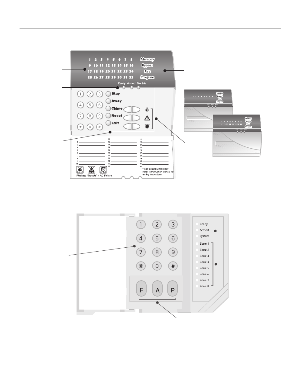
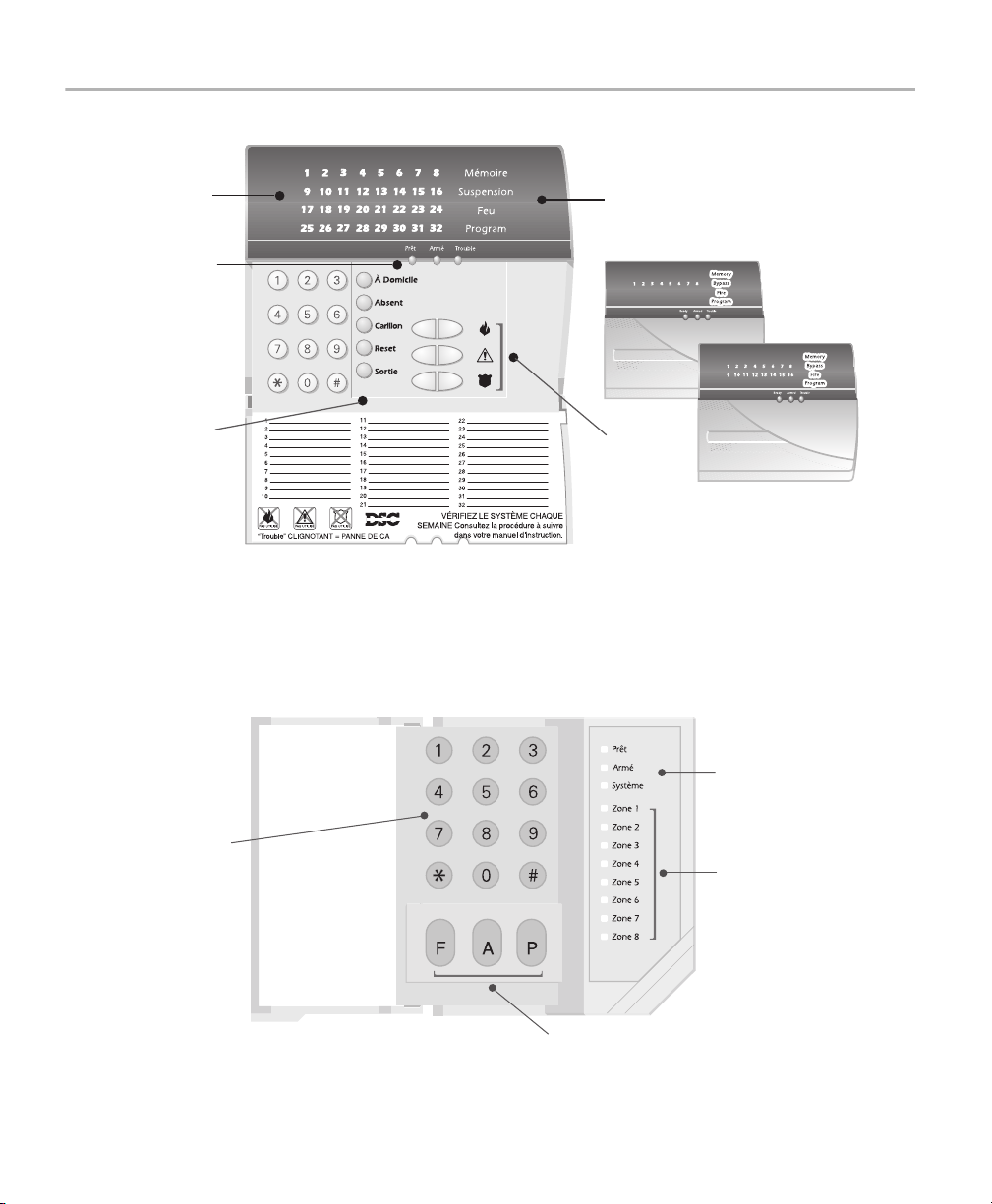
PowerSeries System Keypads
PC5532Z
Zone
Lights
Status
Lights
Function
Buttons
[
PC1555RKZ
Function
Lights
PC5508Z
PC5516Z
Emergency
Keys
Your installer may have installed one
of these LED keypads if you have 16
or fewer zones on your system. These
keypads operate in the same way as
the PC5532 keypad.
[
Status
Lights
Number
Pad
Zone
Lights
Emergency
Keys
2
Page 5
Status
Lights
Number
Pad
Function
Buttons
LCD5501Z
Envoy System Keypad
NT9005-433
LCD5500Z
Liquid
Crystal
Display (LCD)
Arrow
(Scroll)
Keys
Emergency
Keys
English
Siren
Status
Lights
Emergency
Keys
Number
Pad
[
Liquid
Crystal
Display (LCD)
[
[
Function
Buttons
3
Page 6
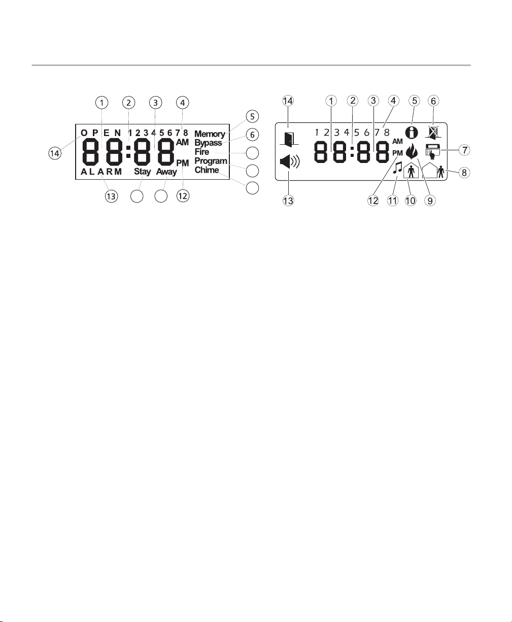
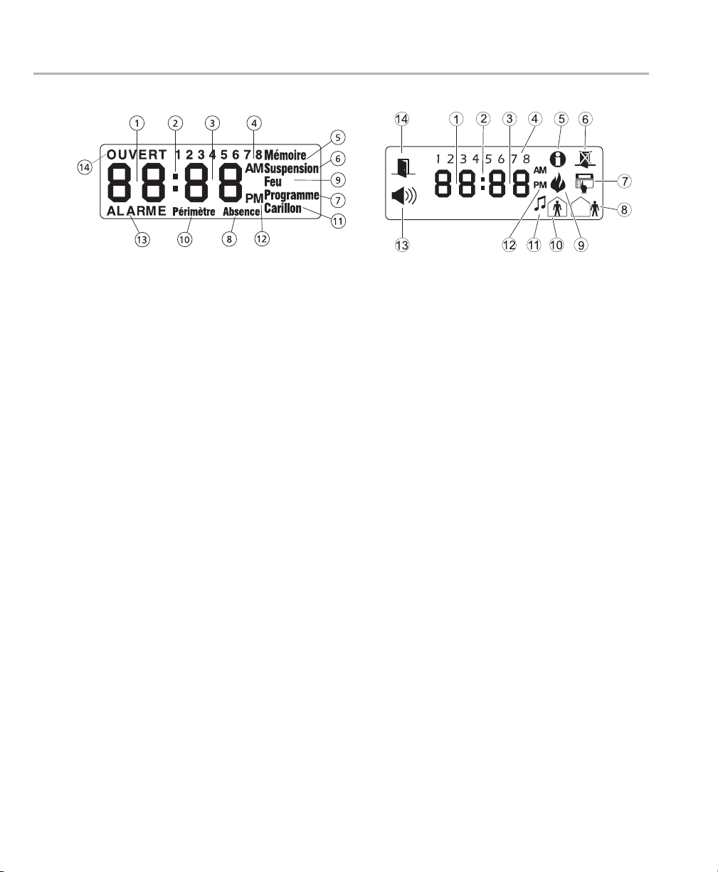
Liquid Crystal Display (LCD)
Fixed Message
9
7
810
1 Clock Digits 1, 2 – These two 7 segment clock digits indicate the hour digits when the local clock is active,
and identify the zone when the OPEN or ALARM icons are active. These two digits scroll one zone per second
from the lowest zone number to the highest when scrolling through zones.
2: (Colon) – This icon is the hours/minutes divider and will flash once a second when the local clock is active.
3 Clock Digits 3, 4 – These two 7 segment displays are the minute digits when the local clock is active.
4 1 to 8 – These numbers identify troubles when [*][2] is pressed.
5 Memory – Indicates that there are alarms in memory.
6Bypass – Indicates that there are zones automatically or manually bypassed.
7 Program – indicates that the system is in Installer’s Programming, or the keypad is busy.
11
Icon
8Away – Indicates that the panel is armed in the Away Mode. It will turn on at the beginning of the Exit Delay.
9 Fire – Indicates that there are fire alarms in memory.
10 Stay – Indicates that the panel is armed in the Stay Mode. It will turn on at the beginning of the Exit Delay.
11 Chime – This icon turns on when the chime function key (F3) is pressed to enable Door Chime on the system.
It will turn off when the chime function key (F3) is pressed again to disable Door Chime.
12 AM, PM – This icon indicates that the local clock is displaying 12 Hr. time. These icons will not be on if the
system is programmed for 24 Hr. time.
13 ALARM – This icon is used with clock digits 1 and 2 to indicate zones in alarm on the system. When a zone is
in alarm, the ALARM icon will turn on, and 7 segment displays 1 and 2 will scroll through the zones in alarm.
14 OPEN – This icon is used with clock digits 1 and 2 to indicate violated zones (not alarm) on the system. When
zones are opened, the OPEN icon will turn on, and 7 segment displays 1 and 2 will scroll through the violated
zones.
4
Page 7
Reference Sheets
Fill out the following information for future reference and store this guide in a safe place.
Access Codes
Master Code [40] : _________________________
Code Access Code Code Access Code Code Access Code Code Access Code
01 09 17 25
02 10 18 26
03 11 19 27
04 12 20 28
05 13 21 29
06 14 22 30
07 15 23 31
08 16 24 32
English
Sensor /Zone Information
Enabled?
❏ [F] FIRE ❏ [A] AUXILIARY ❏ [P] PANIC
The Exit Delay Time is _______ seconds.
The Entry Delay Time is _______ seconds.
5
Page 8

Sensor Protected Area Sensor Type Sensor Protected Area Sensor Type
01 33
02 34
03 35
04 36
05 37
06 38
07 39
08 40
09 41
10 42
11 43
12 44
13 45
14 46
15 47
16 48
17 49
18 50
19 51
20 52
21 53
22 54
23 55
24 56
25 57
26 58
27 59
28 60
29 61
30 62
31 63
32 64
6
Page 9

About Your Security System
Your DSC Security System has been designed to provide you with the greatest possible flexibility and convenience. Read this
manual carefully and have your installer instruct you on your system's operation and on which features have been implemented in your system. All users of this system should be equally instructed in its use. Fill out the “System Information” page with
all of you zone information and access codes and store this manual in a safe place for future reference.
Fire Detection
This equipment is capable of monitoring fire detection devices such as smoke detectors and providing a warning if a fire condition is detected. Good fire detection depends on having adequate number of detectors placed in appropriate locations. This
equipment should be installed in accordance with NFPA 72 (N.F.P.A., Batterymarch Park, Quincey MA 02269). Carefully review
the Family Escape Planning guidelines in this manual.
NOTE: Your installer must enable the fire detection portion of this equipment before it becomes functional.
Tes ting
To insure that your system continues to function as intended, you must test your system weekly. Please refer to the “System
Test” section in this manual. If your system does not function properly, call your installing company for service.
Monitoring
This system is capable of transmitting alarms, troubles and emergency information over telephone lines to a central station. If
you inadvertently initiate an alarm, immediately call the central station to prevent an unnecessary response.
NOTE: The monitoring function must be enabled by the installer before it becomes functional.
General System Operation
Your security system is made up of a DSC control panel, one or more keypads and various sensors and detectors. The control
panel will be mounted out of the way in a utility closet or in a basement. The metal cabinet contains the system electronics,
fuses and stand-by battery. There is normally no reason for anyone but the installer or service professional to have access to
the control panel.
All the keypads have an audible indicator and command entry keys. The LED keypads have a group of zone and system status
lights. The LCD keypad has an alphanumeric liquid crystal display (LCD).
The keypad is used to send commands to the system and to display the current system status. The keypad(s) will be mounted
in a convenient location inside the protected premises close to the entry/exit door(s).
The security system has several zones of area protection and each of these zones will be connected to one or more sensors
(motion detectors, glassbreak detectors, door contacts, etc.). A sensor in alarm will be indicated by the corresponding zone
lights flashing on a LED keypad or by written messages on the LCD keypad.
English
IMPORTANT NOTICE
A security system cannot prevent emergencies. It is only intended to alert you and – if included – your central station of an
emergency situation. Security systems are generally very reliable but they may not work under all conditions and they are not
a substitute for prudent security practices or life and property insurance. Your security system should be installed and serviced
by qualified security professionals who should instruct you on the level of protection that has been provided and on system
operations.
7
Page 10

Arming (Turning On/Setting)
Close all sensors (i.e. stop motion and close doors). The Ready ( ) indicator should be on.
To arm, press and hold the
and the keypad will beep. You now have ____ seconds to leave the premises. To cancel the arming sequence, enter your
access code.
Away key for 2 seconds and/or enter your Access Code. The Armed ( ) indicator will turn on,
Arming Error
An error tone will sound if the system is unable to arm. This will happen if the system is not ready to arm (i.e. sensors are
open), or if an incorrect user code has been entered. If this happens, ensure all sensors are secure, press and try again.
Disarming (Turning Off /Unsetting)
Enter your access code to disarm anytime the system is armed (i.e. Armed ( ) indicator is on).
The keypad will beep if you walk through the entry door. You must enter your code within ___ seconds to avoid an alarm
condition.
Disarming Error
If your code is not valid, the system will not disarm and a 2-second error tone will sound. If this happens, press and
try again.
Stay Arming (Partially On / Part Set)
Stay arming will bypass the interior protection (i.e. motion sensors) and arm the perimeter of the system (i.e. doors and
windows). Close all sensors (i.e. stop motion and close doors). The Ready ( ) indicator should be on. Ask your alarm company if this function is available on your system.
Press and hold the Stay key for 2 seconds, and/or enter your Access Code, and do not leave the premises.
The Armed ( ) indicator and Bypass or System indicator will turn on. The system will automatically bypass certain interior
sensors (i.e. motion sensors).
Emergency Keys
The Fire, Auxiliary and Panic Emergency keys will NOT function unless programmed and enabled by the installer.
Press the
keys are available on your system.
F, A or P key for 2 seconds to generate a Fire, Auxiliary or Panic alarm. Ask your alarm company if the emergency
When Alarm Sounds
The system can generate 2 different alarm sounds:
Continuous Siren = Instrusion (Burglary Alarm)
Temporal / Pulsed Siren = Fire Alarm
Intrusion (Burglar) Alarm Continuous Siren
If you are unsure of the source of the alarm approach with caution !
If the alarm was accidental, enter your Access Code to silence the alarm. Call your central station to avoid a dispatch.
8
Page 11
Fire Alarm Pulsed Siren
Follow your emergency evacuation plan immediately!
If the fire alarm was accidental (i.e. burned toast, bathroom steam, etc.), enter your Access Code to silence the alarm. Call
your central station to avoid a dispatch. Ask your alarm company if your system has been equipped with fire detection.
To reset the detectors, see the Sensor Reset section below.
Alarm Memory
When an alarm occurs, the Memory or System indicator (and Fire indicator, if applicable) will turn on.
To view which sensor(s) generated the alarm, press . The Memory or System indicator and corresponding sensor
number will flash (i.e. sensor 3).
For the LCD5500 keypad use the scroll keys to view the sensors in alarm memory.
Press to exit. To clear the memory, arm and disarm the system.
If an alarm sounded while armed, the keypad will automatically go to alarm memory when you disarm the system. In this
instance, you should approach with caution, as the intruder may still be within the building/premises.
Sensor Reset
Certain sensors, after having detected an alarm condition, require a reset to exit the alarm condition (i.e. glass break sensors, smoke detectors, etc.). Ask your alarm company if this function is required on your system.
To reset the detectors, press and hold the
If a sensor fails to reset, it may still be detecting an alarm condition. If the sensor reset is successful, the alarm is cancelled.
If unsuccessful, the alarm will reactivate or continue.
Reset key for 2 seconds or press .
System Test (Keypad, Siren and Battery)
If you are going to perform a System Test, call your Monitoring Station to inform them when you begin and also
when you end the test.
Press , plus your Master Access Code. The Program or System indicator will flash and the Armed ( ) indicator will
turn on.
Press to initiate the 2-second test (siren and keypad will activate). Press to exit.
English
Access Code Programming
In addition to the Master Access Code, you can program up to 32 additional User Access codes. Press , plus your Master
Access Code. The Program or System indicator will begin to flash, and the Armed ( ) indicator will turn on.
Enter the 2-digit number to programmed (i.e. 06 for user access code 6; enter 40 for the Master Access Code). The Ready
( ) indicator will turn on.
When using the LCD5500, use the scroll keys to find the specific code and press to select. Enter the new 4-digit
access code, or press to erase it. When programming is complete, enter another 2-digit code to program or press
to exit.
For systems using multiple partitions/areas, access codes can be assigned to specific or multiple partitions/areas. Please contact your alarm company for details.
9
Page 12

Time & Date Programming
Press , plus your Master Access Code. The Program or System indicator will begin to flash, and the Armed ( ) indicator will turn on.
Press to select Time and Date. The Ready ( ) indicator will turn on.
When using the LCD5500, use the scroll keys to find the menu option and press to select.
Enter the time in 24-hr format (HH:MM), followed by the date (MM:DD:YY). Press to exit programming.
Quick Exit
If the system is armed and you need to exit, use the Quick Exit function to avoid disarming and rearming the system. Press
and hold the
Exit key for 2 seconds or press . You now have 2 minutes to leave the premises through your exit
door. When the door is closed again, the remaining exit time is cancelled.
Door Chime (Entry/Exit Beeps)
To turn the door chime function on or off, press and hold the Chime key for 2 seconds or press .
Trouble Conditions
When a trouble condition is detected, the Trouble ( ) or System indicator will turn on, and the keypad will beep every 10
seconds. Press the key to silence the beeps. Press to view the trouble condition. The Trouble ( ) or System
indicator will flash. The corresponding trouble will be represented by numbers 1-8.
LED/DIGIT
Trouble Condition Comments Action
1 Service Required Call for service
2
Loss of AC Power
3 Telephone Line Fault The system has detected that the telephone line is cut. Call for service
4
Failure to Communicate
5
Sensor (or Zone) Fault
6
Sensor (or Zone) Tamper
7
Sensor (or Zone) Low Battery
8
Loss of Time & Date
If the building and/or neighborhood has lost electrical power, the
system will continue to operate on battery for several hours.
The system attempted to communicate with the monitoring station, but failed. This may be due to Trouble 3.
The system is experiencing difficulties with one or more sensors
on the system.
The system has detected a tamper condition with one or more
sensors on the system.
If the system has been equipped with wireless sensors, one or
more has reported a low battery condition.
If complete power was lost (AC and Battery), the time and date
will need to be re-programmed.
Call for service
Call for service
Call for service
Call for service
Call for service
Call for service
Bypassing
To bypass a sensor, press . The bypass or system indicator will flash.
Enter the 2-digit number for the sensor to be bypassed (i.e. 03 for sensor number 3). To bypass an additional sensor, enter
another 2-digit entry for that sensor.
For the LCD5500, use the scroll keys to find the specific sensor and press to bypass.
Press to exit. The bypass or system indicator will stay on.
10
Page 13
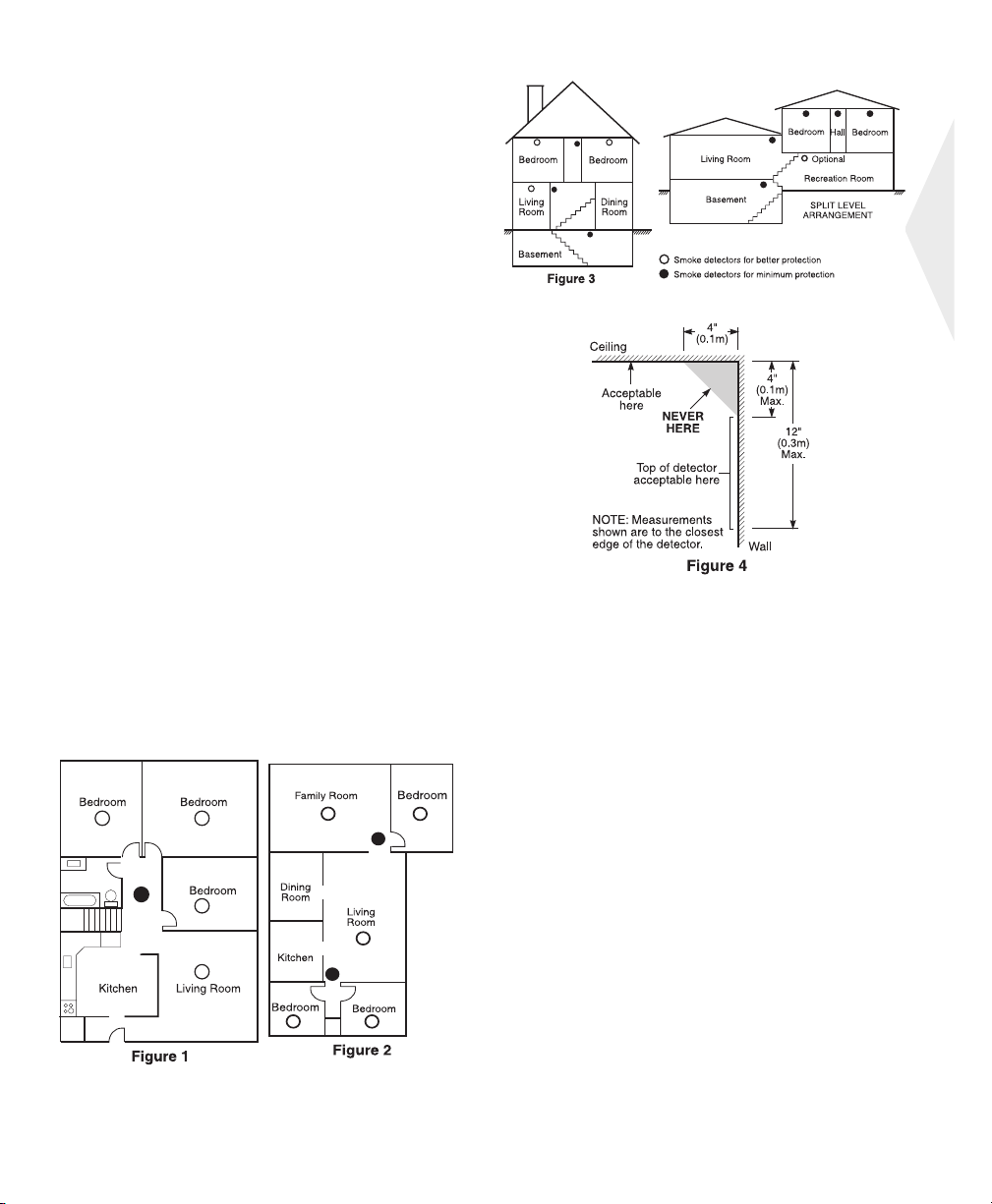
Guidelines for Locating Smoke Detectors
Research has shown that all hostile fires in homes generate smoke to a greater or lesser extent. Experiments with
typical fires in homes indicate that detectable quantities
of smoke precede detectable levels of heat in most cases.
For these reasons, smoke alarms should be installed outside of each sleeping area and on each storey of the
home.
The following information is for general guidance only
and it is recommended that local fire codes and regulations be consulted when locating and installing smoke
alarms.
It is recommended that additional smoke alarms beyond
those required for minimum protection be installed. Additional areas that should be protected include: the basement; bedrooms, especially where smokers sleep; dining
rooms; furnace and utility rooms; and any hallways not
protected by the required units.
On smooth ceilings, detectors may be spaced 9.1m (30
feet) apart as a guide. Other spacing may be required depending on ceiling height, air movement, the presence of
joists, uninsulated ceilings, etc. Consult National Fire
Alarm Code NFPA 72, CAN/ULC-S553-M86 or other appropriate national standards for installation recommendations.
Do not locate smoke detectors at the top of peaked or
gabled ceilings; the dead air space in these locations may
prevent the unit from detecting smoke.
Avoid areas with turbulent air flow, such as near doors,
fans or windows. Rapid air movement around the detector may prevent smoke from entering the unit.
Do not locate detectors in areas of high humidity.
Do not locate detectors in areas where the temperature
rises above 38
Smoke detectors should always be installed in accordance
with NFPA 72, the National Fire Alarm Code. Smoke detectors should always be located in accordance with:
1: ‘Smoke detectors shall be installed outside of each sep-
arate sleeping area in the immediate vicinity of the bedrooms and on each additional storey of the family living
unit, including basements and excluding crawl spaces
and unfinished attics. In new construction, a smoke detector also shall be installed in each sleeping room’.
2: ’Split level arrangement: Smoke detectors are required
where shown. Smoke detectors are optional where a
door is not provided between living room and recreation
room’.
oC
(100oF) or falls below 5oC (41oF).
English
11
Page 14

Household Fire Safety Audit
Read this section carefully for important information about fire safety.
Most fires occur in the home. To minimize this danger, we recommend that a household fire safety audit be conducted and
a fire escape plan be developed.
1. Are all electrical appliances and outlets in a safe condition? Check for frayed cords, overloaded lighting circuits,
etc. If you are uncertain about the condition of your electrical appliances or household service, have a professional evaluate these units.
2. Are all flammable liquids stored safely in closed containers in a well-ventilated cool area? Cleaning with flammable liquids should be avoided.
3. Are fire-hazardous materials (matches) well out of reach of children?
4. Are furnaces and wood-burning appliances properly installed, clean and in good working order? Have a professional evaluate these appliances.
Fire Escape Planning
There is often very little time between the detection of a fire and the time it becomes deadly. It is thus very important that a family escape plan be developed and rehearsed.
1. Every family member should participate in developing the escape plan.
2. Study the possible escape routes from each location within the house. Since many fires occur at night, special
attention should be given to the escape routes from sleeping quarters.
3. Escape from a bedroom must be possible without opening the interior door.
Consider the following when making your escape plans:
• Make sure that all border doors and windows are easily opened. Ensure that they are not painted shut, and that
their locking mechanisms operate smoothly.
• If opening or using the exit is too difficult for children, the elderly or handicapped, plans for rescue should be
developed. This includes making sure that those who are to perform the rescue can promptly hear the fire warning signal.
• If the exit is above the ground level, an approved fire ladder or rope should be provided as well as training in its
use.
• Exits on the ground level should be kept clear. Be sure to remove snow from exterior patio doors in winter; out-
door furniture or equipment should not block exits.
• Each person should know of a predetermined assembly point where everyone can be accounted for (e.g., across
the street or at a neighbor’s house). Once everyone is out of the building, call the Fire Department.
• A good plan emphasizes quick escape. Do not investigate or attempt to fight the fire, and do not gather belong-
ings or pets as this wastes valuable time. Once outside, do not re-enter the house. Wait for the fire department.
• Write the fire escape plan down and rehearse it frequently so that should an emergency arise, everyone will
know what to do. Revise the plan as conditions change, such as the number of people in the home, or if there
are changes to the building’s construction.
• Make sure your fire warning system is operational by conducting weekly tests. If you are unsure about system
operation, contact your installing dealer.
• We recommend that you contact your local fire department and request further information on fire safety and
escape planning. If available, have your local fire prevention officer conduct an in-house fire safety inspection.
12
Page 15

Limited Warranty
Digital Security Controls Ltd. warrants the original purchaser that for a period of
twelve months from the date of purchase, the product shall be free of defects in
materials and workmanship under normal use. During the warranty period, Digital Security Controls Ltd. shall, at its option, repair or replace any defective
product upon return of the product to its factory, at no charge for labour and
materials. Any replacement and/or repaired parts are warranted for the remainder of the original warranty or ninety (90) days, whichever is longer. The original purchaser must promptly notify Digital Security Controls Ltd. in writing that
there is defect in material or workmanship, such written notice to be received in
all events prior to expiration of the warranty period. There is absolutely no warranty on software and all software products are sold as a user license under the
terms of the software license agreement included with the product. The Customer assumes all responsibility for the proper selection, installation, operation
and maintenance of any products purchased from DSC. Custom products are
only warranted to the extent that they do not function upon delivery. In such
cases, DSC can replace or credit at its option.
International Warranty
The warranty for international customers is the same as for any customer within
Canada and the United States, with the exception that Digital Security Controls
Ltd. shall not be responsible for any customs fees, taxes, or VAT that may be
due.
Warranty Procedure
To obtain service under this warranty, please return the item(s) in question to the
point of purchase. All authorized distributors and dealers have a warranty program. Anyone returning goods to Digital Security Controls Ltd. must first obtain
an authorization number. Digital Security Controls Ltd. will not accept any shipment whatsoever for which prior authorization has not been obtained.
Conditions to Void Warranty
This warranty applies only to defects in parts and workmanship relating to normal use. It does not cover:
• damage incurred in shipping or handling;
• damage caused by disaster such as fire, flood, wind, earthquake or lightning;
• damage due to causes beyond the control of Digital Security Controls Ltd.
such as excessive voltage, mechanical shock or water damage;
• damage caused by unauthorized attachment, alterations, modifications or foreign objects;
• damage caused by peripherals (unless such peripherals were supplied by Digital Security Controls Ltd.);
• defects caused by failure to provide a suitable installation environment for the
products;
• damage caused by use of the products for purposes other than those for which
it was designed;
• damage from improper maintenance;
• damage arising out of any other abuse, mishandling or improper application of
the products.
Items Not Covered by Warranty
In addition to the items which void the Warranty, the following items shall not
be covered by Warranty: (i) freight cost to the repair centre; (ii) products which
are not identified with DSC's product label and lot number or serial number; (iii)
products disassembled or repaired in such a manner as to adversely affect performance or prevent adequate inspection or testing to verify any warranty claim.
Access cards or tags returned for replacement under warranty will be credited or
replaced at DSC's option. Products not covered by this warranty, or otherwise
out of warranty due to age, misuse, or damage shall be evaluated, and a repair
estimate shall be provided. No repair work will be performed until a valid purchase order is received from the Customer and a Return Merchandise Authorisation number (RMA) is issued by DSC's Customer Service.
Digital Security Controls Ltd.’s liability for failure to repair the product under
this warranty after a reasonable number of attempts will be limited to a replacement of the product, as the exclusive remedy for breach of warranty. Under no
circumstances shall Digital Security Controls Ltd. be liable for any special, incidental, or consequential damages based upon breach of warranty, breach of contract, negligence, strict liability, or any other legal theory. Such damages include,
but are not limited to, loss of profits, loss of the product or any associated equipment, cost of capital, cost of substitute or replacement equipment, facilities or
services, down time, purchaser’s time, the claims of third parties, including customers, and injury to property. The laws of some jurisdictions limit or do not
allow the disclaimer of consequential damages. If the laws of such a jurisdiction
apply to any claim by or against DSC, the limitations and disclaimers contained
here shall be to the greatest extent permitted by law. Some states do not allow
the exclusion or limitation of incidental or consequential damages, so that the
above may not apply to you.
Disclaimer of Warranties
This warranty contains the entire warranty and shall be in lieu of any and all
other warranties, whether expressed or implied (including all implied warranties
of merchantability or fitness for a particular purpose) and of all other obligations
or liabilities on the part of Digital Security Controls Ltd. Digital Security Controls Ltd. neither assumes responsibility for nor authorizes any other person purporting to act on its behalf to modify or to change this warranty, nor to assume
for it any other warranty or liability concerning this product.
This disclaimer of warranties and limited warranty are governed by the laws of
the province of Ontario, Canada.
WARNING: Digital Security Controls Ltd. recommends that the entire system
be completely tested on a regular basis. However, despite frequent testing, and
due to, but not limited to, criminal tampering or electrical disruption, it is possible for this product to fail to perform as expected.
Out of Warranty Repairs
Digital Security Controls Ltd. will at its option repair or replace out-of-warranty
products which are returned to its factory according to the following conditions.
Anyone returning goods to Digital Security Controls Ltd. must first obtain an
authorization number. Digital Security Controls Ltd. will not accept any shipment whatsoever for which prior authorization has not been obtained.
Products which Digital Security Controls Ltd. determines to be repairable will
be repaired and returned. A set fee which Digital Security Controls Ltd. has predetermined and which may be revised from time to time, will be charged for
each unit repaired.
13
Page 16

ATTENTION à lire attentivement
Note pour les installateurs
Cette mise en garde contient des informations vitales. En tant que seul individu en
contact avec les utilisateurs du système, c’est à vous qu’incombe la responsabilité
d’attirer l’attention des utilisateurs du système sur chaque élément de cette mise en
garde.
Pannes de Système
Ce système à été soigneusement conçu pour être aussi efficace que possible. Toutefois, dans des circonstances, où il y a feu, cambriolage ou autre genre d’urgences,
il ne peut pas fournir de protection. Tout système d’alarme quel qu’il soit peut être
saboté ou peut ne pas fonctionner comme prévu pour plusieurs raisons. Certaines
de ces raisons sont notamment :
■ Mauvaise Installation
Un système de sécurité doit être correctement installé pour fournir une protection
adéquate. Chaque installation doit être évaluée par un professionnel de la sécurité
pour s’assurer que tous points d’accès et aires sont couvertes. Serrures et loquets
sur les fenêtres et portes doivent être bien fermés et fonctionner comme prévu. Les
matériels de construction des fenêtres, portes, murs, plafonds et autres doivent
assez solides pour assurer le niveau de protection attendue. Une réévaluation doit
être effectuée pendant et après toute construction. Une évaluation par les sapeurspompiers et/ou les services de police est grandement recommandée si ce service
est offert.
■ Connaissances Criminelles
Ce système contient des fonctions de sécurité reconnues efficaces au moment de la
fabrication. Il est possible que des personnes ayant des intentions criminelles
élaborent des techniques qui réduisent l’efficacité de ces fonctions. Il est important
qu’un système sécurité soit réexaminé périodiquement pour assurer que ces fonctions restent fonctionnelles et pour les actualiser ou les remplacer si elles
n’assurent plus la protection attendue.
■ Accès par des Intrus
Des intrus peuvent entrer par un point d’accès non protégé en contournant une
unité de détection, échapper à une détection en se déplaçant dans une zone à couverture insuffisante, déconnecter une unité d’alerte, ou interférer avec le système
ou empêcher son fonctionnement normal.
■ Panne de Courant
Les unités de Contrôle, les détecteurs d’intrusion, les détecteurs de fumée et bien
d’autres dispositifs de sécurité nécessitent une alimentation électrique pour fonctionner normalement. Si un dispositif fonctionne à partir de piles, il est possible
que les piles faiblissent. Même si les piles ne sont pas faibles, elles doivent être
changées, en bonne condition et installées correctement. Si un dispositif ne fonctionne que par courant électrique, toute interruption, même brève, rendra ce dispositif inopérant pendant la durée de la coupure de courant. Les coupures de
courant, quelle qu’en soit la durée, sont souvent accompagnées par des fluctuations
de voltage qui peuvent endommager l’équipement électronique tel qu’un système
de sécurité. Après qu’une coupure de courant s’est produite, effectuez immédiatement un test complet du système pour vous assurer que le système fonctionne correctement
■ Panne de Piles Remplaçables
Les transmetteurs sans fils de ce système ont été conçus pour fournir plusieurs
années d’autonomie de piles sous des conditions normales. La durée de vie de la
pile dépend de l’environnement du dispositif, de utilisation et du type de pile. Les
conditions ambiantes telles que l’humidité élevée, des températures très élevée ou
très bases, ou de grosses différences de température peuvent réduire la durée de vie
de la pile. Bien que chaque dispositif de transmission possède un dispositif de surveillance de pile faible et qu’il indique quand les piles ont besoin d’être remplacée,
il peut ne pas fonctionner comme prévu. Des tests et un entretien régulier garderont
le système dans de bonne condition de fonctionnement.
■ Limites de fonctionnement des Dispositifs de Fréquence Radio (Sans
Fils)
Les signaux peuvent ne pas atteindre le récepteur dans toutes les circonstances qui
pourraient inclure objets métalliques placés sur ou à côté du chemin radio ou blocage délibéré ou autre interférence du signal radio commis par inadvertance.
■ Les Utilisateurs du Système
Un utilisateur peut ne pas être en mesure de faire fonctionner un interrupteur de
panique ou d’urgence à cause d’une invalidité permanente ou temporaire, d’une
incapacité d’atteindre le dispositif à temps, ou d’un manque de connaissance de la
bonne fonction. Il est important que tous les utilisateurs du système soient formés
sur le bon fonctionnement du système d’alarme pour qu’ils sachent comment réa-
gir quand le système indique une alarme.
■ Détecteurs de Fumée
Les détecteurs de fumée qui font partie du système peuvent ne pas bien alerter les
occupants d’un endroit en feu pour un certains nombre de raisons, en voici
quelques une. Le détecteurs de fumée peuvent avoir été mal installés ou position-
nés. La fumée peut ne pas pouvoir atteindre le détecteurs de fumée, par exemple :
un incendie dans une cheminée, murs ou toits, ou de l’autre côté de portes fermées.
Les détecteurs de fumée peuvent ne pas détecter la fumée provenant d’incendies à
un autre niveau de la résidence ou du bâtiment.
Tous les incendies différent par la quantité de fumée produite et le taux de combustion. Les détecteurs de fumée ne peuvent pas détecter de la même manière tous les
types d’incendies. Les détecteurs de fumée ne fournissent pas d’avertissement
opportun d’un incendie causé par une imprudence ou un manque de sécurité tels
que fumer dans le lit, explosions violentes, fuites de gaz, mauvais rangement de
produits inflammables, circuits électriques surchargés, enfants jouant avec des allumettes.
Même si le détecteur de fumée fonctionne comme prévu, dans certaines circonstances il n’y a pas assez de préavis pour permettre à tous les occupants de s’enfuir
à temps pour éviter blessure ou mort.
■ Détecteurs de mouvement
Les détecteurs de mouvement ne peuvent détecter le mouvement que dans les
zones désignées, conformément aux instructions d’installation. Ils ne peuvent pas
distinguer entre intrus et occupants. Les détecteurs de mouvement ne fournissent
pas de protection de zone volumétrique. Ils ont de multiples rayons de détection et
les mouvements ne peuvent être détectés que dans des zones non obstruées et couvertes par ces rayons. Ils ne peuvent détecter les mouvements qui se produisent
derrière les murs, plafonds, sol, portes fermées, cloisons vitrées, portes vitrées ou
fenêtres. Tout type de problème qu’il soit intentionnel ou non tels camouflage,
peinture ou vaporisation de matériel sur les lentilles, miroirs, fenêtres ou toute
autre partie du système de détection l’empêchera de son fonctionner normalement.
Les Détecteurs de mouvement à infra-rouge passif fonctionnent en détectant les
changements de température. Cependant leur fonctionnement peut être inhibé
quand la température ambiante s’approche ou dépasse la température du corps ou
s’il y a des sources de chaleur intentionnelles ou non intentionnelles dans de la
zone de détection ou à côté de celle-ci. Quelques une de ces sources de chaleur
peuvent être chauffages, radiateurs, fours, barbecues, cheminées, lumière du soleil,
éclairages, etc.
■ Dispositifs d’Avertissement
Les dispositifs d’avertissement tels que sirènes, cloches, klaxons ou lumières stroboscopiques n’avertissent pas les gens ou ne réveillent pas quelqu’un qui dort s’il y
a un mur ou une porte fermée. Si les dispositifs d’avertissement sont placés à un
autre niveau de la résidence ou du local, alors il est que probable que les occupants
ne seront pas alertés ou réveillés. Les dispositifs d’avertissement audibles peuvent
interférer avec d’autres sources de bruit tels stéréo, radios, télévisions, climatisations ou autres unités électriques, ou la circulation. Les dispositifs d’avertissement
audibles, même bruyants, ne peuvent pas être entendus par une personne malentendante.
■ Lignes Téléphoniques
Si les lignes téléphoniques sont utilisées pour transmettre des alarmes, elles peuvent être hors d’usage ou occupées pendant une certaine période de temps. Un
intrus peut également couper la ligne téléphonique ou provoquer son dérangement
par des moyens plus sophistiqués parfois difficiles à détecter.
■ Insuffisance de temps
Ils peut y avoir des circonstances où le système fonctionne comme prévu, mais où
les occupants ne seront pas protégés à cause de leur incapacité à répondre aux
avertissements dans un temps alloué. Si le système est connecté à un poste de surveillance, l’intervention peut ne pas arriver à temps pour protéger les occupants ou
leurs biens.
■ Panne d’un élément
Bien que tout les efforts ont été faits pour rendre le système aussi fiable que possible, le système peut mal fonctionner à cause de la panne d’un élément.
■ Test Insuffisant
La plupart des problèmes qui pourraient empêcher un système d’alarme de fonctionner normalement peuvent être découverts en testant et entretenant le système
régulièrement. L’ensemble du système devrait être testé hebdomadairement et
immédiatement après une entrée par effraction, une tentative d’entrée par effraction, un incendie, une tempête, un tremblement de terre, un accident ou toute sorte
de construction à l’intérieur des lieux. Le test doit comporter tous les dispositifs de
détection, claviers, consoles, dispositifs d’indication d’alarme et tout autre dispositif de fonctionnement qui font partie du système.
■ Sécurité et Assurance
Sans tenir compte de ses capacités, un système d’alarme n’est pas un substitut
d’assurance sur la propriété ou d’assurance vie. Un système d’alarme n’est pas un
substitut de propriétaire, locataires ou autres occupants pour agir prudemment afin
d’empêcher ou de minimiser les effets nuisibles d’une situation d’urgence.
14
Page 17

Table des matières
Blocs de Touche de Systeme............................................................................................................... 16
Feuille de référence ............................................................................................................................ 19
Votre Système de Sécurité.................................................................................................................. 21
Armement (Mise en marche) ............................................................................................................. 22
Désarmement (Désactivation) ........................................................................................................... 22
Armement à domicile (Partiellement activé) .................................................................................... 22
Touches d’urgence .............................................................................................................................. 22
Si l'alarme retentit .............................................................................................................................. 22
Alarme d’intrusion (cambriolage) sirène continue ........................................................................... 23
Alarme incendie sirène pulsée............................................................................................................ 23
Mémoire d'alarme .............................................................................................................................. 23
Réinitialisation des détecteurs .......................................................................................................... 23
Essai de système (clavier, sirène et batterie) .................................................................................... 23
Programmation des codes d’accès .................................................................................................... 23
Programmation de la date et de l'heure ........................................................................................... 24
Sortie Rapide ....................................................................................................................................... 24
Carillon de porte (Tonalités d'entré/sortie) ...................................................................................... 24
Problèmes ............................................................................................................................................ 24
Suspension .......................................................................................................................................... 24
Directives pour la localisation des détecteurs de fumée ................................................................. 25
Incendie domestique vérification de la sécurité .............................................................................. 26
Plan d'évacuation en cas d'incendie ................................................................................................. 26
Pour l’entretien:
Renseignements relatifs à la station centrale:
Compte no :___________________ Téléphone.: __________________
Renseignements relatifs à l'installateur :
Compagnie : ___________________ Téléphone.: __________________
Si vous pensez qu'une fausse alarme d'incendie a été envoyée à la station de surveillance, appellez la station pour
éviter une réponse inutile.
15
Page 18
Blocs de Touche de Systeme PowerSeries
PC5532Z
Témoin
Lumineaux
des zones
Voyants du
système
Touches
de fonction
Indicateurs
de fonction
PC5508Z
PC5516Z
[
Touches
d'urgence
Votre installateur a peut-être installé
l'un de ces claviers DEL si vous avez un
maximum de 16 zones sur votre système. Ces claviers fonctionnent de la
même manière que le clavier PC5532.
PC1555RKZ
Clavier
numérique
[
Touches
d'urgence
16
Voyants du
système
Témoin
lumineaux
des zones
Page 19

LCD5501Z
LCD5500Z
Voyants
du système
Clavier
numérique
Touches
de fonction
Bloc de Touche de Systeme Envoy
Sirène
Voyants
du système
A Domicile
Absent
Carillon
Reset
Sortie
NT9005-433
[
Entrez code pour
Armer systeme
A Domicile
Absent
Carillon
Reset
Sortie
Affichage
(ACL)
Affichage
(ACL)
Touches de
défilement
Touches
d'urgence
Français
Touches
d'urgence
Clavier
numérique
[
[
Touches
de fonction
17
Page 20
ACL
Message Fixe
1 Afficheur à 7 segments (positions 1 et 2) : ces deux chiffres indiquent l'heure lorsque l'horloge locale est
activée et ils identifient la zone lorsque l'icône "(OUVERT)" ou "(ALARME)" est affichée. Lorsqu’on fait défiler
les zones, elles sont affichées tour à tour à intervalles d'une seconde (du plus petit au plus grand nombre).
2 : (deux points) : cette icône sépare l'affichage des heures et des minutes lorsque l'horloge est activée.
3 Afficheur à 7 segments (positions 3 et 4) : ces deux chiffres indiquent les minutes lorsque l'horloge locale est
activée.
4
1 à 8
: ces icônes sont utilisées pour identifier les troubles lorsque la fonction [✱] [2] est utilisée.
5Mémoire : cette icône indique que des alarmes de vol sont en mémoire.
6 Suspension : cette icône indique que des zone ont été manuellement ou automatiquement suspendues.
7 Programme : cette icône indique que le système est dans le mode de programmation de l'installateur ou que le
clavier est occupé.
Icône
8Absence : cette icône indique que le système est armé en mode F2 (Absent), elle s'allume au début du délai de
sortie.
9Feu : cette icône indique que des alarmes d'incendie sont en mémoire.
10 Périmètre : cette icône indique que le système est armé en mode F1 (À domicile); elle s'allume au début du
délai de sortie.
11 Carillon : cette icône s'allume lorsque la fonction F3 (Carillon) est activée par la commande [✱] [4] ou par le
bouton F3 (Carillon); elle s'éteint lorsque la fonction est désactivée.
12 AM, PM : ces icônes sont utilisées lorsque l'horloge utilise le mode 12h; elles ne sont pas utilisées lorsque
l'horloge est en mode 24h.
13 ALARME : cette icône est utilisée en tandem avec les afficheurs à 7 segments (positions 1 et 2); ils indiquent les
zones du système qui sont en alarme. Lorsque le système est en alarme, l'icône s'allume et les afficheurs à 7
segments indiquent tour à tour le numéro des zones en alarme.
14 OUVERT : cette icône est utilisée en tandem avec les afficheurs à 7 segments (positions 1 et 2); ils indiquent les
zones du système qui sont ouvertes (pas en alarme). Lorsque des zones sont ouvertes, l'icône s'allume et les
afficheurs à 7 segments indiquent tour à tour le numéro des zones violées.
18
Page 21
Feuilles de référence
Inscrivez les renseignements suivants pour consultation future et gardez cette feuille dans un endroit sûr.
Les codes d'accès
Code maître [40]: __________________
Code Codes d’accès Code Codes d’accès Code Codes d’accès Code Codes d’accès
01 09 17 25
02 10 18 26
03 11 19 27
04 12 20 28
05 13 21 29
06 14 22 30
07 15 23 31
08 16 24 32
Renseignements sur le détecteur (Zone)
Activé ?
❏ [F] FEU ❏ [A] AUXILIAIRE ❏ [P] PANIQUE
Français
Le délai de sortie est de ________ secondes.
Le délai d’entrée est de ____ secondes.
19
Page 22

Détecteur Aire protégée Type de détecteur Détecteur Aire protégée Type de détecteur
01 33
02 34
03 35
04 36
05 37
06 38
07 39
08 40
09 41
10 42
11 43
12 44
13 45
14 46
15 47
16 48
17 49
18 50
19 51
20 52
21 53
22 54
23 55
24 56
25 57
26 58
27 59
28 60
29 61
30 62
31 63
32 64
20
Page 23

À propos de votre système de sécurité
Votre système de sécurité DSC a été conçu pour vous offrir la plus grande souplesse et commodité possible. Lisez ce guide attentivement et demandez à votre installateur de vous expliquer le fonctionnement du système et de vous indiquer quelles fonctions
ont été validées. Tous les utilisateurs du système devraient en connaître le fonctionnement. Remplissez la page «Renseignements
sur le Système» et rangez le présent guide dans un lieu sûr afin de pouvoir vous y référer.
Matériel de détection d’incendie
Le système est en mesure de contrôler les dispositifs de détection d’incendie tels que les détecteurs de fumée et de vous mettre en
garde en cas d’incendie. La détection efficace des incendies dépend du nombre de détecteurs placés aux endroits appropriés. Le
matériel de détection d’incendie devrait être installé conformément aux codes et normes appropriés. Étudiez attentivement les directives ayant trait au Plan d’évacuation de la famille du présent guide.
Nota : Votre installateur doit valider les fonctions de détection d’incendie de votre système pour qu’elles soient fonctionnelles.
Essais
Pour garantir le bon fonctionnement de votre système, il est important de le tester chaque semaine. Prenez connaissance de la
section du présent guide portant sur les essais du système et suivez les instructions attentivement. Si votre système ne fonctionne
pas correctement ou que vous avez des questions à propos des essais, communiquez avec Bell Gardium pour obtenir de l’assistance.
Poste de surveillance
Ce système est capable de transmettre au poste de surveillance les alarmes, les problèmes et les renseignements ayant trait aux
urgences au moyen de lignes téléphoniques. Si vous déclenchez une alarme par erreur, communiquez immédiatement avec le poste
de surveillance pour prévenir toute intervention inutile.
Nota : L’installateur doit activer la fonction de surveillance pour qu’elle soit fonctionnelle.
Fonctionnement général du système
Votre système de sécurité est constitué d’un panneau de contrôle DSC, d’un ou de plusieurs claviers et d’un certain nombre de
détecteurs. Le panneau de contrôle devrait être installé à l’écart, dans un placard ou au sous-sol. La boîte de métal contient les
constituants électroniques, les fusibles et la pile de réserve du système. Seul l’installateur ou technicien de service devraient normalement y avoir accès.
Tous les claviers sont dotés d’un avertisseur sonore et de touches d’entrée de commandes. Les claviers DEL sont dotés d’un groupe
de zones et de témoins lumineux. Le clavier ACL dispose d’un affichage à cristaux liquides alphanumérique.
Le clavier permet d’envoyer des commandes au système et d’indiquer l’état de ce dernier. Les claviers sont installés sur les lieux,
dans un endroit facile d’accès et à proximité de la ou des portes d’entrée ou de sortie.
Le système de sécurité est doté de zones permettant de protéger plusieurs aires et d’un ou de plusieurs détecteurs reliés à chacune
de ces zones (détecteurs de mouvements, détecteurs de bris de vitre, interrupteurs de portes, etc.). Lorsqu’un détecteur déclenche
une alarme, la zone de l’alarme est indiquée par les témoins lumineux (clavier DEL) ou par l’ACL alphanumérique (clavier ACL).
Français
Avis important: Un système de sécurité ne peut prévenir les urgences. Sa fonction se limite à vous alerter en cas d’urgence. Les systèmes de sécurité sont généralement très fiables mais leur bon fonctionnement peut néanmoins être entravé
dans certaines conditions; ils ne constituent nullement un substitut aux consignes de sécurité ou aux assurances sur les
biens et sur la vie. Votre système de sécurité devrait être installé et entretenu par un professionnel de la sécurité qualifié
qui devrait vous informer du degré de protection que le système vous offre et de son fonctionnement.
21
Page 24

Armement (Mise en marche)
Securisez tous les détecteurs (c.-à-d. cessez tout mouvement et fermez les portes). Le voyant Prêt ( ) est allumé.
Pour armer, appuyez sur la touche Absent et maintenez pendant 2 secondes ou entrez votre code d'accès.
Le voyant Armé ( ) s'allume et le clavier émet un bip.
Vous avez maintenant _____ secondes pour quitter les lieux. Pour annuler la séquence d’armement, entrez votre code
d'accès.
Erreur d’armement
Une tonalité d’erreur retentit si le système ne peut pas être armé. Cela se produit si le système n’est pas prêt à être armé
(c-à-d. les détecteurs sont ouverts) ou si un mauvais code de l’utilisateur a été entré. Si cela arrive, assurez-vous que tous
les détecteurs sont sécurisés, appuyez sur et ré-essayez.
Désarmement (Désactivation)
Pour désarmer à tout moment lorsque le système est armé (c.-à-d. le voyant Armé est allumé), entrez votre code d’accès.
Le clavier retentit si vous entrez par la porte d’entrée. Vous devez entrer votre code dans les ____ secondes pour éviter le
déclenchement de l’alarme.
Erreur de désarmement
Si votre code n’est pas valide, le système n’est pas désarmé et une tonalité d’erreur retentit pendant deux secondes. Si
cela se produit, essayez à nouveau.
Armement à domicile (Partiellement activé)
L’armement à domicile suspend la protection intérieure (c.-à-d. les détecteurs de mouvement) et arme le périmètre du
système (c.-à-d. portes et fenêtres). Le voyant Prêt devra être allumé. Demandez à votre compagnie d’alarme si cette fonction est disponible sur votre système.
Appuyez sur la touche À Domicile pendant 2 secondes ou entrez votre code d'accès et ne quittez pas les lieux.
Les voyants Armé et Suspension ou le voyant du système s’allument. Le système suspend automatiquement certains dé-
tecteurs intérieurs (c.-à-d. détecteurs de mouvement).
Touches d’urgence
Les touches d’urgence Feu, Auxiliaire et Panique ne fonctionneront que si elles ont été programmées et activées par l’installateur.
Appuyez sur la touche
à votre compagnie d'alarme si les touches d’urgence de votre système sont activées.
F, A ou P pendant 2 secondes pour déclencher une arlame Feu, Auxiliaire ou Panique. Demandez
Si l'alarme retentit
Le système peut déclencher 2 sonneries d’alarme différentes :
Sirène continue = Alarme d'intrusion (cambriolage)
Sirène pulsée = Signal d'incendie
22
Page 25

Alarme d'intrusion (cambriolage) sirène continue
Si vous n’êtes pas sûr de la source de l'alarme, approchez prudemment !
Si l'alarme est déclenchée accidentellement, entrez votre code d'accès pour arrêter l'alarme. Appelez votre station centrale
pour éviter l’envoi d’un vérificateur.
Alarme incendie sirène pulsée
Suivez immédiatement votre plan d'évacuation d’urgence !
Si l’alarme incendie est déclenchée accidentellement (par ex., pain grillé brûlé, vapeur de salle de bains, etc.), entrez votre
code d’accès pour arrêter l’alarme. Appelez votre station centrale pour éviter l’envoi d’un vérificateur. Demandez à votre
société d'alarme si votre système est équipé de la détection incendie.
Pour réinitialiser les détecteurs, veuillez consulter la section Réinitialisation du détecteur.
Mémoire d'alarme
Lorsqu’une alarme est déclenchée, le voyant Mémoire ou Système (et le voyant Feu, si approprié) s’allume.
Pour voir quels sont le(s) détecteur(s) qui a (ont) déclenché l'alarme, appuyez sur . Le voyant Mémoire ou Système
et le voyant numéroté correspondant au détecteur clignotent (par ex., détecteur 3).
Pour le clavier LCD5500, utilisez les touches de défilement pour visualiser les détecteurs dans la mémoire d’alarme.
Appuyez sur pour sortir. Pour effacer la mémoire, armez et désarmez le système.
Si une alarme est déclenchée durant l’armement, le clavier ira directement à la mémoire d’alarme lorsque vous désarmez
le système. Dans ce cas, vous devez approcher prudemment car l’intrus se trouve peut-être encore sur les lieux.
Réinitialisation des détecteurs
Certains détecteurs, après avoir détecté une situation d’alarme, doivent être réinitialisés pour sortir de la situation d’alarme
(par ex., détecteurs bris de verre, détecteurs de fumée, etc.) Demandez à votre société d’alarme si votre système requiert
cette fonction. Pour réinitialiser les détecteurs, appuyez sur la touche Reset pendant 2 secondes ou tapez .
Si un détecteur ne peut pas être réinitialisé, il détecte peut-être une situation d’alarme. Si la réinitialisation réussit, l’alarme
est annulée. Si elle ne réussit pas, l’alarme recommence ou continue.
Français
Essai de système (clavier, sirène et batterie)
Informez la station de surveillance quand vous commencez à examiner votre système, aussi bien que, quand l'essai est completé.
Tapez , plus le code d'accès maître. Le voyant de programme ou de système clignote et le voyant Armé s’allume.
Tapez pour lancer l’essai de 2 secondes (la sirène et le clavier sont activés). Appuyez sur pour sortir.
Programmation des codes d’accès
En plus du Code maître, vous pouvez programmer un maximum de 32 codes d'accès supplémentaires. Tapez , plus
votre code maître. Le voyant de programmation ou du système clignote et le voyant Armé s’allume.
Tapez un nombre à 2 chiffres pour le code à programmer (06 pour code d'accès 6 ; tapez 40 pour le code maître). Le voyant
Prêt s’allume.
Avec le clavier LCD5500, utilisez les touches de défilement pour trouver le code particulier et appuyez sur pour le
choisir.
Tapez le nouveau code d’accès à 4 chiffres ou appuyez sur pour l’effacer. Quand la programmation est achevée, tapez
un autre code à 2 chiffres ou appuyez sur pour sortir.
23
Page 26
Pour les systèmes utilisant des partitions/zones multiples, des codes d’accès peuvent être assignés à des partitions/zones
particulières ou multiples. Pour plus de détails, veuillez contacter votre compagnie d’alarme.
Programmation de la date et de l'heure
Tapez , puis votre code maître. Le voyant de programmation ou du système clignote et le voyant Armé s’allume.
Appuyez sur pour choisir l'heure et la date. Le voyant Prêt s'allume.
Avec le LCD5500, utilisez les touches de défilement pour trouver l’option du menu et appuyez sur pour la
choisir.
Tapez l’heure conformément au format 24 h (HH--MM), suivie de la date (MM--JJ--AA). Appuyez sur pour sortir de la
programmation.
Sortie Rapide
Si le système est armé et que vous devez sortir, vous pouvez utiliser la fonction sortie rapide pour éviter de désarmer et de
réarmer le système. Appuyez sur la touche Sortie pendant 2 secondes ou tapez .
Vous avez maintenant 2 minutes pour quitter les lieux par la porte de sortie. Quand la porte est refermée, le délai de sortie
restant est annulé.
Carillon de porte (Tonalités d'entré/sortie)
Pour activer ou désactiver la fonction carillon de porte, appuyez sur la touche Carillon pendant 2 secondes ou tapez
.
Problèmes
Lorsqu’un problème est détecté, le voyant Problème ou Système s’allume et le clavier émet un bip toutes les 10 secondes.
Appuyez sur la touche pour arrêter les bips. Appuyez sur pour visualiser le problème. Le voyant Problème ou
Système clignote.
Problème Commentaires Action à prendre
1
Entretien requis Appeler un technicien
2
Panne de courant S’il y a une panne de courant dans l’édifice et/ou le quartier, le
3
Ligne téléphonique en dérangement Le système a détecté que la ligne téléphonique a été coupée. Appeler un technicien
4
Échec de communication Le système a essayé de communiquer avec la station de surveillance
5
Panne du détecteur (ou de zone) Le système a détecté un problème avec au moins un des détecteurs. Appeler un technicien
6
Sabotage du détecteur (ou de zone) Le système a détecté un sabotage sur au moins un des détecteurs. Appeler un technicien
Batterie faible de détecteur (ou de
7
zone)
Perte de l’heure et de la date S’il y a une coupure complète de courant (c.a. et batterie), la date et
8
système continuera de fonctionner sur la batterie pendant plusieurs
heures.
mais n’a pas réussi à le faire. Cela est peut-être dû au Problème 3.
Si le système est équipé de détecteurs sans fils, au moins un détecteur a signalé une batterie faible.
l’heure devront être reprogrammées.
Appeler un technicien
Appeler un technicien
Appeler un technicien
Appeler un technicien
Suspension
Pour suspendre un détecteur, appuyez sur . Le voyant de suspension ou du système clignote.
Tapez le numéro à 2 chiffres du détecteur à suspendre (par ex., 03 pour le détecteur numéro 3). Pour suspendre un autre
détecteur, tapez le numéro à deux chiffre de ce détecteur.
Pour le LCD5500, utilisez les touches de défilement pour trouver le détecteur désiré et appuyez sur pour le
suspendre.
Appuyez sur pour sortir. Le voyant de suspension ou du système reste allumé.
24
Page 27
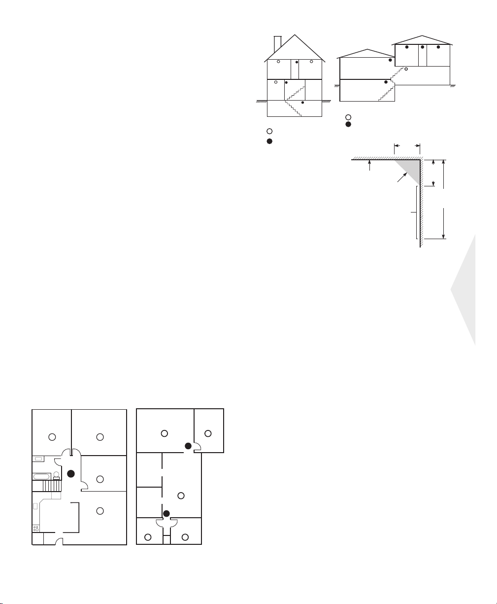
Directives pour la localisation des détecteurs de fumée
L’expérience démontre que les incendies dans les résidences génèrent de la fumée en plus ou moins grande
quantité. Des tests conduits avec des incendies typiques
dans des résidences indiquent que, dans la plupart des
cas, des quantités détectables de fumée précèdent les
hausses de température. Pour ces raisons, les détecteurs
de fumée doivent être installés à l’extérieur des chambres
à coucher et sur chaque étage de la résidence.
L’information qui suit n’est qu’à titre indicatif. Lorsque vient le temps de localiser et d’installer des avertisseurs
d’incendie, il est recommandé de consulter la règlementation ainsi que le code des incendies local.
Il est recommandé d’installer un plus grand nombre
d’avertisseurs d’incendie que ce qui est requis pour une
protection minimale. Les endroits tels que le sous-sol, les
chambres à coucher (particulièrement celles des
fumeurs), la salle à dîner, la chaufferie, les pièces utilitaires, ainsi que les couloirs devraient également être
protégés.
Sur les plafonds dégagés, les détecteurs peuvent être espacés de 9.1m (30 pieds). Un espace différent peut être
requis selon la hauteur du plafond, la circulation d’air, la
présence de poutrelles, l’absence d’isolant, etc. Pour des
recommandations sur l’installation, consultez le National
Fire Alarm Code NFPA 72, CAN/ULS-S553-M86 ou tout
autre norme nationale.
N’installez pas les détecteurs de fumée sur des plafonds
pointus ou à pignon; l’espace d’air immobile dans ces emplacements peut empêcher l’unité de détecter la fumée.
Évitez les endroits avec des courants d’air turbulents,
comme par exemple près des portes, des ventilateurs et
des fenêtres. Les mouvements d’air rapides autour de
l’unité peuvent empêcher la fumée de pénétrer à l’intérieur du détecteur.
Salle
de séjour
Chambre
à coucher
Chambre à
coucher
Chambre à
coucher
Chambre à
coucher
Salle à
manger
Cuisine
Salle de
jeux
Chambre à
Salle de
Chambre à
coucher
séjour
Sous-sol
Avertisseurs de fumée pour
une meilleure protection
Avertisseurs de fumée pour
une protection minimum
coucher
Figure 3
Salle à
manger
Chambre à
Salle de
séjour
Sous-sol
Avertisseurs de fumée pour une meilleure protection
Avertisseurs de fumée pour une protection minimum
Figure 3A
Plafond
Emplacement
acceptable
Jamais dans
cette zone
Le détecteur peut
être installé
à l’intérieur de cette
Note: La circonférence
du détecteur ne doit
pas dépasser les
limites indiquées.
zone
Chambre à
coucher
Maison à deux niveaux
4 po.
0,1 m
Optionnel
Salle de jeux
coucher
Corridor
4 po.
0,1 m
min.
Mur de
côté
12 po.
0,3 m
max.
Figure 4
N’installez pas les détecteurs où l’humidité est élevée.
N’installez pas les détecteurs dans des endroits où la tem-
pérature s’élève au-dessus de 38oC (100oF) ou descend
plus bas que 5oC (41oF).
Les détecteurs de fumée doivent toujours être installés
conformément au National Fire Alarm Code NFPA72. Les
détecteurs de fumée doivent toujours être placés conformément aux :
“Des détecteurs de fumée devraient être installés à l’extérieur et près des chambres à coucher et à chaque étage
de la résidence, incluant le sous-sol et excluant les vides
sanitaires et les greniers non finis. Dans les constructions
neuves, un détecteur de fumée devrait également être installé dans chaque chambre à coucher.”
“Dispositions pour les résidences à demi-niveaux. L’installation de détecteurs de fumée est requise aux endroits indiqués dans le schéma. Les détecteurs de fumée
sont optionnels lorsqu’il n’y a pas de porte entre le salon
et la salle de jeu.”
Français
Cuisine
Figure 1
Salle de
séjour
Chambre
à coucher
Chambre
à coucher
Figure 2
25
Page 28

Incendie domestique vérification de la sécurité
Lisez cette section attentivement pour des renseignements importants relatifs à la sécurité incendie.
La majorité des incendies se produisent dans les foyers. Pour minimiser ce danger, nous recommandons de mener
une vérification de la sécurité incendie domestique et d'élaborer un plan d'évacuation.
1. Est-ce que tous les appareils et prises électriques sont en bonne condition ? Vérifiez qu'il n'y a pas de cordon
effiloché, que les circuits électriques ne sont pas surchargés, etc. Si vous avez de la difficulté à évaluer l'état de vos
appareils électriques et électroménagers, faites appel à un professionnel.
2. Est-ce que tous les liquides inflammables sont rangés dans des contenants hermétiques à un endroit sûr, frais et
bien aéré ? Tout nettoyage à l'aide de liquides inflammables doit être évité.
3. Est-ce que les objets présentant des risques d'incendie (allumettes), sont rangés hors de portée des enfants ?
4. Est-ce que les chaudières et appareils de combustion au bois sont correctement installés, propre et en bon état de
fonctionnement ? Demandez à un professionnel d'évaluer ces appareils.
Plan d'évacuation en cas d'incendie
En général il y a très peu de temps entre le moment où l'incendie est détecté et le moment où il devient mortel. C'est
pourquoi il est très important d'établir un plan d'évacuation de la famille et de faire des exercices.
1. Chaque membre de la famille devrait participer à l'élaboration du plan d'évacuation.
2. Examinez toutes les voies possibles d'évacuation à partir de chaque endroit de la maison. Puisque de nombreux
incendies se produisent la nuit, une attention particulière doit être portée aux voies d'évacuation à partir des chambres à coucher.
3. L'évacuation d'une chambre à coucher doit être possible sans avoir à en ouvrir la porte.
Tenez compte des éléments suivants lorsque vous établissez votre plan d'évacuation.
• Assurez-vous que toutes les portes et fenêtres sont faciles à ouvrir. Assurez-vous qu'elles ne sont pas bloquées par de la
peinture et que leur mécanisme de verrouillage fonctionne correctement.
• Si l'ouverture des sorties ou leur accès pose des problèmes à des enfants, à des personnes âgées ou handicapées, des
plans d'évacuation, prévoyez un plan de secours. Cela signifie s'assurer que ceux qui doivent assurer le secours réagir
promptement au signal d'alarme incendie.
• Si la sortie est au-dessus du rez-de-chaussée, prévoyez une échelle ou une corde d'incendie et apprenez à l'utiliser.
• Toutes les sorties du rez-de-chaussée doivent être dégagées. En hiver, n'oubliez pas de nettoyer la neige, de ranger les
meubles et équipement de jardin qui pourraient bloquer les portes-fenêtres et empêcher une sortie rapide.
• Chaque famille doit convenir d'un point de rencontre où on pourra s'assurer que personne ne manque à l'appel, par
ex., de l'autre côté de la rue ou chez un voisin. Une fois que tout le monde est sorti de la maison, appelez les pompiers
• Un bon plan privilégie la rapidité d'évacuation. Ne cherchez pas les causes de l'incendie et ne tentez pas de le combattre ou de sauver des biens et des animaux domestiques car vous perdriez alors un temps précieux. Une fois à
l'extérieur, ne rentrez pas dans la maison. Attendez les pompiers.
• Rédigez votre plan d'évacuation et faites des exercices fréquemment de sorte que, en cas d'urgence, tout le monde
sache ce qu'il faut faire. Révisez le plan lorsque les conditions changent, par exemple, le nombre de personnes vivant à
la maison ou s'il y a des modifications architecturales.
• Assurez-vous que votre système de détection d'incendie fonctionne bien en faisant des essais hebdomadaires (voir
‘Essai de système (clavier, sirène et batterie)” on page 23.). Si vous ne savez pas comment votre système fonctionne,
contactez votre installateur.
• Nous vous recommandons de contacter votre service des incendies le plus proche et de demander des renseignements sur la sécurité incendie et l'élaboration d'un plan d'évacuation. Si vous le pouvez, demandez à un inspecteur de
la prévention des incendies de venir faire une inspection de votre domicile.
26
Page 29

GARANTIE LIMITÉE
La société Digital Security Controls Ltée. garantit le produit contre toutes défectu-
osités matérielles et d’assemblage dans des conditions normales d’utilisation, à
l’acheteur original, pendant une période de douze mois à partir de la date d’achat.
Dans l’application de cette garantie, la société Digital Security Controls Ltée.
s’engage, à son choix, à réparer ou à remplacer tout matériel défectueux dès son
retour à un dépôt de réparation, sans frais de main d’oeuvre et matériels. Tout remplacement et/ou réparation sont garantis pendant le reste de la durée de la garantie
originale ou quatre vingt dix (90) jours, ou l’une ou l’autre est la plus longue. Le
propriétaire original doit avertir la société Digital Security Controls Ltée. par courrier que le matériel ou l’assemblage sont défectueux ; dans tous les cas, cette notification doit être reçue avant l’expiration de la période de garantie. Il n'y a absolument
aucune garantie sur les logiciels et tous les logiciels sont vendus comme utilisateur
de licence dans le cadre du contrat licence d'utilisation du produit. Le client assume
toute la responsabilité de la sélection, de l'installation et de l'entretien de tout produit
acheté auprès de DSC. Les produits personnalisés ne sont garantis que dans la
mesure où ils ne fonctionnent pas à la livraison. Dans ce cas, DSC peut, à son choix,
remplacer le produit ou créditer le client.
■
Garantie Internationale
La garantie pour les clients internationaux est la même que pour tous les clients au
Canada et aux Etats-Unis, sauf que la société Digital Security Controls Ltée. ne
sera pas responsable des frais de douanes, taxes, ou TVA qui pourraient être dus.
■
Procédure pour la Garantie
Pour obtenir un service sous garantie, veuillez retourner les produit(s) en question
au point d’achat. Tous les distributeurs autorisés et vendeurs ont un programme de
garantie. Quiconque retourne des marchandises à la société Digital Security Controls Ltée. doit tout d’abord obtenir un numéro d’autorisation. La société Digital
Security Controls Ltée. n’acceptera aucun envoi pour lequel une autorisation
préalable n’aura pas été obtenue.
■
Conditions d’annulation de la Garantie
Cette garantie ne s’applique qu’aux vices de matériels et d’assemblage liés à une
utilisation normale. Elle ne couvre pas:
• dommage encouru lors de l’expédition ou la manutention ;
• dommage causé par un désastre tel qu’un incendie, inondation, vent, tremble-
ment de terre ou foudre ;
• dommage dû à des causes hors du contrôle de la société Digital Security Controls Ltée. tel que voltage excessif, choc mécanique ou dommage des eaux ;
• dommage causé par attachement non autorisé, changements, modifications ou
objets étrangers ;
• dommage causé par périphériques (à moins que les périphériques ne soient fournis par la société Digital Security Controls Ltée.) ;
• défauts causés par l’impossibilité de fournir un environnement d’installation
adapté aux produits ;
• dommage causé par l’utilisation des produits pour des usages autres que ceux
pour lesquels ils ont été conçus ;
• dommage pour mauvais entretien ;
• dommage provenant de tout autre mauvais traitement, mauvaise manutention ou
mauvaise utilisation des produits.
Ce qui n'est pas couverts par la garantie
■
En plus des éléments qui annulent la garantie, la garantie ne couvrira pas : i) les
frais de transport au centre de réparation ; ii) les produits qui ne sont pas identifiés
avec l'étiquette de produit de DSC et un numéro de lot ou un numéro de série ; iii)
les produits démontés ou réparés de manière qui affecte la performance ou qui
empêche une inspection ou un essai afin de vérifier toute réclamation au titre de la
garantie. Les cartes ou les insignes d'accès renvoyés pour être remplacés au titre
de la garantie seront remplacés ou crédités au choix de DSC. Les produits qui ne
sont pas couverts par cette garantie ou qui ne sont plus garantis parce qu'ils sont
trop vieux, qu'ils ont été mal utilisés ou endommagés, seront examinés et une estimation de réparation sera fournie. Aucune réparation ne sera effectuée avant la
réception d'un bon de commande valable envoyé par le client et d'un numéro
d'autorisation de renvoi de marchandise (RMA) envoyé par le service à la clientèle de DSC.
S’il y a un problème de réparation du produit après un nombre raisonnable de tentatives au titre de la présente garantie, les obligations contractuelles de la société
Digital Security Controls Ltée. seront limitées au remplacement du produit,
comme seule réparation de l’inobservation de la garantie. En aucun cas la Société
Digital Security Controls Ltée. ne sera responsable des dommages particuliers,
accidentels ou indirects basés sur l’inobservation de la garantie, une rupture de
contrat, une négligence, une responsabilité stricte ou sur toute autre théorie
juridique. De tels dommages incluent, mais ne sont limités à, une perte de profit,
une perte de produit ou tout autre équipement associé, au coût de capital, au coût
de remplacement de l’équipement, à l’aménagement ou services, à l’indisponibil-
ité, au temps de rachat, aux réclamations des tiers, notamment les clients, aux
dommages et intérêts à la propriété, etc. Dans certaines juridictions, la loi limite
ou ne permet pas une exonération de garantie en cas d'endommagement indirect.
Si les lois d'une telle juridiction s'appliquent à une réclamation par ou contre DSC,
les limites et les exonérations contenues dans la présente garantie respecteront la
loi. Certains États ne permettent pas l'exonération ou la limite de dommages accidentels ou indirects, la déclaration ci-dessus pourrait donc ne pas s'appliquer à
votre cas.
■
Stipulation d’exonération de garanties
Cette garantie contient l’entière garantie et remplace toutes les autres garanties,
qu’elles soient explicites ou implicites (notamment toutes les garanties implicites de
marchandise ou aptitude pour un usage particulier) et de toutes autres obligations ou
responsabilités de Digital Security Controls Ltée. Digital Security Controls Ltée.
n’assume et n’autorise aucune autre personne prétendant agir en son nom de modifier ou changer cette garantie, n’assume pour cela aucune autre garantie ou responsabilité concernant ce produit.
Cette stipulation d’exonération de garanties et garantie restreinte sont gouvernées
par les lois de la province de l’Ontario, Canada.
ATTENTION: Digital Security Controls Ltée. recommande que la totalité du
système soit testé régulièrement. Toutefois, même si vous faites des essais péri-
odiques, il peut arriver que le fonctionnement du produit ne soit pas conforme aux
spécifications en raison notamment, mais pas exclusivement, d’interventions
criminelles ou de panne de courant.
■
Verrouillage de l’Installateur
Tous produits renvoyés à DSC qui ont une option verrouillage de l’Installateur
activée et ne montrent pas d’autres problèmes seront sujets à des frais d’entretien.
■
Réparations en dehors de la Garantie
Digital Security Controls Ltée. réparera à son choix ou remplacera en dehors de la
garantie les produits renvoyés à son usine dans les conditions suivantes.
Quiconque retourne des produits à Digital Security Controls Ltée. doit d’abord
obtenir un numéro d’autorisation. Digital Security Controls Ltée. n’acceptera
aucun envoi quel qu’il soit, pour lequel une autorisation préalable n’aura pas été
obtenue.
Les produits que Digital Security Controls Ltée. juge être réparables seront
réparés et renvoyés. Les frais prédéterminés par Digital Security Controls Ltée., et
sujets à un rajustement périodique, seront facturés pour chaque unité réparée.
Les produits que Digital Security Controls Ltée. juge ne pas être réparables seront
remplacés par le produit équivalent le plus proche disponible à ce moment. Le
prix du marché en cours du produit de remplacement sera facturé pour chaque
unité de remplacement.
27
Page 30

ADVERTENCIA
Por favor lea cuidadosamente
Nota para los Instaladores
Esta advertencia contiene información vital. Para el único individuo en contacto
con el sistema del usuario, es su responsabilidad tratar a cada artículo en esta
advertencia para la atención a los usuarios de este sistema.
Fallas del Sistema
El sistema ha sido cuidadosamente diseñado para ser tan efectivo como sea
posible. Hay circunstancias, sin embargo, incluyendo incendio, robo u otro tipo de
emergencias donde no podrá proveer protección. Cualquier sistema de alarma o
cualquier tipo puede ser comprometido deliberadamente o puede fallar al operar
como se espera por una cantidad de razones. Algunas pero no todas pueden ser:
Instalación Inadecuada
Un sistema de seguridad debe ser instalado correctamente en orden para proporcionar una adecuada protección. Cada instalación debe ser evaluada por un profesional de seguridad, para asegurar que todos los puntos y las áreas de acceso están
cubiertas. Cerraduras y enganches en ventanas y puertas deben estar seguras y
operar como está diseñado. Ventanas, puertas, paredes, cielo rasos y otros materiales del local deben poseer suficiente fuerza y construcción para proporcionar el
nivel de protección esperado. Una reevaluación se debe realizar durante y después
de cualquier actividad de construcción. Una evaluación por el departamento de
policía o bomberos es muy recomendable si este servicio está disponible.
Conocimiento Criminal
Este sistema contiene características de seguridad las cuales fueron conocidas para
ser efectivas en el momento de la fabricación. Es posible que personas con intenci-
ones criminales desarrollen técnicas las cuales reducen la efectividad de estas características. Es muy importante que el sistema de seguridad se revise
periódicamente, para asegurar que sus características permanezcan efectivas y que
sean actualizadas o reemplazadas si se ha encontrado que no proporcionan la protección esperada.
Acceso por Intrusos
Los intrusos pueden entrar a través de un punto de acceso no protegido, burlar un
dispositivo de sensor, evadir detección moviéndose a través de un área de
cubrimiento insuficiente, desconectar un dispositivo de advertencia, o interferir o
evitar la operación correcta del sistema.
Falla de Energía
Las unidades de control, los detectores de intrusión, detectores de humo y muchos
otros dispositivos de seguridad requieren un suministro de energía adecuada para
una correcta operación. Si un dispositivo opera por baterías, es posible que las baterías fallen. Aún si las baterías no han fallado, estas deben ser cargadas, en buena
condición e instaladas correctamente. Si un dispositivo opera por corriente CA,
cualquier interrupción, aún lenta, hará que el dispositivo no funcione mientras no
tiene energía. Las interrupciones de energía de cualquier duración son a menudo
acompañadas por fluctuaciones en el voltaje lo cual puede dañar equipos electrónicos tales como sistemas de seguridad. Después de que ocurre una interrupción de
energía, inmediatamente conduzca una prueba completa del sistema para asegurarse que el sistema esté funcionando como es debido.
Falla en Baterías Reemplazables
Los transmisores inalámbricos de este sistema han sido diseñados para proporcionar años de duración de la batería bajo condiciones normales. La esperada vida de
duración de la batería, es una función de el ambiente, el uso y el tipo del disposi-
tivo. Las condiciones ambientales tales como la exagerada humedad, altas o bajas
temperaturas, o cantidades de oscilaciones de temperaturas pueden reducir la
duración de la batería. Mientras que cada dispositivo de transmisión tenga un mon-
itor de batería bajo el cual identifica cuando la batería necesita ser reemplazada,
este monitor puede fallar al operar como es debido. Pruebas y mantenimiento regulares mantendrán el sistema en buenas condiciones de funcionamiento.
Compromiso de los Dispositivos de Frecuencia de Radio
(Inalámbricos)
Las señales no podrán alcanzar el receptor bajo todas las circunstancias las cuales
incluyen objetos metálicos colocados en o cerca del camino del radio o interferencia deliberada y otra interferencia de señal de radio inadvertida.
Usuarios del Sistema
Un usuario no podrá operar un interruptor de pánico o emergencias posiblemente
debido a una inhabilidad física permanente o temporal, incapaz de alcanzar el dispositivo a tiempo, o no está familiarizado con la correcta operación. Es muy importante que todos los usuarios del sistema sean entrenados en la correcta operación
del sistema de alarma y que ellos sepan como responder cuando el sistema indica
una alarma.
Detectores de Humo
Los detectores de humo, que son una parte del sistema, pueden no alertar correctamente a los ocupantes de un incendio por un número de razones, algunas son las
siguientes. Los detectores de humo pueden haber sido instalados o ubicados incor-
rectamente. El humo no puede ser capaz de alcanzar los detectores de humo, como
cuando el fuego es en la chimenea, paredes o techos, o en el otro lado de las puertas
cerradas. Los detectores de humo no pueden detectar humo de incendios en otros
niveles de la residencia o edificio.
Cada incendio es diferente en la cantidad de humo producida y la velocidad del
incendio. Los detectores de humo no pueden detectar igualmente bien todos los
tipos de incendio. Los detectores de humo no pueden proporcionar una advertencia
rápidamente de incendios causados por descuido o falta de seguridad como el
fumar en cama, explosiones violentas, escape de gas, el incorrecto almacenamiento
de materiales de combustión, circuitos eléctricos sobrecargados, el juego con fósforos por parte de los niños o un incendio provocado.
Aún si el detector de humo funciona como está diseñado, pueden haber circunstancias donde hay insuficiente tiempo de advertencia para permitir a los ocupantes
escapar a tiempo para evitar heridas o muerte.
Detectores de Movimiento
Los detectores de movimiento solamente pueden detectar movimiento dentro de
las áreas designadas como se muestra en las respectivas instrucciones de instalación. Los detectores de movimiento no pueden discriminar entre intrusos y los
que habitan el local o residencia. Los detectores de movimiento no proporcionan
un área de protección volumétrica. Estos poseen múltiples rayos de detección y el
movimiento solamente puede ser detectado en áreas no obstruidas que están cubiertas por estos rayos. Ellos no pueden detectar movimiento que ocurre detrás de las
paredes, cielo rasos, pisos, puertas cerradas, separaciones de vidrio, puertas o ventanas de vidrio. Cualquier clase de sabotaje ya sea intencional o sin intención tales
como encubrimiento, pintando o regando cualquier tipo de material en los lentes,
espejos, ventanas o cualquier otra parte del sistema de detección perjudicará su
correcta operación.
Los detectores de movimiento pasivos infrarrojos operan detectando cambios en la
temperatura. Sin embargo su efectividad puede ser reducida cuando la temperatura
del ambiente aumenta o disminuye de la temperatura del cuerpo o si hay orígenes
intencionales o sin intención de calor en o cerca del área de detección. Algunos de
los orígenes de calor pueden ser calentadores, radiadores, estufas, asadores, chimeneas, luz solar, ventiladores de vapor, alumbrado y así sucesivamente.
Dispositivos de Advertencia
Los dispositivos de advertencia, tales como sirenas, campanas, bocina, o estroboscópicos no podrán alertar o despertar a alguien durmiendo si hay una puerta o
pared intermedio. Si los dispositivos de advertencia están localizados en un nivel
diferente de la residencia o premisas, por lo tanto es menos posible que los ocupantes puedan ser advertidos o despertados. Los dispositivos de advertencia audible pueden ser interferidos por otros orígenes de ruidos como equipos de sonido,
radios, televisión, acondicionadores de aire u otros electrodomésticos., o el tráfico.
Los dispositivos de advertencia audible, inclusive de ruido fuerte, pueden no ser
escuchados por personas con problemas del oído.
Líneas Telefónicas
Si las líneas telefónicas son usadas para transmitir alarmas, ellas puedan estar fuera
de servicio u ocupadas por cierto tiempo. También un intruso puede cortar la línea
o sabotear su operación por medios más sofisticados lo cual sería de muy difícil la
detección.
Tiempo Insuficiente
Pueden existir circunstancias cuando el sistema funcione como está diseñado, y
aún los ocupantes no serán protegidos de emergencias debido a su inhabilidad de
responder a las advertencias en cuestión de tiempo. Si el sistema es supervisado, la
respuesta puede no ocurrir a tiempo para proteger a los ocupantes o sus pertenencias.
Falla de un Componente
A pesar que todos los esfuerzos que se han realizado para hacer que el sistema sea
lo más confiable, el sistema puede fallar en su función como se ha diseñado debido
a la falla de un componente.
Prueba Incorrecta
La mayoría de los problemas que evitan que un sistema de alarma falle en operar
como es debido puede ser encontrada por medio de pruebas y mantenimiento regular. Todo el sistema debe ser probado semanalmente e inmediatamente después de
una intrusión, un intento de intrusión, incendio, tormenta, terremoto, accidente o
cualquier clase de actividad de construcción dentro o fuera de la premisa. La
prueba debe incluir todos los dispositivos de sensor, teclados, consolas, dispositivos para indicar alarmas y otros dispositivos operacionales que sean parte del
sistema.
Seguridad y Seguro
A pesar de sus capacidades, un sistema de alarma no es un sustituto de un seguro
de propiedad o vida. Un sistema de alarma tampoco es un substituto para los
dueños de la propiedad, inquilinos, u otros ocupantes para actuar prudentemente a
prevenir o minimizar los efectos dañinos de una situación de emergencia.
28
Page 31

Tabla de contenido
Teclados Numericos ............................................................................................................................. 30
Hoja de referencia ............................................................................................................................... 33
Su Sistema de Seguridad..................................................................................................................... 35
Armado (activación/establecimiento) ............................................................................................... 36
Desarme (desactivación/anulación del establecimiento) ................................................................. 36
Armado presente (parcialmente activado/parcialmente establecido) ............................................ 36
Teclas de emergencia .......................................................................................................................... 36
Si la alarma se activa .......................................................................................................................... 36
Alarma de intrusión (robo) Sirena continua .....................................................................................36
Alarma de incendio (Sirena discontinua) .......................................................................................... 37
Memoria de alarma ............................................................................................................................. 37
Restablecimiento de sensores ............................................................................................................ 37
Comprobación del sistema (teclado numérico, sirena y batería) ....................................................37
Programación de códigos de acceso .................................................................................................. 37
Programación de la hora y fecha ....................................................................................................... 38
Salida rápida ........................................................................................................................................ 38
Timbre de puerta (pitidos de entrada/salida) ...................................................................................38
Condiciones de problema ................................................................................................................... 38
Exclusión ..............................................................................................................................................38
Lineamientos para la ubicación de detectores de humo ..................................................................39
Revisión de la protección doméstica contra incendios .....................................................................40
Para obtener soporte técnico:
Información de la estación central de supervisión:
Nº de cuenta:_____________________ Tel# : _______________________
Información del instalador:
Compañía: _______________________ Tel# : ________________________
Si sospecha que se ha enviado una señal de falsa alarma a la estación central de supervisión, póngase en contacto
con ésta para evitar una respuesta innecesaria.
29
Page 32

Teclados Numericos de PowerSeries
PC5532Z
Indicadores
de estado
de zona
Indicadores
de estado
Botones
de funcion
[
PC1555RKZ
Indicadores
de funcion
PC5508Z
PC5516Z
Teclas de
emergencia
Su instalador pudo haber instalado uno
de estos teclados de LED en caso de que
Ud. posea 16 zonas o menos en su sistema. Estos teclados tienen el mismo funcionamiento que un teclado PC5532.
[
Indicadores
de estado
Base
numerica
Indicadores
de estado
de zona
Teclas de
emergencia
30
Page 33

Indicadores
de estado
Base
numerica
Botones de
funcion
Sirena
LCD5501Z
F1
F2
F3
F4
F5
LCD5500Z
Quedar
Ausnt
Timbre
Ajuste
Salir
Teclados Numericos d’Envoy
NT9005-433
Pantallas
Teclas de
desplazamiento
Teclas de
emergencia
Pantallas
Indicadores
de estado
Teclas de
emergencia
Base
numerica
[
[
[
Botones
de función
Español
31
Page 34
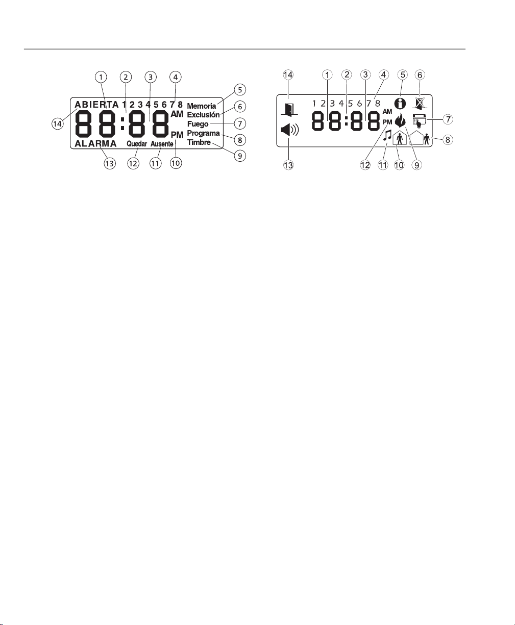
LCD
Mensaje escrito
1 Dígitos 1 y 2 del reloj– Estos dos dígitos de 7 segmentos del reloj indican los dígitos de la hora cuando el reloj
local está activo, e identifica la zona cuando el símbolo ABIERTA o ALARMA están activos. Estos dos dígitos muestran una zona por segundo desde el número de zona más bajo al más alto al ir mostrando las zonas
2 : (dos puntos) – Este símbolo es el divisor de las horas/minutos y destellará una vez por segundo cuando el reloj
local esté activo.
3 Dígitos del Reloj 3 y 4 – Estos dos dígitos del reloj son los dígitos de los minutos cuando el reloj local está activo.
4 1 al 8 – Estos símbolos identifican Fallas cuando es presionado [✱][2].
5 Memoria – Indica que hay alarmas en la memoria.
6 Exclusión – Indica que hay zonas que han sido excluídas en forma automática o manual.
7
Programa
– Indica que el sistema está en Programación del Instalador, o que el teclado está ocupado.
ICON
8 Ausente – Indica que el panel está armado en el modo Ausente. Este se encenderá al comienzo de la demora de
salida.
9 Fuego – Indica que hay alarmas de incendio en la memoria.
10 Quedar – Indica que el panel está armado en el modo Presente. Este se encenderá al comienzo de la demora de salida.
11
Timbre – Este símbolo se enciende cuando se presiona [✱][4] o
sistema. Presione [✱][4] o
12 AM, PM – Este símbolo indica que el reloj local está mostrando la hora en formato de 12 Hs. Estos íconos no
estarán encendidos si el sistema está programado para formato de 24 Hs.
13 ALARMA– Este símbolo es usado con los dígitos 1 y 2 del reloj para indicar zonas en alarma en el sistema. Cuando
una zona está en alarma, el símbolo ALARMA se encenderá, y los displays de 7 segmentos 1 y 2 mostrarán las zonas
en alarma.
14 ABIERTA – Este símbolo es usado con los dígitos 1 y 2 del reloj para indicar zonas violentadas (no en alarma) en el
sistema. Cuando las zonas son abiertas, el símbolo ABIERTA se encenderá, y los dígitos 1 y 2 del reloj mostrarán
las distintas zonas violentadas.
Timbre para deshabilitar la Timbre de Puerta.
32
Timbre para habilitar la Timbre de Puerta en el
Page 35

Hojas de referencia
.
Complete la siguiente información para futuras consultas y guarde este manual en un lugar seguro.
Códigos de acceso
Código maestro [40] : _______________________
Código
01 09 17 25
02 10 18 26
03 11 19 27
04 12 20 28
05 13 21 29
06 14 22 30
07 15 23 31
08 16 24 32
C
ódigo de acceso
Código
Código de acceso
Código
Código de acceso
Información del sensor (de la zona)
¿Habilitado?
❏ [F] FUEGO ❏ [A] AUXILIO ❏ [P] PÁNICO
Tiempo de demora de salida: ____ segundos.
Tiempo de demora de entrada: ____ segundos
Código
Código de acceso
Español
33
Page 36

Sensor Area Protegida Tipo de Sensor Sensor Area Protegida Tipo de Sensor
01 33
02 34
03 35
04 36
05 37
06 38
07 39
08 40
09 41
10 42
11 43
12 44
13 45
14 46
15 47
16 48
17 49
18 50
19 51
20 52
21 53
22 54
23 55
24 56
25 57
26 58
27 59
28 60
29 61
30 62
31 63
32 64
34
Page 37

Con Relación a su Sistema de Seguridad
Su equipo de seguridad DSC ha sido diseñado para brindarle la mayor flexibilidad y comodidad. Lea este manual cuidadosamente
y solicite a su instalador que lo oriente en el manejo del sistema y las características implantadas en él. Todos los usuarios de este
sistema deben ser igualmente instruidos en el uso del mismo. Complete la página de “Información del Sistema” con toda la información de las zonas y códigos de acceso y guárdela en un lugar seguro para una futura referencia.
Detección de Fuego
Este equipo es capaz de monitorear dispositivos de detección de fuego, como detectores de humo, además provee una advertencia si detecta una condición de fuego. La eficaz detección de fuego, depende del número adecuado de detectores de humo,
localizados en lugares apropiados. Este equipo debe ser instalado de acuerdo con la norma de NFPA 72 (N.F.P.A. Batterymarch
Park, Quincey MA 02269). Estudie cuidadosamente las guías de planes de escape familiar en este manual.
NOTA: Su instalador debe habilitar la sección de detección de fuego de este equipo antes de su funcionamiento.
Probar
Para asegurar que su sistema continúe funcionando como está diseñado, usted debe probar su sistema semanalmente. Por favor
consulte “Comprobacion del Sistema”. Si su sistema no funciona adecuadamente, llame a su compañía instaladora para servicio.
Monitoreo
Este sistema es capaz de transmitir: alarmas, fallas e información de emergencia a una estación de monitoreo por medio de una
línea telefónica. Si usted, inadvertidamente inicia una alarma, llame inmediatamente a la estación de monitoreo para evitar una
reacción innecesaria.
NOTA: La función de monitoreo debe ser habilitada por el instalador antes de su funcionamiento.
Operación General del Sistema
Su sistema de seguridad ha sido compuesto por un control DSC, uno o más teclados y varios sensores y detectores. El control debe
ser instalado fuera de la vista en un cuarto de utilería o el sótano. La caja metálica contiene los accesorios electrónicos del sistema,
fusibles y batería de reserva. Generalmente no hay razón para que alguien diferente al instalador o a la persona encargada del
mantenimiento tengan acceso al control.
Todos los teclados tienen un indicador audible y teclas de entrada de comandos. Los teclados LED tienen un grupo de zonas y
indicadores del estado del sistema. Los teclados LCD tienen una pantalla de cristal liquido alfanumérica (LCD).
El teclado es usado para enviar comandos al sistema y para mostrar el estado actual del sistema. El (los) teclado (s) será (n) montado
(s) en un lugar conveniente dentro del local cerca a la (s) puerta (s) de entrada/salida.
El sistema de seguridad posee varias zonas de protección de área y cada una de esas zonas debe ser conectada a uno o más sensores (detectores de movimiento, de rompimiento de vidrios, contactos de puerta, etc). Un sensor en alarma será indicado por los
indicadores de Zonas 1 - 6 destellando en un teclado LED o por un mensaje escrito en el teclado LCD.
Importante
Un sistema de seguridad no puede prevenir emergencias. Su propósito es la de alertar al cliente en caso de una emergencia y - si
se ha incluido - su estación de monitoreo. Los sistemas de seguridad son generalmente confiables, pero estos quizás no trabajen
bajo ciertas condiciones, además, no substituyen otros métodos de seguridad como tampoco constituye seguros de vida y/o propiedad. Su sistema de seguridad debe ser instalado y se le debe dar mantenimiento por parte de profesionales calificados en sistemas de seguridad quienes deben instruirlo en el nivel de protección que ha sido suministrado y en la operación de su sistema.
35
Español
Page 38

Armado (activación/establecimiento)
Cierre todos los sensores (anule el movimiento y cierre las ventanas). El indicador luminoso Listo ( ) se encenderá.
Para armar el sistema, presione y mantenga pulsada la tecla Ausnt durante 2 segundos o inserte el código de acceso.
El indicador luminoso Armado ( ) se encenderá y el teclado numérico pitará.
Dispone ahora de ____ segundos para abandonar las instalaciones que pretende proteger. Para cancelar la secuencia de
armado, inserte el código de acceso.
Error en el armado
Se emitirá un tono de error si el sistema no se puede armar. Esta circunstancia tendrá lugar si el sistema no está preparado
para armarse (los sensores están abiertos) o si se ha insertado un código de usuario incorrecto. Si esto ocurre, asegúrese
de que todos los sensores están seguros, presione y inténtelo de nuevo.
Desarme (desactivación/anulación del establecimiento)
Inserte el código de acceso para desarmar en cualquier momento el sistema armado (el indicador Armado está encendido).
El teclado numérico pitará si cruza la puerta de entrada. Debe insertar el código de acceso antes de que transcurran ___
segundos para evitar una condición de alarma.
Error en el desarme
Si el código no es válido, el sistema no se desarmará y se emitirá un tono de error durante 2 segundos. Si se produce esta
situación, inténtelo de nuevo.
Armado presente (parcialmente activado/parcialmente establecido)
El armado presente excluirá la protección interior (los sensores de movimiento) y armará el perímetro del sistema (puertas
y ventanas). Cierre todos los sensores (anule el movimiento y cierre las ventanas). El indicador luminoso Listo se encenderá.
Consulte a su compañía de seguridad si esta función está disponible en el sistema.
Presione y mantenga pulsada la tecla Quedar durante 2 segundos o inserte el código de acceso y no salga del local.
El indicador Armado y el indicador Excluir o Sistema se encenderán. El sistema excluirá automáticamente ciertos sensores
interiores (sensores de movimiento).
Teclas de emergencia
Las teclas de emergencia Fuego, Auxilio y Pánico NO funcionarán si el instalador no las ha programado y activado.
Presione la tecla
a su compañía de seguridad si las teclas de emergencia están disponibles en el sistema.
F, A o P por 2 segundos para generar una alarma de incendio, auxilio o pánico, respectivamente. Consulte
Si la alarma se activa
El sistema puede generar 2 sonidos de alarma diferentes:
Sirena continua = Alarma de intrusión (robo)
Sirena discontinua = Alarma de incendio
Alarma de intrusión (robo) Sirena continua
¡Si no está seguro de la causa de la alarma, aproxímese con cuidado!
Si la alarma se activó accidentalmente, inserte el código de acceso para desactivarla. Póngase en contacto con la estación
central de supervisión para evitar un dispacho.
36
Page 39
Alarma de incendio (Sirena discontinua)
¡Siga su plan de evacuación de emergencia inmediatamente!
Si la alarma de incendio se activó accidentalmente (por ejemplo, a causa de una tostadora eléctrica o del vapor del cuarto
de baño, etc.), inserte el código de acceso para desactivarla. Póngase en contacto con la estación central de supervisión
para evitar un dispacho.Consulte a su compañía de seguridad si el sistema se ha equipado con detección de incendios.
Para restablecer los detectores, consulte la sección Restablecimiento de sensores.
Memoria de alarma
Cuando una alarma se activa, el indicador luminoso Memoria o Sistema (y el indicador Fuego, si es aplicable) se encenderán.
Para ver los sensores que generaron la alarma, presione . El indicador luminoso Memoria o Sistema y el número
de sensor correspondiente destellarán (por ejemplo el sensor 3).
Para el teclado numérico LCD5500, use las teclas de desplazamiento para ver los sensores de la memoria de alarma
Presione para salir. Para borrar la memoria, arme y desarme el sistema.
Si se activa una alarma mientras el sistema está armado, el teclado numérico pasará inmediatamente a la memoria de
alarma cuando desarme el sistema. En este caso, debe aproximarse con cuidado, ya que el intruso aún puede estar dentro del local o del edificio.
Restablecimiento de sensores
Ciertos sensores, después de haber detectado una condición de alarma, requieren un restablecimiento para que abandonen dicha condición (por ejemplo los sensores de rotura de vidrio, los detectores de humo, etc.). Consulte a su compañía de seguridad si es necesario realizar esta función en el sistema. Para restablecer los detectores, presione y
mantenga pulsada la tecla Ajuste por dos segundos o presione .
Si un sensor no se puede restablecer, es posible que siga detectando una condición de alarma. Si se restablece, la alarma
se cancela. Si no se restablece, la alarma se reactivará o continuará sonando.
Comprobación del sistema (teclado numérico, sirena y batería)
Informe a la estación de supervisión cuando usted comienza a probar su sistema, así como, cuando la prueba
se a terminado.
Presione más el código de acceso maestro. El indicador Programa o Sistema destellará y el indicador Armado se
encenderá.
Presione para iniciar la prueba de 2 segundos (la sirena y el teclado numérico se activarán). Presione para salir.
Programación de códigos de acceso
Además del código de acceso maestro, puede programar hasta 32 códigos de acceso de usuario adicionales. Presione
más el código de acceso maestro. El indicador Programa o Sistema comenzará a destellar y el indicador Armado
se encenderá.
Inserte el número de 2 dígitos que desee programar (por ejemplo, 06 para el código de acceso de usuario 6; inserte 40
para el código de acceso maestro). El indicador Listo se encenderá.
Con el LCD5500, utilice las teclas de desplazamiento para buscar el código específico y presione para selec-
cionarlo.
Inserte el nuevo código de acceso de 4 dígitos o presione para borrarlo. Cuando haya completado la programación,
inserte otro código de 2 dígitos que desee programar o presione para salir.
Para sistemas que utilicen múltiples particiones y áreas, se pueden asignar códigos de acceso a varias de ellas o a parti-
ciones o áreas específicas. Póngase en contacto con su compañía de seguridad para obtener más detalles.
37
Español
Page 40

Programación de la hora y fecha
Presione más el código de acceso maestro. El indicador luminoso Programa o Sistema comenzará a destellar y el
indicador luminoso Armado se encenderá.
Presione para seleccionar la hora y la fecha. El indicador luminoso Listo se encenderá.
Con el LCD5500, use las teclas de des plazamiento para buscar la opción de menú que desea y presione para
seleccionarla.
Inserte la hora en el formato de 24 horas (HH:MM) y, a continuación, la fecha (MM:DD:AA). Presione para salir de la
programación.
Salida rápida
Si el sistema está armado y necesita salir, utilice la función Salida rápida para no tener que desarmar y volver a armar el
sistema. Presione y mantenga pulsada la tecla Salir durante 2 segundos o presione .
A partir de ese momento dispondrá de 2 minutos para abandonar el local por la puerta de salida. Cuando la puerta se
cierre de nuevo, el tiempo de salida restante se cancelará.
Timbre de puerta (pitidos de entrada/salida)
Para activar o desactivar la función del timbre de la puerta, presione y mantenga pulsada la tecla Timbre durante dos
segundos o presione .
Condiciones de problema
Cuando se detecta una condición de problema, el indicador luminoso Falla o Sistema se enciende y el teclado numérico
pita cada 10 segundos. Presione la tecla para silenciar los pitidos. Presione para ver la condición del problema.
El indicador Falla o Problema destellará.
Condición de problema Comentarios Acción
1
Se requiere servicio Solicitar servicio
2
Pérdida de alimentación de CASi ha habido un apagón en el edificio y/o alrededores, el sistema
3
Fallo de la línea telefónica El sistema ha detectado que la línea telefónica está cortada. Solicitar servicio
4
Fallo de comunicación El sistema intentó comunicarse con la estación central de supervisión, pero
5
Fallo de sensor (o zona) El sistema está teniendo problemas con uno o varios sensores del sistema. Solicitar servicio
6
Sabotaje de sensor (o zona) El sistema ha detectado una condición de sabotaje en uno o varios
7
Batería baja del sensor (o de
la zona)
8
Pérdida de hora y fecha Si la alimentación falló por completo (CA y batería), será necesario volver a
continuará funcionando con la batería durante unas horas.
no lo consiguió. Esta circunstancia puede deberse al problema 3.
sensores del sistema.
Si el sistema se ha equipado con sensores inalámbricos, uno o varios de
ellos ha informado de una condición de batería baja.
programar la fecha y la hora.
Solicitar servicio
Solicitar servicio
Solicitar servicio
Solicitar servicio
Solicitar servicio
Exclusión
Para excluir un sensor, presione . El indicador luminoso Excluir o Sistema destellará.
Inserte el número de 2 dígitos para excluir el sensor (por ejemplo 03 para el sensor número 3). Para excluir otro sensor,
inserte el número de 2 dígitos correspondiente a dicho sensor.
Con el LCD5500, utilice las teclas de desplazamiento para buscar el sensor específico y presione para excluirlo.
Presione para salir. El indicador luminoso Excluir o Sistema se encenderá.
38
Page 41
Lineamientos para la ubicación de detectores de humo
Las investigaciones han mostrado que los incendios hostiles en los hogares generan humo en mayor o menor
proporción. Los experimentos con incendios típicos en
hogares indican que cantidades detectables de humo
preceden a niveles detectables de calor en la mayoría de
los casos. Por este motivo, las alarmas de humo deberían
estar instaladas fuera de cada área de descanso y en cada
planta de la vivienda.
La siguiente información es una guía general solamente y
se recomienda consultar los códigos y regulaciones locales al ubicar e instalar alarmas de humo.
Se recomienda instalar alarmas de humo adicionales
además de las requeridas para la protección mínima. Las
áreas adicionales que deberían estar protegidas incluye: el
sótano; dormitorios, especialmente donde duermen fumadores; comedores; sitios con hornos o de salas de trabajo y
todos los corredores que no estén protegidos por las unidades requeridas.
En los cielorasos, los detectores pueden espaciarse a 9.1m
(30 pie) cada uno, como guía. Otras distancias pueden ser
requeridas dependiendo de la altura del cieloraso, corrientes de aire, la presencia de viguetas, cieloraso sin aislación, etc. Consulte el Código Nacional de Alarma de
Incendio NFPA 72, CAN/ULC-S553-M86 u otras normas
nacionales apropiadas en recomendaciones de instalación.
No ubique detectores de humo en la parte superior de
cielorasos cerrados o tejados; la no circulación de aire en
estos lugares produce que la unidad no detecte el humo.
Evite áreas con mucha corriente de aire, tales como cercanas a puertas, ventiladores o ventanas. El movimiento
de aire rápido alrededor del detector puede impedir que
el humo ingrese a la unidad.
Dormitorio Dormitorio
Dormitorio
Cocina
Sala
Figura 1
Salón familiar
Comedor
Cocina
Dormitorio
Dormitorio
Sala
Dormitorio
Figura 2
DormitorioDormitorio
Sala
Sótano
Figura 3
Alarmas de Humo para
una protección mínima
Alarmas de Humo para
una mejor protección
Cielo raso
NOTA: Las medidas mostradas
están en el borde de más
cercano a el detector
Comedor
Posición
aceptable
Sala
Sótano
Alarmas de Humo para
una protección mínima
4 pulgadas
(0.1m)
NUNCA
AQUI
Parte alta del
detector se
acepta aqui
Pared
Figura 4
Figura 3A
4pulgadas
(0.1m)
máxima
12 pulgadas
Cuarto de Esparcimiento
Arreglo de Dos Niveles
(0.3m)
máxima
DormitorioDormitorio
Vestíbulo
Opcional
Alarmas de Humo para
una mejor protección
No ubique detectores en áreas con niveles de humedad
alto.
No coloque detectores en áreas donde la temperatura sobrepasa los 38oC (100oF) o por debajo de los 5oC (41oF).
Los detectores de humo deberían ser instalados siempre
de acuerdo con el Código Nacional de Alarma de Incendio NFPA 72,. Los detectores de humo deberían estar ubicados siempre de acuerdo con:
NFPA 72,: ‘Los detectores de humo deben ser instalados
fuera de cada área de descanso en un lugar continuo inmediato de los dormitorios y en cada planta adicional de
la unidad habitacional, incluyendo sótano y excluyendo
espacios reducidos y áticos sin finalizar. En una construcción nueva, el detector de humo debe ser instalado en
cada área de descanso’.
NFPA 72,: ’Disposición para dos niveles. Los detectores de
humo son necesarios en las ubicaciones que se muestran.
Los detectores de humo son opcionales donde no existe
una puerta entre la sala de estar y la sala de recreación’.
Español
39
Page 42

Revisión de la protección doméstica contra incendios
Lea esta sección atentamente. Contiene importante sobre protección contra incendios.
La mayoría de los incendios se producen en el hogar. Para minimizar este riesgo, se recomienda realizar una revisión
de la protección doméstica contra incendios y confeccionar un plan de evacuación de incendios.
1. ¿Se encuentran todos los electrodomésticos y todas las tomas de corriente en buen estado? Compruebe que no haya
cables pelados, circuitos eléctricos sobrecargados, etc. Si no está seguro del estado en el que se encuentran los electrodomésticos o los servicios domésticos, póngase en contacto con un profesional para que analice estos aparatos.
2. ¿Están todos los líquidos inflamables almacenados en contenedores cerrados en un lugar fresco y perfectamente ventilado? Debe evitar la limpieza con líquidos inflamables.
3. ¿Se encuentran los materiales con riesgo de incendio (fósforos) fuera del alcance de los niños?
4. ¿Están las calderas y equipos de calefacción propiamente instalados, limpios y en buen estado de funcionamiento?
Póngase en contacto con un profesional para que analice estas instalaciones.
Plan de evacuación contra incendios
Con frecuencia, no transcurre mucho tiempo entre la detección de un incendio y su mortal propagación. Por tanto,
es muy importante que se haya confeccionado y puesto en práctica un plan de evacuación familiar.
1. Cada miembro de la familia debe participar en la confección del plan de evacuación.
2. Investigue las posibles rutas de evacuación desde cada una de las ubicaciones de la casa. Dado que muchos incendios tienen lugar durante la noche, preste especial atención a las rutas de evacuación desde los dormitorios.
3. Se debe poder realizar la evacuación desde un dormitorio sin necesidad de abrir la puerta interior.
Tenga en cuenta los puntos siguientes cuando confeccione los planes de emergencia:
• Asegúrese de que todas las puertas y ventanas exteriores se abren fácilmente. Asegúrese de que no están pegadas por la pintura y que sus mecanismos de cierre y apertura funcionan correctamente.
• Si la apertura o utilización de la salida es demasiado dificultosa para los niños, ancianos o minusválidos, se deben
confeccionar planes de rescate. Para ello es necesario garantizar que aquellas personas que realizan el rescate
pueden oír inmediatamente la señal de aviso de incendio.
• Si la salida se encuentra por encima del nivel del suelo, se debe proporcionar una escalera o cuerda que cumpla la
normativa de incendios, así como un curso de formación para su utilización.
• Las salidas que se encuentren al nivel del suelo deben permanecer despejadas. En invierno, asegúrese de retirar la
nieve de las puertas exteriores; de igual forma, el mobiliario o equipamiento exterior no debe bloquear las salidas.
• Todo el mundo debe conocer el punto de encuentro predeterminado donde se puedan reunir (por ejemplo, al
otro lado de la calle o en la casa de un vecino). Cuando todo el mundo haya abandonado el edificio, póngase en
contacto con el cuerpo de bomberos.
• Un plan eficaz favorece una evacuación rápida. No realice indagaciones sobre el incendio ni intente sofocarlo, ni
se detenga para llevarse pertenencias ni mascotas, ya que perderá un tiempo vital. Una vez fuera de la casa, no
vuelva a entrar. Espere a que lleguen los bomberos.
• Anote el plan de evacuación contra incendios y póngalo en práctica frecuentemente de forma que si se produce
una situación de emergencia, todo el mundo sepa lo que hacer. Revise el plan cuando las condiciones cambien,
como el número de personas en el hogar, o si se producen modificaciones en la construcción del edificio.
• Asegúrese de que el sistema de aviso de incendio funciona realizando pruebas semanales (consulte el apartado
“Comprobación del sistema (teclado numérico, sirena y batería)” on page 37). Si no está seguro de que el sistema
funciona perfectamente, póngase en contacto con el instalador.
• Es recomendable ponerse en contacto con los bomberos locales y solicitar más información sobre protección y
planes de evacuación contra incendios. Si estuviera disponible, proponga al personal encargado de la prevención
de incendios que realice una inspección de protección contra incendios en la casa.
40
Page 43

GARANTÍA LIMITADA
Digital Security Controls Ltd. garantiza al comprador original que por un periodo de
doce meses desde la fecha de compra, el producto está libre de defectos en materiales y
hechura en uso normal. Durante el periodo de la garantía, Digital Security Controls
Ltd., decide sí o no, reparará o reemplazará cualquier producto defectuoso devolviendo
el producto a su fábrica, sin costo por labor y materiales. Cualquier repuesto o pieza
reparada está garantizada por: el resto de la garantía original o noventa (90) días, cualquiera de las dos opciones de mayor tiempo. El propietario original debe notificar puntualmente a Digital Security Controls Ltd. por escrito que hay un defecto en material o
hechura, tal aviso escrito debe ser recibido en todo evento antes de la expiración del
periodo de la garantía. No hay absolutamente ningún tipo de garantía sobre software y
todos los productos de software son vendidos como una licencia de usuario bajo los
términos del contrato de licencia del software incluido con el producto. El comprador
asume toda responsabilidad por la apropiada selección, instalación, operación y mantenimiento de cualquier producto comprado a DSC. La garantía de los productos hechos
a medida alcanzan solamente a aquellos productos que no funcionen al momento de la
entrega. En tales casos, DSC puede reemplazarlos o acreditarlos, a opción de DSC.
■
Garantía Internacional
La garantía para los clientes internacionales es la misma que para cualquier cliente de
Canadá y los Estados Unidos, con la excepción que Digital Security Controls Ltd. no
será responsable por cualquier costo aduanero, impuestos o VAT que puedan ser apli-
cados.
Procedimiento de la Garantía
Para obtener el servicio con esta garantía, por favor devuelva el(los) artículo(s) en
cuestión, al punto de compra. Todos los distribuidores autorizados tienen un programa de garantía. Cualquiera que devuelva los artículos a Digital Security Controls
Ltd., debe primero obtener un número de autorización. Digital Security Controls Ltd.,
no aceptará ningún cargamento de devolución sin que haya obtenido primero el
número de autorización.
■
Condiciones para Cancelar la Garantía
Esta garantía se aplica solamente a defectos en partes y en hechura concerniente al
uso normal. Esta no cubre:
• daños incurridos en el manejo de envío o cargamento
• daños causados por desastres tales como incendio, inundación, vientos, terremotos
o rayos eléctricos.
• daños debido a causas más allá del control de Digital Security Controls Ltd., tales
como excesivo voltaje, choque mecánico o daño por agua.
• daños causados por acoplamientos no autorizados, alteraciones, modificaciones u
objetos extraños.
• daños causados por periféricos (al menos que los periféricos fueron suministrados
por Digital Security Controls Ltd.);
• defectos causados por falla en al suministro un ambiente apropiado para la instalación de los productos;
• daños causados por el uso de productos, para propósitos diferentes, para los cuales
fueron designados;
• daño por mantenimiento no apropiado;
• daño ocasionado por otros abusos, mal manejo o una aplicación no apropiada de los
productos.
■
Items no cubiertos por la Garantía
Además de los ítems que cancelan la Garantía, los siguientes ítems no serán cubiertos
por la Garantía: (i) costo de flete hasta el centro de reparación; (ii) los productos que
no sean identificados con la etiqueta de producto de DSC y su número de lote o
número de serie; (iii) los productos que hayan sido desensamblados o reparados de
manera tal que afecten adversamente el funcionamiento o no permitan la adecuada
inspección o pruebas para verificar cualquier reclamo de garantía. Las tarjetas o eti-
quetas de acceso devueltas para su reemplazo bajo la garantía, serán acreditadas o
reemplazadas a opción de DSC. Los productos no cubiertos por la presente garantía, o
de otra manera fuera de la garantía debido al transcurso del tiempo, mal uso o daño,
serán evaluados y se proveerá una estimación para la reparación. No se realizará
ningún trabajo de reparación hasta que una orden de compra válida enviada por el
Cliente sea recibida y un número de Autorización de Mercadería Devuelta (RMA) sea
emitido por el Servicio al Cliente de DSC.
La responsabilidad de Digital Security Controls Ltd., en la falla para reparar el producto bajo esta garantía después de un número razonable de intentos será limitada a
un reemplazo del producto, como el remedio exclusivo para el rompimiento de la
garantía. Bajo ninguna circunstancias Digital Security Controls Ltd., debe ser responsable por cualquier daño especial, incidental o consiguiente basado en el rompimiento
de la garantía, rompimiento de contrato, negligencia, responsabilidad estricta o cualquier otra teoría legal. Tales daños deben incluir, pero no ser limitados a, perdida de
ganancias, perdida de productos o cualquier equipo asociado, costo de capital, costo
de substitutos o reemplazo de equipo, facilidades o servicios, tiempo de inactividad,
tiempo del comprador, los reclamos de terceras partes, incluyendo clientes, y perjuicio a la propiedad. Las leyes de algunas jurisdicciones limitan o no permiten la
renuncia de daños consecuentes. Si las leyes de dicha jurisdicción son aplicables
sobre cualquier reclamo por o en contra de DSC, las limitaciones y renuncias aquí
contenidas serán las de mayor alcance permitidas por la ley. Algunos estados no permiten la exclusión o limitación de daños incidentales o consecuentes, en tal caso lo
arriba mencionado puede no ser aplicable a Ud.
■
Renuncia de Garantías
Esta garantía contiene la garantía total y debe prevalecer sobre cualquiera otra garantía
y todas las otras garantías, ya sea expresada o implicada (incluyendo todas las garantías
implicadas en la mercancía o fijada para un propósito en particular) Y todas las otras
obligaciones o responsabilidades por parte de Digital Security Controls Ltd. Digital
Security Controls Ltd., no asume o autoriza a cualquier otra persona para que actué en
su representación, para modificar o cambiar esta garantía, ni para asumir cualquier otra
garantía o responsabilidad concerniente a este producto.
Esta renuncia de garantía y garantía limitada son regidas por el gobierno y las leyes
de la provincia de Ontario, Canadá.
ADVERTENCIA: Digital Security Controls Ltd., recomienda que todo el sistema
sea completamente probado en forma regular. Sin embargo, a pesar de las pruebas
frecuentes, y debido a, pero no limitado a, sabotaje criminal o interrupción eléctrica,
es posible que este producto falle en trabajar como es esperado.
■
Cierre del Instalador
Cualquier producto regresado a DSC con la opción de Cierre del Instalador habilitada
y ninguna otra falla aparente estará sujeto a cargos por servicio.
■
Reparaciones Fuera de la Garantía
Digital Security Controls Ltd., en su opción reemplazará o reparará los productos por
fuera de la garantía que sean devueltos a su fábrica de acuerdo a las siguientes condiciones. Cualquiera que esté regresando los productos a Digital Security Controls Ltd.,
debe primero obtener un número de autorización. Digital Security Controls Ltd., no
aceptará ningún cargamento sin un número de autorización primero.
Los productos que Digital Security Controls Ltd., determine que son reparables serán
reparados y regresados. Un cargo fijo que Digital Security Controls Ltd., ha predeterminado y el cual será revisado de tiempo en tiempo, se exige por cada unidad reparada.
Los productos que Digital Security Controls Ltd., determine que no son reparables
serán reemplazados por el producto más equivalente disponible en ese momento. El
precio actual en el mercado del producto de reemplazo se cobrará por cada unidad
que se reemplace.
41
Page 44

FCC COMPLIANCE STATEMENT
CAUTION: Changes or modifications not expressly approved by Digital Security
Controls Ltd. could void your authority to use this equipment.
This equipment has been tested and found to comply with the limits for a Class B digital
device, pursuant to Part 15 of the FCC Rules. These limits are designed to provide reasonable protection against harmful interfer-ence in a residential installation. This equipment generates, uses and can radiate radio frequency energy and, if not installed and used
in accordance with the instructions, may cause harmful interference to radio communications. However, there is no guarantee that interference will not occur in a particular installation. If this equipment does cause harmful interference to radio or television
reception, which can be deter-mined by turning the equipment off and on, the user is encouraged to try to correct the interference by one or more of the following measures:
• Re-orient the receiving antenna.
• Increase the separation between the equipment and receiver.
• Connect the equipment into an outlet on a circuit different from that to which the
receiver is connected.
• Consult the dealer or an experienced radio/television technician for help.
The user may find the following booklet prepared by the FCC useful: "How to Identify and
Resolve Radio/Television Interference Problems". This booklet is available from the U.S.
Government Printing Office, Washington D.C. 20402, Stock # 004-000-00345-4.
The keypads represented in this manual can be used with the following Control Units:
PC580, PC1555MX, PC5010, PC5015, PC5020 or the NT9005.
IMPORTANT INFORMATION
This equipment complies with Part 68 of the FCC Rules and, if the product was approved July 23, 2001 or later, the requirements adopted by the ACTA. On the side of
this equipment is a label that contains, among other information, a product identifier. If
requested, this number must be provided to the Telephone Company.
PC580 Product identifier: US: F53AL01BPC580
PC1555MX Product identifier US:F53AL01BPC1555
PC5010 FCC Registration# F53CAN-22839-AL-E; REN=0.1B
PC5015 FCC Registration# F53CAN-32104-AL-E; REN=0.6B
PC5020 FCC Registration# F53CAN-34330-AL-E; REN=0.1B
NT9005 FCC Registration# F53CAN-36358-AL-E; REN=0.1B
USOC Jack: RJ-31X
Telephone Connection Requirements
A plug and jack used to connect this equipment to the premises wiring and telephone
network must comply with the applicable FCC Part 68 rules and requirements adopted
by the ACTA. A compliant telephone cord and modular plug is provided with this product. It is designed to be connected to a compatible modular jack that is also compliant.
See installation instructions for details.
Ringer Equivalence Number (REN)
The REN is used to determine the number of devices that may be connected to a telephone line. Excessive RENs on a telephone line may result in the devices not ringing in
response to an incoming call. In most but not all areas, the sum of RENs should not exceed five (5.0). To be certain of the number of devices that may be connected to a line,
as determined by the total RENs, contact the local Telephone Company. For products
approved after July 23, 2001, the REN for this product is part of the product identifier
that has the format US: AAAEQ##TXXXX. The digits represented by ## are the REN
without a decimal point (e.g., 03 is a REN of 0.3). For earlier products, the REN is separately shown on the label.
Incidence of Harm
If this equipment (PC580, PC1555MX, PC5010, PC5015, PC5020 or the NT9005)
causes harm to the telephone network, the telephone company will notify you in advance that temporary discontinuance of service may be required. But if advance notice
is not practical, the Telephone Company will notify the customer as soon as possible.
Also, you will be advised of your right to file a complaint with the FCC if you believe
it is necessary.
Changes in Telephone Company Equipment or Facilities
The Telephone Company may make changes in its facilities, equipment, operations or
procedures that could affect the operation of the equipment. If this happens the Telephone Company will provide advance notice in order for you to make necessary modifications to maintain uninterrupted service.
Equipment Maintenance Facility
If trouble is experienced with this equipment (PC580, PC1555MX, PC5010, PC5020
and the NT9005), for repair or warranty information, please contact the facility indicated below. If the equipment is causing harm to the telephone network, the Telephone
Company may request that you disconnect the equipment until the problem is solved.
This equipment is of a type that is not intended to be repaired by the end user.
Simplex Time Recorder Co. 100 Simplex Drive, Westminster MA 01441-0001 USA,
Tel: (978) 731-2500
Additional Information
Connection to party line service is subject to state tariffs. Contact the state public utility
commission, public service commission or corporation commission for information.
Alarm dialing equipment must be able to seize the telephone line and place a call in an
emergency situation. It must be able to do this even if other equipment (telephone, answering system, computer modem, etc.) already has the telephone line in use. To do so,
alarm dialing equipment must be connected to a properly installed RJ-31X jack that is
electrically in series with and ahead of all other equipment attached to the same telephone line. Proper installation is depicted in the figure below. If you have any questions
concerning these instructions, you should consult your telephone company or a qualified installer about installing the RJ-31X jack and alarm dialing equipment for you.
Customer Premises Equipment and Wiring
Network
Service
Provider's
Facilities
Telephone
Line
Network
Demarcation
Point
RJ-31X
Telephone
Jack
Alarm Dialing
Answering
System
Equipment
Unused
RJ-11 Jack
Fax Machine
Telephone
Computer
Unused
RJ-11 Jack
Telephone
©2003 Digital Security Controls Ltd.
Toronto, Canada •
www.dsc.com
Printed in Canada Imprimé au Canada Impreso en Canadá
 Loading...