

DSC Power832/X-10 PRO Special Application Manual

Power832/X-10 PRO
Residential Project Kit
For Lighting Control
Special Application Guide

Table of Contents
Power832/X-10 PRO Residential Project Kit ........................................................................... 1
Installation ................................................................................................................................ 2
Home Automation Operation .................................................................................................. 4
Application 1: Basic Lighting Control ...................................................................................... 5
Application 2: Courtesy Lighting ............................................................................................. 7
Application 3: Alarm Signal Lighting ...................................................................................... 9
Application 4: Fire Escape Route Lighting ............................................................................ 10
Application 5: Simulated Home Occupancy .......................................................................... 11
Additional Features of the Escort5580 .................................................................................. 12
Power832/X-10 PRO Residential
Project Kit
Introduction The Power832/X-10 PRO Residential Kit for Lighting Control provides exciting opportuni-
ties for you to attract new customers and boost sales. Here are just a few of the ways automated lighting control can make your customer feel even more safe and secure.
• Your customer can turn lights on and off from any touch-tone phone.
• You can provide a light that automatically comes on during exit/entry periods.
• You can provide a light that signals an alarm.
• You can provide a lighted fire escape route.
• You can simulate home occupancy to discourage intruders.
In this guide, we show you how easy it is to plan and program each of these applications
for your customers.
It is recommended that you read this entire manual
before
starting
the system installation.
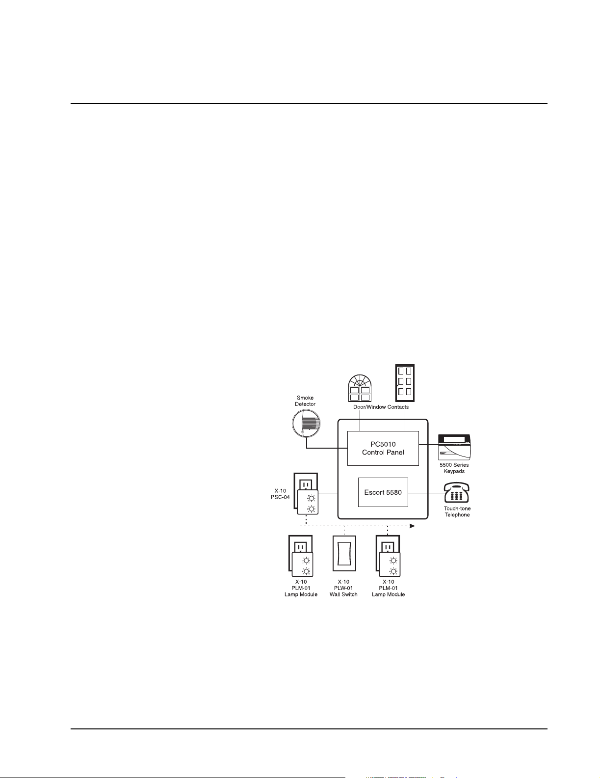
The Control Panel houses the Escort5580 Module which controls lights and other electrical
devices using the Automation Modules from X-10 Corporation. One X-10 module is
required for each device (Automation Item) you want to control. One X-10 Power-line Interface is required for the system to connect to the house wiring. The 6 foot cord included
connects the Escort module to the PSC-04 X-10 Power-line Interface.
About This Manual This manual is intended to guide you through the process of installing and programming
the security and home automation system. It first deals with the actual installation of the
devices and later with the operation and the programming of the Automation items. Please
note that the Security portion of your kit will be installed according to the
tion Manual
, included
PC5010 Installa-
1
Installation
STEP 1 Installing the Security Alarm System
For additional information, see:
Install and program the security alarm system (Power832 Control and all detecting
devices) as normal.
Once you are satisfied that the security system is working properly, you can begin the
installation of the Escort5580 Module and the home automation devices.
Before proceeding further, disconnect both AC and DC power from the Power832 Control.
The panel utilizes EEPROM memory and will retain all programming.
PC5010 Installation Manual
STEP 2 Installing The Escort5580 Module
For additional information, see:
Install the Escort5580 Module, which will consist of mounting the module inside the same
cabinet as the main control or in a separate enclosure located close to the control panel.
Use the nylon stand-offs provided.
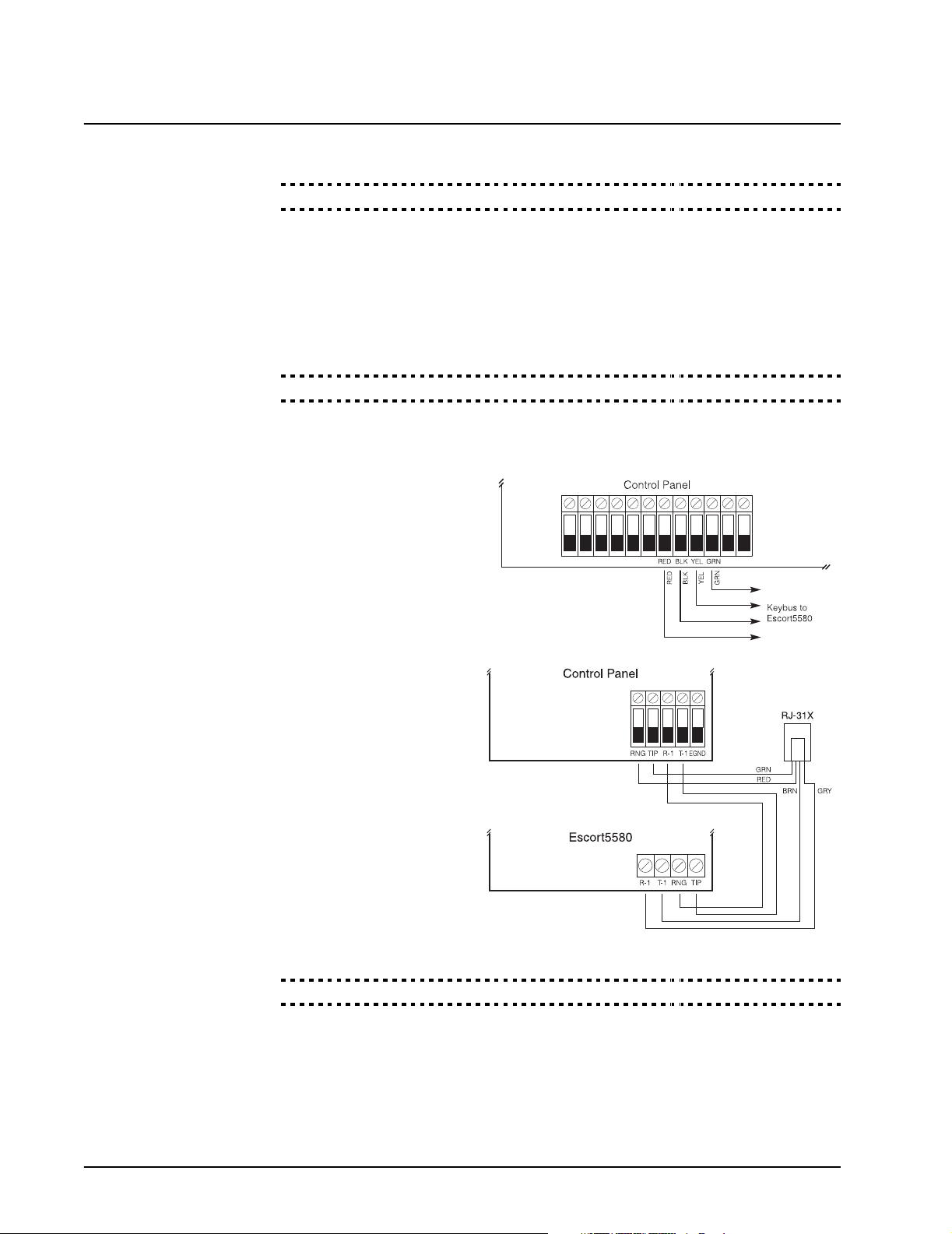
Connect the Keybus wiring as
shown in the following diagram:
Escort5580 Installation Manual
, Sections 2.1, 2.2, and 2.3
Connect the incoming phone
line to TIP and RING of the
control panel. Connect T1
and R1 of the control panel to
TIP and RING of the
Escort5580. Connect the
return to the house phones to
T1 and R1 of the Escort5580.
Reconnect both AC and DC
power to the Power832 Control Panel.
STEP 3 Enrolling the Escort5580 Module
For additional information, see:
The Escort5580 module will automatically function properly as soon as STEP 2 is completed and will be ‘enrolled’ on the system within one minute after power is applied.
NOTE: Once enrol led, the Escort module is fully supe rvised b y the Power832 control pane l
which will generate a Supervisory Trouble if the module is removed from the system.
Escort5580 Installation Manual
, Section 2.4
2

To confirm the Escort5580 module is connected properly to the control panel, perform the
following:
1. Press [*] [8] [Installer Code] - enter Installer Programming
2. Press [903] - enter Module Supervision Section If you are using an LED Keypad, Light #24 should be on. This means the module is con-
nected properly and in communication with the panel via the Keybus. If you are using an
LCD Keypad, scroll through the display. The keypad will show each module enrolled on
the system. It will read ’Escort5580’ if the enrollment has been successful.
If the enrollment has been unsuccessful, remove power, check all wiring between the control panel and the Escort5580. Once any wiring problems have been resolved, reconnect
power, repeat this STEP 3, or see
Escort5580 Installation Manual
, Section 2.4
STEP 4 Connecting the X-10 Power-line Interface (Model PSC-04)
Plug one end of the 6’ connector cord into the jack on the Escort5580 and the other end
into the X-10 PSC-04 Power-line Interface. Plug the X-10 PSC-04 Power-line Interface unit
into an unswitched, 110 Volt outlet.
STEP 5 Installing the X-10 Control Modules
The two X-10 Lamp (Control) Modules supplied with this kit plug into a 110 Volt outlet near
the lights that you wish to control. The Escort5580 can control any incandescent light
plugged into a Lamp Module.
NOTE:
Lights plugged into the X-10 Control Modules will also operate normally by turning the individual light switch on and off. The l igh t fixture switch must be left i n the ‘on’ position in order
for the control functions to operate.
Other types of X-10 Control Modules are available from your local distrib utor. These include
Wall Switch and Appliance modules.
Each X-10 Lamp Module must have a unique ID or code
for independent operation. The ID number has two components:
• a letter from A to P (‘House Code’)
• a number from 1 to 16 (‘Unit Number’).
Using a screwdriver, set any ID (House Code & Unit
Number) you want by turning the two dials on the front of
the module.
In Appendix B of the
Installation
find the House
A U T O M A T I O N I T E M H O U S E C O D E S & U N I T N U M B E R S
Enter Code
[000] A 1
[001] A 2
[002] A 3
[003] A 4
Enter Code
[052] D 5
[053] D 6
[054] D 7
[055] D 8
Appendix B
Enter Code
[103] G 8
[104] G 9
[105] G 10
[106] G 11
Enter Code
[154] J 11
[155] J 12
[156] J 13
[157] J 14
Programming Code
(House & Unit Number)
(From Appendix B)
Automation Device
Escort5580
Manual,
Code and Unit Number
that you have selected for
each module. Write down
the three digit number
found to the left of the code (use the space below). This is the number that you will use
when programming the Escort5580.
Record Module Information Here:
Module Location Code
Enter Code
[205] M 14
[206] M 15
[207] M 16
[208] N 1
Module # 1
Module # 2
3
 Loading...