

DSC PK5590CL User Manual
PK5590CL Touch Screen
Security Interface
Compatible with PowerSeries Control Panels
User Guide
IMPORTANT
This manual contains information on the limitations
regarding product use and function and information
on the limitations as to liability of the manufacturer.
Read the entire manual carefully.

INDEX..............................Page QUICK REFERENCE
Access Codes .....................13
Arming
....... Away .............................8
....... Stay...............................7
Brightness...........................11
Bypassing Zones ..................9
Chime....................................9
Clean Mode.........................11
Contrast ..............................11
Disarming........................... 7,8
Emergency Buttons...............2
Functions ............................10
Language............................10
LED Indicators ......................2
Logs ...................................... 9
Silence Beeps.....................11
Zones, bypassing.................. 9
Status Indicators ...................2
Time/Date ...........................12
Troubles (see logs)................9
Welcome screen ................... 4
Welcome > Main Menu >Settings > More > Access Codes
Welcome > Main Menu > Arm Away
Welcome > Main Menu > Arm Stay
Welcome > Main Menu > Settings > More > [Brightness]
Welcome > Main Menu > Bypass
Welcome > Main Menu > Settings > More > [Chime]
Welcome > Main Menu > Settings > [Start] (Cleaning Mode)
Welcome > Main Menu > Settings > More > [Contrast]
If not visible tap screen
Welcome > Main Menu > Functions > [Function 1/2/3/4]
Welcome > Main Menu > Settings > [English]/[French]
Welcome > Main Menu > Logs
Welcome > Main Menu > Settings > More > [Silence Beeps]
Welcome > Main Menu > Bypass
Welcome > Main Menu > Settings > More > Time/Date
Welcome > Main Menu > Logs
Disarm System to view Welcome screen

1. Introduction
The PK5590CL Touch Screen is an interactive touch-sensitive color LCD that can be used on Partition 1 of any PowerSeries
control panel. Due to the custom requirements of individual installations some of the features described here may perform differently than described. Refer to your installer’s instructions for the details of your specific installation and to the User manual
for general security system information.
Specifications/Features
Display...........................................................................................................1/4 VGA (320x240 pixel) Color Touch Screen
Emergency Buttons ........................................................................................................................ 3 (Fire, Auxiliary, Panic)
LED Indicators............................................................................................................................ 3 (Ready, Armed, Trouble)
Dimensions (mounting) ....................................................................................................................................5-3/8”x3-7/8”
Wiring Distance ...................................................................................................................600ft (4-wire, 18 AWG Keybus)
NOTE: Programming changes may take up to 5 minutes to take effect. During this period the touch screen ignores user
input and displays “System Unavailable” in the Status Bar.
1
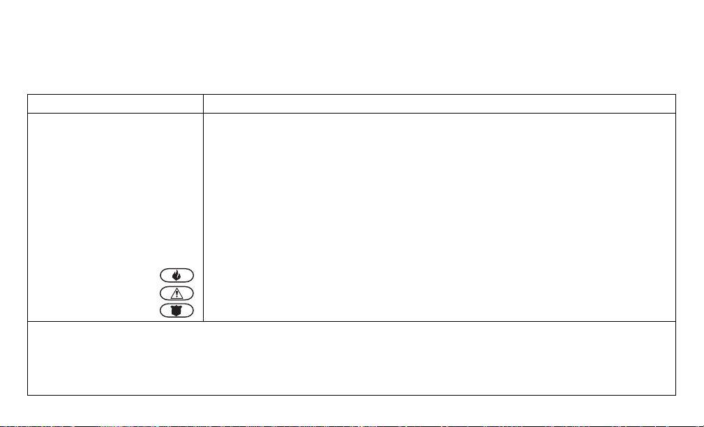
Controls & Indicators
The following table lists the Led Indicator and push button functions. Most operations are performed by tapping an
area indicated on the screen displayed.
Function Description
LED Indicators:
Ready Light (GREEN)
Armed Light (RED)
Trouble Light (YELLOW))
Emergency Keys:
IMPORTANT NOTE: The Auxiliary and Panic Keys are ON by default. The Fire Key will not function unless programmed by the
Installer. If the keypad is programmed "Silent" the keypad will not change when a key is pressed. These events are recorded in the
LOG.
ON indicates the system is ready for arming.
The system cannot be armed unless the Ready light is ON.
ON indicates the system has been successfully Stay Armed or Away Armed.
FLASHING indicates the system has been successfully armed with no entry delay.
ON indicates there is trouble on the system.
Press the Logs menu from the Main menu to view troubles.
Fire Assistance Required. Press and hold for 2 seconds to activate
Medical or other Assistance Required. Press and hold for 2 seconds to activate
Police Assistance Required. Press and hold for 2 seconds to activate
2
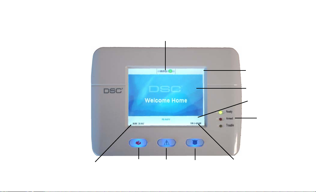
Figure 1, Controls & Indicators
Context Sensitive Help
Title Bar
Work Area
Time
LED Status
Indicators
Date
Fire Auxiliary Panic
EMERGENCY BUTTONS
Status Bar
3

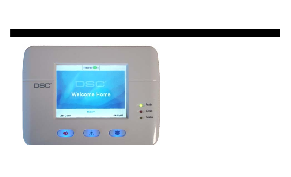
LCD Touch Screen
Welcome screen
The Touch Screen LCD is 1/4 VGA 320 x 240 pixel display
This screen will blank after 15 minutes of inactivity. Tapping the screen will restore the display.
During normal operation (unarmed) and system star tup the WELCOME screen is displayed.
From here a series of screens can be accessed that allow the user to perform Arming/disarming and other User functions. To navigate through the various screens, refer to Quick Access
guide at the front of this document and to Figure 2, Touch Screen Flowchart
Indoor and Outdoor Temperature is displayed in the top left and right corners of the screen if
an Escort module and temperature sensors have been installed.
The INFO button provides context sensitive help for the current screen
Date & Time are displayed in the lower left and right corners of the screen
System Status (i.e., Ready, Armed, Exit Delay etc. is displayed in the bottom center of the
screen.
NOTE: Tapping Date or Time will display the Date/Time Programming screen
Tapping the screen anywhere between the upper and lower status bars will display the Main
Menu screen
4
 Loading...