


Installation Instructions, Instructions d’Installation , Instrucciones de instalación, Instruções de instalação
123
456
78
0
*
#
9
RFK5500
PK5500
123
456
78
0
*
#
9
RFK5501
PK5501
123
456
78
0
*
#
9
RFK5508
PK5508
123
456
78
0
*
#
9
RFK5516
PK5516
29007789R001
PK55XX/RFK55XX v1.2
English, Français, Español, Português
WARN ING:
NOTE:
ATTENTION:
NOTE:
ATENCIÓN:
NOTA:
AVI SO :
NOTA:
Please refer to the System Installation Manual for information on limitations regarding pro duct use and function and information on the limitations as to liability of the manufacturer.
These instructions shall be used in conjunction with the system Installation Manual of the Control Panel with which this equipment is intended to be used.
Ce manuel contient des informations sur les restrictions concernant le fonctionnement et l’utilisation du produit et des informations sur les restrictions en ce qui concerne la responsabilité du fabricant. La totalité du manuel doit être lu attentivement.
Ce manuel doit être utilisé en conjonction avec le Manuel d'installation du Panneau de contrôle.
Consulte el Manual de instalación del sistema para obener información sobre las limitaciones del uso y funciones del producto, así como las limitaciones de la responsabilidad del fabricante.
Estas instrucciones deberán utilizarse conjuntamente con el Manual de instalación del sistema del Panel de control con el que se vaya a utilizar este equipo.
Consulte o Manual de instalação d o sistema para obter informações acerca das li mitações relativas à utilização do produto e fun ções e informações acerca das limitações relati vas à imputação de responsabilidades ao fabricante .
Estas instruções devem ser utilizadas em conjunto com o Manual de instalação do sistema do painel de controlo com o qual este equipamento se destina a ser utilizado
.
English
PK55XX/RFK55XX
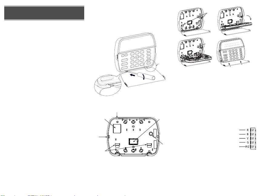
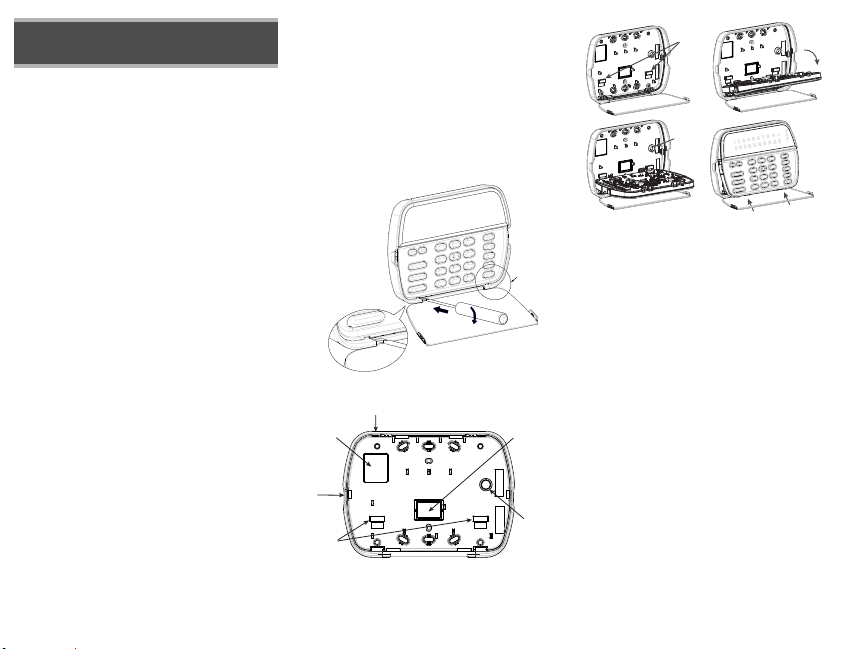
RED
BLK
YEL
GRN
To zone or
PGM output
Installation Instructions
The PK55XX\RFK55XX keypads can be used on security systems with
up to 64 zones. These keypads are compatible with the latest version
of the folllowing DSC security systems:
•PC580 •PC585 •PC1555MX •PC1565
•PC1616 •PC1832 •PC1864 •PC5005
•PC5008 •PC5010 •PC5015 •PC5016
•PC5020
The RFK55XX keypads combine a wireless receiver with the respective
PK55XX keypad.
Specifications
• Temperature range: -10°C to +55°C (14°F to 131°F), Temperature
range for UL/ULC: 0°C to +49°C (32°F to 120°F)
• Humidity (MAX): 93%R.H.
• Plastic enclosure protection degree: IP30, IK04
• Voltage rating: 12V
• Connects to control panel via 4-wire Keybus
• 1 keypad zone input/PGM output*
• PK55XX Current draw: 50mA (standby)/125mA (maximum)
• RFK55XX Current draw: 75mA (standby)/135mA (maximum)
• Wall mount tamper
• 5 programmable function keys
• Ready (Green LED), Armed (Red LED), Trouble (Yellow LED), AC
(Green LED)
• Low temperature sensor
• Frequency: 433.92MHz (RFK55XX-433)/868MHz (RFK55XX-868**)
• Up to 32 wireless zones (RFK55XX Only)
*Zone not to be programmed as Fire type or 24h type.
**NOTE: RFK55xx-868 models not UL listed.
Unpacking
The Power keypad package includes the following parts:
•One Power keypad •Keypad inner door labels
DC nominal
•Four mounting screws •1 tamper switch
•2 end-of-line resistors •Installation Instructions
Mounting
You should mount the keypad where it is accessible to designated
points of entry and exit. Once you have selected a dry and secure location, perform the following steps to mount the keypad.
Disassemble Keypad
1. Insert a flat head screwdriver into the provided slot (first of two)
2. Move screwdriver toward the back plastic and lift as in the below diagram. This will unhook one side of the front plastic.
3. Repeat step # 1 and 2 on the second provided slot to disconnect the
front plastic and allow access for wiring.
3
1
2
Mount and Wire Keypad
Knock Out
Wiring Slot
Knock Out
Hooks
Knock Out
Tamper
1.
3.
1. Secure Keypad to wall using mounting holes. Use all 4 screws provided
unless mounting on a single gang box.
2. Place keypad into hooks on the backplate and swing down to engage.
3. Run wire through wiring slot or knockouts. Connect Keybus and PGM/Zone
wiring to keypad. Place tamper switch into tamper hole on backplate.
4. Remove keypad from hooks. Place keypad into backplate, ensure the wire
is pushed back into the wall as much as possible. Route the wire inside the
keypad ensuring high components are avoided. Snap the front assembly
closed, ensuring that there is no pressure to the keypad from the wire
below.
NOTE: If any tension found between the front keypad assembly and wiring,
please open the keypad reroute the wire and close again. Repeat these
steps until the keypad is closed pr operly.
Wiring
1. Before wiring the unit, ensure that all power
(AC transformer and battery) is disconnected
from the control panel.
2. Connect the four Keybus wires from the control panel (red, black, yellow and green) to
the keypad terminals. Refer to diagram:
3. If programmed as an input, you can connect
a device - such as a door contact - to the ‘P/
Z’ terminal of the keypad. This eliminates the need to run wires back to
the control panel for the device. To connect the zone, run one wire from the
device to the ‘P/Z’ terminal and the other wire from the device to the B
(black) terminal. For powered devices, run the red wire to the R (positive)
terminal and the black wire to the B (negative) terminal. When using end
of line supervision, connect the zone according to one of the configurations
outlined in your system’s Installation Manual.
4. If the ‘P/Z’ terminal is programmed as an output, the output follows the
PGM programmed in Section [080]. A small relay, buzzer or other DC
Hooks
Tam p e r
2.
4.
Press to Snap
Swing
to engage
operated device may be connected between the positive supply voltage
41
Toggle Option
1 _ _ 4 _ _ _ _
and the ‘P/Z’ terminal (maximum load is 50mA).
NOTE: For UL Residential Fire Installations use at least one additional DSC
compatible keypad in conjunction with an RFK55XX keypad or install the
RFK55XX keypads within 3 feet from the control unit and mechanically protect the keybus wires
Applying Power
Once all wiring is complete, and the equipment is secured to the building
structure with at least two screws apply power to the control panel:
1. Connect the battery leads to the battery.
2. Connect the AC transformer.
For more information on control panel power specifications, see the control
panel Installation Manual.
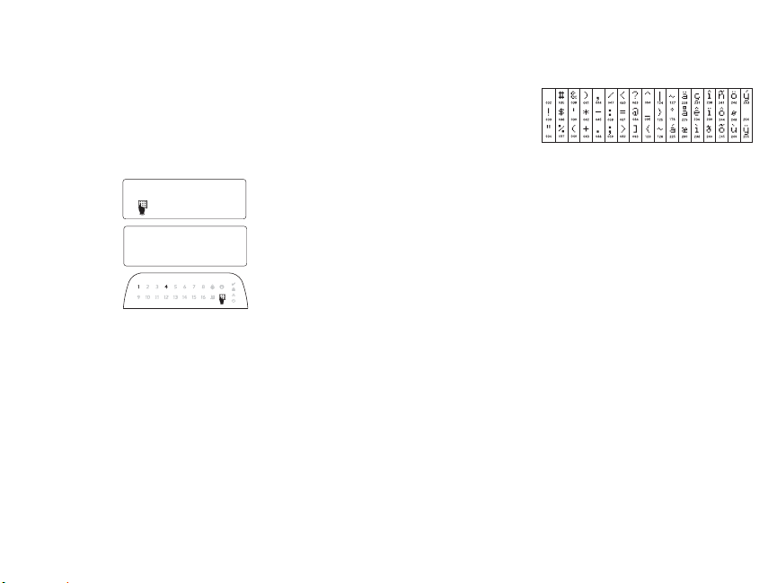
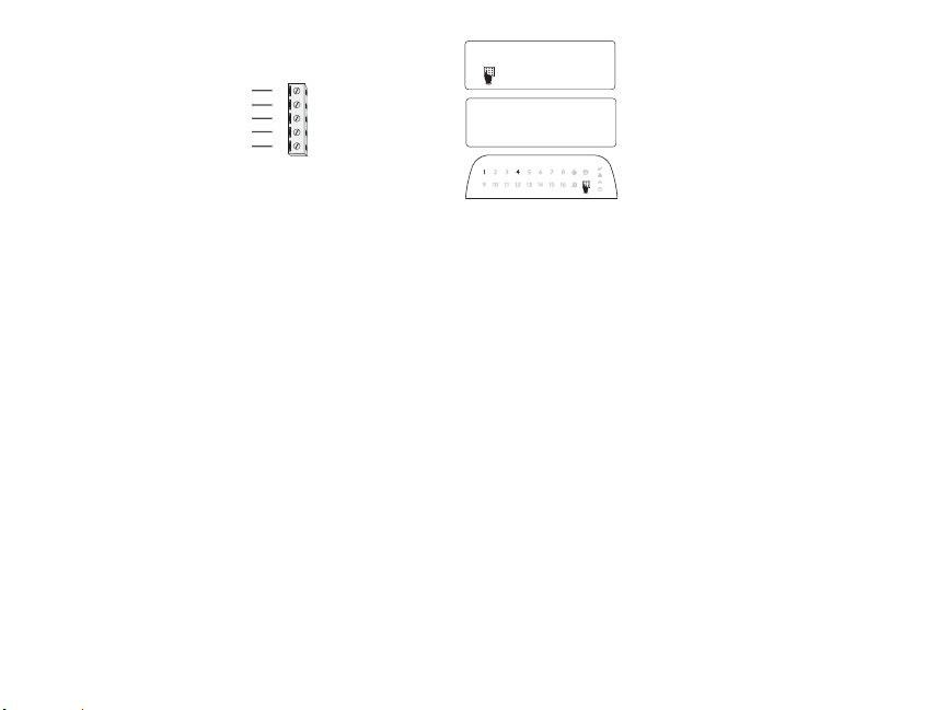
Programming the Keypad
There are several programming
options available for the keypad.
These are described below. Programming the keypad is similar
to programming the rest of the
system. When you are in the keypad programming sections, the
keypad will display which
options are turned on along the
top of the display. To turn an
option on or off, press the number corresponding to the option
on the number pad. The numbers of the options that are currently turned
ON will be displayed. For example, if options 1 and 4 are on, the display
will look like diagram shown on the different keypad displays.
For information on programming the rest of your security system, please
refer to your system’s Installation Manual.
Broadcasting LCD Labels
All LCD programming is done per keypad. If more than one LCD keypad is
present on the system, labels programmed at one keypad can be broadcast
to all other LCD keypads. Perform the following procedure in order to broadcast labels:
Step 1 - Program one LCD keypad completely.
Step 2 - Make sure all LCD keypads are connected to the Keybus.
Step 3 - Enter keypad programming by pressing [][8][Installer
Code][], then enter section [998] at the keypad that was programmed.
The keypad will now broadcast all the information programmed to all the
other LCD keypads on the system.
Step 4 - When the keypad is finished press the [#] key to exit.
NOTE: LCD Label broadcast from this keypad is only compatible
with PC1616/1832/1864 systems and PK5500/RFK5500 keypads.
Language Programming
(PK5500\RFK5500 Only)
Hold (<>) keys for 2 seconds to enter language programming, scroll to
the desired language and Press [] to select.
NOTE: If section [077] option 4 is OFF, language programming
can only be performed while in installers programming.
Enrolling the Keypad
The keypad will need to be assigned to a partition and slot if supervision or
keypad zones are being used. Keypad assignments and keypad option programming must be done at each keypad individually.
The 1st digit of keypad assignment is used to determine partition assignment (1 to 8). If partitioning is not used, enter [1]. For Global Keypads,
enter [0].
NOTE: LED and ICON keypads cannot be programmed as Global Keypads
The 2nd digit of keypad assignment is used to determine slot assignment
for keypad supervision. Each keypad will be assigned a different slot number from 1 to 8. PK5500 and RFK5500 LCD keypads come defaulted in slot
8. If LCD keypads are used one LCD keypad must remain in slot 8.
NOTE: The RFK55XX enrolls as two modules:
Light 1 = keypad section of the RFK55XX
Light 17 = receiver section of the RFK55XX
NOTE: Deleting all wireless devices from the RFK55XX or defaulting the
RFK55XX will cause a supervisory fault.
Enter the following at each keypad installed on the system:
1. Enter Installer Programming by pressing [][8][Installer’s Code]
2. Press [000] for Keypad Programming
3. Press [0] for Partition and Slot Assignment
4. Enter the 1st digit (0 to 8 for partition assignment)
5. Enter the 2nd digit (1 to 8 for slot assignment supervision)
6. Press the [#] key twice to exit programming.
7. After assigning all keypads, perform a supervisory reset by entering
[][8][Installer’s Code][902] and wait for 60 seconds.
8. Press the [#] key to exit programming after 60 seconds.
Programming Labels
(PK5500\RFK5500 Only)
1. Enter keypad programming by pressing [][8][Installer Code][]. Enter
the 3-digit section number for the label to be programmed.
2. Use the arrow keys (<>) to move the underline bar underneath the letter to be changed.
3. Press the number keys [1] to [9] corresponding to the letter you require.
The first time you press the number the first letter will appear. Pressing the
number key again will display the next letter
[1] - A, B, C, 1 [4] - J, K, L, 4 [7] - S, T, U, 7 [0] - Space
[2] - D, E, F, 2 [5] - M, N, O, 5 [8] - V, W, X, 8
[3] - G, H, I, 3 [6] - P, Q, R, 6 [9] - Y, Z, 9,0
.
4. When the required letter or number is displayed use the arrow keys
(<>) to scroll to the next letter.
5. When you are finished programming the Zone Label, press the [] key,
scroll to “Save,” then press [].
6. Continue from Step 2 until all Labels are programmed.
ASCII Characters
Changing Brightness/Contrast
LCD Keypads
1. Press [][6][Master code].
2. Use the [<][>] keys to scroll to either Brightness Control or Contrast Control.
3. Press [] to select the setting you want to adjust.
4. a) ‘Brightness Control’: There are multiple backlighting levels. Use the [<][>]
keys to scroll to the desired level.
b) ‘Contrast Control’: There are 10 different display contrast levels. Use the
[<][>] keys to scroll to the desired contrast level.
5. To exit, press [#].
LED/ICON Keypads
1. Press [][6][Master Code].
2. Use the [>] key to move through the 4 different backlighting levels.
3. The level is automatically saved when you press [#] to exit.
Changing the Buzzer Level
LCD Keypads
1. Press [][6][Master Code].
2. Use the [<][>] keys to scroll to Buzzer Control.
3. There are 21 different levels, use the [<][>] keys to scroll to the desired level.
4. To exit, press [#].
LED/ICON Keypads
1. Press [][6][Master Code].
2. Use the [<] key to move through the 21 different buzzer levels.
3. The level is automatically saved when you press [#] to exit.
Broadcasting Door Chime
All door chime programming is done per keypad. If more than one keypad is
present on the system, door chime programmed at one keypad can be broadcast to all other keypads. Perform the following procedure in order to broadcast
door chime:
Step 1 - Program one keypad completely.
Step 2 - Make sure all keypads are connected to the Keybus.
Step 3 - Enter keypad programming by pressing [][8][Installer Code][], then
enter section [994] at the keypad that was programmed. The keypad will
now broadcast all the door chime information programmed to all the
other keypads on the system.
Step 4 - When the keypad is finished press the [#] key to exit.

LIMITED WARRANTY
Digital Security Controls (DSC) warrants that for a period of 12 months from
the date of purchase, the product shall be free of defects in materials and workmanship under normal use and that in fulfilment of any breach of such warranty,
DSC shall, at its option, repair or replace the defective equipment upon return of
the equipment to its repair depot. This warranty applies only to defects in parts
and workmanship and not to damage incurred in shipping or handling, or damage due to causes beyond the control of Digital Security Controls such as lightning, excessive voltage, mechanical shock, water damage, or damage arising
out of abuse, alteration or improper application of the equipment. The foregoing
warranty shall apply only to the original buyer, and is and shall be in lieu of any
and all other warranties, whether expressed or implied and of all other obligations or liabilities on the part of Digital Security Controls. Digital Security Controls neither assumes responsibility for, nor authorizes any other person
purporting to act on its behalf to modify or to change this warranty, nor to
assume for it any other warranty or liability concerning this product. In no
event shall Digital Security Controls be liable for any direct, indirect or consequential damages, loss of anticipated profits, loss of time or any other losses
incurred by the buyer in connection with the purchase, installation or operation
or failure of this product. WARNING: Digital Security Controls recommends
that the entire system be completely tested on a regular basis. However, despite
frequent testing, and due to, but not limited to, criminal tampering or electrical
disruption, it is possible for this product to fail to perform as expected. IMPOR-
TANT INFORMATION: Changes/modifications not expressly approved by
DSC could void the user’s authority to operate this equipment.
IMPORTANT - READ CAREFULLY: DSC Software purchased with
or without Products and Components is copyrighted and is purchased
under the following license terms:
• This End-User License Agreement (“EULA”) is a legal agreement between
You (the company, individual or entity who acquired the Software and any
related Hardware) and Digital Security Controls, a division of Tyco Safety
Products Canada Ltd. (“DSC”), the manufacturer of the integrated security
systems and the developer of the software and any related products or components (“HARDWARE”) which You acquired.
• If the DSC software product (“SOFTWARE PRODUCT” or “SOFTWARE”) is intended to be acc ompanied by HARDWARE, and is NOT accompanied by new HARDWARE, You may not use, copy or install the
SOFTWARE PRODUCT. The SOFTWARE PRODUCT includes computer
software, and may include associated media, printed materials, and “online” or
electronic documentation.
• Any software provided along with the Software Product that is associated
with a separate end-user license agreement is licensed to You under the terms of
that license agreement.
• By installing, copying, downloading, storing, accessing or otherwise using
the Software Product, You agree unconditionally to be bound by the terms of
this EULA, even if this EULA is deemed to be a modification of any previous
arrangement or contract. If You do not agree to the terms of this EULA, DSC is
unwilling to license the Software Product to You, and You have no right to use
it.
SOFTWARE PRODUCT LICENSE
The SOFTWARE PRODUCT is protected by copyright laws and international
copyright treaties, as well as other intellectual property laws and treaties. The
SOFTWARE PRODUCT is licensed, not sold.
1. GRANT OF LICENSE This EULA grants You the following rights:
(a) Software Installation and Use - For each license You acquire, You may
have only one copy of the SOFTWARE PRODUCT installed.
(b) Storage/Network Use - The SOFTWARE PRODUCT may not be
installed, accessed, displayed, run, shared or used concurrently on or from
different computers, including a workstation, terminal or other digital electronic
device (“Device”). In other words, if You have several workstations, You will
have to acquire a license for each workstation where the SOFTWARE will be
used.
(c) Ba ckup Copy - You may make back-up copies of the SOFTWARE
PRODUCT, but You may only have one copy per license installed at any given
time. You may use the back-up copy solely for archival purposes. Except as
expressly provided in this EULA, You may not otherwise make copies of the
SOFTWARE PRODUCT, including the printed materials accompanying the
SOFTWARE.
2. DESCRIPTION OF OTHER RIGHTS AND LIMITATIONS
(a) Limitations on Reverse Engineering, Decompilation and Disassembly
- You may not reverse engineer, decompile, or disassemble the SOFTWARE
PRODUCT, except and only to the extent that such activity is expressly
permitted by applicable law notwithstanding this limitation. You may not make
any changes or modifications to the Software, without the written permission of
an officer of DSC. You may not remove any proprietary notices, marks or labels
from the Software Product. You shall institute reasonable measures to ensure
compliance with the terms and conditions of this EULA.
(b) Separation of Components - The Software Product is licensed as a
single product. Its component parts may not be separated for use on more than
one HARDWARE unit.
(c) Single INTEGRATED PRODUCT - If You acquired this SOFTWARE
with HARDWARE, then the SOFTWARE PRODUCT is licensed with the
HARDWARE as a single integrated product. In this case, the SOFTWARE
PRODUCT may only be used with the HARDWARE as set forth in this
EULA..
(d) Rental - You may not rent, lease or lend the SOFTWARE PRODUCT.
You may not make it available to others or post it on a server or web site.
(e) Software Product Transf er - You may transfer all of Your rights under
this EULA only as part of a permanent sale or transfer of the HARDWARE,
provided You retain no copies, You transfer all of the SOFTWARE
PRODUCT (including all component parts, the media and printed materials,
any upgrades and this EULA), and provided the recipient agrees to the terms of
this EULA. If the SOFTWARE PRODUCT is an upgrade, any transfer must
also include all prior versions of the SOFTWARE PRODUCT.
(f) Termination - Without prejudice to any other rights, DSC may terminate
this EULA if You fail to comply with the terms and conditions of this EULA. In
such event, You must destroy all copies of the SOFTWARE PRODUCT and all
of its component parts.
(g) Trademarks - This EULA does not grant You any rights in connection
with any trademarks or service marks of DSC or its suppliers.
3. COPYRIGHT - All title and intellectual property rights in and to the
SOFTWARE PRODUCT (including but not limited to any images,
photographs, and text incorporated into the SOFTWARE PRODUCT), the
accompanying printed materials, and any copies of the SOFTWARE
PRODUCT, are owned by DSC or its suppliers. You may not copy the printed
materials accompanying the SOFTWARE PRODUCT. All title and intellectual
property rights in and to the content which may be accessed through use of the
SOFTWARE PRODUCT are the property of the respective content owner and
may be protected by applicable copyright or other intellectual property laws and
treaties. This EULA grants You no rights to use such content. All rights not
expressly granted under this EULA are reserved by DSC and its suppliers.
4. EXPORT RESTRICTIONS - You agree that You will not export or
re-export the SOFTWARE PRODUCT to any c ountry, person, or entity subject
to Canadian export restrictions.
5. CHOICE OF LAW - This Software License Agreement is governed by the
laws of the Province of Ontario, Canada.
6. ARBITRATION - All disputes arising in connection with this Agreement
shall be determined by final and binding arbitration in accordance with the
Arbitration Act, and the parties agree to be bound by the arbitrator’s decision.
The place of arbitration shall be Toronto, Canada, and the language of the
arbitration shall be English.
7. LIMITED WARRANTY
(a) NO WARRANTY - DSC PROVIDES THE SOFTWARE “AS IS”
WITHOUT WARRANTY. DSC DOES NOT WARRANT THAT THE
SOFTWARE WILL MEET YOUR REQUIREMENTS OR THAT
OPERATION OF THE SOFTWARE WILL BE UNINTERRUPTED OR
ERROR-FREE.
(b) CHANGES IN OPERATING ENVIRONMENT - DSC shall not be
responsible for problems caused by changes in the operating characteristics of
the HARDWARE, or for problems in the interaction of the SOFTWARE
©2010 Digital Security Controls, Toronto, Canada • www.dsc.com • Tech Support: 1-800-387-3630 (Canada, US), 905-760-3036
PRODUCT with non-DSC-SOFTWARE or HARDWARE PRODUCTS.
(c) LIMITATION OF LIABILITY; WARRANTY REFLECTS
ALLOCATION OF RISK - IN ANY EVENT, IF ANY STATUTE
IMPLIES WARRANTIES OR
LICENSE AGREEMENT, DSC’S ENTIRE LIABILITY UNDER ANY
PROVISION OF THIS LICENSE AGREEMENT SHALL BE LIMITED TO
THE GREATER OF THE AMOUNT ACTUALLY PAID BY YOU TO
LICENSE THE SOFTWARE PRODUCT AND FIVE CANADIAN
DOLLARS (CAD$5.00). BECAUSE SOME JURISDICTIONS DO NOT
ALLOW THE EXCLUSION OR LIMITATION OF LIABILITY FOR
CONSEQUENTIAL OR INCIDENTAL DAMAGES, THE ABOVE
LIMITATION MAY NOT APPLY TO YOU.
(d) DISCLAIMER OF WARRANTIES - THIS WARRANTY
CONTAINS THE ENTIRE WARRANTY AND SHALL BE IN LIEU OF
ANY AND ALL OTHER WARRANTIES, WHETHER EXPRESSED OR
IMPLIED (INCLUDING ALL IMPLIED WARRANTIES OF
MERCHANTABILITY OR FITNESS FOR A PARTICULAR PURPOSE)
AND OF ALL OTHER OBLIGATIONS OR LIABILITIES ON THE PART
OF DSC. DSC MAKES NO OTHER WARRANTIES. DSC NEITHER
ASSUMES NOR AUTHORIZES ANY OTHER PERSON PURPORTING
TO ACT ON ITS BEHALF TO MODIFY OR TO CHANGE THIS
WARRANTY, NOR TO ASSUME FOR IT ANY OTHER WARRANTY OR
LIABILITY CONCERNING THIS SOFTWARE PRODUCT.
(e) EXCLUSIVE REMEDY AND LIMITATION OF WARRANTY -
UNDER NO CIRCUMSTANCES SHALL DSC BE LIABLE FOR ANY
SPECIAL, INCIDENTAL, CONSEQUENTIAL OR INDIRECT DAMAGES
BASED UPON BREACH OF WARRANTY, BREACH OF CONTRACT,
NEGLIGENCE, STRICT LIABILITY, OR ANY OTHER LEGAL
THEORY. SUCH DAMAGES INCLUDE, BUT ARE NOT LIMITED TO,
LOSS OF PROFITS, LOSS OF THE SOFTWARE PRODUCT OR ANY
ASSOCIATED EQUIPMENT, COST OF CAPITAL, COST OF
SUBSTITUTE OR REPLACEMENT EQUIPMENT, FACILITIES OR
SERVICES, DOWN TIME, PURCHASERS TIME, THE CLAIMS OF
THIRD PARTIES, INCLUDING CUSTOMERS, AND INJURY TO
PROPERTY. WARNING: DSC recommends that the entire system be
completely tested on a regular basis. However, despite frequent testing,
and due to, but not limited to, criminal tampering or electrical disruption,
it is possible for this SOFTWARE PRODUCT to fail to perform as
expected.
FCC Compliance Statement - CAUTION: Changes or modifications
not expressly approved by DSC could void your authority to use this
equipment.
This equipment generates and uses radio frequency energy and if not installed
and used properly, in strict accordance with the manufacturer’s instructions,
may cause interference to radio and television reception. It has been type tested
and found to comply with the limits for Class B device in accordance with the
specifications in Subpart “B” of Part 15 of FCC Rules, which are designed to
provide reasonable protection against such interference in any residential installation. However, there is no guarantee that interference will not occur in a particular installation. If this equipment does cause interference to television or radio
reception, which can be determined by turning the equipment off and on, the
user is encouraged to try to correct the interference by one or more of the following measures:
• Re-orient the receiving antenna
• Relocate the alarm control with respect to the receiver
• Move the alarm control away from the receiver
• Connect the alarm control into a different outlet so that alarm control and
receiver are on different circuits.
If necessary, the user should consult the dealer or an experienced radio/television technician for additional suggestions. The user may find the following
booklet prepared by the FCC helpful: “How to Identify and Resolve Radio/
Television Interference Problems”. This booklet is available from the U.S. Government Printing Office, Washington, D.C. 20402, S tock # 004-000-00345-4.
Operating Instructions shall be made available to the user.
CONDITIONS NOT STATED IN THIS
Printed in Canada

Keypad Enrollment
Enter keypad programming by pressing [][8][Installer’s Code][000].
[0] Partition / Slot Assignment
Digit Option Valid Range Default
1st Partition Assignment (0=Global Keypad) 0 to 8 1 I_____I
2nd Slot Assignment 1 to 8 LED,ICON=1/LCD=8 I_____I
[1]-[5] Function Key Assignment
Function Key Button Valid Range Default Function
[1] Function Key 1 Assignment 00 to 32 03 Stay Arm I_____I_____I
[2] Function Key 2 Assignment 00 to 32 04 Away Arm I_____I_____I
[3] Function Key 3 Assignment 00 to 32 06 Chime On/Off I_____I_____I
[4] Function Key 4 Assignment 00 to 32 14 Sensor Reset I_____I_____I
[5] Function Key 5 Assignment 00 to 32 16 Quick Exit I_____I_____I
Keypad Function Keys
Refer to your system installation manual for a complete list of all function key options available for your system.
[00] - Null [08] - Bypass Mode [16] - Quick Exit [26] - Time & Date Program
[01] - Partition 1 Select [09] - Trouble Display [17] - Activate Stay/A way [27] - Partition 3 Select
[02] - Partition 2 Select [10] - Alarm Memory [18] - *Global Away Arm [28] - Partition 4 Select
[03] - Stay Arm [11] - User Programming [19] - Command Output 3 [29] - Partition 5 Select
[04] - Away Arm [12] - User Functions [21] - Command Output 4 [30] - Partition 6 Select
[05] - No Entry Arm [13] - Command Output 1 [22] - *Global Disarming [31] - Partition 7 Select
[06] - Chime On/Off [14] - Command Output 2 [23] - Bypass Recall [32] - Partition 8 Select
[07] - System Test [15] - *Global Stay Arm [2 4] - Bypass Group Recall [33] - Local PGM Activate
*Available only on the PC1616/PC1832/PC1864 version 4.2 or higher.
Keypad Programming
Enter keypad programming by pressing [][8][Installer Code][]
[001]-[064] Zone Label 1 to 64 (PK5500\RFK5500 Only)
ex. For Zone 1 enter section [001], for Zone 2 enter section [002] etc. Default: “Zone 1” - “Zone 64”
Section Zone Label
[001] to [064] 1 to 64
I_____I_____I_____I_____I_ ____I_____I_ ____I_____I_ ____I_____I___ __I_____I__ ___I_____I
I_____I_____I_____I_____I_ ____I_____I_ ____I_____I_____I_ ____I_____I_ ____I_____I_ ____I
[065] Fire Alarm Label (28 Characters) (PK5500\RFK5500 Only)
Default:“Fire Zone”
I_____I_____I_____I_____I_____I_____I_____I_____I_____I_____I_____I_____I_____I_____I
[065]
I_____I_____I_____I_____I_____I_____I_____I_____I_____I_____I_____I_____I_____I_____I
[066] Fail to Arm Event Message (PK5500\RFK5500 Only)
Default: “System Has Failed to Arm”
I_____I_____I_____I_____I_____I_____I_____I_____I_____I_____I_____I_____I_____I_____I_____I_____I
[066]
I_____I_____I_____I_____I_____I_____I_____I_____I_____I_____I_____I_____I_____I_____I_____I_____I
[067] Alarm When Armed Event Message (PK5500\RFK5500 Only)
Default: “Alarm Occurred While Armed < >”
I_____I_____I_____I_____I_____I_____I_____I_____I_____I_____I_____I_____I_____I_____I_____I_____I
[067]
I_____I_____I_____I_____I_____I_____I_____I_____I_____I_____I_____I_____I_____I_____I_____I_____I
[071] First User Display Mask
Default Option ON OFF
ON I____I 1 Hold [P]anic Key prompt ON Hold [P]anic Key prompt OFF
ON I____I 2 Auto-arm Control/Time prompt ON Auto-arm Control/Time prompt OFF
ON I____I 3 Quick Arm prompt ON Quick Arm prompt OFF
ON I____I 4 Interior Arm prompt ON Interior Arm prompt OFF
OFF I____I 5 Quick Exit prompt ON Quick Exit prompt OFF
OFF I____I 6 Thermo stat Control prompt ON Thermostat Control prompt OFF
OFF I____I 7 ACK All Trouble Prompt ON ACK All Trouble Prompt OFF
OFF I____I 8 Music Input prom pt ON Music Input prompt OFF
[072] Second User Display Mask
Default Option ON OFF
ON I____I 1 User-initiated Call-up prompt ON User-initiated Call-up prompt OFF
OFF I____I 2For Future Use
OFF I____I 3 Walk Test prompt ON Walk Test prompt OFF
ON I____I 4 Command Output#1 prompt ON Command Output#1 prompt OFF
ON I____I 5 Command Output#2 prompt ON Command Output#2 prompt OFF
OFF I____I 6 Command Output#3 prompt ON Command Output#3 prompt OFF
OFF I____I 7 Command Output#4 prompt ON Command Output#4 prompt OFF
OFF I____I 8For Future Use
[073] Download LCD Message Duration (PK5500\RFK5500 Only)
Default: 003 I_____I_____I_____I (Valid entries are 000-255), 000=Unlimited Message Disp.This
number represents the number of times the Downloaded message is cleared by pressing any key while the
message is up after timeout).
[074] Key Options
12
9
10
11
12
7
8
Default Option ON OFF
ON I____I 1 [F]ire Key Enabled [F]ire Key Disabled
ON I____I 2 [A]uxiliary Key Enabled [A]uxiliary Key Disabled
ON I____I 3 [P]anic Key Enabled [P]anic Key Disabled
OFF I____I 4-8 For Future Use
[076] First Keypad Options
Default Option ON OFF
ON I____I 1 Display Code when Programming Display “Xs” when Programming
ON I____I 2 Local Clock Display ON Local Clock Display OFF
OFF I____I 3 Local Clock Displays 24-hr Time Local Clock Displays AM/PM
ON I____I 4 Auto Alarm Memory Scroll Enabled Auto Alarm Memory Scroll Disabled
OFF I____I 5 Local Display of Temperature ON Local Display of Temperature OFF
ON I____I 6 Bypass Options prompt ON Bypass Options prompt OFF
OFF I____I 7For Future Use
OFF I____I 8 Auto-Scroll Open Zones ON Auto-Scroll Open Zones OFF
[077] Second Keypad Options
Default Option ON OFF
ON I____I 1 Chime Enabled for Zone Openings Chime Disabled for Zone Openings
ON I____I 2 Chime Enabled for Zone Closings Chime Disabled for Zone Closings
OFF I____I 3 5th Terminal is Keypad PGM Outpu t 5th Terminal is Keypad Zone Input
ON I____I 4 Language Selection Enabled Language Selection Disabled
OFF I____I 5 Power LED Enabled Power LED Disabled
ON I____I 6 Power LED indicates AC present Power LED indicates AC absent
ON I____I 7 Alarms always Displayed When Armed Alarms not Displayed When Armed
OFF I____I 8 Low Temperature Warning Enabled Low Temperature Warning Disabled
[080] PGM Terminal 1
I_______I _______I 1-14 Foll ow PGM Output Number, 15 Local PGM Pulse , 16 Local PGM Toggle
Default: 01
[082] Local PGM Output Pulse Activation Time
Default: 00 I_______I _______I Minutes (Valid Range 00-99)
Default: 05
I_______I _______I Seconds (Valid Range 00-99)
[101]-[108] Partition Labels
ex. For Partition 1 enter section [101], for Partition 2 enter section [102] etc.
Section Partition Label
[101] to [108] 1 to 8
NOTE: Partition 1 Label is also used as the System Label
(PK5500\RFK5500 Only)
I_____I_____I_____I_____I_____I_____I_____I_____I_____I_____I_____I_____I_____I_____I
I_____I_____I_____I_____I_____I_____I_____I_____I_____I_____I_____I_____I_____I_____I
[120]-[151] Command Output Labels (PK5500\RFK5500 Only)
Default: “Command_O/P_1” - “Command_O/P_4”
For Partition 1 Command O/P 1 to 4 enter [120] to [123] For Partition 5 Command O/P 1 to 4 enter [136] to [139]
For Partition 2 Command O/P 1 to 4 enter [124] to [127] For Partition 6 Command O/P 1 to 4 enter [140] to [143]
For Partition 3 Command O/P 1 to 4 enter [128] to [131] For Partition 7 Command O/P 1 to 4 enter [144] to [147]
For Partition 4 Command O/P 1 to 4 enter [132] to [135] For Partition 8 Command O/P 1 to 4 enter [148] to [151]
Section Part
[120]-[151] 1to8 1to4
[201]-[264] Door Chime Sound Programming
You can program the keypad to make up to four different door chime sounds for individual zones.
ex. For Zone 1 enter section [201], for Zone 2 enter section [202] etc.
Default Option ON OFF
ON I____I 1 6 Beeps Disabled
OFF I____I 2 “Bing-Bing” Sound Disabled
OFF I____I 3 “Ding-Dong” Sound Disabled
OFF I____I 4Alarm Tone Disabled
Cmd.
Output
I_____I_____I_____I_____I__ ___I_____I_ ____I_____I_ ____I_____I___ __I_____I__ ___I_____I
Label
I_____I_____I_____I_____I__ ___I_____I_ ____I_____I_ ____I_____I___ __I_____I__ ___I_____I
OFF I____I 5-8 For Future Use
[994][] Initiate Global Keypad Chime Broadcast
[995][] Reset Keypad Options to Factory Default
[996][] Label Default (PK5500\RFK5500 Only)
[997] View Software Version (PK5500\RFK5500 Only)
[998][] Initiate Global Label Broadcast (PK5500\RFK5500 Only)
[999][] Reset Keypad EEPROM to Factory Defaults
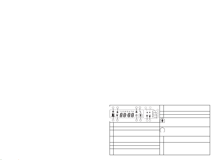
Keypad Display Symbols
1
1 Fire – Indicates that there are fire alarms in memory.
2 Memory – Indicates that there are alarms in memory.
Ready Light (green) – If the Ready light is on, the system
3
is ready for arming.
Armed Light (red) – If the Armed light is on, the system
4
has been armed successfully.
5 System Trouble – Indicates that a system trouble is active.
6 AC – Indicates that AC is present at the main panel.
Program – Indicates that the system is in Installer’s Pro-
7
gramming, or the keypad is busy.
8
Bypass – Indicates that there are zones automatically or
2
8
manually bypassed.
3
4
9 For Future Use
5
10 Arm Mode – Indicates the mode the panel is armed in.
6
7
Stay – Indicates that the panel is armed in the Stay
Mode. It will turn on at the beginning of the Exit
Delay
Away – Indicates that the panel is armed in the Away
Mode. It will turn on at the beginning of the Exit
Delay
Chime – This icon turns on when Door Chime is enabled on
11
the system and will turn off when Door Chime is disabled.
Open – When zones are opened, this icon will turn on, and
12
7 segment displays 1 and 2 will scroll through the open
zones.

Wireless Integration
(RFK55XX Only)
Compatible Wireless Devices (RFK55XX Only)
The RFK55XX can receive signals from the following devices:
• WLS912L-433 Glass Break Detector * • WS4945 Mini Door/Window Cont act*
• WLS914-433 Pet Immune PIR* • WS4965*/WS8965 Tri-Zone Contact
• WS4904(P)*/8904(P) Pet Immune • WS4969 Wireless Keys
• WS4916*/8916 Smoke Detector • WS4975/8975 Door/Window Contact
• WS4926 Smoke Detector* • WS4985/8985 Flood Detector
• WS4938 Panic Button* • WS4913*/8913 CO Detector**
• WS4939*/8939 Wireless Key
* Only these models are UL listed.
** CO Detector requires PC1616/1832/186 4 v4.3 or higher.
Downloading
The RFK55XX product has an integrated wireless receiver. When downloading to this keypad, please select the RF5132 v5.2 file. DLS2002 must
be used in order to have the capability of downloading to this keypad.
Testing Wireless Devices
1. Temporarily put the wireless devices in the places you want to mount
them.
2. At a system keypad, enter [][8][Installer Code].
3. Enter programming section [904], then enter the 2-digit zone number.
NOTE: If global placement test is enabled (Section [90], option 8
ON) enter [01] to test all zones.
4. Activate the device being tested until a result is displayed on the key-
pad or sounded by the keypad or bell
Result LED/ICON Keypad LC D Keypad Bell/ Buzzer
Good Light 1 ON Stea dy Good 1 Beep/Squawk
Bad Light 3 ON Steady Bad 3 Beeps/Squawks
While in placement test the Ready and Armed LEDs are used to indicate
the reception of a valid signal from a wireless device. The Green ( Ready)
LED indicates that a transmission was received from a device that is
enrolled on the system. The Red (Armed) LED indicates that a transmission was received from a device that is not enrolled on the system. The
corresponding LED will flash once per transmission.
Activate the device until you get 3 good results in a row. Wait 10 seconds between each test on the same device. You may mount wireless
devices where results were good.
Devices indicating a bad result must be moved to another location. You
may only have to move the device a few inches to correct a bad result.
NOTE: Do not mount any device where a “bad” test result was
indicated.
Testing Portable Device Reception
To test portable devices (e.g., WS49X9) press the button(s) at several
different points in the installation, to confirm the cov erage area. If these
devices do not operate from all points in the installation, you will need
to move the RFK55XX.
Replacing Wireless Device
Batteries
1. Remove the cover of the device from its backplate. This creates a
tamper condition on the zone.
2. Refer to the battery installation instructions on the Installation Sheet
of each component. Be sure to note the proper orientation of the
batteries as you install them.
3. When the fresh batteries are in place, re-attach the cover to the
backplate. The tamper is restored and the zone sends a battery
trouble restoral signal to the receiver. The battery trouble is now
clear and the device should function normally.
NOTE: When batteries in one device need to be replaced, the batteries in all devices should be replaced at the same time.
Troubleshooting
1. When I enter the 2-digit zone number when adding a wireless
device, the keypad gives me a long beep.
• You cannot enter ESNs unless the RFK55XX is properly connected to the
Keybus.
2. I have entered the ESN for the device but when I violate the device,
the zone does not show open on the keypad.
Check the following:
• Ensure the ESN has been entered correctly
• Ensure that the zone is enabled for the partition (if partition program-
ming is used).
• Ensure that the wireless zone is not assigned to a zone used by
PC5108 modules, an on-board zone or a keypad zone.
• Ensure that the zone is programmed for something other than “Null
Operation” and that the wireless zone attribute is turned on.
3. When I try a module placement test I get no result or “Bad” results.
Check the following:
• Verify that you are testing the correct zone
• Verify that the device is in range of the RFK55XX. Try testing the device
in the same room as the receiver.
• Confirm that the RFK55XX is properly connected to the Keybus.
• Check that you are testing the zone correctly. Refer to the instructions
that came with the zone.
• Check that the batteries are working and installed correctly.
• Look for large metal objects that may be preventing the signal from
reaching the RFK55XX.
• The device must be located where consistent “Good” results are
obtained. If several devices show “Bad” results, or if panic pendants
and wireless keys operate inconsistently, move the receiver.
4. The LED on the motion detector does not t urn on when I walk in front
of the unit.
• The LED on the motion detector is for walk test purposes only. See your
WS4904(P) Instruction Sheet for walk test instructions.
+HUHE\ '6& GHFODUHV WKDW WKLV GHYLFH LV LQ FRPSOLDQFH ZLWK WKH HVVHQWLDO
UHTXLUHPHQWVDQGRWKHUUHOHYDQWSURYLVLRQVRI'LUHFWLYH(&
7KH FRPSOHWH 577( 'HFODUDWLRQ RI &RQIRUPLW\ FDQ EH IRXQG DW
KWWSZZZGVFFRPOLVWLQJVBLQGH[DVS[
&=( '6& MDNR Y¿UREFH SURKODģXMH ŀH WHQWR Y¿UREHN MH Y VRXODGX VH YģHPL
UHOHYDQWQ¯PLSRŀDGDYN\VPÝUQLFH(&
'$1'6&HUNO¨UHUKHUYHGDWGHQQHNRPSRQHQWHQRYHUKROGHUDOOHYLNWLJHNUDY VDPW
DQGUHEHVWHPPHOVHUJLWWLGLUHNWLY(&
'87+LHUELM YHUNODDUW'6& GDWGLW WRHVWHOLQ RYHUHHQVWHPPLQJLV PHWGH HLVHQHQ
EHSDOLQJHQYDQULFKWOLMQ(&
),1'6&YDNXXWWDDODLWWHHQW¦\WW¦Y¦QGLUHNWLLYLQ(&ROHQQDLVHWYDDWLPXNVHW
)5(3DU ODSU«VHQWH '6& G«FODUHTXH FHGLVSRVLWLI HVWFRQIRUPH DX[ H[LJHQFHV
HVVHQWLHOOHVHWDXWUHVVWLSXODWLRQVSHUWLQHQWHVGHOD'LUHFWLYH(&
*(5+LHUGXUFKHUNO¦UW'6&GD¡GLHVHV*HU¦WGHQHUIRUGHUOLFKHQ%HGLQJXQJHQ XQG
9RUUDXVHW]XQJHQGHU5LFKWOLQLH(&HQWVSULFKW
*5(˂˜˞˱ˬ˲ ˭˞ˮ˹˪˱ˬ˯ˤ'6& ˡˤ˨˻˪ˢ˦˹˱˦ ˞˲˱˛ˤ˰˲˰˧ˢ˲˛ ˢ˜˪˞˦˰˺˩˳˶˪ˤ˩ˢ ˱˦˯
ˬ˲˰˦˻ˡˤ˯˞˭˞˦˱˛˰ˢ˦˯˧˞˦˩ˢ˹˨ˢ˯˱˦˯˙˨˨ˢ˯˰˴ˢ˱˦˧˚˯˞˪˞˳ˬˮ˚˯˱ˤ˯ˍˡˤˠ˜˞˯(&
,7$ &RQOD SUHVHQWH OD 'LJLWDO 6HFXULW\ &RQWUROV GLFKLDUD FKHTXHVWR SURGRWWR ª
FRQIRUPH DL UHTXLVLWL HVVHQ]LDOL HGDOWUH GLVSRVL]LRQL ULOHYDQWL UHODWLYH DOOD 'LUHWWLYD
&(
125'6&HUNO¨UHUDWGHQQH HQKHWHQHULVDPVYDUPHGGH JUXQQOHJJHQGHNUDYRJ
ºYULJHUHOHYDQWHNUDYLGLUHNWLY()
32/'6&RĝZLDGF]DľHXU]ÇG]HQLHMHVWZ]JRGQRĝFL]]DVDGQLF]\PLZ\PDJDQLDPL
RUD]SR]RVWDĄ\PLVWRVRZQ\PLSRVWDQRZLHQLDPL'\UHNW\Z\:(
3253RUHVWH PHLRD'6&GHFODUD TXHHVWHHTXLSDPHQWRHVW£ HPFRQIRUPLGDGH
FRP RV UHTXLVLWRV HVVHQFLDLV H RXWUDV GHWHUPLQD©·HV UHOHYDQWHV GD 'LUHFWLYD
(&
63$3RU ODSUHVHQWH'6& GHFODUDTXH HVWHHTXLSR HVW£HQ FRQIRUPLGDGFRQORV
UHTXLVLWRVHVHQFLDOHV\RWURVUHTXLVLWRVUHOHYDQWHVGHOD'LUHFWLYD(&
6:('6&EHNU¦IWDU K¦UPHGDWW GHQQDDSSDUDWXSSI\OOHU GHY¦VHQWOLJD NUDYHQRFK
DQGUDUHOHYDQWDEHVW¦PPHOVHUL'LUHNWLYHW(&
This Class B digital apparatus complies with Canadian ICES-003.
Cet appareil numérique de la classe B est conforme à la norme NMB003 du Canada.
IC:160A-RFK55XX4
The term IC before the radio certification number signifies that the
Industry Canada technical specifications were met.
EN50131-1 Grade2/Class II

Wireless Programming (RFK55XX Only)
Enter Wireless programming by pressing [][8][Installer’s Code][804]
[01]-[32] Wireless Device Serial Number
[01] Zone 1 I_____I_____I_____I_____I_ ____I_____I [17] Zone 17 I_____I_____I_____I_____I _____I_____I
[02] Zone 2 I_____I_____I_____I_____I_ ____I_____I [18] Zone 18 I_____I_____I_____I_____I _____I_____I
[03] Zone 3 I_____I_____I_____I_____I_ ____I_____I [19] Zone 19 I_____I_____I_____I_____I _____I_____I
[04] Zone 4 I_____I_____I_____I_____I_ ____I_____I [20] Zone 20 I_____I_____I_____I_____I _____I_____I
[05] Zone 5 I_____I_____I_____I_____I_ ____I_____I [21] Zone 21 I_____I_____I_____I_____I _____I_____I
[06] Zone 6 I_____I_____I_____I_____I_ ____I_____I [22] Zone 22 I_____I_____I_____I_____I _____I_____I
[07] Zone 7 I_____I_____I_____I_____I_ ____I_____I [23] Zone 23 I_____I_____I_____I_____I _____I_____I
[08] Zone 8 I_____I_____I_____I_____I_ ____I_____I [24] Zone 24 I_____I_____I_____I_____I _____I_____I
[09] Zone 9 I_____I_____I_____I_____I_ ____I_____I [25] Zone 25 I_____I_____I_____I_____I _____I_____I
[10] Zone 10 I_____I_____I___ __I_____I_____I_____I [26] Zone 26 I_____I_____I_____I_____I___ __I_____I
[11] Zone 11 I_____I_____I___ __I_____I_____I_____I [27] Zone 27 I_____I_____I_____I_____I___ __I_____I
[12] Zone 12 I_____I_____I___ __I_____I_____I_____I [28] Zone 28 I_____I_____I_____I_____I___ __I_____I
[13] Zone 13 I_____I_____I___ __I_____I_____I_____I [29] Zone 29 I_____I_____I_____I_____I___ __I_____I
[14] Zone 14 I_____I_____I___ __I_____I_____I_____I [30] Zone 30 I_____I_____I_____I_____I___ __I_____I
[15] Zone 15 I_____I_____I___ __I_____I_____I_____I [31] Zone 31 I_____I_____I_____I_____I___ __I_____I
[16] Zone 16 I_____I_____I___ __I_____I_____I_____I [32] Zone 32 I_____I_____I_____I_____I___ __I_____I
[41]-[56] Wireless Key Serial Number
[41] Key 1 I_____I_____I_____I_____I_____I___ __I [49] Key 9 I_____I_____I_____ I_____I_____I_____I
[42] Key 2 I_____I_____I_____I_____I_____I___ __I [50] Key 10 I_____I_____I_____I_____I_ ____I_____I
[43] Key 3 I_____I_____I_____I_____I_____I___ __I [51] Key 11 I_____I_____I_____I_____I_ ____I_____I
[44] Key 4 I_____I_____I_____I_____I_____I___ __I [52] Key 12 I_____I_____I_____I_____I_ ____I_____I
[45] Key 5 I_____I_____I_____I_____I_____I___ __I [53] Key 13 I_____I_____I_____I_____I_ ____I_____I
[46] Key 6 I_____I_____I_____I_____I_____I___ __I [54] Key 14 I_____I_____I_____I_____I_ ____I_____I
[47] Key 7 I_____I_____I_____I_____I_____I___ __I [55] Key 15 I_____I_____I_____I_____I_ ____I_____I
[48] Key 8 I_____I_____I_____I_____I_____I___ __I [56] Key 16 I_____I_____I_____I_____I_ ____I_____I
Zone Serial Numbers Default = 000000
Wireless Key Serial Numbers Default = 000000
[61]-[76] Wireless Function Key Options
Function 1
Function 2
Function 3
Default 03
Default 04
I_____I_____I I_____I_____I I_____I_____I I_____I_____I
Key 1
[61]
I_____I_____I I_____I_____I I_____I_____I I_____I_____I
Key 2
[62]
I_____I_____I I_____I_____I I_____I_____I I_____I_____I
Key 3
[63]
I_____I_____I I_____I_____I I_____I_____I I_____I_____I
Key 4
[64]
I_____I_____I I_____I_____I I_____I_____I I_____I_____I
Key 5
[65]
I_____I_____I I_____I_____I I_____I_____I I_____I_____I
Key 6
[66]
I_____I_____I I_____I_____I I_____I_____I I_____I_____I
Key 7
[67]
I_____I_____I I_____I_____I I_____I_____I I_____I_____I
Key 8
[68]
Default 27
Function 4
Default 30
Function 1
Default 03
I_____I_____I I_____I_____I I_____I_____I I_____I_____I
Key 9
[69]
I_____I_____I I_____I_____I I_____I_____I I_____I_____I
Key 10
[70]
I_____I_____I I_____I_____I I_____I_____I I_____I_____I
Key 11
[71]
I_____I_____I I_____I_____I I_____I_____I I_____I_____I
Key 12
[72]
I_____I_____I I_____I_____I I_____I_____I I_____I_____I
Key 13
[73]
I_____I_____I I_____I_____I I_____I_____I I_____I_____I
Key 14
[74]
I_____I_____I I_____I_____I I_____I_____I I_____I_____I
Key 15
[75]
I_____I_____I I_____I_____I I_____I_____I I_____I_____I
Key 16
[76]
Function 2
Default 04
Function 3
Default 27
Function 4
Default 30
Keypad Function Keys
Please see your system installation m anual for a complete list of all the function key option s available for your system.
[00] - Null [07] - System Test [17] - Activate Stay/Away [27] - Disarm
[03] - Stay Arm [13] - Command Output 1 [18] - Global Away Arm [28] - Fire Alarm
[04] - Away Arm [14] - Command Output 2 [19] - Command Output 3 [29] - A uxiliary Alarm
[05] - No Entry Arm [15] - Global Stay Arm [21] - Command Output 4 [30] - Panic Alarm
[06] - Chime On/Off [16] - Quick Exit [22] - Global Disarm [31] - Local PGM Activate
NOTE: Wireless keys must have an access code for global arm/disarm function.
[77] Wireless Keys (1-16) Partition Assignments Default = 01
Key 1 I_____I___ __I Key 5 I_____I_____I Key 9 I___ __I_____I Key 13 I_____I_____I
Key 2 I_____I___ __I Key 6 I_____I_____I Key 10 I_____I_____I Key 14 I_____I_____I
Key 3 I_____I___ __I Key 7 I_____I_____I Key 11 I_____I_____I Key 15 I_____I_____I
Key 4 I_____I___ __I Key 8 I_____I_____I Key 12 I_____I_____I Key 16 I_____I_____I
[81] Wireless supervisory Window
Default: [NA] 96 = 24 hours / [EU] 10 =2.5 hours I_____I_____I
The window is programmed in 15 minute increments. Valid entries are 10 to 96, equal to 2.5 to 24 hours.
[82]-[85] Zone Device Supervision Options
[82]
Zone
Supervision
Default ON
Option 1 1 I_____I 9 I_____I 17 I_____I 25 I_____I
Option 2 2 I_____I 10 I_____I 18 I_____I 26 I_____I
Option 3 3 I_____I 11 I_____I 19 I_____I 27 I_____I
Option 4 4 I_____I 12 I_____I 20 I_____I 28 I_____I
Option 5 5 I_____I 13 I_____I 21 I_____I 29 I_____I
Option 6 6 I_____I 14 I_____I 22 I_____I 30 I_____I
Option 7 7 I_____I 15 I_____I 23 I_____I 31 I_____I
Option 8 8 I_____I 16 I_____I 24 I_____I 32 I_____I
ON/OFF
[83]
Zone
Supervision
ON/OFF
[84]
Zone
Supervision
ON/OFF
[85]
Zone
Supervision
ON/OFF
[90] Other Options
NA Default EU Default Option ON OFF
OFF OFF I____I 1,2,4 For Future Use
ON OFF I____I 3 Wall Tamper Disabled Wall Tamper Enabled
ON OFF I____I 5 RF Delinq uency Disabled RF Delinquency Enabled
OFF OFF I____I 6For Future Use
ON OFF I____I 7 RF Jam Detect Disabled RF Jam Detect Enabl ed
OFF OFF I____I 8 Global Place ment Test Individual Placement Test
NOTE: For UL Listed installations, the RF Jam detect feature must be enabled.
NOTE: For DD243 installations, the RF delinquency feature should be enabled.
NOTE: Supervision must be enable d for RF Delinquency.
[93] RF Jam Detect Zone
Default: 00 I_____I_____I Valid entries = 01 - 32, 00 = No RF Jam tone selected.
Select an unused zone that will be set to the tamper state when a jamming signal is detected.
Français
1
2
3
Faites
basculer
pour engager
Appuyer pour fermer
1.
2.
3.
4.
antisabotage
crochets
Instructions d’Installation
Les claviers PK55XX\RFK55XX peuvent être utilisés avec des systèmes
de sécurité ayant un maximum de 64 zones. Ces claviers sont compatibles avec la dernière version des centrales d'alarme DSC suivantes:
•PC580 •PC585 •PC1555MX •PC1565
•PC1616 •PC1832 •PC1864 •PC5005
•PC5008 •PC5010 •PC5015 •PC5016
•PC5020
Les claviers RFK55XX combinent un récepteur sans fil avec le clavier
PK55XX correspondant.
Spécifications
• Plage de température: -10°C à +55°C (14°F to 131°F) Plage de
température pour UL/ULC: 0°C to +49°C (32°F to 120°F)
• Humidité (MAX): HR 93 %
• Degré de protection boîtier plastique : IP30, IK04
• Tension nominale : 12 Vc.c
• Raccordement au panneau de contrôle via le Keybus à 4 fils.
• Une entrée de zone et une sortie PGM*
• PK55XX Consommation de courant : 50mA (en veille) /125 mA (max)
• RFK55XX Consommation de courant: 75mA (en veille)/135mA (max)
• Installation murale anti-sabotage
• Cinq touches de fonctions programmables
• Voyants d’état Prêt (vert), et Armé (rouge), Trouble (LED Jaune), AC
(LED) vert
• Capteur de basse température
• Fréquence: 433.92MHz (RFK55XX-433 )/868MHz (RFK55XX-868)
• 32 zones sans fil (Seulement RFK55XX )
* REMARQUE: Zone ne doit pas être programmée comme une
zone de type incendie (Feu) ou 24 h.
Déballage
La boîte du Power contient les éléments suivants:
•Un clavier
•Quatre vis de montage
•Deux résistance fin de lignes
•Un étiquette intérieure pour la porte du clavier
•Un commutateur anti-sabotage
•Un Manuel d’Installation
Montage
Pour le montage du clavier, choisissez un endroit près du point
d’entrée qui est sec, sécuritaire et ac cessible. Lorsque vous avez déterminé l’emplacement de montage, suivez les étapes suivantes.
Désassemblez le clavier
1. Insérez un tournevis plat dans la fente prévue (première fente des
deux).
2. Enfoncez le tournevis comme décrit dans le schéma ci-dessous. Cela
vous permettra de détacher une côté de la face avant.
3. Répétez étape 1 et 2 pour la deuxième fente pour enlever la face
avant du clavier afin de permettre le câblage.
Montage et câblage du clavier
alvéole défonçable
fente de câblage
alvéole
défonçable
crochets
alvéole
défonçable
anti-sabotage
1. Fixez le clavier à l’aide des trous de montage. Utilisez les 4 vis fournies à moins de faire le montage sur une seule boîte électrique.
2. Placez le clavier sur les crochets de la plaque arrière et faites basculer vers le bas pour engager.
3. Faites passez les fils dans la fente de câblage ou dans les alvéoles
défonçables. Connectez le câblage de zone Keybus et PGM au clavier. Placez l’interrupteur anti-sabotage dans le trou à cet effet sur
la plaque de montage.
4. Retirez le clavier des crochets Placez le clavier sur la plaque de montage en vous assurant que le fil est poussé dans le mur autant que
possible. Faites passer le fil à l’intérieur du clavier en vous assurant
d’éviter les éléments sensibles. Fermez l’assemblage avant en vous
assurant que le clavier ne fait pas pression sur le fil qui est dessous.
REMARQUE : S’il y a une tension quelco nque entre l’assemblage avant du
clavier et le câblage, ouvrez le clavier, déplacez le fil et refermer. Répétez
ces étapes jusqu’à ce que le clavier soit bien fermé.
Câblage
PK55XX\RFK55XX
Rouge
Noir
Jaune
Vert
L‘entree de zone
sortie PGM
R
B
Y
G
P/Z
41
Toggle Option
1 _ _ 4 _ _ _ _
1. Avant de commencer à câbler l’unité, assurez-vous que l’alimentation
(transformateur c.a. et batterie) du panneau de contrôle est coupée.
2. Raccordez les quatre fils du Keybus qui
proviennent du panneau de contrôle
(rouge, noir, jaune et vert) sur les bornes
(R, B, Y et G) du clavier. Référez-vous au
schéma ci-dessous:
3. Si la borne ‘Z/P ’ du PK55xx est programmée en tant qu’entrée, vous pouvez raccorder un dispositif sur cette borne, comme par exemple un contact de
porte. Ceci est un bon moyen d’économiser du temps et du câblage en
évitant d’avoir à installer un câble entre le panneau de contrôle et le
contact de la porte qui se trouve à proximité du clavier. Pour raccorder
la zone, installez un câble entre le dispositif et le clavier et raccordez
un des fils provenant du dispositif sur la borne ‘Z/P ’ du clavier et un
autre sur la borne B. Si le dispositif doit être alimenté, raccordez le fil
rouge à la borne R (positif) et le fil noir à la borne B (négatif). Si une
résistance de fin de ligne doit être utilisée, raccordez la zone en vous
conformant à l’une des configurations décrites dans le manuel
d’installation du système.
4. Si la borne ‘Z/P’ est programmée en tant que sortie, celle-ci suit la
programmation de la sortie PGM programmée dans la section de programmation de clavier numérique [080]. Un petit relais, un avertisseur sonore ou un autre dispositif qui fonctionne sous tension c.c. peut
être raccordé entre la borne d’alimentation positive et la borne ‘Z/P’
(consommation maximale de courant de 50mA).
REMARQUE : Pour les installations incendie homologuées UL,
utilisez au moins un clavier compatible DSC supplémentaire en
association avec le clavier RFK55XX ou installez les claviers
RFK55XX à moins de 3 pieds de l'unité de commande et protégez
mécaniquement les fils du bus de communication
Mise sous tension
Une fois que le câblage est fini et que le dispositif est fixé à la structure
de l’édifice avec au moins deux vis, mettez le panneau de contrôle sous
tension :
1. Raccordez les câbles de batterie à la batterie.
2. Branchez le transformateur CA.
Pour de plus amples informations sur les spécifications d’alimentation
du panneau de contrôle, référez-vous au manuel d’installation du panneau de contrôle.
Programmation du clavier
Plusieurs options de programmation sont disponibles pour le
clavier. La programmation du
clavier est similaire à celle du
reste du système. Lorsque vous
êtes dans le mode de programmation du clavier, l’afficheur du
clavier vous indique quelles sont
les options qui sont activées.
Pour activer ou désactiver une
option, appuyez sur la touche
numérique qui correspond au numéro de l’option. Les numéros
d’options qui apparaissent dans le haut de l’afficheur correspondent
aux options qui sont activées. Par exemple, si les options 1 et 4 sont
activées, l’afficheur aura l’air de ceci:
Pour l’information sur programmer le reste de votre système de sécurité,
référez-vous au manuel de l’installation de votre système.
Diffusion étiquettes LCD
Toute la programmation ACL est faite par clavier. Si plus d’un clavier
ACL est présent sur le système et si le PC5400 reçoit des intitulés, les
intitulés programmés à un clavier seront diffusés à tous les autres claviers ACL. Suivez la démarche suivante pour diffuser les intitulés:
Étape 1 - Programmez complètement un clavier ACL.
Étape 2 - Assurez-vous que tous les claviers ACL sont connectés sur le
KEYBUS.
Étape 3 - Entrez [][8][code de l’installateur][] pour accéder à la
programmation du clavier, puis dans la section [998] au clavier déjà
programmé. Le clavier diffusera tous les renseignements programmés
aux autres claviers ACL sur le système.
Étape 4 - Lorsque la diffusion est achevée, appuyez sur la touche [#]
pour sortir.
REMARQUE : La diffusion d’étiquette ce clavier est seulement compatibleavec la centrale PC1616/PC1832/PC1864 et les claviers PK5500/
RFK5500.
Programmation de langue
(Seulement PK5500\RFK5500)
Maintenir les touches (<>) pendant 2 secondes pour entrer le langage de programmation, faites défiler jusqu’au langage désiré et
appuyez sur [
] pour choisir.
REMARQUE : Si l’option 4 de la section [077] option 4 est désactivée, le langage de programmation ne peut se faire que dans la
programmation de l’installateur.
Attribution du clavier
Le clavier devra être assigné à une partition et à un emplacement si les
zones de supervision ou de clavier sont occupées. L’attribution du clavier et l’option de programmation de clavier doivent être faites individuellement à chaque clavier.
Le 1er chiffre de l’attribution du clavier est utilisé pour déterminer
l’attribution de la partition (1 à 8). S’il n’y a pas de partitionnement,
tapez [1]. Pour les claviers globau x, tapez [0].
REMARQUE : Les claviers LED et ICON ne peuvent pas être programmés
comme claviers globaux.
Le 2e chiffre de l’attribution du clavier est utilisé pour déterminer l’attribution de l’emplacement pour le clavier de supervision. On assigne à
chaque clavier un numéro d’emplacement différent, de 1 à 8. Les clavier ACL PK5500 et RFK5500 LCD sont par défaut assignés à l’emplacement 8. Si les claviers LCD sont utilisés un clavier LCD doit être assigné
à l’emplacement 8.
REMARQUE : Le RFK55XX est attribué en tant que deux modules :
Voyant 1 = section clavier du RFK55XX
Voyant 17 = section récepteur du RFK55XX
REMARQUE : L’annulation de tous les dispositifs sans fil du RFK55XX ou la
mise aux paramètres par défaut du RFK55XX provoquera une anomalie de
supervision.
Entrez ce qui suit pour chacun des claviers qui est installé dans le système:
1. Accédez au mode de programmation de l’installateur en entrant
[][8][code de l’installateur]
2. Entrez [00 0] pour accéder à la programmation du clavier.
3. Appuyez sur [0] pour accéder à l’attribution de la partition et de
l’emplacement de mémoire du clavier.
4. Entrez le 1er chiffre (0 à 8 pour l’attribution d’une partition)
5. Entrez le 2e chiffre (1 à 8 pour l’attribution de l’emplacement de
supervision)
6. Pour quitter le mode de programmati on, appuyez deux fois sur [#]
7. Après avoir assigné tous les claviers, effectuez une réinitialisation de
supervision en entrant [][8][code de l’installateur][902] et attendre 60 secondes.
8. Appuyez sur [#] pour sortir de la programmation après 60 secondes.

Programmation d’étiquette
(Seulement PK5500\RFK5500)
1. Entrez [][8][code de l’installateur][] pour accéder à la programmation du clavier. Entrez les trois chiffres de la section pour que
l’intitulé soit programmé.
2. Utilisez les touches flèches (<>) pour déplacer le trait bas sous la
lettre à changer.
3. Appuyez sur la touche du chiffre [1] à [9] correspondant à la lettre
requise. La première fois que vous appuyez sur le chiffre, la première
lettre apparaît. En appuyant à nouveau sur la touche chiffre vous
passerez à la lettre suivante.
[1] - A, B, C, 1 [4] - J, K, L, 4 [7] - S, T, U, 7 [0] - Espace
[2] - D, E, F, 2 [5] - M, N, O, 5 [8] - V, W, X, 8
[3] - G, H, I, 3 [6] - P, Q, R, 6 [9] - Y, Z, 9,0
4. L orsque vous devez afficher une autre lettre ou un autre chiffre utilisez
les touches flèches (<>) pour faire défiler jusqu’à la lettre suivante.
5.Lorsque vous avez fini la programmation de l’intitulé de zone,
appuyez sur la touche [], fait es défiler jusqu’à “Sauvegarde” puis
appuyez sur [].
6. Continuez à partir de l’étape 2 jusqu’à ce que tous les intitulés soient
programmés..
Caractères ASCII
Changer la luminosité et le contraste
Claviers LCD
1. Tapez [][6][code maître].
2. Utilisez les touches flèches [<>] pour le contrôle de la luminosité
ou du contraste.
3. Tapez [] pour sélectionner le paramètre que vous désirez ajuster.
4. a) “Contrôle de la luminosité” : Il y a 10 niveaux de rétro-éclairage.
Utilisez les touches flèches pour faire défiler jusqu'au niveau désiré.
b) “Contrôle du contraste” : Il y a 10 niveaux de contraste. Utilisez
les touches flèches pour faire défiler jusqu'au niveau de contraste
désiré.
5. Pour sortir de cette programmation, appuyez sur [#] .
Claviers LED/ICON
1. Tapez [][6][code maître].
2. Utilisez la touche [>] pour faire défiler les 4 niveaux de rétroéclairage.
3. Le niveau est sauvegardé automatiquement lorsque vous appuyez
sur [#] pour sortir.
Changement de volume du résonateur
Clavier LCD
1. Tapez [][6][code maître].
2. Utilisez [<][>] pour faire défiler jusqu'au niveau de sonorité
désiré.
3. Appuyez sur [] pour faire votre sélecti on.
4. Appuyez sur [#] pour sortir.
Claviers LED/ICON
1. Tapez [][6][code maître].
2. Utilisez la touche [<]pour faire défiler les 21 niveaux d’indicateur
sonore.
3. Le niveau est sauvegardé automatiquement lorsque vous appuyez
sur [#] pour sortir.
Transmission carillon de
porte
La programmation carillon de porte est faite par clavier. Lorsqu'il y a
plusieurs claviers dans le système, la fonction carillon de porte programmé sur un clavier peut être transmis vers tous les autres claviers.
Effectuez la procédure suivante pour la transmission de la fonction carillon de porte:
Etape 1 - Programmez un clavier entièrement
Etape 2 - Vérifiez si tous les claviers sont raccordé au keybus
Etape 3 - Entrez dans la programmation du clavier avec [*][8][code
installateur][*], puis entrez dans l'adresse [994] au clavier
qui a été programmé. Le clavier transmet maintenant la
programmation carillon de porte vers tous les autres claviers
dans le système.
Etape 4 - Quand le clavier est prêt, appuyez la touche [#] pour quitter.
Symboles d’affichage du clavier
9
12
12
7
Feu : cette icône indique que des alarmes d'incendie sont en
1
mémoire.
Mémoire : cette icône indique que des alarmes de vol sont en
2
mémoire.
Voyant Prêt (vert) – Si le voyant Prêt est allumé, le système est
3
prêt à être armé.
Voyant Armé (rouge) – Si le voyant Armé est allumé, le système a
4
été armé correctement.
Trouble du système : cette icône apparaît sur l’afficheur lorsqu’une
5
condition de trouble est présente dans le système.
AC – Cette icône indique que le central est alimenté par l’alimen-
6
tation c.a.
Programme : cette icône indique que le système est dans le mode
7
de programmation de l'installateur ou que le clavier est occupé.
Suspension : cette icône indique que des zone ont été manuelle-
8
ment ou automatiquement suspendues.
9
Non utilisé
10
Armé – le système est prêt à être armé en mode :
À domicile – cette icône indique que le système est armé en
mode A domicile. Elle s'allume au début du délai de sortie.
Absence – cette icône indique que le système est armé en
mode Absent. Elle s'allume au début du délai de sortie.
Carillon – Cette icône s’al lume lorsqu’un carillon de porte est activé
11
et s’éteint quand le carillon de porte est désactivé.
Ouvert -- Lorsque des zones sont ouvertes, cette icône s’allume et
12
les affichages 1 et 2 de 7 segments feront défiler les zones
ouvertes.
8
11
2
1
8
10
7
3
4
5
6

GARANTIE LIMITÉE
Digital Security Controls pendant une période de douze mois à partir de la
date d’achat, garantit le produit con tre toute défectuosité matérielle et
d’assemblage dans des conditions normales d’utilisation. Dans l’application de cette garantie, Digital Security Controls va, lorsqu’elle le juge
opportun, en cas de problèmes de fonctionnement, réparer ou remplacer les
équipements défectueux dès leur retour à son dépôt de réparation. Cette
garantie s’applique seulement aux éléments défectue ux et à la maind’œuvre, et non aux dommages causés lors de l’expédition ou de la manipulation, ni aux dommages dont les causes dépassent le contrôle de Digital
Security Controls telles que la foudre, les surtensions, les chocs mécaniques, les dégâts d’eau ou tout dommage provenant d’abus, de modifications ou de mauvaises utili sations de l’équipement. La garant ie susdite
n’est valide que pour l’acheteur origina l et n ’est et ne se ra qu e l a seule d es
garanties valables, qu’elle ait été expri mée ou implicite, rempl açant toute
autre obligation ou responsabilité de la part de Digital Security Controls.
La présente garantie contient la garantie au complet. Digital Security Controls. n’autorise aucune autre personne à agir en so n no m pour mo difi er ou
changer la présente garantie et n’en assume pas la responsabilité, ni a à
assumer en son nom toute autre garantie ou responsabilité concern ant le
présent produit. En aucun cas, Digital Security Control s ne pourra être
tenue responsable des conséquences directes ou indirectes d e dommages
relativement à la perte de profits prévus, à la perte de tem ps ou à toute au tre
perte subie par l’acheteur en rapport avec l’achat, l’installat ion et le fonctionnement ou la défaillance du présent produit.
AVERTISSEMENT : Digital Security Controls recommande que le système soit régulièrement soumis à un essai complet. Cependant, en dépit
d’essais réguliers et à cause d’interventions criminelles, pannes de courant ou autres, il est possible que le fonctionnement du produit ne soit
pas conforme aux spécifications.
Ce dispositif numérique de Classe B est conforme à la norme canadienne
ICES-003. Cet appareil numérique de la classe B est conforme à la norme
NMB-003 du Canada.
IC:160A-RFK55XX4 - Le sigle IC avant le numéro de certification de la radio
signifie la conformité aux caractéristiques techniques d’Industrie Canada.
EN50131-1 Grade2/Class II
Le clavier PK5500, type 2 est conforme aux normes: NF C 48-205, C 48211, C 48-212, C 48-410 et aux fiches d'interprétations associées. Les organismes certificateurs sont: AFNOR CERTIFICATION (www.marque-nf.com)
et Centre National de Prévention et de Protection (CNPP Département certification) (www.cnpp.com). Organisme mandate par AFNOR CERTIFICATION et Secrétariat technique CNPP : Comite National Malveillance
Incendie Sécurité (C.N.M.I.S. s.a.s) (www.cnmis.org).
IMPORTANT - À LIRE ATTENTIVEMENT : Le logiciel DSC acheté
avec ou sans Produits et Composants est protégé par le droit d'auteur et
il est acheté conformément aux modalités du contrat de licence :
Ce Contrat de licence d'utilisation (« CLU ») est une entente légale entre Vous
(l'entreprise, l'individu ou l'entité qui a acheté le Logiciel et tout Matériel connexe) et Digital Security Controls, une filiale de Tyco Safety Products Canada
Ltd. (« DSC »), le fabriquant des systèmes de sécurité intégrés et le développeur du logiciel et de tout produit ou composant connexe (MATÉRIELS)
que Vous avez acquis.
Si le produit logiciel DSC (« PRODUIT LOGICIEL » ou « LOGICIEL ») a
été conçu pour être accompagné par du MATÉRIEL et s'il N'est PAS accompagné par un nouveau MATÉRIEL, Vous n'avez pas le droit d'utiliser, de
copier ou d'installer le PRODUIT LOGICIEL. Le PRODUIT LOGICIEL
comprend le logiciel, et peut aussi comprendre des médias connexes, des
matériels imprimés et de la documentation « en ligne » ou électronique.
Tout logiciel fourni avec le PRODUIT LOGICIEL qui est lié à un contrat de
licence d'utilisation séparé V o us donne des droits confo rmément aux modali tés
de ce contrat de licence.
En installant, copiant, téléchargeant, sauvegardant, accédant ou utilisant d'une
manière quelconque le PRODUIT LOGICIEL, Vous acceptez inconditionnellement d'être lié par les modalités de ce CLU, même si ce CLU est considéré
une modification de tout accord ou contrat antérieur. Si vous n'acceptez pas
les modalités du CLU, DSC refuse de Vous octroyer une licence d'utilisation
du PRODUIT LOGICIEL et Vous n'avez pas le droit de l'utiliser.
LICENCES DU PRODUIT LOCIGIEL
Le PRODUIT LOGICIEL est protégé par des lois sur le droit d'auteur et des
traités internationaux sur le droit d'auteur, ainsi que par d'autres lois et traités
de la propriété intellectuelle. Le droit d'utilisation du PRODUIT LOGICIEL
est octroyé, pas vendu.
1. OCTROI DE LA LICENCE
(a) Installation et utilisation du logiciel - Pour chacune des licences acquises,
Vous n'avez le droit d'installer qu'un seul exemplaire du PRODUIT
LOGICIEL.
(b) Utilisation de stockage en réseau - Le PRODUIT LOGICIEL ne peut pas
être installé, accédé, affiché, exécuté, partagé ou utilisé simultanément sur des
ordinateurs différents, notamment une station de travail, un terminal ou autre
dispositif électronique numérique (« Dispositif »). Autrement dit, si Vous avez
plusieurs postes de travail, Vous devrez acheter une licence pour chaque poste
de travail où le LOGICIEL sera utilisé.
(c) Copie de sauvegarde - Vous pouvez faire des copies de sauvegarde
PRODUIT LOGICIEL, mais vous ne pouvez avoir qu'une seule copie installée
par licence à tout moment. Vous pouvez utiliser une copie de sauvegarde. Hormis ce qui est expressément prévu dans ce CLU, Vous n'avez pas le droit de
faire des copies du PRODUIT LOGICIEL, les matériels imprimés accompagnant le LOGICIEL compris.
2. DESCRIPTIONS D'AUTRES DROITS ET LIMITES
(a) Limites relatives à la rétro-ingénierie, à la décompilation et au désassemblage — Vous n'avez pas le droit de désosser, décompiler ou désassembler le
PRODUIT LOGICIEL, sauf et seulement dans la mesure dans laquelle une
telle activité est explicitement permise par la loi en vigueur, sans égards à ces
limites. Vous n'avez pas le droit de faire des changements ou des modifications, quels qu'ils soient, sans la permission écrite d'un dirigeant de DSC.
Vous n'avez pas le droit de retirer les notices, les marques ou les étiquettes
privatives du Produit Logiciel. Vous devez instituer des mesures raisonnables
pour assurer la conformité aux modalités de ce CLU.
(b) Séparation des Composants — Le PRODUIT LOGICIEL est fourni sous
licence en tant que produit unique. Ses parties composantes ne peuvent pas
être séparées pour être utilisée sur plus d'un MATÉRIEL.
(c) PRODUIT INTÉGRÉ unique — Si vous avec acquis ce LOGICIEL avec du
MATÉRIEL, le PRODUIT LOGICIEL est autorisé à être utilisé avec le MA
TÉRIEL en tant que produit intégré unique. Dans ce cas, le PRODUIT
LOGICIEL ne peut être utilisé qu'avec le MATÉRIEL conformément à ce CLU.
(d) Location — Vous n'avez pas le droit de louer, de mettre en bail ou de prêter
le PRODUIT LOGICIEL. V ous n'avez pas le droit de le mettre à la disposition
d'autres personnes ou de l'afficher sur un serveur ou un site Web.
(e) Transfert du Produit Logiciel — Vous pouvez transférer tous vos droits de
ce CLU uniquement dans le cadre de la vente ou du transfert permanent du
MATÉRIEL, à condition que Vous ne conserviez aucune copie, que Vous
transfériez tout le PRODUIT LOGICIEL (tous les composants, les matériels
imprimés et autres, toutes les mises à niveau et ce CLU), et à condition que le
récipiendaire accepte les conditions de ce CLU. Si le PRODUIT LOGICIEL
est une mise à niveau, tout transfert doit également inclure toutes les versions
antérieures du PRODUIT LOGICIEL.
(f) Résiliation — Sous réserve de tous ses autres droits, DSC se réserve le
droit de résilier ce CLU si Vous ne respectez pas les modalités de ce CLU.
Dans ce cas, Vous devez détruire toutes les copies du PRODUIT LOGICIEL
et toutes ses parties composantes.
(g) Marques de commerce — Ce CLU ne Vous donne aucun droit relati vement
aux marques de commerce ou aux marques de service de DSC ou de ses
fournisseurs.
3. DROIT D'AUTEUR
Tous les titres et droits de propriété intellectuelle associés au PRODUIT
LOGICIEL (notamment mais pas seulement aux images, photographies et
textes incorporés dans le PRODUIT LOGICIEL), les documents imprimés
joints et tout exemplaire du PRODUIT LOGICIEL sont la propriété de D SC et
de ses fournisseurs. Vous n'avez pas le droit de faire des copies des documents
imprimés accompagnant le PRODUIT LOGICIEL. Tous les titres et droits de
propriété intellectuelle associés au contenu qui peut être accédé par le biais du
PRODUIT LOGICIEL sont la propriété du propriétaire respectif du contenu et
ils peuvent être protégés par le droit d'auteur ou autres lois et traités sur la propriété intellectuelle. Ce CLU ne Vous octroie pas le droit d'utiliser ces élé-
. Ce CLU vous donne les droits suivants :
ments. Tous les droits qui ne sont pas expressément octroyés par cette CLU,
sont réservés par DSC et ses fournisseurs.
4. RESTRICTIONS POUR L'EXPORTATION
Vous acceptez le fait que Vous n'exporterez pas ou ne réexporterez pas le
PRODUIT LOGICIEL dans tout pays, personne ou entité soumis à des restrictions canadiennes à l'exportation.
5. CHOIX DES LOIS
Ce contrat de licence d'utilisation est régi par les lois de la Province de
l'Ontario, Canada.
6. ARBITRATION
Tous les conflits survenant relativement à ce c ontrat s eront ré solus par un a rbitrage définitif et sans appel conformément à la Loi sur l'arbitrage, et les parties
acceptent d'être liées par la décision de l'arbitre. Le lieu de l'arbitration sera
Toronto, Canada, et le langage de l'arbitration sera l'anglais.
7. GARANTIE RESTREINTE
(a) PAS DE GARANTIE
DSC FOURNIT LE LOGICIEL « EN L'ÉTAT » SANS GARANTIE. DSC NE
GARANTIT PAS QUE LE LOGICIEL SATISFERA VOS EXIGENCES OU
QUE L'EXPLOITATION DU LOGICIEL SERA ININTERROMPUE OU
SANS ERREUR.
(b) CHANGEMENTS DU CADRE D'EXPLOITATION
DSC ne sera pas responsable des problèmes provoqués par des changements
dans les caractéristiques du MATÉRIEL, ou des problèmes d'interaction du
PRODUIT LOGICIEL avec des LOGICIELS NON-DSC ou AUTRES
MATÉRIELS.
(c) LIMITES DE RESPONSABILITÉ ; LA GARANTIE REFLÈTE
L'AFFECTATION DU RISQUE
DANS TOUS LES CAS, SI UN STATUT QUELCONQUE SUPPOSE DES
GARANTIES OU CONDITIONS QUI NE SONT PAS POSTULÉES DANS
CE CONTRAT DE LICENCE, TOUTE LA RESPONSABILITÉ ASSUMÉE
PAR DSC DANS LE CADRE D'UNE DISPOSITION QUELCONQUE DE
CE CONTRAT SERA LIMITÉE AU MONTANT LE PLUS ÉLEVÉ QUE
VOUS A VEZ PAYÉ POUR LE CONTRA T DE CE P RODUI T LOG ICIEL ET
CINQ DOLLARS CANADIENS (5 CAN $). PARCE QUE CERTAINES
JURIDICTIONS NE PERMETTENT PAS L'EXCLUSION OU LES
RESTRICTIONS DE RESPONSABILITÉ POUR DOMMAGES INDIRECTS, CES RESTRICTIONS PEUVENT NE PAS S'APPLIQUER DANS
VOTRE CAS.
(d) STIPULATION D'EXONÉRATION DE GARANTIES
CETTE GARANTIE CONTIENT L'ENTIÈRE GARANTIE ET REMPLACE
TOUTES LES AUTRES GARANTIES, QU'ELLES SOIENT EXPLICITES
OU IMPLICITES (NOTAMMENT TOUTES LES GARANTIES IMPLICITES DE MARCHANDISE OU APTITUDE POUR UN USAGE PARTICULIER) ET DE TOUTE AUTRE OBLIGATION OU RESPONSABILITÉ DE
DSC. DSC NE FAIT AUCUNE AUTRE GARANTIE. DSC N'ASS UME PAS
LA RESPONSABILITÉ ET N'AUTORISE AUCUNE AUTRE PERSONNE
PRÉTENDANT AGIR EN SON NOM DE MODIFIER OU DE CHANGER
CETTE GARANTIE, N'ASSUME POUR CELA AUCUNE AUTRE
GARANTIE OU RESPONSABILITÉ CONCERNANT CE PRODUIT
LOGICIEL.
(e) RECOURS EXCLUSIF ET LIMITE DE GARANTIE
DSC NE SERA EN AUCUN CAS RESPONSABLE DES DOMMAGES
PARTICULIERS, ACCIDENTELS OU INDIRECTS BASÉS SUR UNE
INOBSERVATION DE LA GARANTIE, UNE RUPTURE DE CONTRAT,
UNE NÉGLIGENCE, UNE RESPONSABILITÉ STRICTE OU TOUTE
AUTRE THÉORIE JURIDIQUE. DE TELS DOMMAGES INCLUENT
NOTAMMENT, MAIS PAS EXCLUSIVEMENT, UNE PERTE DE PROFITS, UN ENDOMMAGEMENT DU PRODUIT LOGICIEL OU TOUT
AUTRE ÉQUIPEMENT ASSOCIÉ, LE COÛT DU CAPITAL, LE COÛT DE
REMPLACEMENT OU DE SUBSTITUTION, DES INSTALLATIONS OU
SERVICES, UN TEMPS D'ARRÊT, LE TEMPS DE L'ACHETEUR, LES
REVENDICATIONS DE TIERS, Y COMPRIS LES CLIENTS ET LES
DOMMAGES À LA PROPRIÉTÉ.
MISE EN GARDE : DSC recommande de tester complètement l'ensemble du système régulièrement. Toutefois, malgré des essais réguliers, il
peut arriver que le fonctionnement du PRODUIT LOGICIEL ne soit pas
conforme aux attentes en raison notamment, mais pas exclusivement,
d'interventions criminelles ou de pannes de courant.
Une notice d’emploi sera donnée à l’utilisateur
©2010 Digital Security Controls, Toronto, Canada • www.dsc.com • Centre d’aide: 1-800-387-3630 (Canada, US), 905-760-3036 Imprime au Canada

Attribution du clavier
Entrez [][8][code de l’installateur][000] pour accéder à la programmation du clavier.
[0] Partition/Adresse de l’emplacement
Portée
valable
Port ée
valable
Para mèt
re par
défaut
Défaut
Fonction
Chiffre Option
1er Attribution de partition (0=clavier global) 0 - 8 1 I_____I
2e Attribution d’emplacement 1 - 8 LED,ICON=1/LCD=8 I_____I
[1]-[5] Attribution de la touche de fonction
Attribution de la touche
de fonction
[1] Touche de fonction 1 00 - 32 0 3 Armement A domicile I_____I_____I
[2] Touche de fonction 2 00 - 32 04 Ar mement Absent I_____I_____I
[3] Touche de fonction 3 00 - 32 06 Carillon (MAR/ARR) I_____I_____I
[4] Touche de fonction 4 00 - 32 14 Reset détecteurs I_____I_____I
[5] Touche de fonction 5 00 - 32 16 Sortie Rapi de I_____I_____I
Touches de fonction du clavier
Veuillez voir le manuel d’installation de votre système pour une liste complète de toutes les options touches
de fonction offertes par votre système.
[00] Touche nulle [11] Programmation utilisateur [23] Suspendre rappel
[01] Partition 1 Sélectionnez [12] Fonctions utilisateur [24] Suspendre rappel de groupe
[02] Partition 2 Sélectionnez [13] Sortie de commande1 [26] Date et l’heure
[03] Armement A domicile [14] Sortie de commande 2 [27] Partition 3 Sélectionnez
[04] Armement Absent [15] Armer Présent Global* [28] Partition 4 Sélectionnez
[05] Armement sans délai d'entrée [16] Sortie Rapide [29] Partition 5 Sélectionnez
[06] Carillon [17] Activer modes A domicile/Absent [30] Partition 6 Sélectionnez
[07] Test du système [18] Armer Absent Global* [31] Partition 7 Sélectionnez
[08] Mode suspension [19] Sortie de commande 3 [32] Partition 8 Sélectionnez
[09] Mode trouble [21] So rtie de commande 4 [33] Activation PGM local
[10] Mémoire d'alarme [22] Désarmer global*
*Uniquement valable pour la PC1616/PC1832/PC1864 version 4.2 et ultérieure
Programmation du clavier
Entrez [][8][code de l’installateur][] pour accéder à la p rogrammation du clavier.
[001]-[064] Les étiquettes de zones 1 à 64 (Seulement PK5500\RFK5500)
ex. Pour la Zone 1 entrez section [001], pour la Zone 2 entrez section [002] etc. Paramètre par défaut :
“Zone 01” - “Zone 64”
Section Z one Label
[001]-[064] 1 - 64
Touche
I_____I_____I_____I_____I_____I_____I_____I_____I_____I_____I_____I_____I_____I_____I
I_____I_____I_____I_____I_____I_____I_____I_____I_____I_____I_____I_____I_____I_____I
[065] Étiquettes de Alarme incendie (28 caractères) (Seulement PK5500\RFK5500)
Défaut:“ Zone Feu”
[066] Message Échec d’armement (Seulement PK5500\RFK5500)
Défaut: “Système a Echec d’Armement”
[067] Message événement alarme pendant l’armement (Seulement PK5500\RFK5500)
Défaut: “Aparition Alarme Quand Armè < >”
[071] Premier masque d’affichage de l’utilisateur
Paramètre par
défaut
MARCHE I____I 1
MARCHE I____I 2
MARCHE I____I 3
MARCHE I____I 4
[072] Deuxième masque d’affichage de l’utilisateur
Paramètre par
défaut
MARCHE I____I 1
MARCHE I____I 4
MARCHE I____I 5
I_____I_____I_____I_____I_____I_____I_____I_____I_____I_____I_____I_____I_____I_____I
[065]
I_____I_____I_____I_____I_____I_____I_____I_____I_____I_____I_____I_____I_____I_____I
I_____I_____I_____I_____I_ ____I_____I _____I_____I _____I_____I__ ___I_____I__ ___I_____I_ ____I_____I
[066]
I_____I_____I_____I_____I_ ____I_____I _____I_____I _____I_____I__ ___I_____I__ ___I_____I_ ____I_____I
I_____I_____I_____I_____I_ ____I_____I_ ____I_____I_ ____I_____I___ __I_____I__ ___I_____I__ ___I_____I
[067]
I_____I_____I_____I_____I_ ____I_____I_ ____I_____I_ ____I_____I___ __I_____I__ ___I_____I__ ___I_____I
Option MARCHE ARRÊT
Message guide maintien des touches de
[P]anique MARCHE
Message guide contrôle armement automatique/Heure MARCHE
Message guide armement rapide MARCHE Message guide armement rapide ARRÊT
Message guide armement intérieur MARCHE Message guide armement intérieur ARRÊT
ARRÊT I____I 5
ARRÊT I____I 6
ARRÊT I____I 7
ARRÊT I____I 8
Message guide sortie rapide MARCHE Message guide sortie rapide ARRÊT
Message guide réglage de la température
MARCHE
AR tous les messages guides Trouble MARCHE AR tous les messages guides Trouble ARRÊT
Entrée de musique MARCHE Entrée de musique ARRÊT
Option MARCHE ARRÊT
Message guide appel initié par l’utilisateur
MARCHE
ARRÊT I____I 2
ARRÊT I____I 3
ARRÊT I____I 6
ARRÊT I____I 7
ARRÊT I____I 8
Pour utilisation future
Message guide essai de marche MARCHE Message guide Essai de marche ARRÊT
Message guide sortie de commande #1
MARCHE
Message guide sortie de commande #2
MARCHE
Message guide sortie de commande #3
MARCHE
Message guide sortie de commande #4
MARCHE
Pour utilisation future
Message guide maintien des touches de
[P]anique ARRÊT
Message guide contrôle armement automatique/Heure ARRÊT
Message guide réglage de la température
ARRÊT
Message guide appel initié par l’utilisateur
ARRÊT
Message guide sortie de commande #1
ARRÊT
Message guide sortie de commande #2
ARRÊT
Message guide sortie de commande #3
ARRÊT
Message guide sortie de commande #4
ARRÊT

[073] Durée du message ACL téléchargé (Seulement PK5500\RFK5500)
Paramètre par défaut: 003 I_____I_____I_____I (Les entrées valables sont 000-255, 000=Affichage
de message illimité. Ce chiffre représente le nombre de fois que le message téléchargé est effacé en appuyant
sur une touche quelconque pendant l’ affichage du message après temporisation).
[074] Options des touches
Paramètre par
défaut
MARCHE I____I 1 Touches [F]eu activées Touches [F]eu désactivées
MARCHE I____I 2 Touches [A]uxiliaire activées Touches [A]uxiliaire désactivées
MARCHE I____I 3 Touches [P]anique activées Touches [P]anique désactivées
ARRÊT I____I 4-8 Pour utilisation future
Option MARCHE ARRÊT
[076] Premières Options de Clavier
Paramètre par
défaut
MARCHE I____I 1
MARCHE I____I 2
ARRÊT I____I 3
MARCHE I____I 4
ARRÊT I____I 5
MARCHE I____I 6
ARRÊT I____I 7
ARRÊT I____I 8
Opt. MARCHE ARRÊT
Affichage du code d’accès lors de la programmation
Affichage horloge locale activé Affichage horloge locale désactivé
Horloge locale affiche heure format 24 heuresHorloge locale affiche heure format AM/PM
Défilement automatique de l’alarme en
mémoire activé
Affichage de la température locale activé Affichage de la température locale désactivé
Message guide des options de suspension
MARCHE
Pour utilisation future
Défilement automat ique zones ouvertes activé Défilement automati que zones ouvertes désactivé
Affichage ‘X’ lors de la programmation
Défilement automatique de l’alarme en mémoire
désactivé
Message guide des options de suspension ARRÊT
[077] Deuxième Options de Clavier
Paramètre par
défaut
MARCHE
MARCHE
ARRÊT
MARCHE
ARRÊT
MARCHE
MARCHE
ARRÊT
Opt MARCHE ARRÊT
Carillon pour l'ouverture de zone permis activé Carillon pour l'ouverture de zone permis désactivé
I____I 1
Carillon pour la fermeture de zone activé Carillon pour la fermeture de zone désactivé
I____I 2
la 5ème borne est la sortie de PGM du clavier la 5ème borne est la zone de clavier
I____I 3
Sélection du langage activées Sélection du langage désactivé
I____I 4
La puissance LED indique que le C.A. est présent La puissance LED indique que le C.A. est absent
I____I 5
Zones ouvertes prévalent sur l’affichage de
I____I 6
l’heure
Alarmes toujours affichées durant l’armement Alarme non affichées durant l’armement
I____I 7
l'avertissement bas de température activé l'avertissement bas de température désactivé
I____I 8
Zones ouvertes ne prévalent pas sur l’affichage de
l’heure
[080] PGM Terminal 1
Défaut: 01 I_______I _______I Suivant numéro Sortie PGM 1-14, 15 PGM local pulsé, 16 Option PGM local
[082] Temps d'activation PGM local pulsé
Défaut: 00 I_______I _______I Minutes (Gamme valable 00-99)
Défaut: 05
I_______I _______I Secondes (Gamme valable 00-99)
[101]-[108] Étiquettes de partition (Seulement PK5500\RFK5500)
ex. Pour la partition 1 entrez sectio n [101], pour la partition 2 entrez section [102] e tc.
Section Partition Étiquette
[101] - [108] 1 - 8
REMARQUE : L’étiquette de la partition 1 est également utilisée comme l’étiquette du système
[120]-[151] Étiquettes de sortie de commande (Seulement PK5500\RFK5500)
Paramètre par défaut: “Commande O/P 1” - “Commande O/P 4”
Pour la Partition 1 Commande de sortie 1-4 tapez [120] à [123]Pour la Partition 5 Commande de sortie 1-4 tapez [136] à [139]
Pour la Partition 2 Commande de sortie 1-4 tapez [124] à [127]Pour la Partition 6 Commande de sortie 1-4 tapez [140] à [143]
Pour la Partition 3 Commande de sortie 1-4 tapez [128] à [131]Pour la Partition 7 Commande de sortie 1-4 tapez [144] à [147]
Pour la Partition 4 Commande de sortie 1-4 tapez [132] à [135]Pour la Partition 8 Commande de sortie 1-4 tapez [148] à [151]
Section Part.
[120] - [151] 1 - 8 1 - 4
[201]-[264] Programmation de la sonorité du carillon de porte
Vous pouvez programmer le clavier pour un maximum de quatre carillons différents pour des zones différentes.
I_____I_____I_____I_____I__ ___I_____I_ ____I_____I_ ____I_____I___ __I_____I___ __I_____I
I_____I_____I_____I_____I__ ___I_____I_ ____I_____I_ ____I_____I___ __I_____I___ __I_____I
Cmd.
Sortie
I_____I_____I_____I_____I___ __I_____I__ ___I_____I__ ___I_____I____ _I_____I___ __I_____I
Étiquette
I_____I_____I_____I_____I___ __I_____I__ ___I_____I__ ___I_____I____ _I_____I___ __I_____I
ex. pour la Zone 1 entre la section [201], pour Zone 2 e ntre la section [202] ...
Paramètre par
défaut
MARCHE I____I 1 6 bi ps DÉSACTIVÉE
ARRÊT I____I 2 “Bing-Bing” DÉSACTIVÉE
ARRÊT I____I 3 “Ding-Dong” DÉSACTIVÉE
ARRÊT I____I 4 Tonalité ‘Alarme’ DÉSACTIVÉE
ARRÊT I____I 5-8 Pour utilisation future
Option MARCHE ARRÊT
[994][] Initier clavier global transmission carillon de porte
[995][] Réinitialiser les options de clavier aux paramètres par défaut sortie usine
[996][] Défaut d'étiquette (Seulement PK5500\RFK5500 )
[997] Voir la version du logiciel (Seulement PK5500\RFK5500 )
[998][] Lancez une émission d'étiquette globale (Seulement PK5500\RFK5500 )
[999][] Réinitialiser la mémoire EEPROM du clavier aux paramètres par défaut
sortie usine

Intégration sans fil (RFK55XX)
Dispositifs sans fil compatibles
Le RFK55XX peut recevoir des signaux des dispositifs suivants :
• WLS912L-433 Détecteur de Verre
Rompu
• WLS914-433 PIR Immune aux
Animaux Domestiques
• WS4904(P)/WS8904(P) Détecteur de Mouvement
• WS4916/WS8916 Détecteur de
Fumée
• WS4913/WS8913 Détecteur de
monoxyde de carbone *
• WS4926 Détecteur de Fumée • WS4975/WS8975 Contact pour Porte/Fenêtre
• WS4938 Bouton de Panique
* Seulement disponible av ec la PC1616/PC1832/PC1864 version 4.3 et ultérieure.
Téléchargement en aval
Le RFK55XX possède un récepteur sans fil intégré. Lorsque vous
téléchargez sur ce clavier, veuillez choisir le fichier RF5132 v5.2. Le
DLS2002 et plus récent doit être utilisé pour avoir la capacité de
télécharger sur ce clavier.
Essai des dispositifs sans fil
1. Installez temporairement les dispositifs sans fil aux endroits où vous
pensez les installer.
2. Sur un clavier du système, tapez [][8][code de l’installateur].
3. Entrez dans la section de programmation [904], puis tapez les deux
chiffres du numéro de zone.
REMARQUE : Si l’essai global de placement est activé (Section
[90], Opt 8 MARCHE) tapez [01] pour essayer toutes les zones.
4. Activez le dispositif en cours d’essai jusqu’à l’affichage d’un résultat
sur le clavier, un bruit de clavier ou une sonnerie
Résultat Clavier LED/ICON
Bon Voyant 1 allumé continu Bon 1 Bip/Bruit de sonnerie
Mauvais Voyant 3 allumé continu Mauvais
• WS4945/WS8945 Mini-Contact pour Porte/
Fenêtre
• WS4939/WS8939 Touche du clavier sans fil
• WS4969 Touche du clavier LCD sans fil
• WS8965 Contact porte/fenêtre TriZone
• WS4985/WS8985 Détecteur d'inondation
• WS4913/WS8913 Détecteur de monoxyde de
carbone *
Clavier
Sonnerie/indicateur
LCD
sonore
3 Bips/Bruits de son-
nerie
Pendant le test de placement les LEDs Prêt et Armé sont utilisées pour
indiquer le signal de réception des dispositifs sans fil. La LED verte (Prêt)
indique que la transmission a été reçu d'un dispositif enroulé dans le
système. La LED rouge (Armé) indique qu'une transmission a été reçu
par un dispositif non enroulé dans le système. La LED correspondante
clignote une fois par transmission.
Activez le dispositif jusqu’à l’obtention de 3 "bons" résultats d’affilée.
Attendez 10 secondes entre chaque essai sur le même dispositif. Vous
pouvez installer les dispositifs sans fil lorsque les résultats ont été bons.
Les dispositifs indiquant un mauvais résultat doivent être déplacés. Il se
peut que vous n’ayez à déplacer le dispositif que de quelques centimètres pour rectifier un mauvais résultat.
REMARQUE : N’installez aucun dispositif à un endroit où un
“mauvais” résultat d’essai a été obtenu.
Essayer la réception d’un dispositif portable
Pour faire l’essai de dispositifs portables (par ex.,WS49X9) appuyez sur
les touches à plusieurs endroits dans l’installation afin de confirmer la
zone de couverture. Si ces dispositifs ne fonctionnent pas de tous les
endroits de l’installation, vous devrez déplacer le récepteur RFK55XX.
Remplacement des piles
des dispositifs sans fil
1. Retirez le couvercle du dispositif de sa plaque de montage. Cela
crée un problème de sabotage sur la zone.
2. Consultez les instructions d’installation de la batterie dans la notice
d’installation de chaque dispositif. Assurez-vous de vérifier que les piles
sont orientées correctement lorsque vous les installez.
3. Lorsque les piles neuves sont en place, rattachez le couvercle à la
plaque de montage. Le sabotage est annulé et la zone envoie un signal
de rétablissement problème batterie au récepteur. Le problème de batterie est maintenant réglé et le dispositif devrait fonctionner normalement.
REMARQUE : Lorsque les piles sur un dispositif doivent être remplacées, les piles sur tous les dispositifs devraient être remplacées
en même temps.
Solution de Problèmes
1. Quand je saisis le numéro de zone de 2 chiffres pour ajouter un dispositif sans fil, le clavier émet un bip long.
• Les numéros ESN peuvent être saisis seulement quand un récepteur
sans fil RFK55XX est connecté au Keybus. Voir la section 2 pour les
instructions sur la configuration et câblage du module RFK55XX.
2. J’ai saisi le numéro ESN pour le dispositif m ais quand j’ai violé le dispositif, la zone n’est pas apparue comme ouverte sur le clavier.
Vérifier le suivant:
• Vérifier que le numéro ESN a été saisi correctement.
• Vérifier que la zone a été activée pour la partition (si jamais la programmation de partition a été utilisée).
• Vérifier que la zone sans fil n’est pas attribuée à une zone utilisée par des
modules PC5108, à une zone sur la carte, ou à une zone du clavier.
• Vérifier que la zone soit programmée pour un choix qui n’est pas "Null
Operation" (Opération Nulle), et que l’attribution de la zone sans fil soit
activé.
3. Quand j’essaie d’exécuter un test de localisation d’un module, aucun
résultat n’est obtenu ou le résultat est "mauvais".
Vérifier le suivant :
• Vérifier que vous testez la zone correcte.
• Vérifier que le dispositif est dans la portée du module RFK55XX. Essayez
de tester le dispositif dans la même salle où se trouve le réce pteur.
• Confirmer que le module RFK55XX est adéquatement connecté au keybus (voir la section 2 pour la configuration du RFK55XX et pour des
instructions de câblage).
• Vérifier que vous testez la zone correctement (voir les sections 5.1 et 5.2
pour les instructions de test).
• Vérifier que les batteries marchent et si celles-ci sont installées correctement.
• Chercher des objets métalliques de taille importante qui puissent
empêcher que le signal atteigne le module RFK55XX.
• Le dispositif doit être placé sur un point où les résultats "good" (Bon)
consistants soient obtenus. Si plusieurs dispositifs affichent résultats
"mauvais", changez le récepteur de place. Voir la section 2.2 pour des
conseils sur le choix de la localisation de montage pour le module
RFK55XX.
4. Le voyant du détecteur de mouvement ne s’allume pas quand je passe
devant l’unité.
• Le voyant est destiné seulement pour en test de marche à pied. Voir la
Feuille d’instructions PIR Sans Fil pour les instructions spécifiques du
test de marche à pied.

Programmation de l'expansion sans fil
(Seulement RFK55XX)
Entrez dans la programmation sans fil en tapant [][8][code de l’installateur][804]
[01]-[32] Numéro de série des dispositifs sans fil numéros de série de zone Défaut = 000000
[01] Zone 1 I_____I_____I_____I_____I_____I_____I [17] Zone 17 I_____I_____I_____I_____I_____I_____I
[02] Zone 2 I_____I_____I_____I_____I_____I_____I [18] Zone 18 I_____I_____I_____I_____I_____I_____I
[03] Zone 3 I_____I_____I_____I_____I_____I_____I [19] Zone 19 I_____I_____I_____I_____I_____I_____I
[04] Zone 4 I_____I_____I_____I_____I_____I_____I [20] Zone 20 I_____I_____I_____I_____I_____I_____I
[05] Zone 5 I_____I_____I_____I_____I_____I_____I [21] Zone 21 I_____I_____I_____I_____I_____I_____I
[06] Zone 6 I_____I_____I_____I_____I_____I_____I [22] Zone 22 I_____I_____I_____I_____I_____I_____I
[07] Zone 7 I_____I_____I_____I_____I_____I_____I [23] Zone 23 I_____I_____I_____I_____I_____I_____I
[08] Zone 8 I_____I_____I_____I_____I_____I_____I [24] Zone 24 I_____I_____I_____I_____I_____I_____I
[09] Zone 9 I_____I_____I_____I_____I_____I_____I [25] Zone 25 I_____I_____I_____I_____I_____I_____I
[10] Zone 10 I_____I_____I_____I_____I_____I_____I [26] Zone 26 I_____I_____I_____I_____I_____I_____I
[11] Zone 11 I_____I_____I_____I_____I_____I_____I [27] Zone 27 I_____I_____I_____I_____I_____I_____I
[12] Zone 12 I_____I_____I_____I_____I_____I_____I [28] Zone 28 I_____I_____I_____I_____I_____I_____I
[13] Zone 13 I_____I_____I_____I_____I_____I_____I [29] Zone 29 I_____I_____I_____I_____I_____I_____I
[14] Zone 14 I_____I_____I_____I_____I_____I_____I [30] Zone 30 I_____I_____I_____I_____I_____I_____I
[15] Zone 15 I_____I_____I_____I_____I_____I_____I [31] Zone 31 I_____I_____I_____I_____I_____I_____I
[16] Zone 16 I_____I_____I_____I_____I_____I_____I [32] Zone 32 I_____I_____I_____I_____I_____I_____I
[41]-[56] Numéros de série des clés sans fil Défaut = 000000
[41] Clé 1 I_____I_____I_____I_____I_____I_____I [49] Clé 9 I_____I_____I_____I_____I_____I_____I
[42] Clé 2 I_____I_____I_____I_____I_____I_____I [50] Clé 10 I_____I_____I_____I_____I_____I_____I
[43] Clé 3 I_____I_____I_____I_____I_____I_____I [51] Clé 11 I_____I_____I_____I_____I_____I_____I
[44] Clé 4 I_____I_____I_____I_____I_____I_____I [52] Clé 12 I_____I_____I_____I_____I_____I_____I
[45] Clé 5 I_____I_____I_____I_____I_____I_____I [53] Clé 13 I_____I_____I_____I_____I_____I_____I
[46] Clé 6 I_____I_____I_____I_____I_____I_____I [54] Clé 14 I_____I_____I_____I_____I_____I_____I
[47] Clé 7 I_____I_____I_____I_____I_____I_____I [55] Clé 15 I_____I_____I_____I_____I_____I_____I
[48] Clé 8 I_____I_____I_____I_____I_____I_____I [
56] C lé 16 I_____I_____I_____I_____I_____I_____I
[61]-[76] Options de fonction de clés sans fil
Fonction 1
Fonction 2
Fonction 3
Défaut
Défaut
03
[61] Clé 1
[62] Clé 2
[63] Clé 3
[64] Clé 4
[65] Clé 5
[66] Clé 6
[67] Clé 7
[68] Clé 8
04
I_____I_____II_____I_____II_____I_____II_____I_____I
I_____I_____II_____I_____II_____I_____II_____I_____I
I_____I_____II_____I_____II_____I_____II_____I_____I
I_____I_____II_____I_____II_____I_____II_____I_____I
I_____I_____II_____I_____II_____I_____II_____I_____I
I_____I_____II_____I_____II_____I_____II_____I_____I
I_____I_____II_____I_____II_____I_____II_____I_____I
I_____I_____II_____I_____II_____I_____II_____I_____I
Défaut
27
Fonction 4
Défaut
30
Fonction 1
Fonction 2
Défaut
Défaut
03
[69] Clé 9
[70] Clé 10
[71] Clé 11
[72] Clé 12
[73] Clé 13
[74] Clé 14
[75] Clé 15
[76] Clé 16
04
I_____I_____II_____I_____II_____I_____I I_____I_____I
I_____I_____II_____I_____II_____I_____I I_____I_____I
I_____I_____II_____I_____II_____I_____I I_____I_____I
I_____I_____II_____I_____II_____I_____I I_____I_____I
I_____I_____II_____I_____II_____I_____I I_____I_____I
I_____I_____II_____I_____II_____I_____I I_____I_____I
I_____I_____II_____I_____II_____I_____I I_____I_____I
I_____I_____II_____I_____II_____I_____I I_____I_____I
Fonction 3
Défaut
27
Fonction 3
Défaut
27
Options des touches de fonction
Veuillez consulter le manuel d’installation de votre système pour une liste complète de to utes les options
touches de fonction offertes par votre système
[00] Touche nulle [07] Essai du Système [17] Activer modes à domicile/Absent [27] Désarmer
[03] Arm. à domicile [13] Sortie de commande1 [18] Armer absent global [28] Alarme incendie
[04] Arm. Absent [14] Sortie de commande2 [19] Sortie de commande3 [29] Alarme auxiliaire
[05] Armement sans délai d'entrée [15] Armer Présent global [21] Sortie de commande4 [30] Alarme de Panique
[06] Carillon Marche/Arrêt [16] Sortie Rapide [22] Désarmer global [31] Activation PGM local
NOTE: Pour fonctionner, les clés sans fil doiv ent avoir un code d’accès pour l’armement/désarmement global.
.
[77] Clé sans fil (1-16) Attribution de Partition Default = 01
Clé 1 I_____I_____I Clé 5 I_____I_____I Clé 9 I_____I_____I Clé 13 I_____I_____I
Clé 2 I_____I_____I Clé 6 I_____I_____I Clé 10 I_____I_____I Clé 14 I_____I_____I
Clé 3 I_____I_____I Clé 7 I_____I_____I Clé 11 I_____I_____I Clé 15 I_____I_____I
Clé 4 I_____I_____I Clé 8 I_____I_____I Clé 12 I_____I_____I Clé 16 I_____I_____I
[81] Fenêtre de surveillance sans fil (Défaut : [NA] 96 = 24 heure s / [EU] 10 =2,5 heures)
I_____I_____I La fenêtre est programmée par incrément de 15 minutes. Le s entrées valables sont 10 à
96, qui sont égales à 2,5 - 24 heures.
[82]-[85] Options de surveillance
Para mètr e
[82]
par défaut
Zone
MARCHE
L’option 1 1 I_____I 9 I_____I 17 I_____I 25 I_____I
L’option 2 2 I_____I 10 I_____I 18 I_____I 26 I_____I
L’option 3 3 I_____I 11 I_____I 19 I_____I 27 I_____I
L’option 4 4 I_____I 12 I_____I 20 I_____I 28 I_____I
L’option 5 5 I_____I 13 I_____I 21 I_____I 29 I_____I
L’option 6 6 I_____I 14 I_____I 22 I_____I 30 I_____I
L’option 7 7 I_____I 15 I_____I 23 I_____I 31 I_____I
L’option 8 8 I_____I 16 I_____I 24 I_____I 32 I_____I
Surveill.
Marche/Arrêt
[83]
Zone
Surveill.
Marche/Arrêt
[84]
Zone
Surveill.
Marche/Arrêt
[85]
Zone
Surveill.
Marche/Arrêt
[90] Autres options
AN UE Option MARCHE ARRÊT
ARRÊT ARRÊT I____I 1,2,4 Pour utilisation future
MARCHE ARRÊT I____I 3 Sab otage murale désactivée Sabotage murale activée
MARCHE ARRÊT I____I 5 Panne RF désactivée Panne RF activée
ARRÊT ARRÊT I____I 6 Pour utilisation future
MARCHE ARRÊT I____I 7
ARRÊT ARRÊT I____I 8 Essai global de placement Essai de placement individuel
Détection brouillage radioélectrique
désactivée
Détection brouillage radioélectrique activée
REMARQUE : La surveillance doit être activée pour Panne RF.
[93] Zone de détection de brouillage électronique (Paramètre par défaut: 00)
I_____I_____I Entrées valables = 01 - 32, 00 = Pas de tonalité brouillage radioélectrique sélectionnée.
Choisissez une zone non utilisée qui sera mise à l'état de sabotage lorsqu'un signal de brouillage radioélectrique est détecté.

Instrucciones de instalación
1
2
3
Orificio de salida
Orificio de
salida
Orificio de
salida
ranura de
cableado
violación
ganchos
gire hacia
encajar
presione para fijar
1.
2.
3.
4.
violación
ganchos
Los teclados PK55XX y RFK55XX pueden utilizarse en sistemas de seguridad que contengan un máximo de 64 zonas. Estos teclados son com-
patibles con las últimas versions de los siguientes sistemas DSC :
Español
•PC580 •PC585 •PC1555MX •PC1565
•PC1616 •PC1832 •PC1864 •PC5005
•PC5008 •PC5010 •PC5015 •PC5016
•PC5020
Los teclados RFK55XX combinan un receptor inalámbrico con el respectivo teclado PK55XX.
Especificaciones
• Intervalo de temperatura: de -10°C a +55°C (de 14° F a 131°F), Intervalo
de temperatura para UL/ULC: 0°C a +49°C (32°F a 120°F)
• Humedad (máx): 93% de humedad relativa
• Grado de protección del envoltorio de plástico: IP30, IK04
• Tensión nominal: 12 VCC nominal
• Se conecta a un panel de control a través de un Keybus de 4 cables
• 1 teclado para entrada de zona/salida PGM*
• Consumo de corriente: 50 mA (espera) / 125 mA (máximo)
• Consumo de corriente: 75 mA (espera) / 135 mA (máximo)
• Montaje en la pared - violación
• 5 teclas de función programables
• Preparado (LED verde), Armado (LED rojo), Problema (LED amarillo), CA
(LED verde)
• Sensor de baja temperatura
• Frecuencia 433,92 MHz (RFK55XX-433); 868MHz (RFK55XX-868)
• Hasta 32 zonas inalámbricas (sólo RFK55XX)
* NOTA: Esta zona no debe programarse como tipo lncendio o
tipo 24h
Desembalaje
El paquete del teclado de potencia contiene los siguientes elementos:
•Un teclado de potencia •Etiquetas de la puerta interior del teclado
•Cuatro tornillos de montaje •Un interruptor contr a sabotajes
•Dos resistencias de fin de línea •Instrucciones de instalación
Montaje
Deberá montarse el teclado en un lugar accesible para los puntos designados de entrada y salida. Una vez seleccionada una ubicación seca y
segura, lleve a cabo los siguientes pasos para montar el teclado.
Desmontaje del teclado
1. Introduzca un destornillador de punta plana en la ranura inferior
(primera de dos).
2. Mueva el destornillador en la parte trasera tal y como muestra el diagrama. Esto libera uno de los lados de la parte frontal.
3. Repita los pasos 1 y 2 en la segunda ranura para liberar totalmente
la parte frontal y permitir el acceso a las conexiones
Montaje e cableado del teclado
1. Fije el teclado en la pared utilizando perforaciones de montaje. Utilice los
cuatro tornillos proveidos, a menos que el montaje sea hecho en una sola
caja de acoplaje.
2. Coloque el teclado en los ganchos de la placa de apoyo y gírelo hacia abajo
para encajar.
3. Pase el cable por la ranura de cableado o perforaciones de salida. Conecte
los cables de Keybus y PGM/Zona al tecl ado. Coloque el interruptor de violación en la perforación de violación de la placa de apoyo.
4. Remova el teclado de los ganchos. Coloque el teclado en la placa de apoyo,
certifíquese de que el cable sea empujado hacia la pared lo máximo posible. Pase el cable por dentro del teclado, certifíquese que los componentes
de arriba sean evitados. Cierre el conjunto frontal, garantizando que no
haya presión del cable abajo sobre el teclado.
NOTA: Si fuere detectada cualquier tensión entre el conjunto del
teclado frontal y el cableado, abra el teclado, repase el cable y
cierre lo nuevamente. Repita esos procedimientos hasta que el
teclado esté cerrado ade-cuadamente.

Cableado
PK55XX\RFK55XX
ROJ
NEG
AMA
VER
A zone o
salida PGM
R
B
Y
G
P/Z
41
Toggle Option
1 _ _ 4 _ _ _ _
1. 1. Antes de realizar el cableado de la unidad, asegúrese de que la alimentación (transformador de CA y batería) está desconectada del
panel de control.
2. Conecte los cuatro cables del Keybus
desde el panel de control (rojo, negro,
amarillo y verde) a los bornes del teclado.
Consulte el diagrama:
3. Si va a ser programado como una
entrada, puede conectar un dispositivo
(por ejemplo, un contacto de puerta) al
borne ‘P/Z’ del teclado. De esta manera se elimina la necesidad de
llevar cables de vuelta al panel de control para el dispositivo. Para
conectar la zona, lleve un cable desde el dispositivo al borne ‘P/Z’, y
el otro cable desde el dispositivo hasta el borne B (negro). Para dispositivos alimentados, lleve el cable rojo al borne R (positivo) y el
cable negro al borne B (negativo). Cuando utilice la supervisión de
final de línea, conecte la zona de acuerdo con una de las configuraciones descritas en el Manual de instalación del sistema.
4. Si el borne ‘P/Z’ está programado como una salida, la salida sigue la
PGM programada en la Sección [080]. Puede conectarse un pequeño
relé, zumbador u otro dispositivo alimentado por CC entre el borne de
tensión positiva y el borne ‘P/Z’ (la máxima carga es de 50 mA).
NOTA: Utilice para Instalaciones de Incendio Residenciales UL,
por lo menos, un teclado adicional compatible DSC en conjunto
con un teclado RFK55XX, o instale los teclados RFK55XX a una
distancia máxima de 90 cm de la unidad de control y proteja los
cables del bus del teclado mecánicamente.
Aplicación de la alimentación
Una vez completado el cableado, y el equipo estuivere preso a la
estructura del edificio con dos tornillos como mínimo, aplique la corriente eléctrica al panel de control:
1. Conecte la batería a los terminales de la misma.
2. Conecte el transformador de CA.
Para más información sobre las especificaciones de alimentación del
panel de control, consulte el Manual de instalación del panel de control.
Programación del teclado
Existen varias opciones de programación disponibles para el
teclado. Estas opciones se
describen a continuación. La
programación del teclado es
similar a la programación del
resto del sistema. Cuando se
encuentre en las secciones de
programación del teclado, éste
mostrará las opciones activadas en la parte superior de la
pantalla. Para activar o desactivar una opción, pulse el número correspondiente a la opción en el teclado numérico. Se mostrarán los
números de las opciones que estén activadas (ON) en ese momento.
Por ejemplo, si las opciones 1 y 4 están activadas, la pantalla tendrá el
aspecto de una de las siguientes pantallas de teclado:
Para más información sobre la programación del resto del sistema de
seguridad, consulte el Manual de instalación del sistema.
Transmisión de etiquetas
a partir del LCD
Toda la programación de los teclados LCD se lleva a cabo en cada
teclado independientemente. Si hay más de un teclado LCD presente en
el sistema, las etiquetas programadas en un teclado pueden ser difundidas a todo el resto de teclados LCD. Lleve a cabo el siguiente procedimiento para transmitir etiquetas:
Paso 1 - Programe un teclado LCD completamente.
Paso 2 - Asegúrese de que todos los teclados LCD están conectados al
Keybus.
Paso 3 - Entre en la programación del teclado pulsando [][8][Código
del instalador][], a continuación, entre en la sección [998] del
teclado programado. Este teclado transmitirá entonces toda la información programada a todo el r esto de teclados LCD del sistema.
Paso 4 - Una vez terminado el proceso, pulse la tecla [#] para salir.
NOTA: La transmisión de etiquetas de este teclado es sólo compatible con sistemas PC1616/1832/1864 y teclados numéricos
PK5500/RFK5500.
Programación del idioma
(sólo PK5500\RFK5500)
Mantenga pulsadas las teclas (<>) durante 2 segundos para entrar
en la programación del idioma, avance hasta el idioma deseado y
pulse [] para seleccionarlo.
NOTA: Si la opción 4 de la sección [077] está apagada (OFF), la
programación del idioma sólo podrá realizarse desde la programación del instalador.”
Registro del teclado
Deberá asignarse el teclado a una partición y ranura en el caso de que
se utilicen zonas de supervisión o de teclados. Las asignaciones del
teclado y la programación de opciones del mismo deben realizarse individualmente para cada teclado. La primera cifra de la asignación del
teclado se utiliza para determinar la asignación de la partición (1 a 8).
En el caso de que no se utilicen particiones, introduzca [1]. Para teclados globales, introduzca [0].
NOTA: Los teclados de LED e ICONOS no pueden ser programados como teclados locales
La segunda cifra de la asignación del teclado se utiliza para determinar
la asignación de ranura en la supervisión del teclado. A cada teclado se
le asigna un número de ranura diferente, del 1 al 8. Los teclados LCD
PK5500 y RFK se asignan por defecto a la ranura 8. En el caso de que
se utilicen teclados LCD, uno de éstos deberá permanecer en la ranura
8.
NOTA: El RFK55XX se registra como dos módulos:
Luz 1 = sección del teclado del RFK55XX
Liuz 17 = sección del receptor del RFK55XX
NOTA: Si se eliminan todos los dispositivos inalámbricos del
RFK55XX, al configurar por defecto el RFK55XX, se generará un
aviso de fallo de supervisión.
Introduzca los siguientes valores en cada teclado instalado en el
sistema:
1. Entre en la programación del instalador pulsando [][8][Código del
instalador]
2. Pulse [000 ] para la programación del teclado
3. Pulse [0] para la asignación de partición y ranura
4. Introduzca la primera cifra (del 0 al 8, para la asignación de partición)
5. Introduzca la segunda cifra (del 1 al 8, para la supervisión de la asignación de ranura)
6. Pulse dos veces la tecla [#] para salir de la programación.
7. Tras asignar todo s los teclados, lleve a cabo un rearme de supervisión
introduciendo [][8][Código del instalador][902], y espere durante
60 segundos.
8. Pulse la tecla [#] pa ra salir de la programación tras 60 segundos.

Programación de etiquetas
(sólo PK5500\RFK5500)
1. Entre en la programación del teclado pulsando [][8][Código del
instalador][]. Introduzca el número de sección de 3 cifras de la
etiqueta a programar.
2. Utilice las teclas de flecha (<>) para desplazar la barr a horizontal
y situarla bajo la letra a modificar.
3. Pulse las teclas numéricas del [1] al [9] correspondientes a la letra
requerida. La primera vez que pulse el número, aparecerá la primera
letra. Si pulsa de nuevo la tecla del número, aparecerá la siguiente
letra.
[1] - A, B, C, 1 [4] - J, K, L, 4 [7] - S, T, U, 7 [0] - Space
[2] - D, E, F, 2 [5] - M, N, O, 5 [8] - V, W, X, 8
[3] - G, H, I, 3 [6] - P, Q, R, 6 [9] - Y, Z, 9,0
4. Cuando se muestre la letra o número requerido, utilice las teclas de
flecha (<>) para avanzar hasta la siguiente letra.
5. Cuando haya terminado de programar la etiqueta de la zona, pulse
la tecla [], avance hasta “Save” y pulse [].
6. Conti núe a partir del paso 2 hasta que estén programadas todas las
etiquetas.
Caracteres ASCII
Alterando el Brillo / Contraste
Teclados LCD
1. Oprima [][6][Código maestro].
2. Utilice las teclas [<][>] para altern ar entre el Control de Brillo y el
Control de Contraste.
3. Oprima [] para seleccionar la definición que se desea ajustar.
4. a) ‘Control de Brillo’: Hay múltiples niveles de luz de fondo. Utilice
las teclas [<][>] para ir al nivel deseado.
b) ‘Control de Contraste’: Hay 10 niveles de contraste de exhibición
diferentes. Utilice las teclas [<][>] para ir al nivel de contraste
deseado.
5. Para salir, oprima [#].
Teclados LED/ICON
1. Oprima [][6][Código maestro].
2. Utilice la tecla [>] para moverse a través de los 4 niveles de luz de
fondo diferentes.
3. El nivel es grabado automáticamente cuando se oprime para salir.
Alterando el Nivel de la Sirena
Teclados LCD
1. Oprima [][6][Código maestro].
2. Utilice las teclas [<][>] para ir al Control de la Sirena.
3. Hay 21 niveles di ferentes, utilice las teclas [<][>] para ir al nivel
deseado.
4. Para salir, oprima [#].
Teclados LED/ICON
1. Oprima [][6][Código maestro].
2. Utilice la tecla [<] para moverse a través de los 21 niveles de
sirena diferentes.
3. El nivel es grabado automáticamente cuando se oprime [#] para
salir.
Difusión de Avisos de
Puerta
Toda la programación de avisos de puerta se realiza por teclado. Si
existe más de un teclado en el sistema, la programación de los avisos
de puerta puede ser difundida a todos los demás teclados.
Lleve a cabo los siguientes pasos para difundir los avisos de puerta:
Paso1 - Programe un teclado complñetamente.
Paso2 - Asegúrese de que todos los teclado están conectados al Keybus.
Paso3 - Entre en la programación del teclado pulsando [*][8][Código
de Instalados][*], luego introduzca el número de sección
[994] en el teclado que fue programado. El teclado distribuirá entonces toda la información programada acerca de de
los avisos de puerta al resto de teclados del sistema.
Paso4 - Cuando el teclado haya terminado presione la tecla [#] para
salir.
Símbolos de la pantalla del teclado
9
12
12
7
1 Incendio – Indica que hay alarmas contra incendios en la memoria.
2 Memoria – Indica que hay alarmas en la memoria.
Luz de Preparado (verde) – Si la luz de Preparado está encendida, el sistema
3
estará listo para ser armado.
Luz de Armado (roja) – Si la luz de Armado está encendida, el sistema se
4
habrá armado con éxito.
5 Problema del sistema – Indica que hay activo un problema en el sistema.
6 CA – Indica que hay corriente alterna en el panel principal.
Programa – Indica que el sistema se encuentra en modo de programación del
7
instalador, o que el teclado está ocupado.
Derivación – Indica que hay zonas que se ignoran automática o manual-
8
mente.
9 Para uso futuro
10 Modo de armado– Indica el modo en el que el panel está armado
Interior – Indica que el panel está armado en el modo interior. Se activará al comienzo del retardo de salida.
Exterior – Indica que el panel está armado en el modo exterior. Se activará al comienzo del retardo de salida.
Timbre – Este icono se enciende cuando se pulsa la tecla de función Timbre
11
para activar el timbre de la puerta en el sistema. Se apagarácuando se pulse
de nuevo la tecla de función para desactivar el timbre de la puerta.
Abierto – Este icono se utiliza con las cifras 1 y 2 del reloj para indicar zonas
en las que se ha producido una entrada no autorizada (sin disparar la
12
alarma). Al abrir zonas, el icono OPEN se encenderá, y los valores 1 y 2 de la
pantalla de 7 segmentos se desplazarán por las zonas en las que se ha producido la entrada no autorizada.
8
11
2
1
8
10
7
3
4
5
6

GARANTÍA LIMITADA
Digital Security Controls (DSC) garantiza que, durante un periodo de 12
meses a partir de la fecha de compra, este producto no presentará defectos en
materiales y fabricación al someterlo al uso normal y que, en compensación
por cualquier incumplimiento de dicha garantía, Digital Security Controls
reparará o sustituirá el equipo defectuoso, según su criterio, una vez devuelto
dicho equipo defectuoso a su almacén de reparac ión. Esta ga rantía aplica sólo
a defectos en las piezas y fabricación, y no a los daños sufridos durante el
transporte o manipulación, ni los daños debidos a causas que se encuentren
fuera del control de Digital Security Controls, como p or ejemp lo relá mpa gos,
sobrecarga de tensión, descarga mecánica, daños por agua o los daños que
sean consecuencia del uso abusivo, alteración o aplicación indebida del
equipo. La anterior garantía sólo aplicará al comprador original, y sust itui rá a
cualquier otra garantía, ya sea expresa o implícita, y a cualquier otra obligación y responsabilidad de DSC. Digital Security Contro ls no acep ta ni ngun a
responsabilidad ni autoriza a ninguna otra persona a actu ar en su nombre pa ra
modificar o cambiar esta garantía, ni para aceptar en su nombre ninguna otra
garantía o responsabilidad relativa a e ste prod uct o.
En ningún caso será DSC responsable de ningún daño directo, indirecto o
derivado, lucro cesante, pérdida de tiempo o de ninguna otra pérdida sufrida
por el comprador en conexión con la compra, instalación o funcionamiento o
fallos del presente producto.
Atención: Digital Security Controls recomiend a pr ob ar el s is tema co mpleto
con frecuencia. No obstante, a pesar de estas pruebas frecuentes y debido,
entre otras cosas, a posibles sabotajes o interrupciones del suministro eléctrico, es posible que este producto no f u ncio ne como es tá pre visto .
Información importante: Los cambios o modificaciones no expresamente
aprobados por DSC pueden anular la autorización del us uario par a utilizar
este equipo.
EN50131-1, grado 2/Clase II
IMPORTANTE - LEA ATENTAM ENTE: el Software DSC comprado
con o sin Productos y Componentes tiene marca registrada y es adquirido
bajo los siguientes términos de licencia:
• "Este Acuerdo de Licencia de Usuario Final (End User License Agreement
- "EULA") es un acuerdo legal entre Usted (la com pañía , ind ividu o o enti dad que ha adquirido el Software y cualquier Hardware relacionado) y Digital Security Controls, una división de Tyco Safety Products Canada Ltd.
("DSC"), el fabricante de los sistemas de seguridad integrados y programador del software y de todos los productos o compone ntes relacionados
("HARDWARE") que usted ha adquirido.
• "Si el producto de software DSC ("PRODUC TO DE SOFTWARE " o
"SOFTWARE") necesita estar acompañado de HARDWARE y NO está
acompañado de nuevo HARDWARE, usted no puede usar, copiar o instalar
el PRODUCTO DE SOFTWARE. El PRODUCTO DE SOFTWARE
incluye software y puede incluir medios asociados, materiale s impresos y
documentación "en línea" o electrónica.
• "Cualquier software provisto con el PRODUCTO DE SOFTWARE que
esté asociado a un acuerdo de licencia de usuario final separado es licenciado a Usted bajo los términos de ese acuerdo de licencia.
• "Al instalar, copiar, realizar la descarga, almacenar, acceder o, de otro
modo, usar el PRODUCTO DE SOFTWARE, Usted se somete incondicionalmente a los límites de los términos de este EULA, incluso si este EULA
es una modificación de cualquier acuerdo o contra to previo. Si no e stá de
acuerdo con los términos de este EULA, DSC no podrá licenciarle el PRODUCTO DE SOFTWARE y Usted no tendrá el derecho de usarlo.
LICENCIA DE PRODUCTO DE SOFTWARE
El PRODUCTO DE SOFTWARE está protegido por leyes de derecho de
autor y acuerdos de derecho de autor, así como otros tratados y leyes de
propiedad intelectual. El PRODUCTO DE SOFTWARE es licenciado, no
vendido.
1. CONCESIÓN DE LICE NCIA.
derechos:
(a) Instalación y uso del software - Para cad a licencia que Usted adquiere,
Usted puede instalar tan sólo una copia del PRODUCTO DE SOFTWARE.
Este EULA le concede los siguientes
(b) Almacenamiento/Uso en red - El P RODUCTO DE SOFTWARE no
puede ser instalado, accedido, mostrado, ejecutado, compartido o usado al
mismo tiempo desde diferentes ordenadores, incluyendo una estación de trabajo, terminal u otro dispositivo electrónico ("Dispositivo"). En otras palabras, si Usted tiene varias estaciones de trabajo, Usted tendrá que adqu irir
una licencia para cada estación de trabajo donde usará el SOFTWARE.
(c) Copia de seguridad - Usted puede tener copias de seguridad del PRODUCTO DE SOFTWARE, pero sólo puede tener una copia por licencia instalada en un momento determinado. Usted puede usar la copia de s eguridad
solamente para propósitos de archivo. Excepto del modo en qu e está expr esamente previsto en este EULA, Usted no puede hacer copias del PR ODUCTO
DE SOFTWARE de otro modo, incluyendo los materiales impresos que
acompañan al SOFTWARE.
2. DESCRIPCIÓN DE OTROS DERECHOS Y LIMITACIONES.
(a) Limitaciones en Ingeniería Reversa, Descompilación y Desmontado Usted no puede realizar ingeniería reversa, descompilar o desmontar el PRODUCTO DE SOFTWARE, excepto y solamente en la medida en que dicha
actividad esté expresamente permitida por la ley aplicable, no obstante esta
limitación. Usted no puede realizar cambios ni modificaciones al Software, sin
el permiso escrito de un oficial de DSC. Usted no puede eliminar avisos de
propiedad, marcas o etiquetas del Producto de Software. Usted debería instituir
medidas razonables que aseguren el cumplimiento de los términos y condiciones de este EULA.
(b) Separación de los Componentes - El PRODUCTO DE SOFTWARE se
licencia como un producto único. Sus partes componentes no pueden ser separadas para el uso en más de una unidad de HARDWARE.
(c) Producto ÚNICO INTEGRADO - Si usted adquirió este SOFTWARE con
HARDWARE, entonces el PRODUCTO DE SOFTWARE está licenciado con
el HARDWARE como un producto único integrado. En este caso, el PRODUCTO DE SOFTWARE puede ser us ado so lament e con el HARDWARE, tal
y como se establece más adelante en este EULA.
(d) Alquiler - Usted no puede alquilar, prestar o arrendar el PRODUCTO DE
SOFTWARE. No puede disponibilizarlo a terceros ni colgarlo en un servidor o
una página web.
(e) Transferencia de Producto de Software - Usted puede transferir todos sus
derechos bajo este EULA sólo como parte de una venta permanente o transferencia del HARDWARE, desde que Usted no retenga copias y transfiera todo el
PRODUCTO DE SOFTWARE (incluyendo todas las partes componentes, los
materiales impresos y mediáticos y cualquier actualización y este EULA) y
desde que el receptor esté conforme con los términos de este EULA. Si el
PRODUCTO DE SOFTWARE es una actualización, cualquier transferencia
debe incluir también todas las versiones previas del PRODUCTO DE SOFTWAR E.
(f) Término - Sin prejuicio de cualesquiera otros derechos, DSC puede terminar este EULA si Usted negligencia el cumplimiento de los términos y condiciones de este EULA. En tal caso, usted debe destruir todas las copias del
PRODUCTO DE SOFTWARE y todas sus partes componentes.
(g) Marcas registradas - Este EULA no le concede ningún derecho conectado
con ninguna de las marcas registradas de DSC o de sus proveedores.
3. DERECHOS DE AUTOR.
Todos los derechos de título y propiedad intelectual en este y relativos a este
PRODUCTO DE SOFTWARE (incluyendo, pero no limitándose a todas las
imágenes, fotografías y textos incorporados al PRODUCTO DE SOFTWARE), los materiales impresos que acompañan, y todas las copias del PRODUCTO DE SOFTWARE, son propiedad de DSC o de sus proveedores.
Usted no puede copiar los materiales impresos que acompañan al PRODUCTO DE SOFTWARE. Todos los títulos y derechos de propiedad intelectual en y relativos al contenido que pu eden ser accedid os a t ravés de l uso del
PRODUCTO DE SOFTWARE son de propiedad de su respectivo propietario
de contenido y pueden estar protegidos por derechos de autor u otros tratados
y leyes de propiedad intelectual. Este EULA no le concede ningún derecho de
usar tal contenido. Todos los derechos no expresamente concedido s por este
EULA están reservados a DSC y sus proveedores.
4. RESTRICCIONES DE EXPORTACIÓN
Usted se compromete a no exportar o reexportar el PRODUCTO DE SO FTWARE a ningún país, persona o entidad sujeta a las restricciones de expor tación de Canadá.
5. ELECCIÓN DE LEY
se rige por las leyes de la Provincia de Ontario, Canadá.
6. ARBITRAJE
Todas las disputas que surjan con relación a este Acuerdo estarán determina das por medio del arbitraje final y vinculante, de acuerdo con el Arbi tration
Act, y las partes acuerdan someterse a la decisión del árbitro. El lugar de arbitraje será Toronto, Canadá, y la lengua de arbitraje será el inglés.
7. GARANTÍA LIMITADA
(a) SIN GARANTÍA
DSC PROVEE EL SOFTWARE "TAL COMO ES", SIN GARANTÍA. DSC
NO GARANTIZA QUE EL SOFTWARE SATISFARÁ SUS NECESIDADES O QUE TAL OPERACIÓN DEL SOFTWARE SERÁ ININTERRUPTA O LIBRE DE ERRORES.
(b) CAMBIOS EN EL ENTORNO OPERATIVO
DSC no se responsabilizará de problemas causados por cambios en las características operativas del HARDWARE, o de problemas en la interacción del
PRODUCTO DE SOFTWARE con SOFTWARE que no sea de DSC o con
PRODUCTOS DE HARDWARE.
(c) LIMITACIÓN DE RESPONSABILIDAD, CU OTA DE RIESGO DE LA
GARANTÍA
EN CUALQUIER CASO, SI ALGUNA LEY IMPLIC A GARANTÍAS O
CONDICIONES NO ESTABLECIDAS EN ESTE ACUERDO DE LICEN CIA, TODA LA RESPONSABILIDAD DE DSC BAJO CUALQUIER DISPOSICIÓN DE ESTE ACUERDO DE LICENCIA SE LIMITARÁ A LA
MAYOR CANTIDAD YA PAGADA POR USTED PARA LICENCIAR EL
PRODUCTO DE SOFTWARE Y CINCO DÓLARES CANADIENSES
(CAD$5.00). DEBIDO A QUE ALGUNAS JURISDICCIONE S NO ACEPTAN LA EXCLUSIÓN O LIMITACIÓN DE LA RESPONSABILIDAD
PARA DAÑOS CONSECUENTES O INCIDENTALES, LAS LIMITACIONES CITADAS PUEDEN NO APLICARSE A USTED.
(d) EXENCIÓN DE LAS GARANTÍAS
ESTA GARANTÍA CONTIENE LA GARANTÍA COMPLETA Y ES VÁLIDA, EN LUGAR DE CUALQUIER OTRA GARANTÍA, YA EXPRESA O
IMPLÍCITA (INCLUYENDO TODAS LAS GARANTÍAS IMPLÍCITAS DE
MERCANTIBILIDAD O APTITUD PARA UN PROPÓSITO DETERMINADO) Y DE TODAS LAS OBLIGACIONES O RES PONSABILIDADE S
POR PARTE DE DSC. DSC NO CONCEDE OTRAS GARANTÍAS. DSC
TAMPOCO ASUME NI AUTORIZA A NINGUNA OTRA PERSONA QUE
PRETENDA ACTUAR EN SU NOMBRE PARA MODIFICAR O CAMBIAR ESTA GARANTÍA NI PARA ASUMIR PARA ELLA NINGUNA
OTRA GARANTÍA O RESPONSABILIDAD REL ATIVA A ESTE PRODUCTO DE SOFTWARE.
(e) REPARACIÓN EXCLUSIVA Y LIMITACIÓN DE GARANTÍA
BAJO NINGUNA CIRCUNSTANCIA DSC SERÁ RESPONSABLE DE
CUALQUIER DAÑO ESPECIAL, IMPREVISTO O CONSEC UENTE O
DAÑOS INDIRECTOS BASADOS EN INFRACCIÓN DE LA
GARANTÍA, INFRACCIÓN DEL CONTRATO, NEGLIGENCIA,
RESPONSABILIDAD ESTRICTA O CUALQUIER OTRA TEORÍA
LEGAL. TALES DAÑOS INCLUYEN, PERO NO SE LIMITAN, A PÉRDIDAS DE BENEFICIOS, PÉRDIDA DEL PRODUCTO DE SOFTWARE O
CUALQUIER EQUIPO ASOCIADO, COSTE DE CAPITAL, COSTE DE
SUSTITUCIÓN O REEMPLAZO DE EQUIPO, INSTALACIONES O SERVICIOS, DOWN TIME, TIEMPO DEL COMPRADOR, REIVINDIC ACIONES DE TERCEROS, INCLUYENDO CLIENTES, Y DAÑOS A LA
PROPIEDAD.
ADVERTENCIA: DSC recomienda que se pruebe todo el sistema completamente de modo regular. Sin embargo, a pesar de las pruebas f recuentes, y debido a ellas, pero no limita do a las mism as, int ento cri minal
de forzarlo o interrupción eléctrica, es posible que este PRODUCTO DE
SOFTWARE falle con relación al desempeño esperado.
Las instrucciones de uso se pondrán a disposición del usuario.
: Este Acuerdo de Acuerdo de Licencia de So ftware
©2010 Digital Security Controls Toronto, Canadá • www.dsc.com • Lineas tech: 1-800-387-3630 (Canada, US), 905-760-3036 Impreso en Canadá

Registro del teclado
Entre en la programación del teclado pulsando [][8][Código del instalador][000]
[0] Asignación de partición / ranura
Cifra Opción Intervalo válido Prede finido
1ª Partición (0=Teclado global) 0 - 8 1 I_____I
2ª Asignación de ranura 1 - 8 LED,ICONOS=1/LCD=8 I_____I
[1]-[5] Asignación de las teclas de función
Tecla de función Botón Intervalo válido Predefinido Función
Asignación de la
[1]
tecla de función 1
Asignación de la
[2]
tecla de función 2
Asignación de la
[3]
tecla de función 3
Asignación de la
[4]
tecla de función 4
Asignación de la
[5]
tecla de función 5
Teclas de función del teclado
Consulte el manual de instalación del sistema para obtener una lista completa de todas las teclas de función
disponibles para su sistema.
[00] - Vacío [11] - Programación del usuario [23] - Memorizar derivación
[01] - Seleccionar partición 1 [12] - Funciones del usu ario [24] - Memorizar derivación
[02] - Seleccionar partición 2 [13] - Salida de orden 1 [26] - Programar fecha y hora
[03] - Armar interior [14] - Salida de orden 2 [27] - Seleccionar partición 3
[04] - Armar exterior [15] - Armado presente global* [28] - Seleccionar partición 4
[05] - No armar ninguna entrada [16] - Salida rápida [29] - Seleccionar partición 5
[06] - Timbre On/Off [17] - Activar interior/exterior [30] - Seleccionar partición 6
[07] - Prueba de sistema [18] - Armado ausente global* [31] - Seleccionar partición 7
[08] - Modo de derivación [19] - Salida de orden 3 [32] - Seleccionar partición 8
[09] - Mostrar problema [21] - Salida de orden 4 [33] - Activación PGM Local
[10] - Memoria de alarma [22] - Desarmado global*
*Estas características están disponibles sólo en el PC1616/PC1832/PC1864, la versión 4,2 o más alto solo.
Programación del teclado
Entre en la programación del teclado pulsando [][8][Código del instalador][].
[001]-[064] Etiqueta de la zona 1 a la 64 (sólo PK5500\RFK5500)
Ej. Para la zona 1, entre en la sección [001]; para la zona 2, entre en la sección [002], etc.
Predefinida: “Zona 01” - “Zona 64”
Sección Zona Etiqueta
[001] - [064] 1 - 64
I_____I_____I_____I_____I_ ____I_____I_ ____I_____I _____I_____I__ ___I_____I__ ___I_____I
I_____I_____I_____I_____I_ ____I_____I_ ____I_____I _____I_____I__ ___I_____I__ ___I_____I
00 - 32 03 Armar interior I_____I_____I
00 - 32 04 Armar exterior I_____I_____I
00 - 32 06 Timbre On/Off I_____I_____I
00 - 32 14 Reset de Sensores I_____I_____I
00 - 32 16 Salida rápida I_____I_____I
[065] Etiqueta de la alarma contra incendios (28 caracteres) (sólo PK5500\RFK5500)
Predefinida:“Zona de Fuego”
[066] Mensaje de evento de fallo en el armado (sólo PK5500\RFK5500)
Predefinida: “Sisteme Falló al Armar”
[067] Mensaje de evento de alarma al armar (sólo PK5500\RFK5500)
Predefinida: “Hubo Alarmas Durante Armado < >”
I_____I_____I_____I_____I_____I_____I_____I_____I_____I_____I_____I_____I_____I_____I
[065]
I_____I_____I_____I_____I_____I_____I_____I_____I_____I_____I_____I_____I_____I_____I
I_____I_____I_____I_____I_____I_____I_____I_____I_____I_____I_____I_____I_____I_____I
[066]
I_____I_____I_____I_____I_____I_____I_____I_____I_____I_____I_____I_____I_____I_____I
I_____I_____I_____I_____I_____I_____I_____I_____I_____I_____I_____I_____I_____I_____I
[067]
I_____I_____I_____I_____I_____I_____I_____I_____I_____I_____I_____I_____I_____I_____I
[071] Máscara visualizada del primer usuario
Predefinido Opc ON OFF
ON I____I 1 Indicador de M antener tecla de pánico [P] ON
ON I____I 2
ON I____I 3 Indicado r de Armado rápido ON
ON I____I 4 Indicador de Arm ado interior ON
OFF I____I 5 Indicador de Salida rápida ON
OFF I____I 6 Indicador de Co ntrol del termostato ON
OFF I____I 7 Indicad or de Rec onocer to dos probl emas ON Indicador de Reconocer todos problemas
OFF I____I 8 Indicador de Entrad a de música ON
Indicador de Control/Tiempo de armado
automático ON
Indicador de Mantener tecla de pánico [P] OFF
Indicador de Control/Tiempo de armado
automático OFF
Indicador de Armado rápido OFF
Indicador de Armado interior OFF
Indicador de Salida rápida OFF
Indicador de Control del termostato OFF
Indicador de Entrada de música OFF
[072] Máscara visualizada del segundo usuario
Predefinido Opc ON OFF
ON I____I 1
OFF I____I 2 Para uso futuro
OFF I____I 3
ON I____I 4 Indicador de salida de orden 1 ON Indicador de salida de orden 1 OFF
ON I____I 5 Indicador de salida de orden 2 ON Indicador de salida de orden 2 OFF
OFF I____I 6 Indicador de salida de orden 3 ON Indi cador de salida de orden 3 OFF
OFF I____I 7 Indicador de salida de orden 4 ON Indi cador de salida de orden 4 OFF
OFF I____I 8 Para uso futuro
Indicador de llamada iniciada por el
usuario ON
Indicador de Comprobación por una sola
persona ON
Indicador de llamada iniciada por el usuario OFF
Indicador de Comprobación por una sola persona
OFF
OFF

[073] Duración del mensaje LCD descargado (sólo PK5500\RFK5500)
Predefinida: 003 I______I______I______I (Los valores válidos van desde 000 a 255), 000 = Dur. del
mensaje ilimitada. Este n úmero representa el número de veces que se borra el mensaje descargado pulsando
cualquier tecla una vez finalizado el tiempo de retar do del mensaje.
[074] Opciones de tecla
Predefinido Opción ON OFF
ON I____I 1 Tecla de incendio [F] activada Tecla de incendio [F] desactivada
ON I____I 2 Tecla auxiliar [A] activada Tecla auxiliar [A] desactivada
ON I____I 3 Tecla de pánico [P] activada Tecla de pánico [P] desactivada
OFF I____I 4-8 Para uso futuro
[076] Opciones del primer teclado
Predefinido Opción ON OFF
ON I____I 1
ON I____I 2 Visualización del reloj local ON Visualización del reloj local OFF
OFF I____I 3
ON I____I 4
OFF I____I 5
ON I____I 6 Indicador de opciones de derivación ON Indicador de opciones de derivación OFF
OFF I____I 7Para uso futuro
OFF I____I 8
Mostrar el código durante la programación
El reloj local muestra la hora en formato
24 h.
Desplazamiento automático en pantalla
del registro de alarmas activado
Visualización local de temperatura activado (ON)
Desplazamiento automático en pantalla
de las zonas abiertas ON
Mostrar “Xs” durante la prog ramación
El reloj local muestra la hora en formato
AM/PM
Desplazamiento automático de memoria
de alarma desactivado
Visualización local de temperatura desactivado (OFF)
Desplazamiento automático de zonas
abiertas OFF
[077] Opciones del segundo teclado
Predefinido Opc ON OFF
ON I______I 1 Timbre activado para aperturas de zonas Timbre desactivado para apertura s de zonas
ON I______I 2 Timbre activado para cierres de zonas Timbre desactivado para cierres de zonas
OFF I______I 3
ON I______I 4 Selección de idio ma activada Selección del idioma desactivada
OFF I______I 5 LED de alimentación activado LED de alimentación desactivado
ON I______I 6
ON I______I 7
OFF I______I 8 Advertencia de baja temperatura activada Advertencia de baja temperatura desactivada
[080] Terminal PGM 1 Predefinida: 01 I_______I _______I
Número de Salida PGM a Seguir 1-14, 15 Pulso PGM Local, 16 Conmutación PGM Local
El 5º terminal es la salida PGM del teclado El 5º terminal es la entrada de la zona del
El LED de alimentación indica que existe
alimentación CA
Visualizar siempre las alarmas al realizar el
armado
teclado
El LED de alimentación indica que no existe
alimentación CA
No visualizar las alarmas al realizar el
armado
[082] Tiempo de Activación del Pulso de PGM Local
Predefinida: 00 I_______I _______I Minutos (Rango Válido 00-99)
Predefinida: 05
[101]-[108] Etiquetas de partición (sólo PK5500\RFK5500)
Ej. Para la partición 1, entre en la sección [101]; para la partición 2, entre en la sección [102], etc.
[101] - [108] 1 - 8
NOTA: La etiqueta de la partición 1 se utiliza también como etiqueta de sistema
I_______I _______I Segundos (Rango Válido 00-99)
Sección Partición Etiqueta
I_____I_____I_____I_____I_____I_____I_____I_____I_____I_____I_____I_____I_____I_____I
I_____I_____I_____I_____I_____I_____I_____I_____I_____I_____I_____I_____I_____I_____I
[120]-[151] Etiquetas de salidas de orden (sólo PK5500\RFK5500)
Predefinida: “Comando Sal. 1” - “Comando Sal. 4”
Para las salidas de orden de la 1 a la 4 de la partición 1, entre en las secciones [120] to [123]
Para las salidas de orden de la 1 a la 4 de la partición 2, entre en las secciones [124] to [127]
Para las salidas de orden de la 1 a la 4 de la partición 3, entre en las secciones [128] to [131]
Para las salidas de orden de la 1 a la 4 de la partición 4, entre en las secciones [132] to [135]
Para las salidas de orden de la 1 a la 4 de la partición 5, entre en las secciones [136] to [139]
Para las salidas de orden de la 1 a la 4 de la partición 6, entre en las secciones [140] to [143]
Para las salidas de orden de la 1 a la 4 de la partición 7, entre en las secciones [144] to [147]
Para las salidas de orden de la 1 a la 4 de la partición 8, entre en las secciones [148] to [151]
Sección Partición
[120] -
[151]
[201]-[264] Programación del sonido del timbre de la puerta
Puede programar el teclado para que se emitan hasta cuatro sonidos diferentes del timbre de la puerta en zonas
individuales. Ej. Para la zona 1, entre en la sección [201]; para la zona 2, entre en la sección [202], etc
Predefinido Opción ON OFF
ON I____I 1 6 pitidos Desactivado
OFF I____I 2 Sonido “Bing-Bing” Desactivado
OFF I____I 3 Sonido “Ding-Dong” Desactivado
OFF I____I 4 Tono de alarma Desacti vado
OFF I____I 5-8 Para uso futuro
[994][] Iniciada la Disfusión Global de Tonos de Chime en Teclados
[995][] Reiniciar las opciones del teclado con los valores predefinidos de fábrica
[996][] Etiqueta predefinida (sólo PK5500\RFK5500)
[997] Ver versión del software (sólo PK5500\RFK5500)
[998][] Iniciar transmisión global de etiqueta (sólo PK5500\RFK5500)
Salida
de orden
1 - 8 1 - 4
I_____I_____I_____I_____I_____I_____I_____I_____I_____I_____I_____I_____I_____I_____I
Etiqueta
I_____I_____I_____I_____I_____I_____I_____I_____I_____I_____I_____I_____I_____I_____I
.
[999][] Reiniciar el LCD EEPROM con los valores predefinidos de fábrica

Integración inalámbrica
(sólo RFK55XX)
Dispositivos inalámbricos compatibles
El RFK55XX puede recibir señales de los siguientes dispositivos:
Detector de Quiebra de Vidrio
WLS912L-433
PIR Inmune a Animales Domésticos WLS914-433
Detector de Movimiento
WS4904(P)/WS8904(P)
Detector de Humo WS4916/
WS8916
Detector de Humo WS4926 • Detector de inundación WS4985/WS8985
Botón de Pánico WS4938 •Contacto para Puerta/Ventana WS4975/
* Este detector está sólo disponible con pane les de PC1616/PC1832/PC1864 v4,3 o
más alto.
Descarga
El producto RFK55XX posee un receptor inalámbrico integrado. Al realizar la descarga a este teclado, seleccione el archivo RF5132 v5.2.
Deberá utilizarse DLS2002 o superior para poder realizar la descarga a
este teclado.
Prueba de dispositivos inalámbricos
1. Coloque temporalmente los dispositivos inalámbricos en los lugares
en los que desea montarlos.
2. En el teclado del sistema, introduzca [*][8][Código del instalador].
3. Entre en la sección de programación [904], y a continuación introduzca el número de dos cifras de la zona.
NOTA: Si la prueba de colocación global estuviera habilitada (Sección [90],
opción 8 ON), marque [01] para probar todas las zonas.
la sección [01] para probar todas las zonas.
4. Active el dispositivo sometido a la prueba hasta que aparezca un
resultado en el teclado o bien el teclado o timbre emitan un sonido
Resultado
Luz 1 encendida (ON)
Posit ivo
Luz 3 encendida (ON)
Negativo
• Mini Contacto para Puerta/Ventana WS4945/
WS8945
•Tecla del teclado inalámbrico WS4939/WS8939
• Tecla del teclado inalámbrico con LED WS4969
• Contacto para ventana/puerta de 3 zonas
WS8965
WS8975
Detector de monóxido de carbono WS4913/
WS8913
Teclado
LED,ICONOS
constantemente
constantemente
Teclado LCD Timbre/Zumbador
Bueno 1 Pitido/Graznido
Malo 3 Pitidos/Graznidos
Durante la prueba de colocación los LED's de Listo y Armado se usan
para indicar la recepción de una señal válida de los equipos vía radio.
El LED Verde (Listo) indica que se ha recivido una señal procedente de
un equipo que está registrado en el sistema. El LED Rojo (Armado)
indica que se ha recibido una transmission procedente de un equipo no
registrado en el sistema. El indicador correspondiente se iluminará una
vez por transmisión.
Active el dispositivo hasta que consiga 3 resultados positivos seguidos.
Espere 10 segundos entre un a prueba y la siguiente del mismo dispositivo. En los casos en que las pruebas sean positivas, puede montar
dispositivos inalámbricos.
Los dispositivos que den un resultado negativo deberán desplazarse a
otra ubicación. Puede que sólo precise desplazar un dispositivo varios
centímetros para corregir un resultado negativo .
NOTA: No monte ningún dispositivo en una ubicación en la que
se obtuvo un resultado “malo”
Prueba de la recepción de dispositivos portátiles
Para probar dispositivos portátiles (por ejemplo, WS49X9) pulse el
botón o botones en diferentes puntos de la instalación, para confirmar
la superficie de cobertura. Si estos dispositivos no funcionan desde
todos los puntos de la instalación, deberá desplazar el RFK55XX.
Sustitución de baterías de
dispositivos inalámbricos
1 Retire la tapa del dispositivo de su placa de apoyo. Se generará un
estado de sabotaje en la zona.
2 Consulte las instrucciones de instalación de la batería en la Ficha de
instalación de cada componente. Tenga presente la orientación correcta
de las baterías cuando las instale.
3 Una vez haya colocado las nuevas baterías, vuelva a fijar la tapa a la
placa de apoyo. Desaparecera el estado de sabotaje, y la zona enviará
una señal al receptor indicando la resolución del problema de la batería. El problema de la batería estará resuelto, y el dispositivo deberá
funcionar normalmente.
NOTA: Cuando tengan que sustituirse las baterías de un dispositivo, deberán sustituirse al mismo tiempo las baterías de todos los
dispositivos.
Localización y solución de
problemas
1. Cuando introduzco el número de zona de 2 cifras al añadir un dispositivo inalámbrico, el teclado emite un pitido largo.
• No puede introducir números ESN a menos que el teclado RFK55XX
esté conectado correctamente al Keybus.
2. He introducido el ESN para el dispositivo, pero cuando provoco el
disparo del dispositivo con una intrusión, la zona no se muestra abierta
en el teclado.
Compruebe lo siguiente:
• Asegúrese de que el ESN se ha introducido correctamente
• Asegúrese de que la zona está activada para la partición (en el caso de
que se utilice la programación de particiones).
• Asegúrese de que la zona inalámbrica no está asignada a una zona
utilizada por módulos PC5108, a una zona integrada o a una zona del
teclado.
• Asegúrese de que la zona esté programada de alguna manera diferente al funcionamiento “Vacío” (“Null”), y de que el atributo de zona
inalámbrica esté activado.
3. Cuando llevo a cabo una prueba de ubicación de módulos no
obtengo ningún resultado, o sólo resultados “Negativos”.
Compruebe lo siguiente:
• Verifique que está realizando la prueba en la zona correcta
• Verifique que el dispositivo se encuentra dentro del alcance del RFK55XX.
Pruebe el dispositivo en la misma habitación que el receptor.
• Confirme que el RF K55XX está correctamente conectado al Keybus.
• Compruebe que está realizando la prueba correctamente en la zona.
Consulte las instrucciones que acompañaban a la zona.
• Compruebe que las baterías funcionan y están instaladas correctamente.
• Compruebe si existen grandes objetos metálicos que podrían impedir
que la señal llegue al RFK55XX.
• El dispositivo deberá ubicarse en el punto en que se obtengan resultados “Positivos” consistentes. Si varios dispositivos muestran resultados
“Negativos”, o si los colgantes de pánico o teclas inalámbricas funcionan de manera inconsistente, deberá desplazar el receptor.
4. El LED del detector de movimiento no se enciende cuando camino
por delante de la unidad.
• El LED del detector de movimiento sólo se utiliza en pruebas de comprobación por una sola persona. Las instrucciones de dichas pruebas se
encuentran en la ficha de instrucciones WS4904(P).

Programación inalámbrica (sólo RFK55XX)
Entre en la programa ción inalámbrica pulsando [][8][Código del instalador][ 804].
[01]-[32] Número de serie del dispositivo inalámbrico
Números de serie de la zona, Predefinido = 000000
[01] Zona 1 I_____I_____I_____I_____I_____I_____I [17] Zo na 17 I_____I_____I_____I_____I_____I_____I
[02] Zona 2 I_____I_____I_____I_____I_____I_____I [18] Zo na 18 I_____I_____I_____I_____I_____I_____I
[03] Zona 3 I_____I_____I_____I_____I_____I_____I [19] Zo na 19 I_____I_____I_____I_____I_____I_____I
[04] Zona 4 I_____I_____I_____I_____I_____I_____I [20] Zo na 20 I_____I_____I_____I_____I_____I_____I
[05] Zona 5 I_____I_____I_____I_____I_____I_____I [21] Zo na 21 I_____I_____I_____I_____I_____I_____I
[06] Zona 6 I_____I_____I_____I_____I_____I_____I [22] Zo na 22 I_____I_____I_____I_____I_____I_____I
[07] Zona 7 I_____I_____I_____I_____I_____I_____I [23] Zo na 23 I_____I_____I_____I_____I_____I_____I
[08] Zona 8 I_____I_____I_____I_____I_____I_____I [24] Zo na 24 I_____I_____I_____I_____I_____I_____I
[09] Zona 9 I_____I_____I_____I_____I_____I_____I [25] Zo na 25 I_____I_____I_____I_____I_____I_____I
[10] Zona 10 I_____I_____I_____I_____I_____I_____I [26] Zona 26 I_____I_____I_____I_____I_____I_____I
[11] Zona 11 I_____I_____I_____I_____I_____I_____I [27] Zona 27 I_____I_____I_____I_____I_____I_____I
[12] Zona 12 I_____I_____I_____I_____I_____I_____I [28] Zona 28 I_____I_____I_____I_____I_____I_____I
[13] Zona 13 I_____I_____I_____I_____I_____I_____I [29] Zona 29 I_____I_____I_____I_____I_____I_____I
[14] Zona 14 I_____I_____I_____I_____I_____I_____I [30] Zona 30 I_____I_____I_____I_____I_____I_____I
[15] Zona 15 I_____I_____I_____I_____I_____I_____I [31] Zona 31 I_____I_____I_____I_____I_____I_____I
[16] Zona 16 I_____I_____I_____I_____I_____I_____I [32] Zona 32 I_____I_____I_____I_____I_____I_____I
[41]-[56] Números de serie de las teclas inalámbricas
Números de serie de las teclas inalámbricas. Predefinido =000000
[41] Tecla 1 I_____I_____I_____I_____I_____I_____I [49] Tecla 9 I_____I_____I_____I_____I_____I_____I
[42] Tecla 2 I_____I_____I_____I_____I_____I_____I [50] Tecla 10 I_____I_____I_____I_____I_____I_____I
[43] Tecla 3 I_____I_____I_____I_____I_____I_____I [51] Tecla 11 I_____I_____I_____I_____I_____I_____I
[44] Tecla 4 I_____I_____I_____I_____I_____I_____I [52] Tecla 12 I_____I_____I_____I_____I_____I_____I
[45] Tecla 5 I_____I_____I_____I_____I_____I_____I [53] Tecla 13 I_____I_____I_____I_____I_____I_____I
[46] Tecla 6 I_____I_____I_____I_____I_____I_____I [54] Tecla 14 I_____I_____I_____I_____I_____I_____I
[47] Tecla 7 I_____I_____I_____I_____I_____I_____I [55] Tecla 15 I_____I_____I_____I_____I_____I_____I
[48] Tecla 8 I_____I_____I_____I_____I_____I_____I [56] Tecla 16 I_____I_____I_____I_____I_____I_____I
[61]-[76] Opciones de las teclas de función inalámbricas
Función 1
Función 2
Función 3
predef. 03
I_____I_____I I_____I_____I I_____I_____I I_____I_____I
[61] Tec. 1
I_____I_____I I_____I_____I I_____I_____I I_____I_____I
[62] Tec. 2
I_____I_____I I_____I_____I I_____I_____I I_____I_____I
[63] Tec. 3
I_____I_____I I_____I_____I I_____I_____I I_____I_____I
[64] Tec. 4
I_____I_____I I_____I_____I I_____I_____I I_____I_____I
[65] Tec. 5
I_____I_____I I_____I_____I I_____I_____I I_____I_____I
[66] Tec. 6
I_____I_____I I_____I_____I I_____I_____I I_____I_____I
[67] Tec. 7
I_____I_____I I_____I_____I I_____I_____I I_____I_____I
[68] Tec. 8
predef. 04
predef. 27
Función 4
predef. 30
Función 1
Función 2
predef. 03
predef. 04
I_____I_____I I_____I_____I I_____I_____I I_____I_____I
[69] Tec.9
I_____I_____I I_____I_____I I_____I_____I I_____I_____I
[70] Tec.10
I_____I_____I I_____I_____I I_____I_____I I_____I_____I
[71] Tec.11
I_____I_____I I_____I_____I I_____I_____I I_____I_____I
[72] Tec.12
I_____I_____I I_____I_____I I_____I_____I I_____I_____I
[73] Tec.13
I_____I_____I I_____I_____I I_____I_____I I_____I_____I
[74] Tec.14
I_____I_____I I_____I_____I I_____I_____I I_____I_____I
[75] Tec.15
I_____I_____I I_____I_____I I_____I_____I I_____I_____I
[76] Tec.16
Función 3
predef. 27
Función 4
predef. 30
Teclas de función inalámbricas
Consulte el Manual de instalación del sistema para obtener un a lista completa de todas las teclas de función disponibles para su sistema.
[00] - Vacío [07] - Prueba de sistema [17] - Activar interior/exterior [2 7] - Disarmar
[03] - Armar interior [13] - Salida de orden 1 [18] - Armado ausente global [28] - Alarma de incendio
[04] - Armar exterior [14] - Salida de orden 2 [19] - Salida de orden 3 [29] - Alarma auxiliar
[05] - No armar ninguna [15] - Armado presente global [21] - Salida de orden 4 [30] - Alarma de pánico
[06] - Timbre On/Off [16] - Salida rápida [22] - Desarmado global [31] - A ctivación PGM Local
NOTA: Teclas inalámbricas necesitan un código de acceso para la función de Armado/Desa rmado Global.
[77] Teclas inalámbricas para asignación de particiones (1-16) Predefinido = 01
Tecla 1 I_____I_____I Tecla 5 I _____I_____I Tec la 9 I_____I_____I Te cla 13 I_____I_____I
Tecla 2 I_____I_____I Tecla 6 I _____I_____I Tecl a 10 I_____I_____I Tecla 14 I_____I_____I
Tecla 3 I_____I_____I Tecla 7 I _____I_____I Tecl a 11 I_____I_____I Tecla 15 I_____I_____I
Tecla 4 I_____I_____I Tecla 8 I _____I_____I Tecl a 12 I_____I_____I Tecla 16 I_____I_____I
[81] Ventana de supervisión inalámbrica
Predefinida: [NA] 96 = 24 horas / [EU] 10 = 2,5 horas I_____I_____I Esta ventana se programa en
incrementos de 15 minutos. Los valores válidos son del 10 al 96, lo que equivale a entre 2,5 y 24 horas.
[82]-[85] Opciones de supervisión de dispositivos de zona
PredefinidoON[82]
Opción 1 1 I_____I 9 I_____I 17 I_____I 25 I_____I
Opción 2 2 I_____I 10 I_____I 18 I_____I 26 I_____I
Opción 3 3 I_____I 11 I_____I 19 I_____I 27 I_____I
Opción 4 4 I_____I 12 I_____I 20 I_____I 28 I_____I
Opción 5 5 I_____I 13 I_____I 21 I_____I 29 I_____I
Opción 6 6 I_____I 14 I_____I 22 I_____I 30 I_____I
Opción 7 7 I_____I 15 I_____I 23 I_____I 31 I_____I
Opción 8 8 I_____I 16 I_____I 24 I_____I 32 I_____I
Zona
Supervisión
ON/OFF
Zona
[83]
Supervisión
ON/OFF
[84]
Zona
Supervisión
ON/OFF
Zona
[85]
Supervisión
ON/OFF
[90] Otras opciones
Predefinido
Predef. UE
Norteamérica
OFF OFF I____I 1, 2, 4 Para uso futuro
ON OFF I____I 3 Sa botage de Pared Deshabilitado Sabotaje de Pared Habilitado
ON OFF I____I 5
OFF OFF I____I 6Para uso futuro
ON OFF I____I 7
OFF OFF I____I 8 Prueba de ubicación global Prueba de ubicación individual
NOTA: Para instalaciones catalogadas por UL, la función de detección de bloqueos por RF debe estar
activada.
NOTA: La función contra delincuencia por RF requiere que esté activada la supervisión.
[93] Zona de detección de bloqueos por RF (Predefinida = 00)
I_____I_____I Valores válidos = 01-32, 00 = Ningún tono de detección de bloqueo por RF seleccionado
Opción ON OFF
Función contra delincuencia por
RF desactivada
Detección de bloqueos por RF
desactivada
Función contra delincuenc iapor
RF activada
Detección de bloqueos por RF
activada

Português
Oríficio de saída
Oríficio de
saída
Oríficio de
saída
slot de
cabeamento
violação
ganchos
Instruções de instalação
Os teclados PK55XX\RFK55XX podem ser utilizados em sistemas de
segurança com até 64 zonas. Estes teclados são compatíveis com a
versão mais recente dos seguintes Sistemas de Segurança DSC:
•PC580 •PC585 •PC1555MX •PC1565
•PC1616 •PC1832 •PC1864 •PC5005
•PC5008 •PC5010 •PC5015 •PC5016
•PC5020
Os teclados RFK55XX combinam um receptor sem fios com o respectivo.
Especificações
• Intervalo de temperatura: de -10°C a +55°C (de 14°F a 131°F),
Intervalo de temperatura para UL/ULC: 0°C a +49°C (32°F a
120°F)
• Humidade (MÁX): 93% H.R.
• Grau da estrutura plástica de protecção: IP30, IK04
• Voltagem: 12VCC nominal
• Liga o painel de controlo através de 4 cabos de linhas de alimentação
de comunicações
• 1 entrada de zona do teclado/saída PGM*
• Corrente de saída: 50mA (em espera) /125mA (máximo)
• Corrente de saída: 75mA (em espera) /135mA (máximo)
• Montagem na parede - violação
• 5 teclas de função programáveis
• Pronto (LED verde), Armado (LED vermelho), Problemas (LED ama-
relo), AC (LED verde)
• Sensor de baixa temperatura
• Frequência: 433,92 MHz (RFK55XX-433); 868MHz (RFK55XX-868)
• Até 32 zonas sem fios (apenas RFK55XX)
* NOTA: Não programar zona como tipo Fogo ou tipo 24.
Desembalar
A embalagem do teclado com bateria inclui as seguintes peças:
• 1 teclado com bateria • etiquetas de portas internas do teclado
• 4 parafusos de montagem • 1 detector de intrusão
• 2 resistências de fim de linha• 1 instruções de instalação
Montagem
Deve montar o teclado num local onde esteja acessível a determinados pontos de entrada e saída. Depois de seleccionar um local seco e
seguro, siga os passos seguintes para montar o teclado.
Desmontagem do teclado
1. Insira uma chave de fendas de cabeça plana dentro da ranhura (a
primeira de duas)
2. Mova a chave de fendas no sentido da tampa plástica traseira conforme diagrama abaixo. Isto irá sol tar um dos lados da tampa plástica frontal.
3. Repita os passos 1 e 2 na segunda ranhura para soltar a tampa
frontal totalmente e assim ter acesso à cablagem.
3
1
2
Montagem e cabeamento do teclado
1.
3.
1. Fixe o teclado na parede utilizando orifícios de montagem. Utilize os quatro parafusos fornecidos, a menos que a monstagem seja feita em uma só
caixa de acoplagem.
2. Coloqueo teclado nos ganchos da placa de apoio e gire-o para baixo para
encaixar.
3. Passe o cabo pelo slot de cabeamento ou orifícios de saída. Conecte o
cabo de Keybus e PGM/Zona ao teclado. Coloque o interruptor de violação
no orifício de violação da placa de apoio.
4. Remova o teclado dos ganchos. Coloque o teclado na placa de apoio, certifique-se de o cabo seja empurrado para a parede o máximo possível.
Passe o cabo por dentro do teclado, certificando-se de que os componentes de cima sejam evitados. Feche o conjunto frontal, garantindo que não
haja pressão do cabo abaixo sobre o teclado.
NOTA: Se for detectada qualquer tensão entre o conjunto do teclado frontal
e o cabeamento, abra o teclado, repsasse o cabo e feche-o novamente.
Repita esses procedimentos até que o teclado esteja fechado adequadamente.
ganchos
violação
2.
4.
gire para
encaixar
pressione para fixar

Cablagem
PK55XX\RFK55XX
VRM
PRE
AMA
VDR
Para zona ou
saída PGM
R
B
Y
G
P/Z
41
Toggle Option
1 _ _ 4 _ _ _ _
1. Antes de efectuar as l igações da unidade, certifique-se de que a alimentação (transformador AC e bateria) está desligada do painel de
controlo.
2. Ligue os quatro cabos de linhas de alimentação de comunicações do painel de
controlo (vermelho, preto, amarelo e
verde) aos terminais do teclado. Consulte o diagrama:
3. Se for programado como uma entrada,
pode ligar um dispositivo - como um
contacto de porta - ao terminal ‘P/Z’ do teclado. Isso elimina a
necessidade de ligar outros cabos ao painel de controlo para esse
dispositivo. Para ligar a zona, ligue um cabo do dispositivo ao terminal ‘P/Z’ e o outro cabo do dispositivo ao terminal B (preto). Para
dispositivos com bateria, ligue o cabo vermelho ao terminal R (positivo) e o cabo preto ao t erminal B (negativo). Quando utilizar monitorização de fim de linha, ligue a zona de acordo com uma das
configurações mencionadas no Manual de instalação do seu sistema.
4. Se o terminal ‘P/Z’ for programado como uma saída, a saída obedece à PGM programada na Secção [080]. Um pequeno relé,
alarme ou outro dispositivo operado por DC, pode ser ligado entre o
fornecimento de voltagem positiva e o terminal ‘P/Z’ (tensão
máxima de 50mA).
NOTA: Para Instalações de Incêndio Residenciais UL utilize pelo
menos um teclado adicional compatível DSC em conjunto com
um teclado RFK55XX, ou instale os teclados RFK55XX a uma distância máxima de 90 cm da unidade de controle e proteja os
cabos do barramento do teclado mecanicamente
Ligar a Alimentação
Quando concluir todas as ligações, e o equipamento estiver preso à
estrutura do edifício com no mínimo dois parafusos, ligue a alimentação do painel de controlo:
1. Ligue os condutores de bateria à bateria.
2. Ligue o transformador AC.
Para obter mais informações acerca de especificações de alimentação
do painel de controlo, consulte o Manual de instalação do painel de
controlo.
Programar o teclado
Estão disponíveis várias
opções de programação para o
teclado. Estas são descritas em
baixo. A programação do
teclado é semelhante à programação do resto do sistema.
Quando estiver nas secções de
programação do teclado, o
teclado mostra as opções que
são activadas na parte superior do visor. Para activar ou
desactivar uma opção, prima o número correspondente da opção no
teclado numérico. Os números das opções que estão actualmente activadas (ON) são mostrados. Por exemplo, se as opções 1 e 4 estiverem
activadas, o visor vai ter o seguinte aspecto nas diferentes visualizações de teclado:
Para obter informações acerca da programação do resto do seu
sistema de segurança, consulte o Manual de instalação do seu
sistema.
Transmissão de etiquetas
a partir do LCD
Toda a programação do LCD é efectuada através do teclado. Se estiver
presente mais de um teclado LCD no sistema, as etiquetas programadas num teclado podem ser transmitidas a todos os outros teclados
LCD. Efectue o procedimento seguinte para transmitir as etiquetas:
Passo 1 - Programe totalmente um teclado LCD.
Passo 2 - Certifique-se de que todos os teclados LCD estão ligados às
linhas de alimentação.
Passo 3 - Aceda à programação do teclado, premindo [][8][Código
do Instalador][] e depois aceda à secção [998] no teclado programado. O teclado transmite todas as informações programadas a todos
os outros teclados LCD do sistema.
Passo 4 - Quando o teclado terminar, prima a tecla [#] para sair.
NOTA: A transmissão de etiquetas a partir deste teclado é apenas compatível com sistemas PC1616/1832/1864 e teclados
PK5500 e RFK5500.
Programar idioma
(apenas PK5500\RFK5500)
Mantenha premidas as teclas (<>) durante 2 segundos para
aceder à programação do idioma. Desloque-se para o idioma pretendido e prima [] para seleccionar.
NOTA: Se a opção 4 da secção [077] estiver OFF, a programação
do idioma apenas pode ser efectuada na programação do instalador.
Registar o teclado
O teclado tem de ser atribuído a uma partição e ranhura se estiverem
a ser utilizadas zonas de supervisão ou de teclado. As atribuições de
teclado e a programação de opções de teclado devem ser efectuadas
individualmente para cada teclado. O 1ro dígito da atribuição de
teclado é utilizado para determinar a atribuição da partição (de 1 a
8). Se não utilizar partições, introduza [1]. Para teclados globais,
introduza [0].
NOTA: Os teclados LED e ICON não podem ser programados
como Teclados globais.
O 2do dígito da atribuição de teclado é utilizado para determinar a
atribuição de ranhura para a supervisão de teclado. Cada teclado é
atribuído a um número de ranhura diferente de 1 a 8. Os teclados LCD
PK5500 e RFK5500 têm predefinida a ranhura 8. Se forem utilizados
teclados LCD, um teclado LCD tem de ficar na ranhura 8.
NOTA: O RFK55XX é registado como dois módulos:
Luz1 = secção do teclado do RFK55XX
Luz17 = secção do receptor do RFK55XX
NOTA: A eliminação de todos os dispositivos sem fios do
RFK55XX, repondo as predefinições do RFK55XX, causa uma
anomalia de supervisão.
Introduza o seguinte em todos os teclados instalados no sistema:
1. Aceda à programação do instalador, premindo [][8][Código do
instalador].
2. Prima [000] para a programação do teclado.
3. Prima [0] para a atribuição de partição e ranhura.
4. Intro duza o 1ro dígito (de 0 a 8 para atribuição de partição)
5. Introduza o 2do dígito (de 1 a 8 para supervisão de atribuição de
ranhura)
6. Prima a tecla [#] dua s vezes para sair da programação.
7. Depois de atribuir todos os teclados, efectue uma reinicialização de
supervisão, introduzindo [][8][código do instalador][902] e
aguarde 60 segundos.
8. Prima a tecla [#] par a sair da programação após 60 segundos.

(apenas PK5500\RFK5500)
1. Aceda à programação do teclado, premindo [][8][Código do
Instalador][]. Introduza o número de secção de 3 dígitos da etiqueta a ser programada.
2. Utilize as teclas de seta (<>) para mover a barra realçada
debaixo da letra a ser alterada.
3. Prima as teclas numéricas de [1] a [9] correspondentes à letra que
pretende. Da primeira vez que prime o número aparece a primeira
letra. Se premir novamente a tecla numérica é apresentada a letra
seguinte.
[1] - A, B, C, 1 [4] - J, K, L, 4 [7] - S, T, U, 7 [0] - Space
[2] - D, E, F, 2 [5] - M, N, O, 5 [8] - V, W, X, 8
[3] - G, H, I, 3 [6] - P, Q, R, 6 [9] - Y, Z, 9,0
4. Quando a letra ou número pretendido for apresentado, utilize as
teclas de seta (<>) para se deslocar para a letra seguinte.
5. Quando concluir a programação da etiqueta de zona, prima a tecla
[], desloque-se para “Save” (guardar) e, em seguida, prima
[].
6. Continue a partir do Passo 2 até que todas as Etiquetas estejam programadas.
Caracteres ASCII
Trocando o Brilho/Contraste
Teclados LCD
1. Pressione [][6] [Código Mestre].
2. Utilize as teclas [<][>] para alternar entre o Controle de Brilho e
o Controle de Contraste.
3. Pressione [] para selecionar a definição que se desej a ajustar
4. a) ‘Controle de Brilho’: Há múltiplos níveis de luz de fundo. Utilize
as teclas [<][>] para avançar ao nível desejado.
b) Controle de Contra ste: Há 10 níveis de contraste de exibição diferentes. Utilize as teclas [<][>] para avançar ao nível de contraste
desejado.
5. Para sair, pressione [#].
Teclados LED/ICON
1. Pressione [][6] [Código Mestre].
2. Utilize a tecla [>] para se mover através dos 4 níveis de luz de
fundo diferentes.
3. O nível é automaticamente salvo quando se pressiona [#]para sair.
Trocando o Nível da Cigarra
Teclados LCD
1. Pressione [][6] [Código Mestre].
2. Utilize as teclas [<][>] para avançar até o Controle da Cigarra.
3. Há 21 níveis diferentes, utilize as teclas [<][>] para avançar até
o nível desejado.
4. Para sair, pressione [#].
Teclados LED/ICON
1. Pressione [][6] [Código Mestre].
2. Utilize a tecla [<] para se mover através dos 21 diferentes níveis
de cigarra.
3. O nível é automaticamente salvo quando se pressiona [#]para sair.
Transmissão Chime Porta
Toda a programação Chime das Portas é efectuada através do teclado.
Se existir mais que um teclado no Sistema, a programação Chime
configurada num teclado, poderá ser enviada para todos os outros
teclados presentes.
Para proceder à Transmissão Chime Porta:
Passo 1 - Efectue a programação completa num teclado.
Passo 2 - Assegure-se que todos os teclados estão ligados à linha de
KEYBUS.
Passo3 - Introduza a programação no teclado premindo [*][8][código
do instalador][*], depois insira a secção [994] no teclado
que foi programado. O teclado irá agora transmitir toda a
informação Chime Porta programada para todos os outros
teclados do sistema.
Passo 4 - Quando o teclado tiver terminado a transmissão prima a
tecla [#] para sair.
Símbolos apresentados no teclado
9
12
12
7
1 Fogo – Indica que existem alarmes de fogo em memória.
2 Memória – Indica que existem alarmes em memória.
Luz de Pronto (verde) – Se a luz de Pronto estiver acesa, o sistema está pronto
3
a armar.
Luz de Armado (vermelho) – Se a luz de Armado estiver acesa, o sistema foi
4
armado com êxito.
5 Problemas do Sistema – Indica que um problema do sistema está activo.
6 AC – Indica a presença de AC no painel principal.
Programar – Indica que o sistema está na programação do instalador ou que
7
o teclado está ocupado.
Ignorar – Indica que existem zonas automática ou manualmente
8
ignoradas.
9 Para utilização futura
10 Modo de Armar– Indica o modo de armar do painel.
Dentro – Indica que o painel e stá armado no modo Armar Dentro.
Acende-se no início do Atraso de Saída.
Fora – Indica que o painel está armado no modo Armar Fora. Acende-se
no início do Atraso de Saída
Carrilhão – Este ícone acende-se quando a tecla de função Carrilhão é prem-
11
ida para activar Carrilhão da Porta no sistema. Desliga-sequando a tecla de
função Carrilhão é premida novamente para desactivar Carrilhão da Porta.
Abrir – Este ícone é utilizado com os relógios digitais 1 e 2 para indicar zonas
transgredidas (sem alarme) no sistema. Quando as zonas são abertas, o ícone
12
Abrir liga-se e os visores de 7 segmentos 1 e 2 deslocam-se entre as zonas
transgredidas.
8
11
2
1
8
10
7
3
4
5
6

GARANTIA LIMITADA
A Digital Security Controls garante que, durante um período de 12 meses a
partir da data de compra, o produto está isento de defeitos de material e de
fabrico sob utilização normal e que, no cumprimento de eventuais falhas
abrangidas por garantia, a Digital Security Controls reparará ou substituir á,
conforme a mesma entender, o equipamento defeituoso após a devolução
deste ao seu entreposto de reparações. Esta garantia abrange apenas defeitos
em peças e de fabrico e não abrange danos ocorridos durante o envio ou
manuseio, ou danos causados por factos para além do controlo da Digital
Security Controls, como raios, voltagem excessiva, choque mecânico, danos
causados por água ou danos resultantes de abuso, alteração ou aplicação
incorrecta do equipamento. A garantia precedente aplica-se apenas ao comprador original, sobrepondo-se a todas e quaisquer outras garantias explícitas
ou impressas, e a todas e quaisquer outras obrigações e responsabilidades por
parte da Digital Security Con trols. A Digital Secu rity Controls não assume
qualquer responsabilidade por, nem autoriza nenhuma pessoa que afirme representá-la a modificar ou alterar esta garantia, nem a assumir qualquer outra
garantia ou responsabilidade relativa a este produto. Em circunstância alguma
será a Digital Security Co ntrols responsável por quaisquer danos directos,
indirectos ou consequenciais, perda de lucros previstos, perda de tempo ou
quaisquer outras perdas incorridas pelo comprador relacionadas com a compra, instalação, operação ou falha deste produto.
Aviso: A Digital Security Controls recomenda que todo o sistema seja testado
de forma integral periodicamente. No entanto, apesar de testes frequentes, é
possível que este produto não funcione como esperado devido à, mas não limitado à, adulteração criminosa ou à interrupção de electricidade.
Informações importantes: Alterações ou modificações não expressamente
aprovadas pela Digital Security Controls podem destituir o utilizador de
autoridade para utilizar este equipamento.
EN50131-1 Classe II, Grau 2
IMPORTANTE LEIA COM ATENÇÃO: O software DSC, adquirido
com ou sem
Produtos e Componentes, respeita leis de direitos de autor e
é comprado com a aceitação dos seguintes termos de licenciamento:
O Contrato de Licença de Utilizador Final (CLUF) (End User License
Agreement ("EULA")) é um acordo legal entre V. Exa. (empresa, indivíduo
ou entidade que adquire o Software ou qualque r Hardware relaci onado) e a
Digital Security Controls, uma divisão da Tyco Safety Products Canada Ltd.
("DSC"), o fabricante dos sistemas de segurança integrados e o programador
do software e quaisquer produtos o u componentes relacionados ("HARDWARE") que V. Exa. adquiriu.
Se for suposto o software do produto DSC ("PROGRAMA" ou "SOFTWARE") vir acompanhado de HARDWARE, e se verificar que NÃO vem
acompanhado de novo HARDWARE, V. Exa. não poderá utilizar, copiar ou
instalar o PROGRAMA. O PROGRAMA inclui o software, e poderá incluir
meios associados, materiais impressos e documentação electrónica ou disponível "online".
Qualquer software fornecido com o PROGRAMA que esteja associado a um
contrato de licença de utilizad or final em separado está licenc iado a V. Exa.
nos termos desse mesmo contrato de licença.
Ao instalar, copiar, descarregar, armazenar, aceder, ou outro, utilizando o
PROGRAMA, V.Exa. concorda incondicionalmente em respeitar os termos
deste CLUF (EULA), mesmo que o CLUF (EULA) seja considerado como
uma modificação de quaisquer acordos ou contratos prév ios. Se V.Exa. não
concordar com os termos deste CLUF (EULA) a DSC não irá licenci ar o
PROGRAMA a V.Exa., e V. Exa. não terá direito à sua utilização.
LICENÇA DO PROGRAMA
O PROGRAMA está protegido por leis de direitos de autor e tratados internacionais de direitos de autor, bem como por outros tratados e lei s de propriedade intelectual. O PROGRAMA é licenciado, não vendido.
1. CONCESSÃO DA LICENÇA
seguintes direitos:
(a) Instalação e Uso do Software - Para cada licença que V .Exa. adquire, apenas poderá ter uma cópia do PROGRAMA instalado.
(b) Armazenamento/Uso em Rede - O PROGRAMA não pode ser instalado,
acedido, apresentado, executado, partilhado ou utilizado de forma concomi-
. Este CLUF (EULA), concede a V.Exa. os
tante em ou a partir de diferentes computadores, incluin do estações de tr abalho, terminais ou outros di spositivos electró nicos digitais ("Dis positivo").
Por outras palavras, se V.Exa. tem várias estações de trabalho, terá de
adquirir uma licença para cada estação de tra balho onde o SOFTWARE vai
ser utilizado.
(c) Cópia de Segurança - V.Exa. poderá efectuar cópias de segurança do
PROGRAMA, mas poderá apenas ter uma cópia por cada licença instalada
numa determinada altura. V. Exa. apenas poderá utilizar a cópia de segurança
para efeitos de arquivo. Excepto quando expr essamente mencionado neste
CLUF (EULA , V.Exa. não poderá efectuar cópias do PROGRAMA, incluindo os materiais impressos que acompanham o SOFTW A RE.
2. DESCRIÇÃO DE OUTROS DIREITOS E LIMITAÇÕES
(a) Limitações sobre Engenharia I nversa, Descompi lação e Desmont agem V. Exa. não poderá fazer engenharia inversa, descompilação ou desmontagem do PROGRAMA, excepção feita à actividade cuja extensão é permitida
por lei aplicável, sem oposição a esta l imitação. V.Exa. não poderá efectuar
alterações ou modificações ao Software, sem a autorização escrit a por parte
de um responsável da DSC. V.Exa. não poderá remover notas de propriedade, marcas ou etiquetas do Programa. V.Exa. ira instituir medidas responsáveis para que possa garantir a conformidade com os termos e condiç ões
deste CLUF (EULA).
(b) Separação de Componentes - O PROGRAMA é licenciado como um
produto único. As partes que o constituem não podem ser separadas para utilização em mais do que uma unidade de HARDWARE .
(c) PRODUTO ÚNICO INTEGRADO - Se V.Exa. adquiriu este SOFTWARE com HARDWARE, então o PROGRAMA é licenciado com o
HARDWARE como um produto único integrado. Neste caso, o PROGRAMA só pode ser utilizado com o HARDWARE, como determinado
neste CLUF (EULA).
(d) Aluguer - V.Exa. não poderá alugar, ceder ou emprestar o PROGRAMA.
V.Exa. não poderá disponibilizá-lo a outros ou colocá-lo num servidor ou
página Web.
(e) Transferência do Programa - V.Exa. poderá transferir todos os seus direitos abrangidos por este CLUF (EULA) apenas como parte de uma venda ou
transferência permanente do HARDWARE, desde que V.Exa. não fiqu e com
quaisquer cópias, transfira todo o PROGRAMA (incluindo todos os componentes, meios e materiais impressos, quaisquer upgrades e este CLUF
(EULA)), desde que o receptor concorde com os termos d este CLUF
(EULA). Se o PROGRAMA for um upgrade, qualquer transferência deverá
incluir todas as versões anteriores do PROGRAMA.
(f) Extinção - Sem prejuízo a quaisquer outros direitos, a DSC pode terminar
este CLUF (EULA) se V.Exa. falhar no cumprimento dos termos e condições
deste CLUF (EULA). Se tal acontecer, V .Exa. deverá destruir todas as cópias
do PROGRAMA e todos os seus componentes.
(g) Marcas Registadas - Este CLUF (EULA) não concede a V.Exa. quaisquer
direitos em relação a quaisquer marcas regist adas ou de serviço da DSC ou
seus fornecedores.
3. DIREITOS DE AUTOR
Todos os títulos e direitos de propriedade intelectual no e para o PROGRAMA (incluindo, mas não limitando, quaisquer imagens, f otografias e
texto incorporado no PROGRAMA), os materiais impressos que o acompanham ou quaisquer cópias do PROGRAMA, são propriedade da DSC ou dos
seus fornecedores. V.Exa. não poderá copiar os materiais impressos que
acompanham o PROGRAMA. Todos os títulos e direitos de propriedade
intelectual no e para o conteúdo que poderá vi r a ser a cedido at ravés do u so
do PROGRAMA são propriedade dos respectivos proprietári os do c onteúdo
e poderão ser protegidos por direitos de autor apli cávei s ou out r os trat a dos e
leis de propriedade intelectual. Este CLUF (EULA) não confer e a V.Exa.
quaisquer direitos sobre o uso d esses conteúdos. A DSC e os seus fornecedores reservam todos os direitos não expressos ao abrigo deste CLUF
(EULA) .
4. RESTRIÇÕES À EXPORTAÇÃO
V.Exa. assume que não exportará ou reexportará o PROGRAMA para
qualquer país, individuo ou entidade sujeito a restrições de exportação Canadianas.
©2010 Digital Security Controls Toronto, Canadá • www.dsc.com • Impresso no Canadá
5. LEGISLAÇÃO APLICÁVEL:
regido pelas leis da Província de Ontário, Canada.
6. ARBITRAGEM
Todos os conflitos emergentes da relação com este Acordo serão determinados por arbitragem final e mandatória ao abrigo do Arbit ration Act , ficando
as partes sujeitas à decisão arbitral. O local designado para a arbitragem será
Toronto, no Canada, e a língua utilizada na arbitragem será o Inglês.
7. LIMITES DE GARANTIA
(a) ISENÇÃO DE GARANTIA
A DSC FORNECE O SOFTWARE "TAL COMO ESTÁ" SEM GARANTIA. A DSC NÃO GARANTE QUE O S OFWARE IRÁ AO ENCONTRO
DOS SEUS REQUISITOS OU QUE O FUNCIONAMENTO DO SOFTWARE SEJA ININTERRUPTO OU LIVRE DE ERROS.
(b) ALTERAÇÕES AO AMBIENTE OPERATIVO
A DSC não se responsabiliza por problemas causados por alterações às características operativas do HARDWARE, ou por problemas na interacção do
PROGRAMA com SOFTWAR E ou HAR DWARE não produzido pela DSC.
(c) LIMITAÇÕES DE RESPONSABILIDADE; A GARANTIA
REFLECTE A ALOCAÇÃO DE RISCO
EM QUALQUER CASO, SE ALGUM ESTATUTO IMPLICAR GARANTIAS OU CONDIÇÕES NÃO MENCIONADO S NESTE ACORDO DE
LICENÇA, A RESPONSABILIDADE TOTAL DA DSC NÃO SERÁ
SUPERIOR AO VALOR EFECTIVAMENTE PAGO POR V.EXA. PELA
LICENÇA DESTE PROGRAMA E CINCO DOLAR ES CANADIANOS
(CAD$5.00). PORQ UE ALGUMAS JURISDIÇÕE S NÃO PERMITEM A
EXCLUSÃO OU LIMITAÇÃO DE RESPONSABILIDADE PARA
DANOS CONSEQUENTES OU ACIDENTAIS, A LIMITAÇÃO ACIMA
INDICADA PODERÁ NÃO SE APLICAR A V.EXA..
(d) ISENÇÃO DE GARANTIAS
ESTA GARANTIA CONTÉM A GARANTIA COMPLETA E DEVERÁ
PREVALECER SOBRE TODA E QUALQUER GARANTIA, EXPRESSA
OU IMPLICITA (INCLUINDO TODAS AS GARANTIAS DE CO MERCIALIZAÇÃO OU ADAPTAÇÃO PARA UM DETERMINADO FIM.) E A
TODAS AS OUTRAS OBRIGAÇÕES OU RES PONSABILID ADES POR
PARTE DA DSC. A DSC NÃO DÁ QUAISQUER OUTRAS GARANTIAS.
A DSC NÃO ASSUME NEM AUTORIZA QUALQUER OUTRA PESSOA
A AGIR EM SEU NOME NA MODIFICAÇÃO DESTA GARANTIA,
NEM PARA QUE POSSA ASSUMIR POR SI (DSC) QUALQUER
OUTRA GARANTIA OU RESPONSABILIDADE RELACIONADA COM
ESTE PROGRAMA.
(e) DIREITOS EXCLUSIVOS E LIMITAÇÃO DE GARANTIA
EM NENHUMA CIRCUNSTÂNCIA SE RÁ A DSC RESPONSABILIZADA POR QUAISQUER DANOS ESP ECIAI S, AC IDENTAIS, CONSEQUENTES OU INDIRECTOS RESULTANTES DE FALHAS NA
GARANTIA, FALHAS NO CONTRATO, NEGLIGÊNCIA, RESPONSABILIDADE OBJECTIVA, OU QUAISQUER OUTRAS TEORIAS L EGAIS.
TAIS DANOS INCLUÉM, MAS NÃO LIMITAM, PERDA DE LUCROS,
PERDA DO PROGRAMA OU EQUIPAMENTO ASSOCIADO, CUS TO
DE CAPITAL, CUSTOS COM EQUIPAMENTO DE SUBSTITUIÇÃO,
INSTALAÇÕES OU SERVIÇOS, TEMPO MORTO, TEMPO DE COMPRA, EXIGÊNCIAS DE TERCEIROS, INCLUINDO CLIENTES, E
PREJUÍZO SOBRE A PROPRIEDADE.
ATENÇÃO: A DSC recomenda que to do o s ist ema se ja co mplet amen te
testado numa base de regularidade. C ontudo, e a pesar da t estagem f requente, e devido a, mas não limitando, comportamento criminoso ou
falha eléctrica, é possível que este PROGRAMA possa não funcionar
como é esperado.
As Instruções de funcionamento devem ser disponib iliz adas a o u til iza dor.
Este Acordo de Licença de Software é

Aceda à programação do teclado, premindo [][8][código do instalador][000].
[0] Atribuição de partição/ranhura
Dígito Opção Intervalo válido Predefinição
1ro Partição (0=Teclado Global) 0 - 8 1 I_____I
2do Atribuição de ranhura 1 - 8 LED,ICON=1/LCD=8 I_____I
[1]-[5] Atribuição de tecla de função
Tecla de função Botão
Atribuição de Tecla de função 1
[1]
Atribuição de Tecla de função 2
[2]
Atribuição de Tecla de função 3
[3]
Atribuição de Tecla de função 4
[4]
Atribuição de Tecla de função 5
[5]
Teclas de função do teclado
Consulte o Manual de instalação do seu sistema para obter uma lista completa de todas as opções de teclas
de função disponíveis no seu sistema.
[00] - Nulo [11] - Programação do utilizador [23] - Ignorar remarcação
[01] - Seleccionar partição 1 [12] - Funções do utilizador [24] - Ignorar remarcação de grupo
[02] - Seleccionar partição 2 [13] - Saída de com ando 1 [26] - Programar hora & data
[03] - Armar dentro [14] - Saída de comando 2 [27] - Seleccionar partição 3
[04] - Armar fora [15] - Armar Ficar Global* [28] - Seleccionar partição 4
[05] - Armar sem entrada [16] - Saída rápida [29] - Seleccionar partição 5
[06] - Carrilhão ON/OFF [17] - Activar dentro/fora [30] - Seleccionar partição 6
[07] - Teste do Sistema [18] - Armar Fora Global* [31] - Seleccionar partição 7
[08] - Modo ignorar [19] - Saída de comando 3 [32] - Seleccionar partição 8
[09] - Mostrar problemas [21] - Saída de comando 4 [33] - Activar PGM Local
[10] - Memória do alarme [22] - Desarmar Global*
*Disponível só no PC1616/1832/186 4 v4.2 ou mais alto
Aceda à programação do teclado, premindo [][8][Código do instalador][].
[001]-[064] Etiqueta de Zona 1 a 64 (apenas PK5500\RFK5500)
ex. Para a Zona 1 introduza a secção [001], para a Zona 2 introduza a secção [002], etc.
Predefinição: “Zona 01” - “Zona 64”
Secção Zona Etiqueta
[001] - [064] 1 - 64
I_____I_____I_____I_____I_____I_____I_____I_____I_____I_____I_____I_____I_____I_____I
I_____I_____I_____I_____I_____I_____I_____I_____I_____I_____I_____I_____I_____I_____I
Intervalo
Predefinição Função
Válido
00-32 03 Armar dentro I_____I_____I
00-32 04 Armar fora I_____I_____I
00-32 06
00-32 14 Reset Sensor I_____I_____I
00-32 16 Saída rápida I_____I_____I
Carrilhão ON/
OFF
I_____I_____I
[065] Etiqueta de alarme de fogo (28 caracteres) (apenas PK5500\RFK5500)
Predefinição:“Zona Fogo”
[066] Mensagem de evento armar falhou (apenas PK5500\RFK5500)
Predefinição: “Sistema Tem Nao Armou”
[067] Mensagem de evento alarme quando armado (apenas PK5500\RFK5500)
Predefinição: “Ocorreu Alarme Enquant.Armado< >”
I_____I_____I_____I_____I_____I_____I_____I_____I_____I_____I_____I_____I_____I_____I
[065]
I_____I_____I_____I_____I_____I_____I_____I_____I_____I_____I_____I_____I_____I_____I
I_____I_____I_____I_____I_____I_____I_____I_____I_____I_____I_____I_____I_____I_____I_____I_____I
[066]
I_____I_____I_____I_____I_____I_____I_____I_____I_____I_____I_____I_____I_____I_____I_____I_____I
I_____I_____I_____I_____I_____I_____I_____I_____I_____I_____I_____I_____I_____I_____I_____I_____I
[067]
I_____I_____I_____I_____I_____I_____I_____I_____I_____I_____I_____I_____I_____I_____I_____I_____I
[071] Máscara de apresentação do primeiro utilizador
Predefinição Opção ON OFF
ON I____I 1 Pedido Manter Tecla de [P]ânico ON Pedido Manter Tecla de [P]ânico OFF
ON I____I 2
ON I____I 3 Pedido armar rápido ON Pedido armar rápido OFF
ON I____I 4 Pedido armar interior ON Pedido armar interior OFF
OFF I____I 5 Pedido saída rápida ON Pedido saída rápida OFF
OFF I____I 6 Pedido controlo de termóstato ON Pedido controlo de termóstato OFF
OFF I____I 7 Pedido identificar todos problemas ON Pedido identificar todos problemas OFF
OFF I____I 8 Pedido entrada de música ON Pedido entrada de música OFF
Pedido controlo/hora de armar
automático ON
Pedido controlo/hora de armar
automático OFF
[072] Máscara de apresentação do segundo utilizador
Predefinição Opção ON OFF
ON I____I 1 Pedido Activação Iniciado utilizador ON Pedido Activação Iniciado utilizador OFF
OFF I____I 2 Para utilização futura
OFF I____I 3 Pedido teste a o andar ON Pedido teste ao andar OFF
ON I____I 4 Pedido saída de comando#1 ON Pedido saída de comando#1 OFF
ON I____I 5 Pedido saída de comando#2 ON Pedido saída de comando#2 OFF
OFF I____I 6 Pedido saída de comando#3 ON Pedi do saída de comando#3 OFF
OFF I____I 7 Pedido saída de comando#4 ON Pedi do saída de comando#4 OFF
OFF I____I 8 Para utilização futura

[073] Transferir duração de mensagem LCD (apenas PK5500\RFK5500)
Predef. 003 I_____I_____I_____I (introdu ções válidas são 000-255), 000=Apresentação Msg Ilimitada
Este número representa o número de vezes que a mensagem transferida é apagada, premindo qualquer
tecla enquanto a mensagem está activa após o tempo limite.
[074] Opções de teclas
Predefinição Opção ON OFF
ON I____I 1 Tecla de [F]ogo activada Tecla de [F]ogo desactivada
ON I____I 2 Tecla [A]uxiliar activada Tecla [A]uxiliar desactivada
ON I____I 3 Tecla de [P]ânico activada Tecla de [P]ânico desactivada
OFF I____I 4- 8 Para utilização futura
[076] Opções do primeiro teclado
Predefinição Opção ON OFF
ON I____I 1 Apresentar código ao programar Apresentar “Xs” ao program ar
ON I____I 2 Apresentação de relógio local ON Apresentação de relógio local OFF
OFF I____I 3 Relógio local apresenta formato hora 24Relógio local ap resenta formato hora 12
ON I____I 4
OFF I____I 5 Apresentação local de temperatura ON Apresentação local de temperatura OFF
ON I____I 6 Pedido ignorar opções ON Pedido ignorar opções OFF
OFF I____I 7 Para utilização futura
Deslocamento de memória de alarme
auto activado
Deslocamento de memória de alarme
auto desactivado
OFF I____I 8 Deslocamento auto de zonas abertas ON Deslocamento auto de zonas abertas OFF
[077] Opções do Segundo teclado
Predefinição Opção
ON I____I 1 Carrilhão activado para aberturas de zona Carrilhão Desactivado para aberturas de zona
ON I____I 2 Carrilhão activado para fechos de zona Carrilhão Desactivado para fechos de zona
OFF I____I 3 5to terminal é saída PGM do teclado 5to Terminal é Entrada de Zona de Teclado
ON I____I 4 Selecção de Idioma Activada Selecção do idioma Desactivada
OFF I____I 5 L ED de Alimentação Activado LED de Alimentação Desactivado
ON I____I 6 LED de alimentação indica AC presente LED de alimentação indica AC ausente
ON I____I 7
Alarmes sempre apresentados quando
armados
OFF I____I 8 A viso de baixa temperatura activado Aviso d e baixa temperatura desactivado
ON OFF
Alarmes não apresentados quando armados
[080] PGM Terminal 1
Predefinição: 01 I_______I _______I 1-14 Segue Saída PGM número, 15 Impu lso PGM Local, 16 Estável PGM Loc al
[082] Tempo Activacao Impulso PGM Local
Predefinição: 00 I_______I _______I Minutos (Intervalo válido 00-99)
Predefinição: 05
[101]-[108] Etiquetas de partição (apenas PK5500\RFK5500)
ex. Para a Partição 1 introduza a secção [101], para a Partição 2 introduza a secção [102], etc.
[101] - [108] 1 - 8
NOTA: A Etiqueta da partição 1 é também utilizada como a etiqueta do sistema
[120]-[151] Etiquetas de Saída de comando (apenas PK5500\RFK5500)
Predefinição: “Comando O/P 1” - “Comando O/P 4”
Para a Partição 1, Comando O/P de 1 a 4, introduza de [120] a [123]
Para a Partição 2, Comando O/P de 1 a 4, introduza de [124] a [127]
Para a Partição 3, Comando O/P de 1 a 4, introduza de [128] a [131]
Para a Partição 4, Comando O/P de 1 a 4, introduza de [132] a [135]
Para a Partição 5, Comando O/P de 1 a 4, introduza de [136] a [139]
Para a Partição 6, Comando O/P de 1 a 4, introduza de [140] a [143]
Para a Partição 7, Comando O/P de 1 a 4, introduza de [144] a [147]
Para a Partição 8, Comando O/P de 1 a 4, introduza de [148] a [151]
[120]-[151] 1 - 8 1 - 4
[201]-[264] Programação do som do carrilhão da porta
Pode programar o teclado para compor até quatro sons de carrilhão de porta diferentes para zonas individuaius.
I_______I _______I Segundos (Intervalo válido 00-99)
Secção Partição Etiqueta
I_____I_____I_____I_____I_____I_____I_____I_____I_____I_____I_____I_____I_____I_____I
I_____I_____I_____I_____I_____I_____I_____I_____I_____I_____I_____I_____I_____I_____I
Secção
Comando
I_____I_____I_____I_____I_____I_____I_____I_____I_____I_____I_____I_____I_____I_____I
Saída de
Parti ção
I_____I_____I_____I_____I_____I_____I_____I_____I_____I_____I_____I_____I_____I_____I
Etiqueta
ex. Para a Zona 1 introduza a secção [201], para a Zona 2 introduza a secção [202], etc.
Predefinição Opção ON OFF
ON I____I 1 6 sons Desactivado
OFF I____I 2 Som “Bing-Bing” Desactivado
OFF I____I 3 Som “Ding-Dong” Desactivado
OFF I____I 4 Tom de alarme Desactivado
OFF I____I 5- 8 Para utilização futura
[994][]Iniciar Transmissão Global Chime Teclado
[995][] Repor Opções de Teclado a Predefinições de Fábrica
[996][] Predefinição de etiqueta (apenas PK5500\RFK5500)
[997] Ver Versão do Software (apenas PK5500\RFK5500)
[998][] Iniciar transmissão de etiqueta global (apenas PK5500\RFK5500)
[999][] Repor LCD EEPROM a predefinições de fábrica

Integração sem fios
(apenas RFK55XX)
Dispositivos sem fios Compatíveis
O RFK55XX pode receber sinais a partir dos seguintes dispositivos:
• WS4904(P)/WS8904(P) Imune a Animais Domésticos
• WLS912L-433 Detector de Vidro Partido
• WLS914-433 PIR Imune a Animais Domésticos
• WS4926 Detector de Fumo
• WS4938 Botão de Pânico
• WS4939/WS8939 Teclas Sem Fios
• WS4945 Contato de janela/porta sem fio
• WS4965/WS8965 Contacto Tripla Zona
• WS4969 Teclas Sem Fios
• WS4975/WS8975 Contacto Porta/Janela
• WS4985/WS8985 Dete ctor de Inundação
• WS4913/WS8913* Detect or de monóxido de carbono
• WS4916/WS8916 Detector de Fumo
*Só compatível com sistemas PC1616/1832/1864 v4.3 ou mais alto.
Tra n sf e ri r
O produto RFK55XX tem um receptor sem fios integrado. A o transferir
para este teclado, seleccione o ficheiro RF5132 v5.2. DLS2002 e
superior deve ser utilizado para poder transferir para este teclado.
Testar dispositivos sem fios
1. Coloque temporariamente os dispositivos sem fios nos locais onde
os pretende instalar.
2. Num teclado de sistema, introduza [][8][Código do instalador].
3. Introduza a secção de programação [904] e depois introduza o
número de zona de dois dígitos.
NOTA: Se o teste de colocação global estiver habilitado (Secção
[90], opção 8 ON), digite [01] para testar todas as zonas.
4. Active o dispositivo a ser testado até que seja apresentado um resul-
tado no teclado ou emitido um som pelo teclado ou campainha.
Resultado Teclado LED/ICON Teclado LCD Campainha/Alarme
Bom Luz 1 ON Estável Bom 1 Som/Guincho
Mau Luz 3 ON Estável Ruim 3 Sons/Guinchos
No Teste após a montagem, os LED's Pronto e Armado são usados para
indicar a recepção válida do sinal de um dispositivo via rádio. O LED
Verde (Pronto) indica que a transmissão foi recebida de um dispositivo
registado no Sistema. O LED Vermelho (Armado) indica que a transmissão foi recebida de um dispositivo que não está registado no
Sistema. O LED correspondente irá piscar uma vez por transmissão.
Active o dispositivo até obter 3 bons resultados seguidos. Aguarde 10
segundos entre cada teste ao mesmo dispositivo. Pode instalar dispositivos sem fios nos locais em que os resultados foram bons.
Os dispositivos que indiquem um mau resultado devem ser movidos
para outro local. Pode ser que apenas tenha de mover o dispositivo
alguns centímetros para corrigir um mau resultado.
NOTA: Não instale qualquer dispositivo que tenha obtido um
resultado de teste “ruim”.
Testar recepção de dispositivo portátil
Para testar dispositivos portáteis (por exemplo, WS49X9), prima o
botão ou botões em diferentes pontos da instalação para confirmar a
área de cobertura. Se estes dispositivos não funcionarem em todos os
pontos da instalação, necessita de mover o RFK55XX.
Substituir baterias de dispositivos sem fios
1. Remova a tampa da placa de apoio do dispositivo. Isto cria uma
condição de intrusão na zona.
2. Consulte as instruções de instalação de baterias no Guia de instalação de cada componente. Certifique-se de que instala as baterias com
a orientação correcta.
3. Com as baterias novas instaladas, fixe novamente a tampa da
placa de apoio. A condição de intrusão deixa de existir e a zona envia
um sinal de resolução de problemas de bateria ao receptor. O problema da bateria é solucionado e o dispositivo deve funcionar normalmente.
NOTA: Quando for necessário substituir as baterias de um dispositivo, deve substituir também as baterias de todos os outros
dispositivos.
Resolução de problemas
1. Quando introduzo um número de zona de 2 dígitos ao adicionar um
dispositivo sem fios, o teclado emite um longo sinal so noro.
• Não é possível introduzir ESNs (números de série electrónicos) excepto
se o RFK55XX estiver correctamente ligado aos cabos de linhas de alimentação.
2. Introduzi o ESN para o dispositivo mas quando interrompo o dispos-
itivo, as zonas não se apresentam abertas no teclado.
Verifi que o segu inte:
• Certifique-se de que o ESN foi introduzido correctamente
• Certifique-se de que a zona está activada para a partição (se for utilizada programação de partições).
• Certifique-se de que a zona sem fios não está atribuída a uma zona
utilizada por módulos PC5108, a uma zona na placa ou a uma zona
de teclado.
• Certifique-se de que a zona está programada para outra situação que
não “Null Operation” (operação nula) e que o atributo de zona sem
fios está activado.
3. Quando tento efectuar um teste de colocação de módulos, não
obtenhoresultados ou obtenho resultados “Maus”.
Verifi que o segu inte:
• Verifique se está a testar a zona correcta
• Verifique se o dispositivo está no intervalo (alcance) do RFK55XX.
Tente testar o dispositivo na mesma divisão do receptor.
• Verifique se o RFK55XX está correctamente ligado aos cabos de linhas
de alimentação.
• Verifique se está a testar correctamente a zona. Consulte as instruções
fornecidas com a zona.
• Verifique se as baterias estão a funcionar e se estão correctamente
instaladas.
• Veja se existem grandes objectos metálicos a impedir o sinal de alcançar o RFK55XX.
• O dispositivo deve ser colocado onde forem obtidos resultados “Bons”
consistentes. Se vários dispositivos tiverem resultados “Maus”, ou se
os pendentes de pânico e teclas sem fios funcionarem de forma inconsistente, desloque o receptor.
4. O LED do detector de movimento não se acende quando ando à
frente da unidade.
• O LED do det ector de movimento destina-se apenas a testes ao andar.
Consulte o Guia de Instruções do WS4904(P) para obter instruções
acerca do teste ao andar.

Programação sem fios (apenas RFK55XX)
Aceda à programação sem fios, premindo [][8][Código do instalador][804].
[01]-[32] Número de série de dispositivos sem fios Predef. de Números de Série de Zona = 000000
[01] Zona 1 I_____I_____I_____I_____I_____I_____I [17] Zona 17 I_____I_____I_____I_____I_____I_____I
[02] Zona 2 I_____I_____I_____I_____I_____I_____I [18] Zona 18 I_____I_____I_____I_____I_____I_____I
[03] Zona 3 I_____I_____I_____I_____I_____I_____I [19] Zona 19 I_____I_____I_____I_____I_____I_____I
[04] Zona 4 I_____I_____I_____I_____I_____I_____I [20] Zona 20 I_____I_____I_____I_____I_____I_____I
[05] Zona 5 I_____I_____I_____I_____I_____I_____I [21] Zona 21 I_____I_____I_____I_____I_____I_____I
[06] Zona 6 I_____I_____I_____I_____I_____I_____I [22] Zona 22 I_____I_____I_____I_____I_____I_____I
[07] Zona 7 I_____I_____I_____I_____I_____I_____I [23] Zona 23 I_____I_____I_____I_____I_____I_____I
[08] Zona 8 I_____I_____I_____I_____I_____I_____I [24] Zona 24 I_____I_____I_____I_____I_____I_____I
[09] Zona 9 I_____I_____I_____I_____I_____I_____I [25] Zona 25 I_____I_____I_____I_____I_____I_____I
[10] Zona 10 I_____I_____I_____I_____I_____I_____I [26] Zo na 26 I_____I_____I_____I_____I_____I_____I
[11] Zona 11 I_____I_____I_____I_____I_____I_____I [27] Zo na 27 I_____I_____I_____I_____I_____I_____I
[12] Zona 12 I_____I_____I_____I_____I_____I_____I [28] Zo na 28 I_____I_____I_____I_____I_____I_____I
[13] Zona 13 I_____I_____I_____I_____I_____I_____I [29] Zo na 29 I_____I_____I_____I_____I_____I_____I
[14] Zona 14 I_____I_____I_____I_____I_____I_____I [30] Zo na 30 I_____I_____I_____I_____I_____I_____I
[15] Zona 15 I_____I_____I_____I_____I_____I_____I [31] Zo na 31 I_____I_____I_____I_____I_____I_____I
[16] Zona 16 I_____I_____I_____I_____I_____I_____I [32] Zo na 32 I_____I_____I_____I_____I_____I_____I
[41]-[56] Número de série da tecla sem fios
Números de série de Teclas sem fios. Predefinição = 000000
[41] Tecla 1 I_____I_____I_____I_____I_____I_____I [49] Tecla 9 I_____I_____I_____I_____I_____I_____I
[42] Tecla 2 I_____I_____I_____I_____I_____I_____I [50] Tecla 10 I_____I_____I_____I_____I_____I_____I
[43] Tecla 3 I_____I_____I_____I_____I_____I_____I [51] Tecla 11 I_____I_____I_____I_____I_____I_____I
[44] Tecla 4 I_____I_____I_____I_____I_____I_____I [52] Tecla 12 I_____I_____I_____I_____I_____I_____I
[45] Tecla 5 I_____I_____I_____I_____I_____I_____I [53] Tecla 13 I_____I_____I_____I_____I_____I_____I
[46] Tecla 6 I_____I_____I_____I_____I_____I_____I [54] Tecla 14 I_____I_____I_____I_____I_____I_____I
[47] Tecla 7 I_____I_____I_____I_____I_____I_____I [55] Tecla 15 I_____I_____I_____I_____I_____I_____I
[48] Tecla 8 I_____I_____I_____I_____I_____I_____I
[56] Tecla 16 I_____I_____I_____I_____I_____I_____I
[61]-[76] Opções de teclas de função sem fios
Função 1
Função 2
Função 3
Tec l a
Predef: 03
Predef: 0 4
1 I _____I_____I I_____I_____I I_____I _____I I_____I_____I
[61]
2 I _____I_____I I_____I_____I I_____I _____I I_____I_____I
[62]
3 I _____I_____I I_____I_____I I_____I _____I I_____I_____I
[63]
4 I _____I_____I I_____I_____I I_____I _____I I_____I_____I
[64]
5 I _____I_____I I_____I_____I I_____I _____I I_____I_____I
[65]
6 I _____I_____I I_____I_____I I_____I _____I I_____I_____I
[66]
7 I _____I_____I I_____I_____I I_____I _____I I_____I_____I
[67]
8 I _____I_____I I_____I_____I I_____I _____I I_____I_____I
[68]
Predef: 27
Função 4
Predef: 30
Função 1
Função 2
Tec l a
Predef: 03
9 I_ ____I_____I I_ ____I_____I I_ ____I_____I I_____I_____I
[69]
10 I_____I_____I I_____I_____I I_____I_____I I_____I_____I
[70]
11 I_____I_____I I_____I_____I I_____I_____I I_____I_____I
[71]
12 I_____I_____I I_____I_____I I_____I_____I I_____I_____I
[72]
13 I_____I_____I I_____I_____I I_____I_____I I_____I_____I
[73]
14 I_____I_____I I_____I_____I I_____I_____I I_____I_____I
[74]
15 I_____I_____I I_____I_____I I_____I_____I I_____I_____I
[75]
16 I_____I_____I I_____I_____I I_____I_____I I_____I_____I
[76]
Predef: 04
Função 3
Predef: 27
Função 4
Predef: 30
Funções de teclas sem fios
Consulte o Manual de instalação do seu sistema para obter u ma lista completa de todas as opções de teclas de função disponíveis .
[00] - Nulo [07] - Tes te do sistema [1 7] - Activar dentro/fora [2 7] - Desarmar
[03] - Armar dentro [13] - Saída de comando 1 [18] - Armar Fora Global [2 8] - Alarme de incêndio
[04] - Armar fora [14] - Saída de comando 2 [19] - Saída de comando 3 [29] - Alarme au xiliar
[05] - Armar sem entrada [15] - Armar Ficar Global [21] - Saída de comando 4 [30] - Alarm e de pânico
[06] - Carrilhão ON/OFF [16] - Saída rápida [22] - Desarmar Global [31] - Activar PGM Local
NOTA: Tecla sem fios devem ter um codigo de acesso para Armar/Desarmar Global.
[77] Atribuições de partições de teclas sem fios (1-16) Predefinição = 01
Tecl a 1 I_____I_____I Tec la 5 I_____I_____I Tecla 9 I_____I_____I Tecla 13 I_____I_____I
Tecl a 2 I_____I_____I Tec la 6 I_____I_____I Te cla 10 I_____I_____I Tecla 14 I_____I_____I
Tecl a 3 I_____I_____I Tec la 7 I_____I_____I Te cla 11 I_____I_____I Tecla 15 I_____I_____I
Tecl a 4 I_____I_____I Tec la 8 I_____I_____I Te cla 12 I_____I_____I Tecla 16 I_____I_____I
[81] Janela de supervisão sem fios
Predefinição: [NA] 96 = 24 horas / [EU] 10 =2.5 horas I_____I_____I
A janela é programada em incremen tos de 15 minutos. As introduções válidas são de 10 a 96, ou seja , de 2.5 a 24 horas.
[82]-[85] Opções de supervisão de dispositivo de zona
Predefinição ON[82]
Opção 1 1 I_____I 9 I_____I 17 I_____I 25 I_____I
Opção 2 2 I_____I 10 I_____I 18 I_____I 26 I_____I
Opção 3 3 I_____I 11 I_____I 19 I_____I 27 I_____I
Opção 4 4 I_____I 12 I_____I 20 I_____I 28 I_____I
Opção 5 5 I_____I 13 I_____I 21 I_____I 29 I_____I
Opção 6 6 I_____I 14 I_____I 22 I_____I 30 I_____I
Opção 7 7 I_____I 15 I_____I 23 I_____I 31 I_____I
Opção 8 8 I_____I 16 I_____I 24 I_____I 32 I_____I
[90] Outras Opções
PredefiniçãoNAPredefinição
OFF OFF I____I 1-2 Para utilização futura
ON OFF I____I 3 Tamper Parede Inactivo Tamper Parede Activo
OFF OFF I____I 4 Para utilização futura
ON OFF I____I 5 Delinquência por RF Desactivada D elinquência por RF Activada
OFF OFF I____I 6 Para utilização futura
ON OFF I____I 7
OFF OFF I____I 8 Teste de Colocação Global Teste de Colocação Individual
NOTA: Para instalações em conformidade com UL, a funcionalidade Interferência por RF (radiofrequência) deve estar ac tivada.
NOTA: A supervisão deve estar activada para delinquência por RF.
[93] Zona de detecção de interferência por RF
Predef inição: 00 I_____I_____I Introduções válidas =01 - 32, 00 = Nenhum tom de Interferência por RF seleccionado. Seleccione uma zona não utilizada para ser definida para o estado de intrusão
quando for detectado um sinal de interferência.
Zona
EU
Supervisão
[83]
Supervisão
ON/OFF
Zona
ON/OFF
[84]
Zona
Opção ON OFF
Detecção de interferência por RF
Desactivada
Supervisão
[85]
ON/OFF
Zona
Detecção de interferência por
RF Activada
Supervisão
ON/OFF
 Loading...