

DSC PG9974(P), PG4974(P), PG8974(P) Installation Instructions Manual

A
B
C
D
E
F
D-304674
PG9974(P)/PG8974(P)/PG4974(P)
Wireless PowerG High-security Mirror Detector
with Anti-masking Installation Instructions
Features
The PGx974(P) (pet-immune) are 2-way, microprocessor-controlled, wireless digital mirror PIR detectors which include the
following features:
• Built-in link quality indicators reduce installation time by
eliminating the need for the installer to physically approach
the control panel.
• Adaptive Active Infra-Red Anti-Masking technology
providing the most advanced reliable protection against
intentional masking attempts (patent pending).
• Includes a fully supervised PowerG transceiver.
• Incorporates patent pending black mirrors for extremely
high white light immunity.
• Advanced elliptical / parabolic mirror technology
(patented).
• V-slot® optic technology (patented) for improved
robustness, anti-vandalism and for very high reliability.
• Creep zone protection.
• PGx974P can distinguish between human beings and pets
weighing up to 18 kg (40 lb).
• The advanced True Motion Recognition™ algorithm
(patented) distinguishes between the true motion of an
intruder and any other disturbances which may cause false
alarms.
• No vertical adjustment is needed.
• Motion event counter determines whether 1 or 2
consecutive motion events will trigger an alarm.
• Automatic termination of walk-test after 15 minutes.
• Microprocessor-controlled temperature compensation.
• Sealed chamber protects the optical system.
• Front and back tamper protection.
•Self-test.
Device Setup
Note: To ensure the continued operation of all wireless devices
after performing a system default, a global upload of all wireless programming via DLS is recommended before defaulting
the system. After completing the system default, download the
wireless programming.
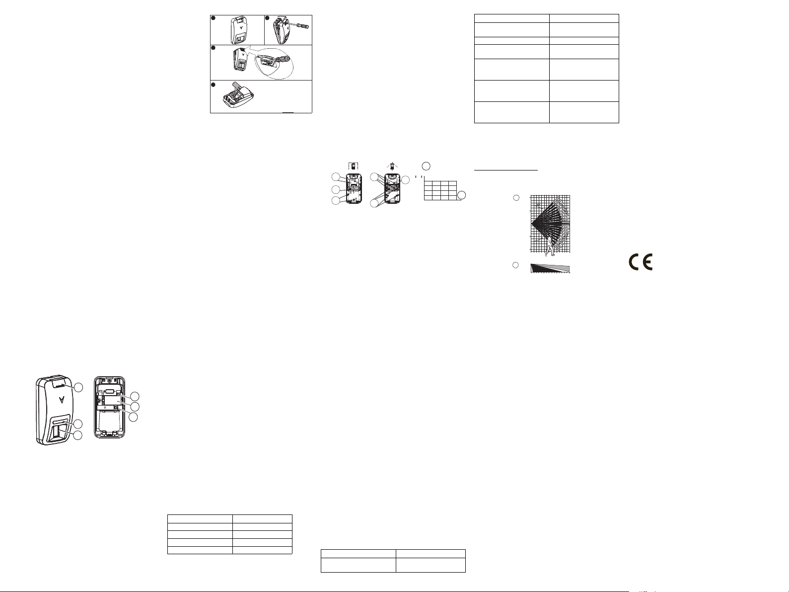
Legend
A. Screw cover
B. LED
C. PIR optical window
D. Enroll button (use a screwdriver to press the recessed but-
ton)
E. Battery
F. Tamper switch
G. Break-away base segment (shaded)
H. Mounting height
I. Coverage range
J. Horizontal view
K. Vertical view
X. Lower surface (with downward tilt)
Y. Upper surface (without downward tilt)
Installing the Battery
1 2
3
4
Caution! Risk of explosion if battery is replaced by an incorrect type. Dispose of used batteries according to the manufacturer's instructions and according to local rules and regulations.
Batteries are to be replaced by service persons only.
1. On the indicated location, lift the screw cover upward using
your thumb.
2. Release the screw and open the cover in the direction shown
by the arrow.
3. Insert a screwdriver into the slot and then push inward to separate the base from the cover.
4. Insert battery while observing polarity.
Note: When manually programming wireless devices, if a
device has been powered up for more than 48 hours it cannot be
enrolled into the system until the device has been tampered and
restored. When programming the panel using the Quick Enroll
procedure follow the steps detailed in Enroll the Device into the
System.
Note: After restoring a low battery trouble the system may take
up to 5 minutes to clear the trouble.
Enroll the Device into the System
To quick enroll:
1. On a keypad press [*] [8] [Installer Code] [804] [000].
2. Press and hold the device enroll button until the LED lights
steady and then release the enroll button while the LED is
still lit. A confirmation message then appears on the keypad.
3. Press [*] key to confirm ID.
4. Enter [3 digit zone #].
5. Enter [3 digit zone type].
6. Enter [1 digit partition #] for all desired partitions and press
[#]. If using an LCD keypad you can scroll to the desired partitions and press [*] to toggle the partition.
7. On an LCD keypad enter the label by using word library.
To pre-enroll:
1. Remotely configure the unique ID number into the system.
For more information see the HSM2HOST manual.
2. When on-site, press the device enroll button.
Note: If the wireless device has been powered for more than 48
hours without being enrolled, tamper and restore the device to
enroll it.
Perform a Placement Test
Before permanently mounting any wireless device, temporarily
mount the device and perform a Placement test.
1. Tamper the device by removing the cover.
2. Restore the tamper. The device now enters Placement test
mode for 15 minutes.
3. Trip the device and the red LED blinks once to identify that a
signal is being sent to the receiver and then blinks three times
to identify the signal strength. To perform a walk test, walk
across the far end of coverage pattern in both directions. The
following table indicates the received signal strength indication.
LED Response Signal Strength
Green LED blinks STRONG
Orange LED blinks GOOD
Red LED blinks POOR
No blinks No communication
IMPORTANT! Only GOOD or STRONG signal strengths are
acceptable. If you receive a POOR signal from the device, re-
locate it and re-test until a GOOD or STRONG signal is
received.
Note: For UL/ULC installations, only STRONG signal levels
are acceptable. After installation verify the product functionality in conjunction with the compatible receivers HSM2HOST9,
HS2LCDRF(P)9, HS2ICNRF(P)9 and PG9920.
Note: For detailed Placement instructions refer to the control
panel Reference Guide.
Note: Perform a walk test of the coverage area at least once a
year to ensure that the detector is working correctly.
Mounting
Note: Mount the detector so that its orientation is perpendicular
to the expected intrusion path. For the desired detector's range
and height, use mounting holes x or y, as specified in the table
below.
Note: To be installed by service persons in non-hazardous locations only.
Use the following as a guide for locating a suitable mounting
location:
• Keep away from heat sources.
• Do not expose to air drafts.
• Do not install outdoors.
• Avoid direct sunshine.
• Keep wiring away from power cables.
• Do not install behind partitions.
• Mount on solid stable surface.
H
Y
Y
G
x
Caution! The back tamper switch will not protect the unit
unless the break-away base segment is secured to the wall with
at least one screw.
x
ft m
10 3.0
G
X
X
X
X
9 2.7
X
Y
X
X
8 2.4
X
Y
Y
X
7 2.1
b
Y
Y
Y
6 1.8
15
309451260 ft
6
15 m
Configuration
To enter the wireless configuration section enter [804][000].
Device Toggles
[001][01]
Alarm LED - Default [Y]
Enables the devices LED to activate when an alarm
event occurs.
[001][04]
Supervision - Default [Y]
Enables supervision of the device.
Selections
[003]
Hightraffic Shutdown - Default [01]
Activating this feature helps conserve battery power
when the system is disarmed by configuring a reporting
timer. When motion is detected, the device transmits an
alarm to the receiver and will not report any further
events until the timer expires. Any motion detected
during the configured period will be reported once the
timer expires. No Delay causes the device to report an
alarm each time the detector is tripped.
[01] Detector Disabled (while disarmed)
[04] 15 second
delay
[07] 5m delay [08] 10m delay [09] 20m delay
[10] 60m delay
[016]
Event counter - Default [002]
Alarm activates after a configured number of events
have been detected.
Key in activities
001-255
[02] No Delay [03] 5 second
[05] 30 second
delay
delay
[06] 1m delay
Event Indications
LED Indications Event
Red LED blinks Stabilization (warm-up 120
Red LED ON 0.2 sec. Tamper open / close
Red on 2 sec. Intruder alarm
Yellow LED on AM detection – Diagnostic
Yellow LED blinks slowly
(0.2 sec. ON, 30 sec. OFF)
sec)
mode
AM detection – Normal
mode
LED Indications Event
Yellow and red LED blink
simultaneously (0.2 sec. ON
[both], 0.2 sec. OFF)
Yellow and red LED blink
simultaneously slowly (0.2
sec. ON [both], 30 sec. OFF)
Self-test failure – Diagnostic
mode
Self-test failure – Normal
mode
Specifications
GENERAL
Detector Type: Dual element low-noise pyroelectric sensor
Lens Data
No. of Beam Elements:18x3=54 far parabolic mirror seg-
ments
10m
J
32.8ft
5m
16.4ft
0
5m
16.4ft
10m
32.8ft
0
5
15 m
10
49.2 ft
32.8
16.4
2.1 m
K
(6.9 ft)
51015 m
16.4 32.8 49.2 f t
Max. Coverage: 15 m (49 ft) / 90°25 m (82 ft) x 2.5 m
I
Pet Immunity (only): Up to 38 kg (85 lb)
ELECTRICAL
Internal Battery: 3V Lithium battery, type CR-123A (option-
ally can be used type CR-17450)
Note: For UL installations use Gold Peak (GP) only. Use only
the above battery type.
Nominal Battery Capacity: 1450 mA/h ( 2400mA/h for
optional CR17450)
Low Battery Threshold: 2.45 V
Battery Life (for typical use): 7 years (not tested by UL/ULC)
FUNCTIONAL
True Motion Event Verification: 2 remote selections - 1
(OFF) or 2 (ON) motion events
Alarm Period: 2 seconds
WIRELESS
Frequency Band (MHz): CE Listed PG4974: 433MHz; CE/
EN listed PG8974: 868MHz; FCC/IC/UL/ULC listed PG9974:
912-919MHz
Communication Protocol: PowerG
Supervision: Signaling at 4-min. intervals
Tamper Alert: Reported when a tamper event occurs and in
any subsequent message, until the tamper switch is restored
MOUNTING
Height: 1.8 – 3.0 m (6 - 10 ft).
Installation Options: Surface or corner
ACCESSORIES
PGBRACKET-1: Surface mounted swivel bracket, adjustable
30° down and 45° left/45° right.
PGBRACKET-2: PGBRACKET-1 with a corner adapter
PGBRACKET-3: PGBRACKET-1 with a ceiling adapter
Note: UL did not evaluate the product with the use of brackets.
ENVIRONMENTAL
RFI Protection: >20 V/m up to 2000 MHz, excluding inband
frequencies
Temperature range: -10°C to +55°C (UL/ULC only verified
the range 0ºC-49ºC)
Relative Humidity: up to max. 93%RH, non-condensing
PHYSICAL
Size (H x W x D): 115 x 60 x 48 mm (4-1/2 x 2-5/16 x 1-15/
16”)
Weight (with battery): 90 g (3 oz).
Color: White
COMPATIBLE RECEIVERS
433MHz Band: HSM2HOST4; HS2LCDRF(P)4;HS2ICNRF(P)4; PG4920
868MHz Band: HSM2HOST8; HS2LCDRF(P)8; HS2ICNRF(P)8;PG8920
912-919MHz Band: HSM2HOST9; HS2LCDRF(P)9; HS2ICNRF(P)9; PG9920
Note: Only devices operating in band 912-919MHz are UL/
ULC listed.
UL/ULC Notes
Only model PG9974 operating in the frequency band 912919MHz is UL/ULC listed. The PG9974 has been listed by UL
for commercial and residential burglary applications and by
ULC for residential burglary applications in accordance with
the requirements in the Standards UL 639 and ULC-S306 for
Intrusion Detection Units.
For UL/ULC installations use these devices only in conjunction
with compatible DSC wireless receivers: HSM2HOST9,
HS2LCDRF(P)9, HS2ICNRF(P)9 and PG9920. After installation verify the product functionality in conjunction with the
compatible receiver used.
Europe: The PG8974 and PG4974 are compliant with the RTTE
requirements - Directive 1999/5/EC of the European Parliament
and of the Council of 9 March 1999. Model PG8974 certified by
DNV (DET NORSKE VERITAS) to the following standards:
EN50131-2-2, EN50131-1 GRADE 2, CLASS I I, EN50131-6 Type C. DNV (DET
NORSKE VERITAS) has certified only the 868 MHz variant of this product.
According to EN 50131-1:2006 and A1:2009, this equipment can be applied in
installed systems up to and including Security Grade 2, Environmental Class II.
UK: The PG8974 is suitable for use in systems installed to conform to
PD6662:2010 at Grade 2 and environmental class 2. BS8243 The Power G
peripheral devices have two- way communication functionality, providing
additional benefits as described in the technical brochure. This functionality has
not been tested to comply with the respective technical requirements and should
therefore be considered outside the scope of the product’s certification
FCC COMPLIANCE STATEMENT
WARNING! Changes or modifications to this unit not expressly approved by the
party responsible for compliance could void the user’s authority to operate the
equipment.
This device has been tested and found to comply with the limits for a Class B
digital device, pursuant to Part 15 of the FCC Rules. These limits are designed to
provide reasonable protection against harmful interference in residential
installations. This equipment generates uses and can radiate radio frequency
energy and, if not installed and used in accordance with the instructions, may
cause harmful interference to radio and television reception.
However, there is no guarantee that interference will not occur in a particular
installation. If this device does cause such interference, which can be verified by
turning the device off and on, the user is encouraged to eliminate the interference
by one or more of the following measures:
– Re-orient or re-locate the receiving antenna.
– Increase the distance between the device and the receiver.
– Connect the device to an outlet on a circuit different from the one that supplies
power to the receiver.
– Consult the dealer or an experienced radio/TV technician.
This equipment complies with FCC and IC RF radiation exposure limits set forth
for an uncontrolled environment.
This device complies with FCC Rules Part 15 and with Industry Canada licenceexempt RSS standard(s). Operation is subject to the following two conditions: (1)
This device may not cause harmful interference, and (2) this device must accept
any interference that may be received or that may cause undesired operation.
Le present appareil est conforme aux CNR d'Industrie Canada applicables aux
appareils radio exempts de licence. L'exploitation est autorisee aux deux
conditions suivantes :(1) l'appareil ne doit pas produire de brouillage, et (2)
l'utilisateur de l'appareil doit accepter tout brou illage radioelectrique subi, meme si
le brouillage est susceptible d'en compromettre le fonctionnement.
PG9974(P)/PG8974(P)/PG4974(P)
5
0
16.4
0
15 m
49.2 ft
10
32.8
5m
16.4ft
5m
16.4ft
10m
32.8ft
10m
32.8ft
J
2.1 m
(6.9 ft)
51015 m
16.4 32.8 49.2 f t
K
Instructions d'installation du détecteur à miroir
sans fil de haute sécurité PowerG avec fonction
anti-masque
Caractéristiques
Les PGx974(P) (insensible aux animaux) sont des détecteurs
numériques IPR à miroir, sans fil, commandés par microprocesseur, bidirectionnels qui incluent les fonctions suivantes :
• Les indicateurs de qualité de liaison intégrés réduisent les
temps d'installation en supprimant la nécessité de
l'installateur d'être physiquement à proximité de la centrale.
• La technologie anti-masque à infrarouge actif adaptative
qui fournit une protection sûre et évoluée contre les
tentatives de masquage intentionnel (Brevet en instance).
• Il contient un émetteur-récepteur entièrement supervisé
PowerG.
• Des miroirs noirs intégrés en attente de brevet pour une
immunité contre un éclairage blanc extrêmement intense.
• Une technologie à miroir elliptique/parabolique avancée
(brevetée).
• La technologie optique V-slot® (brevetée) contre le
vandalisme pour une robustesse améliorée et une très haute
fiabilité.
• Protection au ras du mur.
• Le PX974P fait la distinction entre des êtres humains et des
animaux d'un poids jusqu'à 18 kg (40 lb).
• L'algorithme True Motion Recognition™ avancé (breveté)
distingue entre un mouvement réel d'un intrus et toutes
autres perturbations qui sont en mesure de créer des fausses
alarmes.
• Aucun réglage vertical n'est nécessaire.
• Le compteur d'événement de mouvement détermine si 1 ou
2 événements de déplacement consécutifs déclenchent une
alarme.
• Fin automatique de l'essai de marche après 15 minutes.
• Correction de température contrôlée par microprocesseur.
• Une chambre étanche protège le système optique.
• Protection anti-sabotage arrière et avant.
• Autodiagnostic.
Réglage du dispositif
Remarque : Pour garantir le fonctionnement continu de tous
les dispositifs sans fil après avoir réalisé une réinitialisation aux
valeurs par défaut, un téléchargement général de toute la programmation sans fil par DLS est recommandé avant de réinitialiser le système. Après avoir complété la réinitialisation aux
valeurs par défaut du système, téléchargez la programmation
sans fil.
A
B
C
Légende
A. Couvercle à vis
B. Voyant
C. Fenêtre optique IPR
D. Bouton d'attribution (utiliser un tournevis pour agir sur le
bouton encastré)
E. Batterie
F. Contact anti-sabotage
G. Segment de la base amovible (rayé)
H. Hauteur de fixation
I. Plage de couverture
J. Vue horizontale
K. Vue verticale
X. Surface inférieure (avec inclinaison vers le bas)
Y. Surface
supérieu
re (sans
inclinais
on vers
le bas)
1 2
3
Installer
la pile
Attention!
Risque
d'explosion si
la pile n'est
pas du type
correct.
Éliminer les
piles usagées selon les recommandations du fabricant, les lois
et réglementations locales. Les piles doivent être remplacées
uniquement par un agent de service.
1. À l'emplacement indiqué, soulevez le couvercle à vis en utilisant votre pouce.
2. Libérez la vis et ouvrez le couvercle dans la direction
indiquée par la flèche.
3. Insérez un tournevis dans le logement puis poussez vers
l'intérieur pour détacher la base du couvercle.
4. Insérez la pile tout en respectant la polarité.
Remarque : Quand vous programmez manuellement les dispositifs sans fil, si un dispositif a été alimenté pendant plus de
48 heures, il ne peut pas être attribué dans le système tant que le
dispositif n'a pas été saboté et rétabli.
Remarque: Après la restauration d'un défaut de batterie faible,
le système peut prendre jusqu'à 5 minutes pour que la peine.
4
Attribuer le dispositif dans le système
Pour une attribution rapide :
1. Sur le pavé numérique, appuyez sur [*] [8] [Code de l'installateur] [804] [000].
2. Appuyez de façon prolongée sur le bouton d'attribution du
dispositif tant que le voyant lumineux reste allumé, puis relâchez le bouton d'attribution alors que le voyant lumineux est
encore allumé. Un message de confirmation apparaît alors
sur le pavé numérique.
3. Appuyez sur la touche [*] pour confirmer le ID.
4. Entrez le [n° de zone à 3 chiffres].
5. Entrez le [3 chiffres de type de zone].
6. Entrez le [n° de partition à 1 chiffre] pour toutes les partitions
souhaitées et appuyez sur [#]. Si vous utilisez un pavé
numérique à cristaux liquides LCD, vous pouvez faire défiler
les partitions souhaitées et appuyer sur [*] pour basculer la
partition.
7. Sur un pavé numérique LCD, entrez la référence en utilisant
la bibliothèque de mot.
Pour une attribution préalable :
1. Configurez à distance le numéro ID unique dans le système.
Pour plus d'informations, consultez le manuel HSM2HOST.
2. Sur site, appuyez sur le bouton d'attribution du dispositif.
D
E
F
Remarque : Si le dispositif sans fil a été alimenté pendant plus
de 48 heures sans être attribué, sabotez et rétablissez le dispositif pour l'attribuer.
Réalisation d'un test de positionnement
Avant de fixer de façon permanente un dispositif sans fil quelconque, montez-le temporairement et effectuez un test de positionnement.
1. Sabotez le dispositif en retirant le cache.
2. Rétablissez le système anti-sabotage. Le dispositif passe en
mode de test de positionnement pendant 15 minutes.
3. Coupez le dispositif. Le voyant lumineux rouge clignote une
fois pour indiquer qu'un signal est transmis au récepteur, puis
clignote trois fois pour fournir la force du signal. Pour
effectuer un essai de marche, déplacez-vous dans les
extrémités de la zone de couverture dans les deux directions.
Le tableau suivant fournit les informations de force du signal
reçu.
Réponse du voyant Force du signal
Le voyant vert clignote FORT
Le voyant orange clignote BON
Le voyant rouge clignote FAIBLE
Aucun clignotement Aucune communication
IMPORTANT ! Seules les forces de signal FORT ou BON
sont acceptables. Si vous recevez un signal FAIBLE du disposi-
tif, déplacez-le et testez-le à nouveau jusqu'à ce qu'un signal
BON ou FORT soit reçu.
Remarque : Pour les installations UL/ULC, seul un signal
FORT est acceptable. Après installation, vérifiez les fonctionnalités de l'appareil en association avec les récepteurs compatibles HSM2HOST9, HS2LCDRF(P)9, HS2ICNRF(P)9 et
PG9920.
Remarque : Pour des instructions détaillées sur le positionnement, consultez le guide de référence de la centrale.
Remarque : Réalisez un essai de marche de l'aire de couverture
au moins une fois par an pour garantir le bon fonctionnement
du détecteur.
Fixation
Remarque : Fixez le détecteur de sorte qu'il soit orienté per-
pendiculairement au chemin d'intrusion attendu. Pour la hauteur et la plage du détecteur souhaitée, utilisez les trous de
fixation x ou y, comme précisé dans le tableau.
Remarque : À faire installer par un agent de service dans des
zones non dangereuses uniquement.
Utilisez les indications suivantes comme guide pour trouver un
emplacement de fixation convenable :
H
Y
Y
G
x
• Tenir à l'écart de sources de chaleur.
• Ne pas exposer aux courants d'air.
• Ne pas installer en extérieur.
• Éviter l'exposition directe aux rayons du soleil.
• Éloigner le câblage des câbles électriques.
• Ne pas installer derrière une cloison.
• Fixer sur une surface solide et stable.
Attention ! Le contact anti-sabotage arrière ne protègera l'unité
que lorsque le segment de la base amovible sera fixé au mur
avec au moins une vis.
x
ft m
10 3.0
G
X
X
X
X
9 2.7
X
Y
X
X
8 2.4
X
Y
Y
X
7 2.1
b
Y
Y
Y
6 1.8
15
309451260 ft
6
15 m
Configuration
Pour accéder à la section de configuration sans fil, entrez la
commande [804][000].
Commutateurs du dispositif
[001][01]
Voyant d'alarme : Par défaut [O]
Active le voyant du dispositif pour qu'il s'allume en
cas d'alarme.
[001][04]
Supervision : Valeur par défaut [O]
Active la supervision
Sélections
[003]
Arrêt de trafic élevé : Par défaut [01]
L'activation de cette fonction vous permet d'économiser
la batterie quand le système est désarmé en lançant une
temporisation de notification. Quand un mouvement est
détecté, le dispositif transmet une alarme au récepteur et
ne signalera plus aucun autre événement tant que le temporisateur n'expire. Tout mouvement détecté pendant la
période configurée sera signalé une fois le temporisateur
expiré. L'absence de délai fait que le dispositif signale
une alarme chaque fois que le détecteur est déclenché.
[01] Désactivé
(alors désarmé)
[04] Retard de 15
secondes
[07] Retard de 5 m[08] Retard de 10 m[09] Retard de 20
[10] Retard de
60m
[016]
Compteur d'événement : Par défaut [002]
L'alarme s'enclenche lorsque le nombre défini d'événements est détecté.
Touche en activité
001-255
[02] Aucun retard [03] Retard de 5
[05] Retard de 30
secondes
secondes
[06] Retard de 1
m
m
Événements indiqués
Description des voyants Événement
Le voyant rouge clignote Stabilisation (préchauffage
de 120 s)
Description des voyants Événement
Voyant rouge allumé 0,2 s. Contact anti-sabotage
Rouge allumé 2 s. Alarme d'intrusion
Voyant jaune allumé Détection AM : Mode diag-
Le voyant jaune clignote lentement (0,2 s allumé,
30 s éteint)
Les voyants jaune et rouge
clignotent simultanément (0,2
s allumés, 0,2 s éteints)
Les voyants jaune et rouge
clignotent lentement
(0,2 s allumés, 30 s éteints)
ouvert/fermé
nostic
Détection AM : Mode normal
Problème d'autodiagnostic :
Mode diagnostic
Problème d'autodiagnostic :
Mode normal
Caractéristiques techniques
GÉNÉRALITÉS
Type de détecteur : Détecteur pyroélectrique à deux éléments,
faible bruit
Information sur la lentille
Nb. d'éléments de faisceaux : 18 x 3 = 54 segments de
miroir parabolique éloignés
I
Couverture max.: 15 m (49 pieds)/90° 25 m (82 pieds) x 2,5 m
Insensibilité aux animaux (uniquement) : 38 kg (85 lb) max.
DONNÉES ÉLECTRIQUES
Batterie interne : Batterie au lithium de 3 V, de type CR-123A
(utiliser éventuellement le type CR-17450)
Remarque : Pour les installations UL, utilisez exclusivement
des piles Gold Peak (GP). Utilisez exclusivement le type de pile
indiqué ci-dessus.
Capacité nominale de la batterie : 1450 mA/h (2400 mA/h
avec la pile CR17450)
Seuil de niveau faible de pile : 2,45 V
Autonomie de la batterie (usage type) : 7 ans (non vérifiés
par UL/ULC)
INFORMATIONS FONCTIONNELLES
Contrôle d'événement de mouvement réel : 2 sélections à
distance : 1 (DÉSACTIVÉ) ou 2 (ACTIVÉ) événement(s) de
mouvement
Durée d'alarme : 2 secondes
TRANSMISSION SANS FIL
Plage de fréquences (Mhz) : PG4974 homologué CE : 433
MHz ; PG8974 homologué CE/EN (Royaume-Uni) : 868 MHz
; PG9974 homologué FCC/IC/UL/ULC : 912-919 MHz
Protocole de communication : PowerG
Supervision : Signalisation par intervalles de 4 min.
Alarme de sabotage : Signalé quand un événement de sabo-
tage survient et dans tous les messages qui suivent, tant que le
contact anti-sabotage n'est pas rétabli.
FIXATION
Hauteur : de 1,8 à 3,0 m (de 6 à 10 pieds).
Options d'installation : En surface ou dans un angle.
ACCESSOIRES
PGBRACKET-1 : Support pivotable monté en surface, inclinable à 30° vers le bas et de 45° à droite/gauche.
PGBRACKET-2 : PGBRACKET-1 avec un adaptateur d'angle
PGBRACKET-3 : PGBRACKET-1 avec un adaptateur pour
plafond
Remarque : L'organisme UL n'a pas évalué le produit avec
l'utilisation des supports .
INFORMATIONS ENVIRONNEMENTALES
Protection RFI : > 20 V/m jusqu'à 2000 MHz, à l'exclusion
des fréquences dans la bande.
Plage de Température : de -10 °C à +55 °C (UL/ULC a
uniquement vérifié la plage est de 0 °C à 49 °C)
Taux d'humidité relative : Jusqu'à 93 % max., sans condensation
MESURES PHYSIQUES
Dimensions (H x l x P) : 115 x 60 x 48 mm (4-1/2 x 2-5/16 x 1-
15/16 po)
Poids (pile incluse) : 90 g (3 oz).
Couleur : Blanc
RÉCEPTEURS COMPATIBLES
Bande de 433 MHz : HSM2HOST4; HS2LCDRF(P)4; HS2ICNRF(P)4; PG4920
Bande de 868 MHz : HSM2HOST8; HS2LCDRF(P)8; HS2ICNRF(P)8; PG8920
Bande de 912-919 MHz : HSM2HOST9; HS2LCDRF(P)9;
HS2ICNRF(P)9; PG9920
Remarque : Seuls les dispositifs fonctionnant dans la bande
912-919 MHz sont référencés UL/ULC.
Remarques UL/ULC
Seul le modèle PG9974 fonctionnant dans la bande de
fréquences 912-919 MHz est homologué UL/ULC. Le PG9974
est homologué UL pour les applications commerciales et résidentielles anti-intrusion et homologué ULC pour les applications résidentielles anti-intrusion conformément à la
réglementation des normes UL 639 et ULC-S306 pour les
unités de détection d'intrusion.
Pour les installations UL/ULC, utilisez uniquement ces dispositifs en association avec des récepteurs sans fil DSC compatibles
: HSM2HOST9, HS2LCDRF(P)9, HS2ICNRF(P)9 et PG9920.
Après installation, vérifiez les fonctionnalités du produit en
association avec le du récepteur compatible utilisé.
Europe : Le PG8974 est la PG4974 sont compatible avec la
réglementation RTTE : directive 1995/5/EC du Parlement
Européen et du Conseil du 9 mars 1999. PG8974 certifié par DNV
(DET NORSKE VERITAS) pour les normes suivantes : EN501312-2, EN50131-1 GRADE 2, CLASSE II, EN50131-6 Type C. DNV (DET
NORSKE VERITAS) a certifié uniquement les variantes à 868 MHz de ce
produit. Selon les normes EN 50131-1:2006 et A1:2009, cet équipement peut être
intégré dans les systèmes installés jusqu'à et y compris la classe environnementale
II, niveau de sécurité 2. Royaume-Uni : Le PG8974 co nvient pour l'utilisation dans
les systèmes installés pour se conformer à la norme PD6662:2010 à la classe
environnementale 2 et de niveau de sécurité 2. Les dispositifs périphériques Power
G BS8243 sont dotés d'une fonction de communication bidirectionnelle, offrant
des avantages supplémentaires comme décrit dans la brochure technique. Cette
fonction n'a pas été déclarée conforme aux besoins techniques respectifs et doit,
par conséquent, être exclue de la certification du produi t.
PG9974(P)/PG8974(P)/PG4974(P)
Detector de espejo de alta seguridad inalámbrico
PowerG con instrucciones de instalación de
antibloqueo
Características
Los modelos PGx974(P) (inmunes a mascotas) son detectores
PIR de espejo digital, inalámbricos, bidireccionales y controlados por microprocesador, que incluyen las siguientes características:
• Los indicadores de calidad de enlace incorporados reducen
el tiempo de instalación al eliminar la necesidad del
instalador de acercarse físicamente al panel de control.
• Tecnología adaptable activa de antibloqueo infrarroja que
proporciona la protección confiable más avanzada contra
intentos intencionales de bloqueo (patente pendiente).
• Incluye un transmisor-receptor completamente supervisado
de PowerG.
• Incorpora espejos negros de patente pendiente para
inmunidad extremadamente alta a la luz blanca.
• Tecnología avanzada de espejo elíptico/parabólico
(patentada).
• Tecnología óptica V-slot® (patentada) para mayor robustez,
resistencia al vandalismo y una confiabilidad muy alta.
• Protección de zona de arrastre.
• El PGx974P puede distinguir entre seres humanos y
mascotas que pesan hasta 18 kg (40 lb).
• El avanzado algoritmo (patentado) de True Motion
Recognition™ distingue entre el movimiento verdadero de
 Loading...