

DSC PC6216 Installation Instructions Manual
PC6216
Output Module Installation Instructions
1. Introduction
The PC6216 is an output module with 16 programmable outputs.
2. Specifications
• 16 output low current module, 12V, 50mA max. each,
power drawn from Combus
• Up to 9 modules per system
• 9 modules programmable as alarm or zone annunciators
• Each of the 9 modules programmable for all 16 outputs;
available output options determined by the control panel
software version
• Connects to control panel via 4-wire Combus
• Nominal current draw of 30mA
• Tamper contact input
Compatible Cabinets
• PC4003C
• PC4006C
• PC4001C/4002C
3. Installing the PC6216
3.1 Unpacking
The PC6216 package should include the following parts:
• One PC6216 circuit board
• 4 plastic stand-offs
3. Press the circuit board into the plastic stand-offs to secure
the module to the cabinet.
Once the unit is mounted, wiring may be completed.
3.3 Installation and Wiring
Before beginning to wire the unit, ensure that all power (AC
transformer and battery) is disconnected from the control panel.
Perform the following steps to complete wiring:
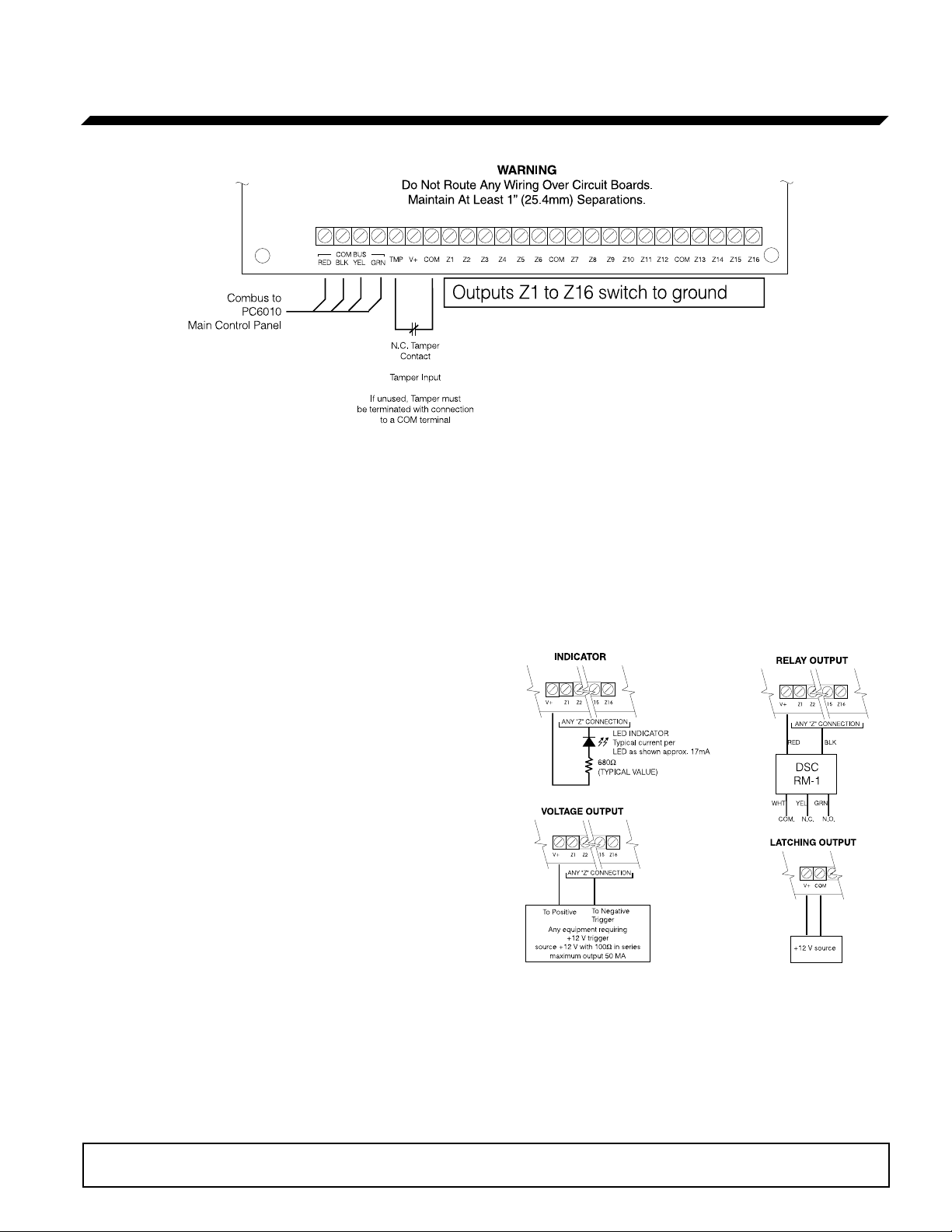
1. Connect the four Combus wires to the PC6216. Connect
the red, black, yellow and green Combus wires to the RED,
BLK, YEL and GRN terminals, respectively.
2. Complete all output wiring as illustrated below:
3.2 Mounting
The PC6216 should be located inside a compatible cabinet,
mounted in a dry, secure location. Preferably, it should be
placed at a convenient distance from the connected devices.
Perform the following steps to mount the unit:
1. Press the four plastic stand-offs through the mounting
holes at back of the cabinet.
2. Secure the cabinet to the wall in the desired location. Use
appropriate wall anchors when securing the cabinet to
drywall, plaster, concrete, brick or other surfaces.
The latching output will cause the status of all 16
programmable outputs to latch during a Combus reset. To
do this, connect as shown above.
3. Connect the external tamper switch, if used.
Consult the wiring diagrams for further information.
Please refer to the System Installation Manual for information on limitations regarding product
use and function and information on the limitations as to liability of the manufacturer.

3.4 Applying Power
After all wiring is completed, apply power to the control panel.
Connect the battery leads to the battery, then connect the AC
transformer. For more information on control panel power
specifications, see the control panel System Manual.
NOTE: Do not connect the power until all wiring is complete.
4. Enrolling and Programming the PC6216
Follow the instructions below for enrolling and programming
your PC6216 module. Refer to your System or Programming
manual for more information on programming.
NOTE: By default, before you can enroll modules, or change
any system programming, a user must tell the system to
“Allow System Service”. The system will then allow access to
Installer’s Programming for 60 minutes. Any user with a
Master code can tell the system to allow service at a system
keypad. The default Master code is [1234].
See the Maintenance Manual for more information. See the
Programming Manual – “Download Section” for more
information on the “User Allows Serv” toggle option.
4.1 Enrolling
You must enroll the PC6216 module with the panel before you
can program it. After you enroll the module, the system will
ask if you want to enable lamp testing on the module. See
section 4.3 for a description of the lamp test feature.
Follow these steps to enroll the module(s):
1 At a PC6010 system LCD keypad, enter Installer’s
Programming ([*][8][Installer’s code]).
2 Scroll to Module Hardware, press [*], then, scroll to
Enroll Module, press [*].
3 Scroll to PC6216 16 O/P, press [*].
4 The LCD keypad displays Create Tamper on Desired Unit.
Tamper and then restore the PC6216 module:
a) open and close the tamper switch, if one is installed on
the module OR
b) momentarily disconnect the jumper wire between the
TMP and COM terminals.
The LCD keypad displays PC6216 (nn) Enrolled where (nn)
is the number of the PC6216 module.
5 Record the number of the PC6216 module in the
programming worksheet, opposite.
6 Press any key. The keypad displays Lamp Test Y/N. Press
[*] to toggle between yes and no. To exit, press [#].
7 To exit module enrollment, press [#].
NOTE: If you need to change the Lamp Test option on a
PC6216 module after it has been enrolled, you must delete
and then re-enroll the module.
4.2 Programming
Program the PC6216 module to follow one of 9 custom
groups.
A custom group is a set of 16 programming choices that
correspond to the 16 programmable outputs on each PC6216
module. Example: a PC6216 is assigned to custom group (01),
in which output (05) is programmed as output option (18),
zone follow, for zone (020), which is a fire zone. LED 5 turns
on when zone (020) is in alarm and turns off when zone (020)
is restored and a fire reset is performed. If you assign a
PC6216 module to a custom group, you must also assign an
output option to each programmable output in the group.
More than one module may follow the same custom group.
Assign a Custom Group
1. Scroll to System Area, press [*], PGM Outputs, press [*],
then 4216 Options, press [*].
2. Scroll through the list of PC6216 modules to choose the
one you want to program (01-09). Press [*].
3. Scroll through the available options to choose a custom
group. Press [*] to select.
4. To exit, press [#].
Program a Custom Group
If you have assigned a PC6216 module to a custom group, you
need to program the 16 outputs in the group.
1. Scroll to System Area, press [*], PGM Outputs, press [*],
then 4216 Custom, press [*].
2. Scroll to the custom group you want to program (01-09).
Press [*].
3. Enter the number of the output to be programmed (01-16).
4. Enter the number of the output option to be used for that
output. Refer to your system’s Programming manual for
descriptions of the available programmable output options.
5. To exit, press [#].
4.3 Testing the PC6216
If you have enabled the lamp test option on the PC6216
module, master users will be able to conduct a lamp test.
• The LEDs on the PC6216 modules with the lamp test
option enabled turn on for 2 seconds.
Refer to the Maintenance Manual for instructions.
 Loading...