

Page 1
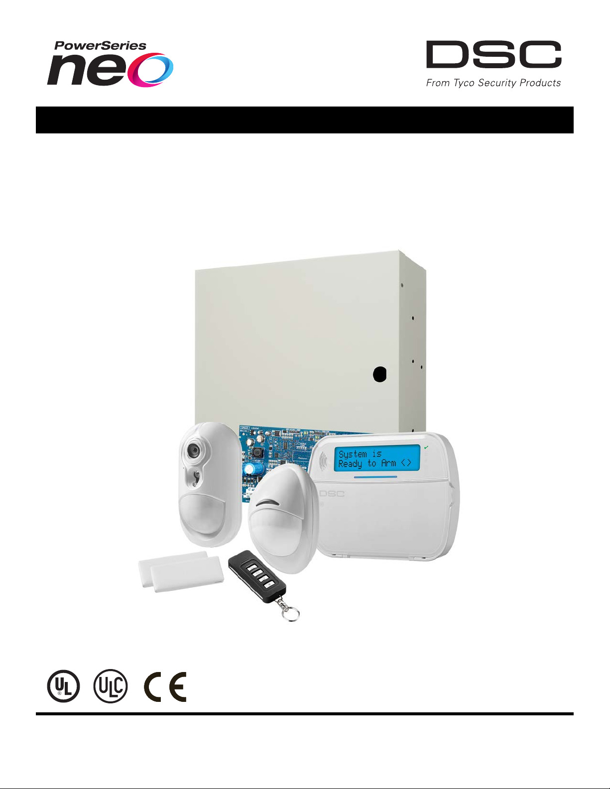
PowerSeries Neo Alarm Controller
V1.1 Reference Manual
Models:
HS2016-4/HS2016/HS2032/HS2064/HS2128
WARNING: This manual contains information on limitations regarding product use and function and information on the limitations
as to liability of the manufacturer. The entire manual should be carefully read.
Page 2

Safety Instructions for Service Personnel
Warning: When using equipment connected to the telephone network, always follow the basic safety instructions provided
with this product. Save these instructions for future reference. Inform the end-user of the safety precautions that must be
observed when operating this equipment.
Before Installing The Equipment
Ensure your package includes the following items:
l Installation and User manuals, including the SAFETY INSTRUCTIONS.
READ and SAVE these instructions!
Follow all WARNINGS AND INSTRUCTIONS specified within this document and/or on the equipment.
l HS2016-4/HS2016/2032/2064/2128 alarm controller
l Power Supply, direct plug-in
l Mounting hardware
Selecting A Suitable Location For The Alarm Controller
Use the following list as a guide to find a suitable location to install this equipment:
l Locate near a telephone socket and power outlet.
l Select a location free from vibration and shock.
l Place alarm controller on a flat, stable surface and follow the installation instructions.
Do NOT locate this product where people may walk on the secondary circuit cable(s).
Do NOT connect alarm controller to electrical the same circuit as large appliances.
Do NOT select a location that exposes your alarm controller to direct sunlight, excessive heat, moisture, vapors, chemicals or
dust.
Do NOT install this equipment near water. (e.g., bath tub, kitchen/laundry sink, wet basement, near a swimming pool).
Do NOT install this equipment and accessories in areas where risk of explosion exists.
Do NOT connect this equipment to electrical outlets controlled by wall switches or automatic timers.
AVOID interference sources.
AVOID installing equipment near heaters, air conditioners, ventilators, and refrigerators.
AVOID locating equipment close to or on top of large metal objects (e.g., wall studs).
See "Locating Detectors and Escape Plan" on page 221 for information on locating smoke and CO detectors.
SAFETY Precautions Required During Installation
l NEVER install this equipment and/or telephone wiring during a lightning storm.
l NEVER touch uninsulated telephone wires or terminals unless the telephone line has been disconnected at the net-
work interface.
l Position cables so that accidents can not occur. Connected cables must NOT be subject to excessive mechanical
strain.
l Use only the power supply provided with this equipment. Use of unauthorized power supplies may cause damage.
l For direct plug-in versions, use the transformer supplied with the device.
WARNING: THIS EQUIPMENT HAS NO MAINS ON/OFF SWITCH. THE PLUG OF THE DIRECT PLUG-IN POWER SUPPLY
IS INTENDED TO SERVE AS THE DISCONNECTING DEVICE IF THE EQUIPMENT MUST BE QUICKLY DISCONNECTED.
IT IS IMPERATIVE THAT ACCESS TO THE MAINS PLUG AND ASSOCIATED MAINS SOCKET/OUTLET IS NEVER
OBSTRUCTED.
IMPORTANT NOTE FORNORTHAMERICA!
This alarm system must be installed and used within an environment that provides the pollution degree max 2 and overvoltages category II NON- HAZARDOUS LOCATIONS, indoor only. The equipment is DIRECT PLUG- IN (external
transformer) and is designed to be installed, serviced and/or repaired by service persons only; [service person is defined as
a person having the appropriate technical training and experience necessary to be aware of hazards to which that person
may be exposed in performing a task and of measures to minimize the risks to that person or other persons]. This equipment
has no mains on/off switch; if the equipment must be quickly disconnected, the plug of the direct plug-in power supply is
intended to serve as the disconnecting device; it is imperative that access to the mains plug and associated mains
socket/outlet, is never obstructed. There are no parts replaceable by the end-user within this equipment. The wiring (cables)
- 2 -
Page 3

used for installation of the alarm system and accessories, shall be insulated with PVC, TFE, PTFE, FEP, Neoprene or
Polyamide.
(a) The equipment enclosure must be secured to the building structure before operation.
(b) Internal wiring must be routed in a manner that prevents:
- Excessive strain or loosening of wire on terminal connections;
- Damage of conductor insulation
(c) Disposal of used batteries must be made in accordance with local waste recovery and recycling regulations.
(d) Before servicing, DISCONNECT the power and telephone connection.
(e) DO NOT route any wiring over circuit boards.
(f) The installer is responsible to ensure that a readily accessible disconnect device is incorporated in the building for
permanently connected installations.
The power supply must be Class II, FAIL SAFE with double or reinforced insulation between the PRIMARY and
SECONDARY CIRCUIT/ENCLOSURE and be an approved type acceptable to the local authorities. All national wiring rules
must be observed.
IMPORTANT NOTE FORINTERNATIONALMARKET (EU, AUS, NZ, etc.)!
This equipment is stationary- fixed and must be installed by Service Persons only (Service Person is defined as a person
having the appropriate technical training and experience necessary to be aware of hazards to which that person may be
exposed in performing a task and of measures to minimize the risks to that person or other persons). It must be installed and
used within an environment that provides the pollution degree max 2, over voltages category II, in non- hazardous, indoor
locations only.
When using equipment connected to the mains and/or to the telecommunication network, there are basic safety instructions
that should always be followed. Refer to the safety instructions provided with this product and save them for future reference.
To reduce the risk of fire, electric shock and/or injury, observe the following:
Do not attempt to service this product yourself. Opening or removing the cover may expose you to dangerous voltage or
other risk. Refer servicing to qualified service persons. Never open the device yourself. Use authorized accessories only
with this equipment. DO NOT leave and/or deposit ANY object on the top of the cabinet of this equipment! The cabinet as it is
installed on the wall is not designed to support any supplementary weight! Do not spill any liquids on the cabinet. Do not
touch the equipment and its connected cables during an electrical storm; there may be a risk of electric shock. Never touch
uninsulated wires or terminals unless the equipment has been disconnected from the mains supply and from the
telecommunication network! Ensure that cables are positioned so that accidents cannot occur. Connected cables must not
be subject to excessive mechanical strain. Do not spill any type of liquid on the equipment. Do not use the Alarm system to
report a gas leak if the system is near a leak. Do not subject the connected cables to an excessive mechanical strain.
These safety instructions should not prevent you from contacting the distributor and/or the manufacturer to obtain any further
clarification and/or answers to your concerns.
- 3 -
Page 4

Contents
Section 1: Introduction 7
1.1 About the System 7
Section 2: Installation 12
2.1 Overview of Installation Process 12
2.2 Alarm Controller Installation 12
2.3 Wiring 13
2.4 Installing Modules 18
Section 3: Configuration 29
3.1 Basic Configuration Steps 29
3.2 Using the Keypad 29
3.3 Enrollment 30
3.4 Working with Partitions 32
3.5 Trouble Indicators 33
3.6 Keypad Partition Setup 33
3.7 Alternate Communicator Setup 35
3.8 Local Firmware Upgrade 36
3.9 Testing the System 36
Section 4: System Operation 37
4.1 Arming and Disarming 37
4.2 Partition vs. Global Keypad 37
4.3 Labels 38
4.4 Annunciation 39
4.5 Keypad Function Keys 39
4.6 Language Selection 42
4.7 [*] Commands 42
4.8 SMS Command and Control 55
4.9 Visual Verification 56
Section 5: Programming 57
5.1 How to Program 57
5.2 Programming Methods 57
5.3 Programming Descriptions 61
Section 6: Programming Worksheets 122
6.1 Label Programming 122
6.2 Zone Setup 127
6.3 System Times 130
6.4 Access Codes 132
6.5 PGM Programming 132
6.6 System Lockout 145
6.7 System Options 145
6.8 Auto-Arm/Disarm 150
6.9 Partition and Zone Assignment 154
6.10 Communications 156
6.11 DLS Programming 166
- 4 -
Page 5

6.12 Virtual Inputs 166
6.13 Schedule Programming 167
6.14 Audio Module Programming 172
6.15 Wireless Programming 177
6.16 Alternative Communicators 178
6.17 Keypad Programming 178
6.18 Template Programming 180
6.19 System Information and Testing 180
6.20 Module Programming 181
6.21 Testing 182
6.22 Battery Settings 182
6.23 Restoring Factory Defaults 183
Section 7: Troubleshooting 184
7.1 Testing 184
7.2 Troubleshooting 184
Appendix 1: Reporting Codes 192
Appendix 2: Word Library 201
Appendix 3: Template Programming Tables 202
Appendix 4: Regulatory Approvals 208
Appendix 5: ASCII Characters 215
Appendix 6: Wiring Diagrams 216
Appendix 7: Specifications 219
8.0 Index 229
- 5 -
Page 6

Page 7

Section 1: Introduction
CP-01
EN
NFA2P
UK
1.1 About the System
The PowerSeries Neo alarm panel is a feature-rich, scalable alarm system designed for residential and light commercial
use. The alarm panel supports both hardwired and wireless devices. This section lists the features of the alarm panel, available models, and compatible devices.
The following symbols are used to indicate features or methods of operation that are only available in a particular market. No
symbol indicates the feature or operation is available for all markets unless noted specifically otherwise.
- North America
- Europe
- France
- United Kingdom
1.1.1 Features
The following features are available on the PowerSeries Neo alarm controller.
Zones, Wireless Keypads, Wireless Keys, Panic Pendents and Proximity Tags
l 16, 32, 64, or 128 wireless or hardwired zones supported, including 6 or 8 hardwired zones available on the con-
troller.
l 40 zone types and 14 programmable zone attributes
l Up to 16 separate wireless keypads supported
l Up to 32 separate wireless keys or supported
l Up to 94 separate proximity tags supported
Access Codes
l Up to 97 access codes: 94 (level 2-EN) one system master code (level 3-EN), one installer code (level 3-EN), and
one maintenance code
l Programmable attributes for each user code ("Access Code Attributes" on page 49)
Programmable Outputs (PGMs)
l Up to 4 programmable outputs (PGM) on the alarm controller with 49 available options
l 22, 38, 80, 148 maximum programmable outputs
System Supervision Features
The PowerSeries Neo continuously monitors a number of possible trouble conditions and provides audible and visual indication at the keypad. Trouble conditions include:
l AC power failure
l Zone trouble
l Fire trouble
l Telephone line trouble
l Communicator trouble
l Low battery condition
l RF jam
l AUX power supply fault
l Failure to communicate
l Module fault (supervisory or tamper)
Additional Features
l 2-way wireless device support
l Visual verification (images + audio)
l Proximity tag support
l PGM scheduling
l Quick arming
- 7 -
Page 8

Section 1: Introduction
l User, partition, module, zone and system labels
l Programmable system loop response
l Keypad and panel software versions viewable through keypad
l Doorbell zone type
l Low battery PGM type
1.1.2 Available Models
The following alarm controller models are available:
l HS2016-4
l HS2016
l HS2032
l HS2064
l HS2128
Note: Not all models are available in all markets.
Model Differences
The table below lists the features of each alarm system model.
Table 1-1 Model Differences
Features HS2128 HS2064 HS2032 HS2016 HS2016-4
Hardwired zones 128 64 32 16 16
Onboard zone inputs 8 8 8 6 8
Wireless zones 128 64 32 16 32
Partitions 8 8 4 2 8
Users 95 95 72 48 48
Onboard outputs 4 4 2 2 4
Max outputs 148 80 38 22 24
Keypads 16 8 8 8 8
Wireless keys 32 32 32 16 16
Wireless sirens 16 8 8 4 4
Wireless repeaters * 8 8 8 4 4
Proximity tags 94 94 71 47 47
Alt Comm. phone #’s 4 4 4 4 4
User-programmable phone #’s 8 8 8 8 8
Event buffer 1000 500 500 500 500
8-zone expander HSM2108 15 7 3 1 1
Power supply HSM2300 4 3 3 3 3
Power supply/high-current output expander
HSM2204
8-output expander HSM2208 16 8 4 2 2
2- way wireless integration module 1 1 1 1 1
Audio verification module HSM2955 1 1 1 1 1
4 3 1 1 1
*For UL installations, 2 repeaters must be installed for proper signal routing.
- 8 -
Page 9

Section 1: Introduction
1.1.3 Compatible Devices
The following wireless devices and modules are compatible with this alarm controller.
Note: On the table below and throughout this document, x in the model number represents the operating frequency of the
device as follows: 9 (912-919 MHz), 8 (868MHz), 4 (433MHz).
Note: Only models operating in the band 912-919 MHz are UL/ULC listed where indicated. OnlyULapproved devices are to
be used with UL/ULC listed systems.
Table 1-2 Compatible Devices
Modules
Wireless keypads HS2LCDWFx
HS2LCDWFPx
HS2LCDWFPVx
Hardwired keypads with 2-way wireless integration module HS2LCDRFx
HS2LCDRFPx
HS2ICNRFx
HS2ICNRFPx
Hardwired keypads HS2LCD
HS2LCDP
HS2ICN
HS2ICNP
HS2LED
Touchscreen Keypad
HS2TCHP
Note: For ULC-s559 Listed applications the HS2TCHP touch screen keypad is for supplementary use
only.
2-way wireless integration module HSM2HOSTx
8-zone expander HSM2108
8-output expander HSM2208
Power supply HSM2300
4 high current output expander HSM2204
Alternate communicator 3G2080
3G2080R
TL280
TL280R
TL2803G
TL2803GR
PCL-422
UL
UL
UL
UL
UL
UL
UL
UL
UL
UL
UL
UL
UL
UL
UL
UL
UL
UL
UL
UL
UL
UL
- 9 -
Page 10

Section 1: Introduction
Hardwired Devices
2-wire smoke detector
FSA-210y
FSA-210yT
y= A, B, or C
FSA-210yS
FSA-210yST
A: ULC listed models
B: UL listed models
C: European and Australian models
FSA-210yR
FSA-210yRT
FSA-210yRS
FSA-210yRST
4-wire smoke detector
FSA-410y
FSA-410yT
x= A, B, or C
FSA-410yS
FSA-410yST
A: ULC listed models
B: UL listed models
C: European and Australian models
FSA-410yR
FSA-410yRT
FSA-410yRS
FSA-410yRST
CO detector CO-12/24
12-24SIR
FW-CO12
FW-CO1224
CO1224
UL
UL
UL
UL
UL
UL
UL
UL
UL
UL
UL
UL
UL
UL
UL
UL
UL
UL
UL
UL
UL
Wireless Devices
Wireless PG smoke detector PGx926
Wireless PG smoke and heat detector PGx916
Wireless PG CO detector PGx913
Wireless PG PIR motion detector PGx904(P)
Wireless PG PIR + camera motion detector PGx934(P)
Wireless PG curtain motion detector PGx924
UL
UL
UL
UL
UL
UL
Wireless PG dual tech motion detector PGx984(P)
Wireless PG mirror motion detector PGx974(P)
Wireless PG outdoor motion detector PGx994
UL
UL
Wireless PG glass break detector PGx912
Wireless PG shock detector PGx935
Wireless PG flood detector PGx985
Wireless PG temperature detector (indoor use) PGx905
UL
UL
UL
Outdoor temperature probe (requires PGx905) PGTEMP-PROBE
Wireless PG key PGx939
Wireless PG key PGx929
Wireless PG panic key PGx938
Wireless PG 2-button key PGx949
Wireless PG indoor siren PGx901
UL
UL
UL
UL
UL
- 10 -
Page 11

Section 1: Introduction
Wireless PG outdoor siren PGx911
Wireless PG repeater PGx920
Wireless PG door/window contact PGx975
Wireless PG door/window contact w/ AUX PGx945
UL
UL
UL
UL
Central Station Receivers
SG-System I, II, III, IV, 5
Enclosures
The HS2128/HS2064/HS2032/HS2016 main board can be installed in the metal enclosures listed below: Tamper
protection switches can be installed on all enclosures, including door opening protection and/or removal from the mounting
position. Doors can be secured using screws or keylock.
• Model PC5003C (removable door) made of 22Ga steel, painted, dimensions: 248mm(L) x 298mm(W) x 76mm(H), weight:
4.5Kg (with PCB, 7AH battery and transformer included)
• Model Power UC1 made of 18Ga steel, painted, dimensions: 315mm(L) x 319mm(W) x 100mm(H), weight: 6.15Kg (with
PCB, 7AH battery and transformer included).
....
For EN50131-1 Grade 2 compliant installations, all holes on the side of the cabinets shall be covered (plugged) if no
accessories are installed in the cabinet that will use these mounting holes.
The equipment enclosure shall be secured to the building structure before operation. Use 4 screws (appropriate for the wall
material on which it is attached) inserted through the four mounting holes provided in the back of the enclosure base.
- 11 -
Page 12

Section 2: Installation
2.1 Overview of Installation Process
The steps below are provided to assist with the installation of the alarm system. Read over this section to get an overall
understanding of the order of installation. Working from this plan can help reduce problems and reduce the overall time
required for installation.
Step 1 – Create a Layout
Draw a rough sketch of the site and include all alarm detection devices, zone expanders, keypads and other required modules.
Step 2 – Mount the Panel
Decide on a location for the alarm panel and secure it to the wall using suitable mounting hardware. See "Mounting the
Enclosure" on page 12.
Step 3 – Wire the Alarm Controller
Wire each of the modules to the alarm controller following the guidelines provided in section "Corbus Wiring" on page 15.
Step 4 – Wire Zones
Complete all zone wiring. Follow the guidelines provided in section "Zone Wiring" on page 21 to connect zones using normally closed loops, single EOL resistor, double EOL resistors, fire zones and keyswitch arming zones.
Step 5 – Complete Wiring
Complete all other wiring including bells or sirens, telephone line connections, ground connections or any other wiring
necessary. Follow the guidelines provided in section "Terminal Descriptions" on page 13.
Step 6 – Power up the Control Panel
Once all zone and alarm controller wiring is complete, connect the battery before applying AC, and power up the system.
The alarm controller will not power up if only the battery is connected.
Step 7 – Enroll Keypads and Modules
All keypads must be enrolled in order to operate on the system. To enroll the first keypad, see "Enrolling the First Keypad "
on page 31. To enroll optional keypads, enter installer's programming section [902][000]. For more information, see "Module
Programming" on page 117.
Step 8 – Confirm Module Supervision
By default, all modules are supervised upon installation. Supervision is enabled at all times. To confirm that each module is
properly supervised, see "[903] Confirm Module" on page 118.
Step 9 – Enroll Wireless Devices
Wireless devices are enrolled via the wireless transceiver module (HSM2HOSTx) or RF keypad and Installer Programming
section [804]. See "Wireless Programming" on page 116 to enroll wireless devices.
Step 10 – Program the System
Section 5 on "Programming" on page 57 provides a complete description of how to program the alarm controller. It contains
complete descriptions of the various programmable features and options. Fill out the programming worksheets starting at
"Programming Worksheets" on page 122 completely before attempting to program the system.
Step 11 – Test the System
Test the panel completely to ensure that all features and functions operate as programmed.
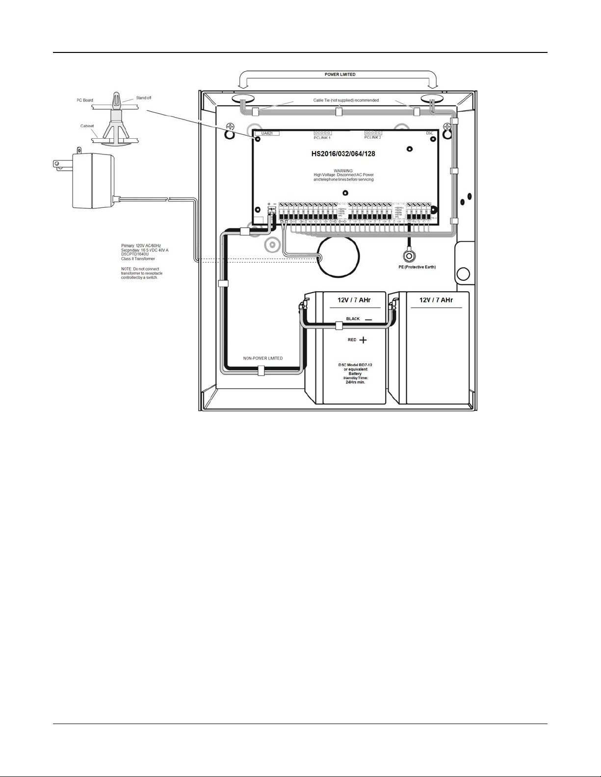
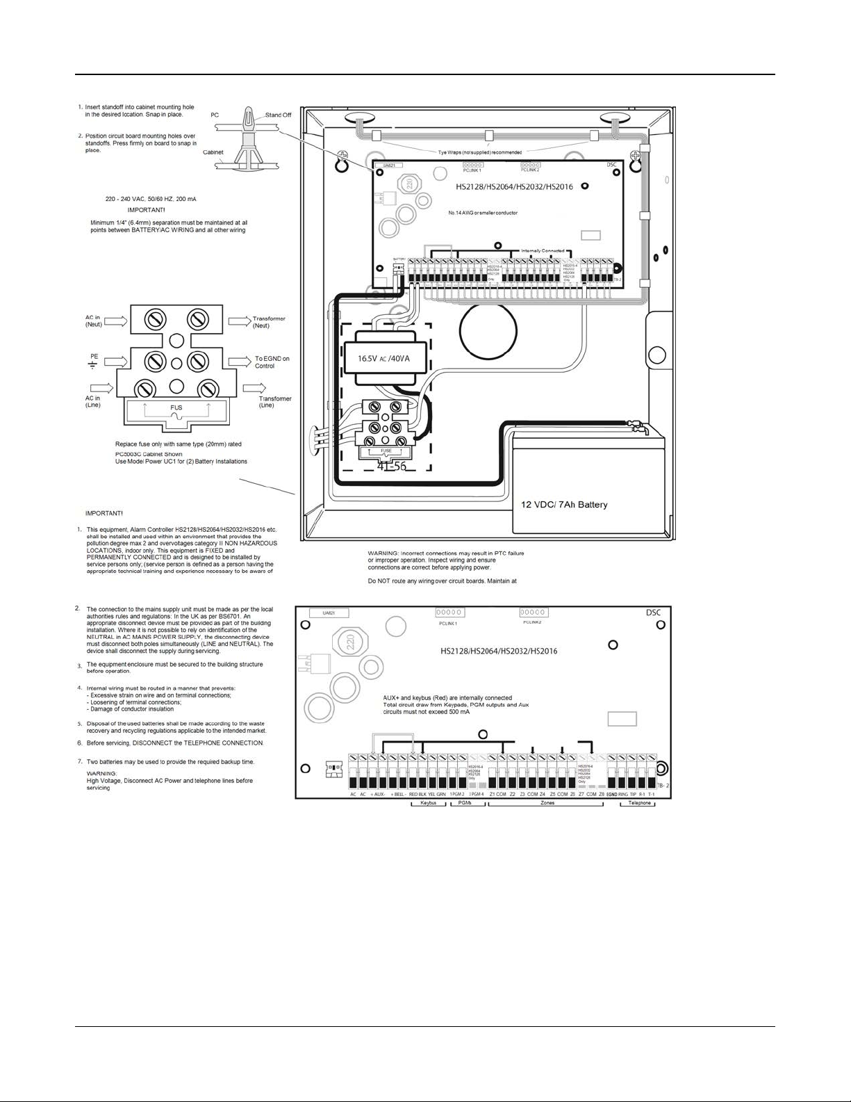
2.2 Alarm Controller Installation
Begin the installation by mounting the alarm controller in the metal enclosure using the stand-offs provided. Optional modules, such as the HSM2108 and HSM2208, can also be mounted in the enclosure.
Install hardware in the sequence indicated on the following pages.
2.2.1 Mounting the Enclosure
Locate the panel in a dry area, preferably near an unswitched AC power source and the incoming telephone line. Complete
all wiring before applying AC or connecting the battery.
- 12 -
Page 13

Section 2: Installation
2.3 Wiring
All wiring entry points on the enclosure are designated by arrows. All circuits are classified UL power limited except for the
battery leads. Minimum 1/4” (6.4mm) separation must be maintained at all points between power limited and non-power limited wiring and connections.
2.3.1 Terminal Descriptions
The following terminals are available on the PowerSeries Neo alarm controller.
Terminal Description
BAT+, BAT- Battery terminals. Use to provide backup power and additional current when system demands exceed the
power output of the transformer, such as when the system is in alarm.
Do not connect the battery until all other wiring is complete.
AC Power terminals.
Connect the battery before connecting the AC. Do not connect the battery or transformer until all other wiring
is complete.
AUX+, AUX- Auxiliary terminals. Use to power modules, detectors, relays, LEDs, etc. (700mA MAX). Connect the positive
side of device to AUX+, the negative side to AUX-.
BELL+,
BELL-
RED, BLK,
YEL, GRN
PGM1 to
PGM4
Z1 to Z8
COM
EGND Earth ground connection.
TIP, RING,
T-1, R-1
PCLINK_1 DLS/SA
PCLINK_2 DLS/SA, Alternate Communicator
Bell/Siren power (700mA MAX). Connect the positive side of any alarm warning device to BELL+, the
negative side to BELL-.
Corbus terminals. Use to provide communication between the alarm controller and connected modules. Each
module has four Corbus terminals that must be connected to the Corbus.
Programmable output terminals. Use to activate devices such as LEDs.
(PGM1, PGM3, and PGM4: 50mA PGM2: 300mA or can be configured as an input)
Zone input terminals. Ideally, each zone should have one detection device; however, multiple detection
devices can be wired to the same zone.
Telephone line terminals.
2.3.2 Wire Routing for Power & Non-Power Limited
All wiring entry points are designated on the diagram by arrows. All circuits are classified UL installation power limited
except for the battery leads which are not power limited.
A minimum ¼” (6.4mm) separation must be maintained at all points between power limited and non-power limited wiring
and connections. See "Wiring Diagrams" on page 216 for expanded diagrams.
Note: Wire entry for power limited wiring must be separated by a different entry access from non-power limited wiring.
- 13 -
Page 14
Section 2: Installation
Figure 2-1 Wiring Routing (North America only)
- 14 -
Page 15
Section 2: Installation
Figure 2-2 Wiring Routing (EN50131 only)
2.3.3 Corbus Wiring
The RED and BLK Corbus terminals are used to provide power while YEL and GRN are used for data communications. The
4 Corbus terminals of the alarm controller must be connected to the 4 Corbus terminals or wires of each module.
The following conditions apply:
l Corbus should be run with minimum 22 gauge quad, two pair twisted preferred.
l The modules can be home run to the panel, connected in series or can be T-tapped.
l Do not use shielded wire for Corbus wiring.
- 15 -
Page 16
Section 2: Installation
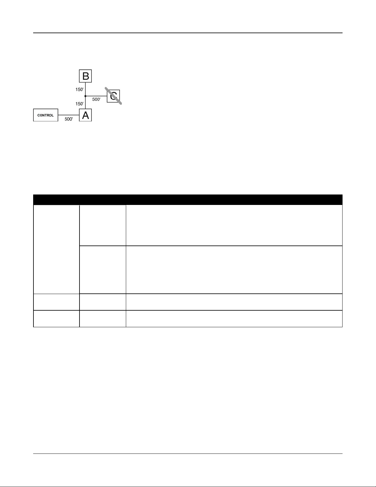
Note: Any module can be connected anywhere along the Corbus. Separate wire runs for keypads, zone expanders etc. are
not necessary.
Note: No module can be more than 1,000'/305m (in wire length) from the panel. Do not use shielded wire for Corbus wiring.
Figure 2-3 Corbus Wiring
Module (A) is wired correctly as it is within 1,000'/305m of the panel, in wire distance. Module (B) is wired correctly as it is
within 1,000'/305m of the panel, in wire distance. Module (C) is NOT wired correctly as it is farther than 1,000'/305m from the
panel.
Current Ratings
In order for the system to operate properly, the power output of the alarm controller and power supply modules cannot be
exceeded. Use the following data to ensure that the available current is not exceeded.
Table 2-1 System Output Ratings
Device Output Rating (12VDC)
AUX: 700mA. Subtract the listed rating for each keypad, expansion module and accessory
HS2016-4
HS2016
HS2032
HS2064
HS2128
BELL: 700mA. Continuous rating.
connected to AUX or Corbus. At least 100mA must be reserved for the Corbus.
2.0A. short term. Available only with standby battery connected. Not for UL/ULC or EN
certified applications.
HSM2208 AUX: 250mA. Continuous rating. Subtract for each device connected. Subtract the total load
on this terminal from the alarm panel AUX/Corbus output.
HSM2108 AUX: 100mA. Subtract for each device connected. Subtract the total load on this terminal
from the panel AUX/Corbus output.
- 16 -
Page 17
Section 2: Installation
Alarm Controller Current Calculation
Maximum (Standby or Alarm)
AUX (700mA max. including PGMs 1-4)
Corbus (700mA max.)***
PCLink+ (Alt. Com.:125mA)
Total (must not exceed 700mA)
*** See "Corbus Current Calculation Chart" on page 17.
For UL, ULC and Commercial Listed applications, the total standby and alarm current cannot exceed 700mA.
Table 2-2 Corbus Current Calculation Chart
Item Current (mA) x Quantity Total (mA)
HS2016-4/HS2016/HS2032/HS2064/HS2128 85 X 1 85
HS2LCD 105 x
HS2ICN 105 x
HS2LED 105 x
HS2LCDP 105 x
HS2ICNP 105 x
HS2LCDRF 105 x
HS2ICNRF 105 x
HS2ICNRFP 105 x
HS2TCHP 160 x
Current required for connected devices =
HSM2108* 30 x
AUXoutput current of HSM2108
HSM2208* 40 x
AUXoutput current of HSM2208
HSM2300/2204* 35 x
HSM2HOSTx 35 x
HSM2955** x
3G208(R)/TL2803G(R)/TL280(R) 125 (PCLINK) x
Total Corbus Current =
- 17 -
Page 18
Section 2: Installation
*These units draw current from the Corbus to power devices external to the module. This current must be added to the total
Corbus current. See manufacturer's specifications for the current draw of each device.
** For HSM2955 current draw refer to HSM2955 installation manual.
Line Loss
Voltage loss through wire resistance must be considered for all installations. To ensure proper operation, at least 12.5VDC
must be applied to all modules on the system (when AC is connected and the battery is fully charged). If less than 12.5VDC is
applied, system operation is adversely affected.
To correct the problem, try any or all of the following:
1. Connect a HSM2300/2204 power supply between the alarm controller and the module to provide additional power to the
Corbus.
2. Reduce the length of the Corbus run to the module.
3. Increase the gauge of wire.
Capacitance Limits
An increase in capacitance on the Corbus affects data transmission and causes the system to slow down. Capacitance
increases for every foot of wire added to the Corbus. The capacitance rating of the wire used will determine the maximum
length of the Corbus.
For example, 22-gauge, non-shielded, 4-conductor wire has a typical capacitance rating of 20 picofarads per foot (which is
20nF/1000’). For every 1000' of wire added – regardless of where it is run – the capacitance of the Corbus increases by
20nF.
The following table indicates the total wire distance allowed for the capacitance rating of the wire used:
Table 2-3 Wire Capacitance
Wire Capacitance per 1000’ (300m) Total Corbus Wire Length
15nF 5300’/1616m
20nF 4000’/1220m
25nF 3200’/976m
30nF 2666’/810m
35nF 2280’/693m
40nF 2000’/608m
2.4 Installing Modules
Remove all power from the system while connecting modules to the alarm controller.
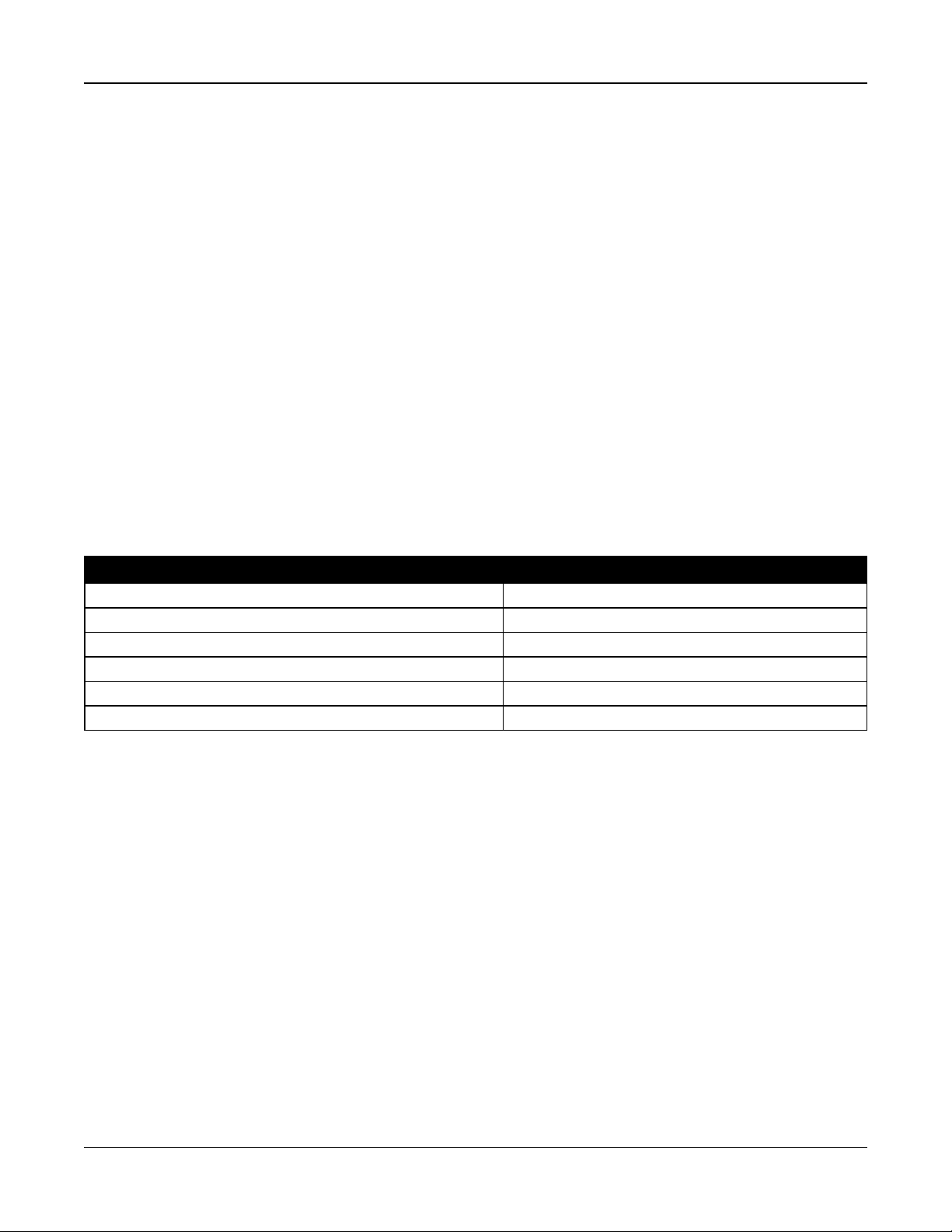
2.4.1 Zone Expander
The main alarm controller has connection terminals for zones 1 to 8. Additional HSM2108 zone expanders may be added to
increase the number of zones on the system. Each zone expander consists of one group of 8 zones. At enrollment, the zone
expander is automatically assigned to the next available zone slot. Connect the RED, BLK, YEL and GRN terminals to the
Corbus terminals on the alarm panel. Board current draw: 30mA.
- 18 -
Page 19
Section 2: Installation
Figure 2-4 HSM2108 Zone Expander
Refer to the HSM2108 installation sheet for more information.
2.4.2 Output Expander
The HSM2208 module is used to add up to 8 low-current programmable outputs to the alarm system.
The 4-wire Corbus connection is used by the panel to communicate with the module. Connect the RED, BLK, YEL and GRN
terminals to the Corbus terminals on the alarm panel. Board current draw: 40mA.
Figure 2-5 HSM2208 Output Expander
2.4.3 Wireless Transceiver Module
The HSM2HOSTx 2-way wireless integration module provides communication between wireless devices and the alarm controller.
Connect the HSM2HOSTx to the 4-wire Corbus of the alarm controller according to the following diagram.
Figure 2-6 HSM2HOSTx Wiring Diagram
After you have completed the wiring, reconnect power to the security system. Board currant draw: 35mA
- 19 -
Page 20

Section 2: Installation
2.4.4 Power Supply Wiring
The HSM2300/2204 power supply/high-current output module provides up to 1.0A of additional current and can be used to
add up to four programmable outputs (HSM2204 only) to the alarm system.
The 4-wire Corbus connection provides communication between the module and alarm panel. Connect the RED, BLK, YEL
and GRN terminals to the Corbus terminals on the alarm controller. If O1 is not used, connect to Aux with a 1K resistor. Board
current draw: 1.2A.
Figure 2-7 Power Supply Wiring
2.4.5 Keypad Wiring
To wire a keypad to the alarm controller, remove the keypad backplate (refer to the keypad installation sheet) and connect
the RED, BLK, YEL and GRN terminals to the corresponding terminals on the alarm controller.
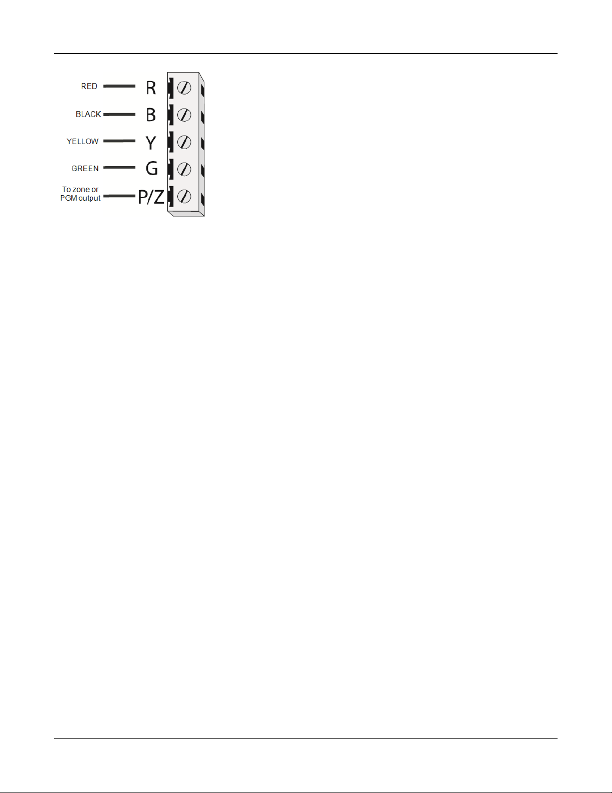
Keypad Zone/PGM Wiring
Hardwired devices can be connected to hardwired keypads with inputs (zone) or outputs (PGM). This saves from running
wires back to the control panel for every device.
To connect a zone device to HS2LCD, HS2ICON, HS2LED and HS2TCHP keypads, run one wire to the P/Z terminal and the
other to B. For powered devices, use red and black to supply power to the device. Run the red wire to the R (positive) terminal and the black wire to the B (negative) terminal.
Keypad zones support Normally Closed Loops, Single End of Line and Double End of Line.
To connect the PGM output, run one wire to the P/Z terminal and the other to R.
- 20 -
Page 21
Section 2: Installation
Figure 2-8 Keypad P/Z Terminals
Note: When using end of line supervision, connect the zone according to one of the configurations outlined in "Zone Wiring"
on page 21. End of line resistors must be placed on the device end of the loop, not at the keypad.
Assigning Keypad Zones
When using keypad zone inputs, each input used must be assigned a zone number in Installer Programming.
First, ensure that you have enrolled all installed keypads into the desired slots (See "[902] Add/Remove Modules" on page
117). Next, assign keypad zones by entering programming section [861]-[876], subsection 011 for keypads 1-16. Enter a 3digit zone number for each of the keypad zones. This number must be programmed into the slot location that the keypad is
assigned to.
Note: If a keypad zone input is assigned to zone number 1 to 8, the corresponding zone cannot be used on the main control
panel.
Once the keypad zones are assigned, you must also program zone definitions and zone attributes. See "[001] Zone Types"
on page 64 and See "Zone Setup" on page 64.
2.4.6 HSM2955 Wiring
For wiring information refer to HSM2955 Installation manual #29008435xxx.
2.4.7 Alternate Communicator Wiring
See Alternate Communicator installation manual.
2.4.8 Zone Wiring
Power down the alarm controller and complete all zone wiring.
Zones can be wired to supervise normally open devices (e.g., smoke detectors) or normally closed devices (e.g., door contacts). The alarm panel can also be programmed for single end-of-line or double end-of-line resistors.
Zone programming is done using the following programming sections:
l [001] selects zone definition
l [013] Opt [1] for normally closed or EOL; Opt [2] for SEOL or DEOL
l [201 - 208] partition assignment.
Observe the following guidelines when wiring zones:
l For UL listed installations use SEOL or DEOL only
l Minimum 22 AWG wire, maximum 18 AWG
l Do not use shielded wire
l
Do not exceed 100Ω wire resistance. Refer to the following table:
- 21 -
Page 22
Section 2: Installation
Table 2-4 Burglary Zone Wiring Chart
Wire Gauge Maximum Length to EOL Resistor (ft/meters)
22 3000 / 914
20 4900 / 1493
19 6200 / 1889
18 7800 / 2377
Figures are based on maximum wiring resistance of 100
Ω.
Normally Closed
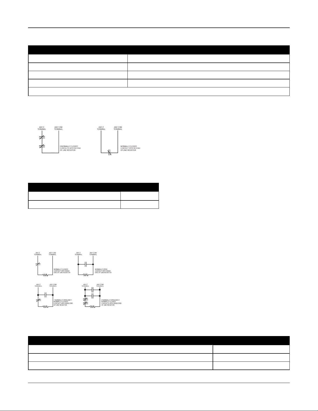
Connect hardwired devices to any Z terminal and any Com terminal. Wire normally closed devices in series.
Note: For UL Installations, do not use normally closed loops.
Figure 2-9 Normally Closed
The following table shows zone status under certain conditions for NC Loops:
Table 2-5 NC Loop Status
Loop Resistance Loop Status
0Ω(shorted wire, loop shorted) Secure
Infinite (broken wire, loop open) Violated
Single End-of-Line (SEOL) Resistor
When SEOL resistors are installed at the end of a zone loop, the alarm panel detects if the circuit is secure, open, or shorted.
The SEOL resistor must be installed at the end of the loop for proper supervision.
To enable SEOL supervision, program section [013], options [1] and [2] to OFF.
Note: This option should be selected if either normally closed or normally open detection devices or contacts are used.
Figure 2-10 SEOL Wiring
The following table shows zone status under certain conditions for SEOL:
Table 2-6 SEOL Loop Status
Loop Resistance Loop Status
0Ω (shorted wire, loop shorted) Violated
5600Ω (contact closed) Secure
Infinite (broken wire, loop open) Violated
- 22 -
Page 23
Section 2: Installation
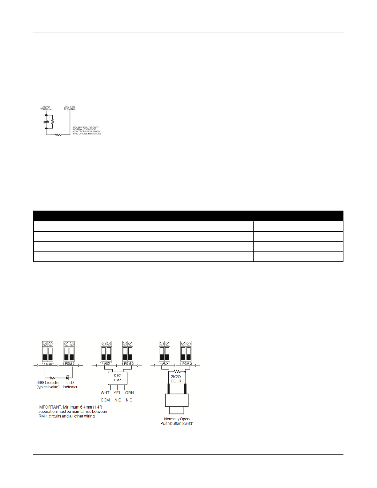
Double End of Line (DEOL) Resistors
When double end-of-line (DEOL) resistors are installed at the end of a zone loop, the second resistor enables the panel to
determine if the zone is in open, closed, tampered or faulted.
Note: Any zone programmed for Fire or 24-hr Supervisory must be wired with a SEOL resistor regardless of the type of zone
wiring supervision selected for the panel. If you change the zone supervision options from DEOL to SEOL or from NC to
DEOL, power the system down completely, then power it back up for correct operation.
To enable DEOL supervision, program section [013], option [1] to OFF and option [2] to ON.
Figure 2-11 DEOL Wiring
Note: If the DEOL supervision option is enabled, all hardwired zones must be wired for DEOL resistors, except for Fire and
24 Hour Supervisory zones. Do not use DEOL resistors for Fire zones or 24 Hour Supervisory zones.
Note: Do not wire Fire zones to keypad zone terminals if the DEOL supervision option is selected.
Note: This option can only be selected if N/C detection devices or contacts are used. Only one N/C contact can be con-
nected to each zone.
The following table shows zone status under certain conditions for DEOL:
Table 2-7 DEOL Loop Status
Loop Resistance Loop Status
0Ω(shorted wire, loop shorted) Fault
5600Ω(contact closed) Secure
Infinite (broken wire, loop open) Tamper
11200Ω(contact open) Violated
2.4.9 PGM Wiring
Min/max operating voltages for devices, sensors and modules is 9.5VDC - 14VDC.
PGMs switch to ground when activated from the alarm controller. Connect the positive side of the device to the AUX+ terminal and the negative side to a PGM terminal.
PGM 1, 3, 4 supply up to 50mA; PGM 2 supplies up to 300mA.
A relay is required for current levels greater than 50mA or 300mA. PGM2 can also be used for 2-wire smoke detectors, 24-hr
burglary input alarm.
Note: Use SEOL resistors on Fire zones only.
Figure 2-12 LED Output with Current Limiting Resistor and Optional Relay Driver Output.
- 23 -
Page 24
Section 2: Installation
UL Compatibility ID For FSA-210B Series is: FS200
Note: For ULC listed installations, use FSA-210A and FSA-410A series.
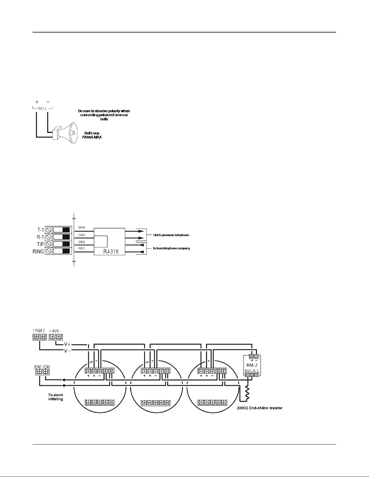
2.4.10 Bell Wiring
These terminals supply 700mA of current at 10.4 - 12.5VDC for commercial/ residential installations. To comply with NFPA
72 Temporal Three Pattern requirements, section [013] Opt [8] must be ON. Note that steady, pulsed alarms are also supported.
Figure 2-13 Bell Wiring
The Bell output is supervised and power limited by 2A thermistor. If unused, connect a 1000Ω resistor across Bell+ and Bell-
to prevent the panel from displaying a trouble. See "[*][2] Trouble Display" on page 44.
2.4.11 Telephone Line Wiring
Wire the telephone connection terminals (TIP, Ring, T-1, R-1) to an RJ-31x connector as indicated in the following diagram.
For connection of multiple devices to the telephone line, wire in the sequence indicated. Use 26 AWG wire minimum for wiring.
Figure 2-14 Telephone Line Wiring
Note: Ensure that all plugs and jacks meet the dimension, tolerance and metallic plating requirements of 47 C.F.R. Part 68,
Sub-Part F. For proper operation, no other telephone equipment must be connected between the control panel and the telephone company facilities.
2.4.12 Smoke Detector Wiring
All zones defined as Fire must be wired according to the following diagram:
Figure 2-15 Smoke Detector Wiring
- 24 -
Page 25
Section 2: Installation
See "[001] Zone Types" on page 64 for fire zone operation.
Note: Smoke detectors must be latching type. To reset a smoke detector, enter [*][7][2].
Table 2-8 Compatible 4-Wire Smoke Detectors
FSA-410B FSA-410BLST FSA-410BRST
FSA-410BT FSA-410BR FSA-410BLRST
FSA-410BS FSA-410BRT
FSA-410BST FSA-410BRS
Current ratings for DSC FSA-410 Series: 25mA - 90mA
Fire Zone Wiring: 2-wire Smoke Detectors
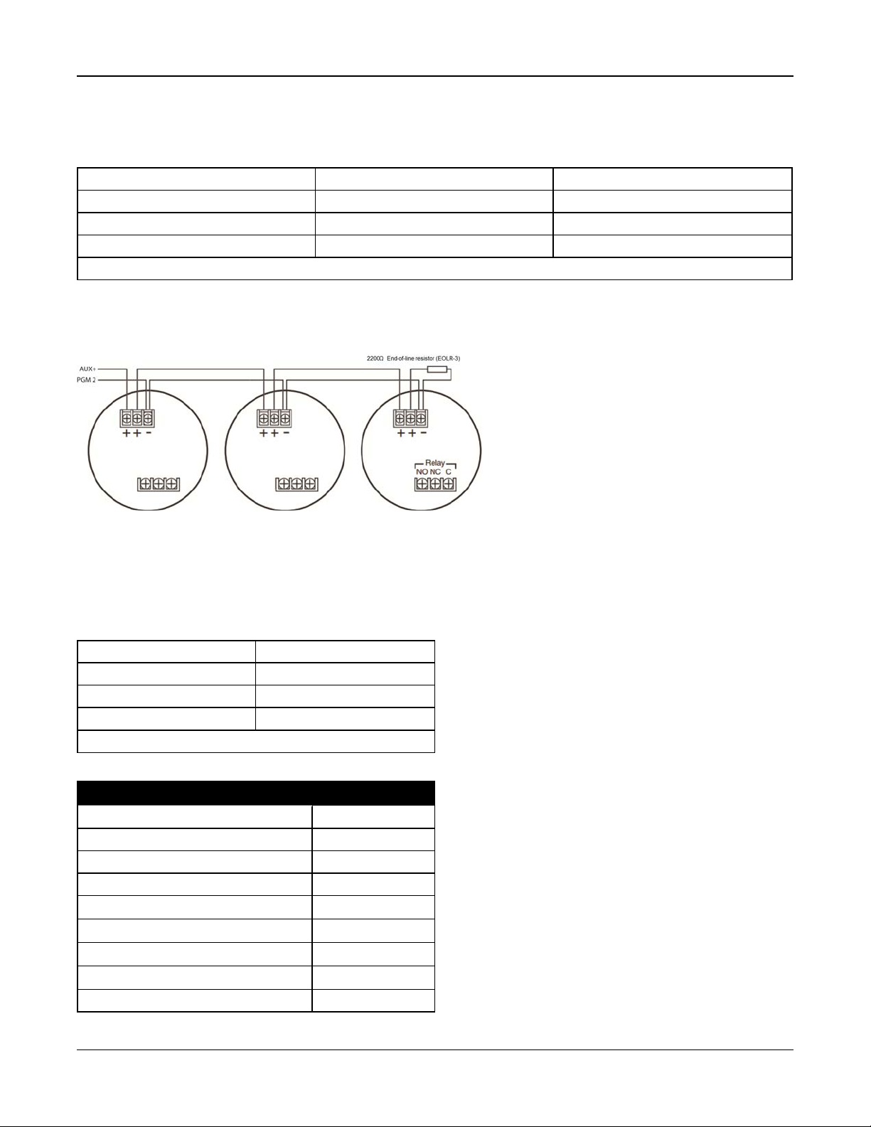
If PGM 2 is programmed for 2-wire smoke detector connection, the detectors must be wired according to the following diagram:
Figure 2-16 2-Wire Smoke Detector Wiring
Note: Additional 2-wire smoke detectors must be connected in parallel as shown above. The maximum number of smoke
detectors on a 2-wire loop is 18.
Note: Do not combine smoke detector models from different manufacturers on the same circuit. Operation may be impaired.
Refer to the smoke detector installation sheet when positioning detectors.
Table 2-9 Compatible 2-Wire Smoke Detectors
FSA-210B FSA-210BR
FSA-210BT FSA-210BRT
FSA-210BS FSA-210BRS
FSA-210BST FSA-210BRST
Current ratings for DSC FSA-210B series: 35mA - 75mA
Table 2-10 2-Wire Smoke Detector Initiating Circuit
Item Specification
Style/Class, Supervised, Power Limited Style B (Class B)
Compatibility Identifier HS2-1
DC Output Voltage 9.7-13.8 VDC
Detector Load 2mA (MAX)
Single End of Line Resistor (SEOL) 2200
Loop Resistance 24Ω(MAX)
Standby Impedance 3000Ω(NOM)
Alarm Impedance 1200Ω(MAX)
Alarm Current 86mA (MAX)
Ω
- 25 -
Page 26
Section 2: Installation
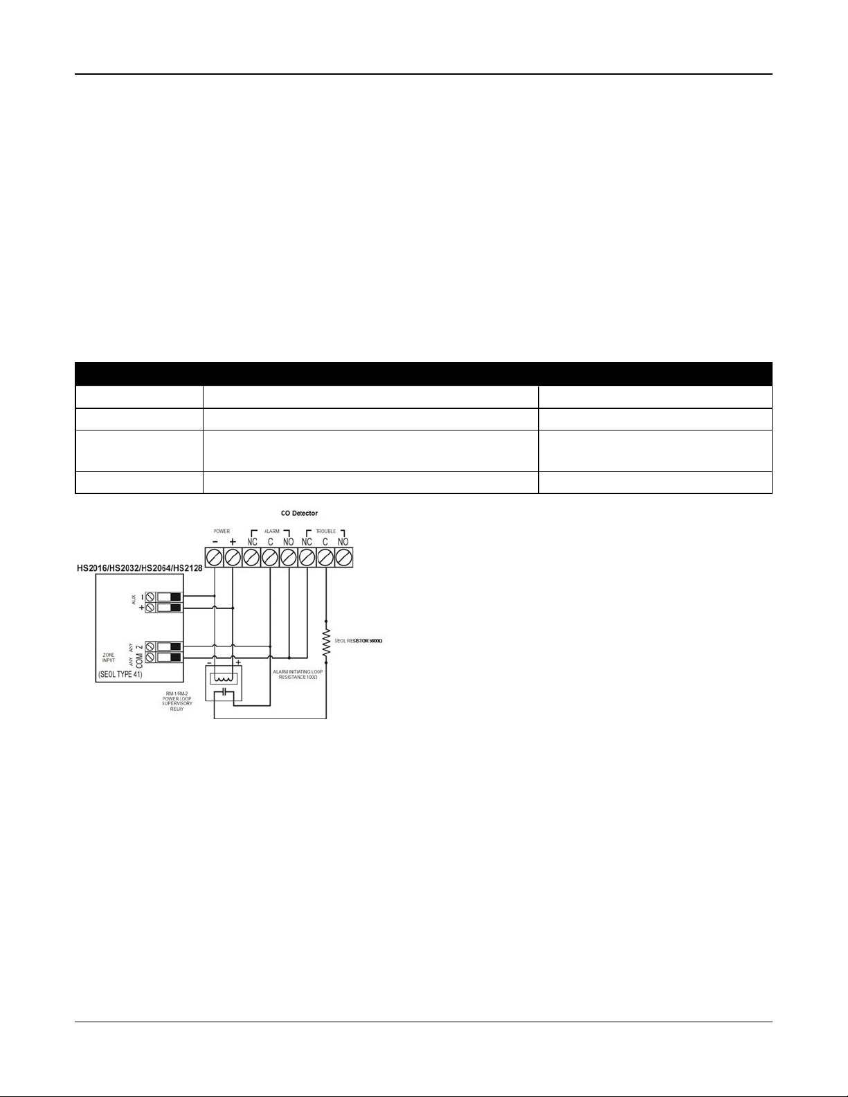
2.4.13 CO Detector
The following hardwired CO detector models can be used with PowerSeries Neo alarm controllers:
l Potter Model CO-12/24, UL File E321434
l Quantum Model 12-24SIR, UL File E186246
l NAPCO Model FW-CO12 or FW-CO1224, UL File E306780
l System Sensor Model CO1224, UL File E307195
Note: For multiple unit connections, the leads between CO detectors must be broken. The power supervision relay must be
powered from the last detector in the loop.
Wireless CO detectors are also available. When installing wireless CO detectors, use only model PG9913UL, PG8913,
PG4913. An HSM2HOSTx (x=9UL/8/4) wireless receiver or HS2LCDRF(P)x/HS2ICNRF(P)x (x=9UL/8/4) wireless keypad are
required when installing wireless CO detectors. For more details on these wireless devices, refer to their respective installation manuals.
Note: Use onlyULapproved devices with UL/ULC listed systems.
Table 2-11 CO Detector Ratings
Device Description Max Rating @12VDC
CO-12/24 Potter model CO detector 40mA
12-24SIR Quantum model CO detector 75mA
FW-CO12
FW-CO1224
CO1224 System Sensor model COdetector 40mA
NAPCO model CO detector 90mA
Figure 2-17 CO Detector Wiring
- 26 -
Page 27
Section 2: Installation
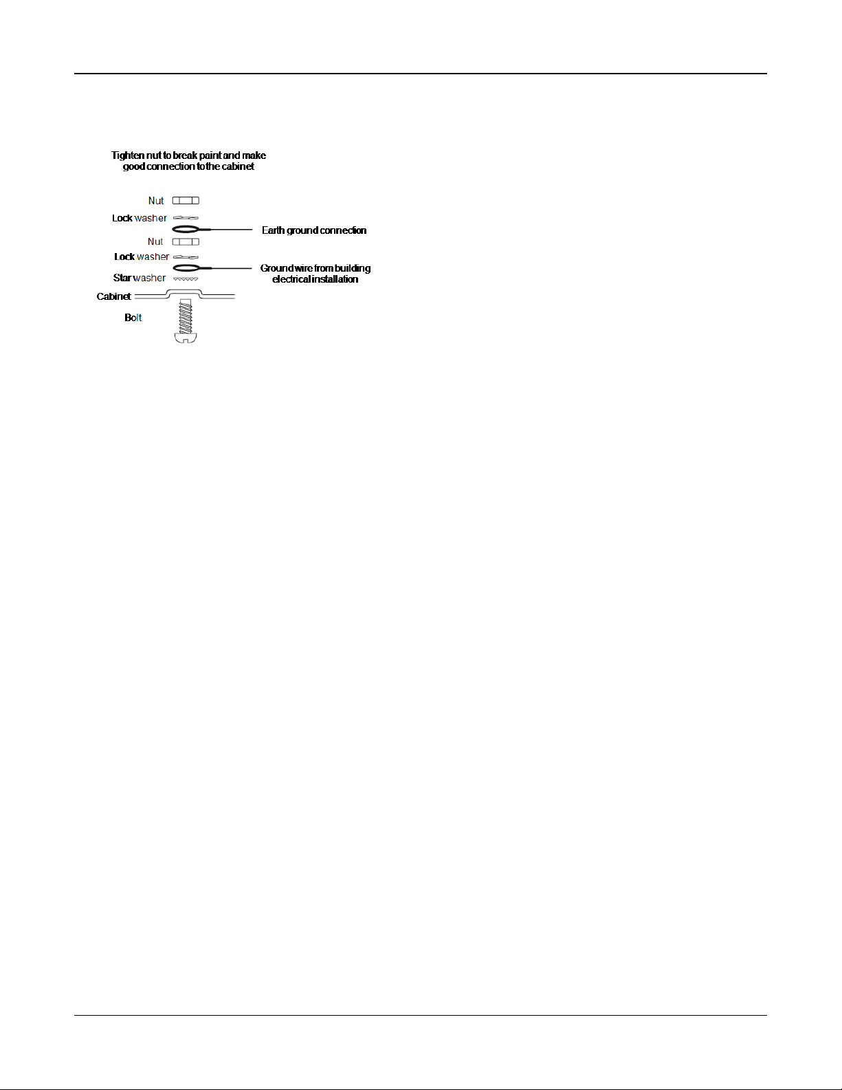
2.4.14 Ground Wiring
Figure 2-18 Ground Installation
Note: Using an insulated green wire (minimum 22AWG), connect the EGND terminal on the Corbus and the grounding wire
from the building electrical installation to any of the available holes on the back or side of the metal cabinet. See the diagram
attached to the cabinet for suggested GND point location and hardware recommendations.
Note: Wire and installation hardware not included.
2.4.15 Connecting Power
Batteries
Do not connect the battery until all other wiring is complete.
Note: A sealed, rechargeable, lead acid battery or gel type battery is required to meet UL requirements for power standby
times.
Connect the RED battery lead to the positive battery terminal and the BLACK battery lead to the negative battery terminal.
The panel can be programmed to charge the battery at 400mA or 700mA. (See "[982] Battery Settings" on page 120).
Note: Refer to "Aux Loading and Battery Selection" on page 1.
Battery Selection Chart
After calculating the battery capacity (B) for each specific installation use the following table to determine the battery
required to support the main panel in standby mode for
l 4 hours (UL commercial burglary/residential burglary),
l 12 hours (EN50131),
l 24 hours (UL/ULC residential fire, ULC commercial burglary, ULC commercial fire monitoring - no bell load allowed;
INCERT [Belgium]) or
l 36 hours (NFA2P [France]).
The battery size is measured in amp hours (Ah). The current values in the table denote the maximum current draw permitted
to achieve the desired standby time with the listed battery types.
- 27 -
Page 28

Section 2: Installation
Table 2-12 Standby Battery Guide
Battery Size Desired Standby Time
4h 12h 24h 36h
4Ah 700mA ------ ------ ------
7Ah 700mA 500mA 250mA ------
14Ah
(use 2 x 7Ah batteries
connected in parallel,
UL/ULC installations
only )
18Ah ------ ------ ------ 300mA*
26Ah ------ ------ ------ 500mA*
* use 2 x 7Ah batteries connected in parallel, UL/ULC installations only
Note: Battery capacity deteriorates with age and the number of charge/discharge cycles. Replace every 3-5 years.
Refer to See "Regulatory Approvals" on page 208 for detailed Aux. loading and battery charging information.
700mA 470mA ------
Connecting AC Power
The alarm controller requires a 16.5V, 40VA transformer. While unplugged, connect the transformer to the AC terminals on
the controller. The alarm controller can be programmed to accept a power line frequency of either 50Hz AC or 60Hz AC. See
programming section [024], option [1].
Note: For UL/ULC installations use only 60Hz.
Note: For ULC S559 applications, Standex transformer (Model FTC3716) shall be employed for direct-wiring.
- 28 -
Page 29

Section 3: Configuration
3.1 Basic Configuration Steps
Once basic installation of the alarm panel is complete, the following general configuration options should be set:
l create partitions, See "Working with Partitions " on page 32
l assign keypads to partitions, see "Keypad Partition Setup " on page 33
l assign sirens to partitions, see "Bell/Siren Operation " on page 32
l create global zones, see "Global Zones " on page 33
l set up partition account codes, see "Communications" on page 34
l set up partition timers, see "System Times" on page 70
l enroll wireless modules and devices, see "Enrolling Modules" on page 30
l assign zone types, see "[001] Zone Types" on page 64, and attributes, see "[002] Zone Attributes" on page 68
l create zone labels, see "Adding Labels" on page 61
l add users, see "Assign Access Codes" on page 47
l set up the alternate communicator if equipped, see "Alternate Communicator Setup" on page 35
l program phone numbers, see "System Communications" on page 106
l set up call directions for the central monitoring station, see "System Communications" on page 106
l set up system timers, see "System Times" on page 70
l configure reporting codes, see "Reporting" on page 100
l test the system, see "Testing the System" on page 36
3.2 Using the Keypad
The PowerSeries Neo alarm panel is compatible with several different keypad types (see "Compatible Devices" on page 9);
However, all keypads have certain basic functionality in common.
3.2.1 Special Keys
Scroll symbols < > on keypads with LCD displays indicate that options can be viewed by pressing the scroll keys.
These keys can also be used to position the cursor.
The [*] key is similar in function to the “Enter” key on a personal computer. It is generally used to accept the existing programming option. It is also the first key entry for [*] commands and can be used to enter the letters A-F when in Installer Programming mode.
The [#] key is similar in function to the “ESC” (escape) key on a personal computer. It is generally used to exit the current programming section or to return to the previous one.
3.2.2 LED Indicators
Keypads have the following status lights that provide visual indication of basic system status:
Ready: Panel is ready to be armed.
Armed: Panel is armed.
Trouble:
AC Power: ON=AC present. OFF=AC absent.
Panel Status LED Operation
The red status LED, located on the alarm controller PCB, indicates the following:
l Power up sequence – flashes rapidly until the end of the power-up sequence.
l Firmware indication – flashes during the firmware upgrade process. If the firmware upgrade fails, the LED flashes rap-
l Trouble indication – Flashes when troubles are present. Troubles are indicated according to the following priority:
System trouble. Enter [*][2] to view troubles.
idly.
1 flash - no keypads enrolled
2 flashes - module supervision trouble
3 flashes - bus low voltage
- 29 -
Page 30

Section 3: Configuration
4 flashes - low battery trouble
5 flashes - AC trouble
6 flashes - AUX trouble
7 flashes - bell trouble
8 flashes - TLM trouble
How to Enter Data
Conventions Used In This Manual
Brackets [] indicate numbers or symbols that must be entered on the keypad.
e.g., [*][8][Installer Code][804] requires the following key entries:
[*][8][5555][804]
[*] initiates a special command.
[5555] is the default installer code. The default installer code should be changed during initial programming of the system.
[804] indicates the particular programming section being accessed.
Entering Letters Manually (System Labels)
1. In Installer Programming, enter the section requiring text input.
2. Use the arrow keys [<][>] to move the cursor to a blank space or existing character.
3. Press the number key corresponding to the appropriate letter. Each number button accesses three letters and a number.
The first press of the number key displays the first letter. The second press displays the second letter, etc.
1
A, B, C, 12D, E, F, 23G, H, I, 3
4
J, K, L, 45M, N, O, 56P, Q, R, 6
7
S, T, U, 78V, W,X, 89Y, Z, 9,0
4. To select lower case letters press [*]. The Select Options list opens. Scroll to “lower case” and press [*] again to select.
5. When the required letter or number is displayed use the arrow keys [<][>] to scroll to the next letter.
6. When finished, press the [*] key, use the [<][>] keys to scroll to “Save” then press [*].
7. Continue from step 2 until all labels are programmed.
For information on entering hexadecimal data, see "Programming Hex and Decimal Data" on page 60.
0
Space
3.3 Enrollment
All optional modules and devices must be enrolled on the system. During enrollment, the electronic serial number (ESN) of
each device is identified to the control panel and zones are assigned. A wireless transceiver HSM2HOST or an RF keypad
must be enrolled first before wireless devices can be enrolled.
3.3.1 Enrolling Modules
During automatic and manual enrollment, if an attempt is made to enroll more than the maximum number of modules, an
error tone sounds and a message is displayed on LCD keypads.
Table 3-1 Module Capacity
Module HS2016-4 HS2016 HS2032 HS2064 HS2128
HSM2108 8 Zone expander 1 1 3 7 15
HSM2208 8 Output expander 2 2 4 8 16
- 30 -
Page 31

Section 3: Configuration
Module HS2016-4 HS2016 HS2032 HS2064 HS2128
Wireless Keypad:
8 8 8 8 16
HS2LCDRF(P)4
HS2ICNRF(P)4
HS2LCDWF(P)(V)4
HS2TCHP Touchscreen Keypad 8 8 8 8 16
HSM2300 Power Supply 1A 3 3 3 3 4
HSM2204 4 High-current Output 1 1 1 3 4
HSM2HOSTx Transceiver 1 1 1 1 1
HSM2955
1 1 1 1 1
(not UL evaluated)
Modules can be enrolled automatically or manually using section [902] of Installer programming. For instructions on
enrolling modules, see "Module Programming" on page 117.
To confirm that a module has been successfully enrolled, use Installer Programming section [903]. See "[903] Confirm Module" on page 118 for details.
Enrolling the First Keypad
To enroll a hardwired keypad, connect the keypad to the alarm controller, power up the alarm panel then press any button
on the keypad.
To enroll a wireless keypad, first connect the HSM2HOSTx wireless integration module to the alarm controller. Next, power
up the alarm panel and a wireless keypad. Press any button on the keypad to enroll it on the HSM2HOSTx. The
HSM2HOSTx is then enrolled on the alarm panel. To enroll other keypads, see "Module Programming" on page 117.
3.3.2 Module Supervision
By default, all modules are supervised upon installation. Supervision is enabled at all times so that the panel can indicate a
trouble if a module is removed from the system.
To check which modules are currently connected and supervised, see "[903] Confirm Module" on page 118.
If a module is connected but is not recognized by the system, it may be due to any of the following reasons:
l the module is incorrectly wired to the alarm controller
l the module has exceeded its maximum wire run length
l the module does not have enough power
l the module is not enrolled on the wireless receiver
Removing Modules
Enrolled modules can be deleted from the system via programming section [902]. For instructions, see "[902] Add/Remove
Modules" on page 117.
3.3.3 Enroll Wireless Devices
Wireless devices are enrolled via the wireless transceiver module and Installer Programming section [804][000]. See "Compatible Devices" on page 9 for a list of supported wireless devices.
Wireless devices are enrolled using one of the following methods:
Auto Enrollment
To enroll a wireless device using this method, press and hold the Enroll button on the device for 2-5 seconds until the LED
lights then release the button. The alarm panel automatically recognizes the device and the keypad displays a confirmation
message. The device ID and next available zone number are displayed. Press [*] to accept or scroll to another available
zone number. Batteries must be installed in the wireless device in order to enroll.
Various zone features are programmable depending on the type of device. See "Zone Setup" on page 64 for details.
- 31 -
Page 32

Section 3: Configuration
Pre-Enrollment
Pre-enrollment is a two step process. The first step requires entering each device ID ([804][001]-[716]). Every wireless device
has an ID printed on the sticker attached to the device. The format is XXX-YYYY where:
l XXX identifies the type or model of the device
l YYYY is a short encrypted ID used by the system to identify the specific device
Pre-enrollment can be done at a remote location and using DLS/SA. The second step is to press the enrollment button on
the device, usually done on location. Installer Programming does not have to be entered at this step. Both steps must be performed in order to complete the enrollment.
3.4 Working with Partitions
A partition is a limited area of the premises that operates independently from the other areas. Partitioning a system can be
beneficial if the property has outbuildings that need to be secured independently of a main area or if the home has a separate apartment.
Each partition can have its own keypad or a keypad can have access to all partitions (only if all partitions belong to the same
owner). User access to partitions is controlled via access codes. A master code can access the entire system and partitions,
while a user code is limited to assigned partitions.
Setting up a partition requires configuration of the following:
l create the partition
l define bell/siren operation
l assign keypads
l assign zones
l assign users
3.4.1 Setting Up a Partition
Partitions are added or removed from the system by applying or removing a partition mask via Installer Programming section
[200]. The number of available partitions depends on the alarm panel model. See "[200] Partition Mask" on page 98 for more
information.
3.4.2 Bell/Siren Operation
Each partition must have a siren. The system siren connected to the bell output of the alarm controller can be mounted in a
central location within hearing range of all partitions. Each partition can also have wireless sirens activated only on the
assigned partition. See "Wireless Programming" on page 116 for details.
Single Siren Output Operation
With a siren shared across all partitions, control over activation/deactivation of the output depends on the partition that initiated the alarm sequence. Only the partition that originated the alarm can deactivate the bell output.
Global zones, such as smoke detectors shared by multiple partitions, can deactivate the siren on all partitions the zone is
assigned to.
Multiple Siren Output Operation
When multiple sirens are used in the installation, they can be programmed to sound alarm conditions for all partitions, or for
individual partitions by using a partition enable mask.
If hardwired sirens are used, this is accomplished via bus power supplies with a supervised high-current output. The output
is then programmed as a Fire and Burglary PGM output type.
Note: Only the first output of the HSM2204 output module has bell supervision. Some conditions, such as an installer system
test, may override the partition assignment and cause all sirens to activate. User system tests only activate the sirens/outputs
assigned to that partition.
- 32 -
Page 33

Section 3: Configuration
3.5 Trouble Indicators
Both audible and visual trouble indications are available on all partitions. For more information, see "[*][2] Trouble Display"
on page 44.
Programming section [013] option 3 controls whether or not troubles are indicated when the alarm system is armed.
3.6 Keypad Partition Setup
Keypads can be configured to control an individual partition or all partitions. In general, a partition keypad controls the partition it is assigned to. A Global keypad controls all partitions. Global keypads should be placed in common areas of the
premises, such as points of entry or reception areas, where the ability to arm and disarm more than one partition at a time is
required.
Partition keypads can also be temporarily loaned to other partitions.
To select a keypad operating mode:
1. Enter Installer Programming: [*][8][installer code].
2. Select [861]-[876] to program keypads 1-16.
l Press [000] for partition assignment.
l For Global operation, key in 00.
l To assign a keypad to a partition, key in 01-08 for partition 1-8.
3. Press the [#] and reapeat step 2 for next keypad. When finished programming all keypads, press the [#] key twice to exit
programming.
Users are assigned partition access rights via the [*][5] menu.
3.6.1 Loaned Partition Setup
To loan a keypad to another partition:
1. Press and hold [#]. The keypad switches to Global display.
2. Select a partition by pressing digits 1 to 8. The keypad is temporarily loaned to another partition.
If the keypad is inactive for more than 30 seconds, it reverts to its assigned partition.
3.6.2 Global Zones
If a zone is added to more than one partition, it becomes a global zone. A global zone is only armed when all assigned partitions are armed and is disarmed when any assigned partition is disarmed.
Global zones behave as follows:
l A global Stay/Away type zone is not activated until all partitions the zone is assigned to are armed in the Away mode.
Interiors must be activated on all partitions for the global Stay/Away zone to be active.
l A shared zone bypassed on one partition is bypassed on all partitions the zone is assigned to.
l An entry delay started on a global zone sounds an entry delay on all keypads assigned to partitions the global zone
is assigned to.
l A global Delay type zone follows the longest programmed delay time of the partitions it is assigned to.
3.6.3 Fire and CO Zone Types
Fire zones only place the partition they are assigned to into alarm. Other partitions retain their current state.
A fire reset only resets partitions they are assigned to.
One or more fire zones may be located on any partition.
On alarm, the fire auto-scroll display appears on all partition keypads and on all global keypads. Fire alarm silence and fire
system reset may be done directly on any partition keypad. To silence a fire or CO alarm from a global keypad requires that
the global keypad be loaned to one of the partitions the zone is assigned to.
- 33 -
Page 34

Section 3: Configuration
3.6.4 Bell/PGM Support
PGMs must be assigned to one or more partitions. See section [007] for partition assignment.
Note: Bell PGM type requires supervision and follows arming squawks by partition.
3.6.5 Communications
Account codes are assigned to all system and partition events.
For SIA communications, a single account code (programmed in section [310][000]) is used for all events. The partition is
identified via Nri1-8. System events use Nri0.
When using communication formats other than SIA, individual account codes can be programmed for each partition. See "
[310] Account Codes" on page 106.
3.6.6 Assign Zones
Partition zone assignments are completed using sections [201] - [208] for partitions 1 - 8. Subsections [001 - 016] are then
used to enable or disable banks of 8 zones on the partition.
3.6.7 Assign Users
Acess [*][5] using the master code, select the desired user code and enter digit 4 to modify the partitions that can accept the
user code.
3.6.8 Factory Defaults
Individual modules, as well as the alarm panel itself, can have their programming returned to factory default settings. Hardware is defaulted via the following Installer Programming sections:
l [991] Default Keypads
l 000 – Default all keypad programming
l 001-016 – Default keypads 1-8
l [993] Default alternate communicator
l [996] Default wireless receiver
l [998] Default HSM2955
l [999] Default system
See "Defaults" on page 121 for more information.
Default All labels
Use programming section [000][999]. The following labels are returned to factory default settings:
l Zone Label
l Partition Labels
l Module Labels
l Partition 1-8 Command Output 1 to 4 Labels
l Schedule 1 to 4 Labels
l Event Labels
l User Labels
System and module programming is not affected.
Hardware Reset Main Control Panel
Perform the following to restore the main control panel to default settings:
1. Power down the system.
2. Remove all wires between Zone 1 and PGM 1 on the alarm controller.
3. Connect a short between Zone 1 and PGM.
4. Power up the system (AC only) for 60 seconds.
5. Power down the system and remove the short.
6. Power up the system again. Factory defaults are restored.
- 34 -
Page 35

Section 3: Configuration
Hardware default is logged to the event buffer.
Note: Hardware default is not available when installers lockout is enabled.
3.7 Alternate Communicator Setup
The alternate communicator is an optional wireless or ethernet communications device that can be used as a backup to the
PSTN connection or as a primary means of communication between the alarm panel and the central monitoring station. The
alternate communicator communicates via 3G (HSPA) or Ethernet.
The following configuration steps are required to set up the alternate communicator:
l Install the alternate communicator and wire it to the alarm panel (use PCLINK_2 header)
l Enroll the alternate cellular communicator with Connect 24
l Set the communication path: [300]
l Enable the alternate communicator: [382] option 5
l Enable event reporting: [307]/[308]
l Program communication delay timer: [377]
l Program DLS access: [401] option 07
Refer to the 3G2080(R)/ TL2803G(R)/ TL280(R) installation manual for details.
3.7.1 Real Time Clock
This feature synchronizes the alarm panel time and date with that of the alternate communicator, provided real time clock
support is available. Time and date are updated at 4:05 PM or when the system time is lost. This feature is enabled/disabled
in Installer Programming section [024] option 5.
3.7.2 Communication Paths
The path of communication between the alarm panel and the central station must be established through either the alarm
panel’s on-board Public Switched Telephone Network (PSTN) connection or through the alternate communicator (cellular or
Ethernet) if equipped.
Paths to four receivers can be programmed in Installer Programming section [300] options 001 - 004.
For more information, see "[300] Panel/Receiver Communication Paths " on page 99.
3.7.3 Communications Options
The following alarm panel options must be programmed when configuring the alternate communicator:
[300] option 02: communication path (see "[300] Panel/Receiver Communication Paths " on page 99)
[380] option 01: communications enabled/disabled (see "[380] Communicator Option 1" on page 109)
[382] option 05: enable communicator and all associated options: telephone number, reporting code and call direction ("
[382] Communicator Option 3" on page 111)
[308][351]-[356] reporting codes (see "[351] Alternate Communicator 1")
[401] option 7: DLS access (see "[401] System Test Events")
3.7.4 Communication Attempt Limit
If a telephone line monitoring (TLM) trouble is present, the number of PSTN dialing attempts is reduced from the programmed value to 0 attempts. See programming section [380] Communicator Option 1 for details.
3.7.5 Supervision Restore
If the alarm system experiences a failure to communicate (FTC) with the central monitoring station, it automatically attempts
to transmit the event when communications are restored.
- 35 -
Page 36

Section 3: Configuration
3.7.6 Remote Firmware Upgrade
Firmware upgrades can be automatically pushed to the alarm panel and modules from Connect 24 or DLS. A message is displayed on LCD keypads indicating a firmware upgrade is available. On all keypads, the blue proximity tag bar flashes one
second on - one second off.
Users authorize the firmware upgrade through [*][6][Master Code][17].
During the update, a message indicating that a firmware upgrade is in progress is displayed on the LCD keypad. If the firmware update fails, an error message is displayed on LCD keypads.
Firmware updates are performed under the following conditions:
l The system is not armed
l No AC trouble is present
l No low battery trouble is present
l No FTC trouble is present
l Every alarm in memory has been viewed
l No events are being communicated
l An alternate communicator is present
Remote firmware upgrade is possible for the following modules:
l hardwired keypads, including HS2LCDRF
l wireless transceivers
l alternate communicators
Note: For UL listed installations, do not use remote programming unless an installer is on the premises.
3.8 Local Firmware Upgrade
Alarm panel firmware can be upgraded locally via DLS. Firmware upgrade prevention rules are ignored when performing a
local firmware upgrade.
Note: [382][5] must be enabled to perform a local firmware upgrade.
To perform a local firmware upgrade:
1. Remove the front cover of the alarm panel and plug the DLS header into the PCLink 2 connector on the alarm controller.
2. Open the Flash Utility within DLS, select the latest firmware file from the Web or browse to a saved flash file on your hard
drive. Follow the steps as prompted by the Flash Utility application. A message is displayed when download is complete.
3. Once the firmware update is complete, the system powers up.
3.9 Testing the System
Installer Walk Test
Walk test enables the installer to test the operation of each detector by tripping zones, causing an actual alarm. Enter section
[901] to initiate a walk test. When a zone is tripped, all system sirens emit a tone to indicate that the zone is working correctly.
After 15 minutes without zone activity, the walk test terminates automatically. To manually exit walk test mode, enter [901]
again.
3.9.1 Viewing the Event Buffer
The event buffer contains logs of events that have occurred on the alarm system beginning with the most recent. The capacity of the event buffer is scalable and can hold 500/1000 events (depending on panel model) before rolling over. The buffer
displays events according to their time stamp, beginning with the most recent. The event buffer can be uploaded using DLS.
Each event displays the time and date, a description of the event, the zone label, access code number or any other pertinent
information. To view the event buffer, press [*][6][Master Code][*].
- 36 -
Page 37

Section 4: System Operation
4.1 Arming and Disarming
The following table describes the various arming and disarming methods available.
Table 4-1 Arming/Disarming Methods
Method Description
Away Arm for 2 seconds + [Access Code*]
Stay Arm for 2 seconds + [Access Code*]
Night Arm when armed in stay mode [*][1] + [Access Code*]
Disarm [Access Code]
No-Entry Arming [*][9] + [Access Code]
Quick Arm/Quick Exit [*][0]
* - requiring an access code can be programmed in Section [015]
For detailed arming/disarming instructions, see the PowerSeries Neo User Manual.
4.2 Partition vs. Global Keypad
Keypads can be configured to control an individual partition or all partitions (see "Keypad Partition Setup " on page 33).
Loaning a keypad to another partition does not require an access code; However, no function that requires an access code
can be performed on that partition unless the user’s code has sufficient permission.
4.2.1 Single Partition Operation
Single partition keypads provide access to alarm functionality for an assigned partition.
Single partition keypads behave as follows:
l Display the armed state of the partition
l Display open zones, if the zone belongs to the partition the keypad is on
l Display bypassed zones and allow zone bypassing or creating bypass groups of zones assigned to the keypad par-
tition
l Display system troubles (system low battery, system component faults/tampers)
l Display alarms in memory that occurred on the partition
l Allow the door chime to be enabled/disabled
l Activate system test (sounds bells/PGMs assigned to the partition)
l Allow label programming (user labels for the partition)
l Control command outputs (those assigned to the partition, or global outputs such as smoke detector reset)
l Display temperature (not evaluated by UL)
4.2.2 Global/Multiple Partition Operation
Global keypads display a list of all active partitions or assigned partitions along with their current state. The Global status
screen displays the following:
12345678 (RA!N----)
R = Ready
A = Armed
! = Alarm
N = Not Ready
X = Exit Delay
E = Entry Delay
P = Pre-Alert
- = Partition not enabled
- 37 -
Page 38

Section 4: System Operation
In the following example, partition 1 is armed, partition 2 is disarmed and ready, partition 3 is disarmed and not ready, partition 4 is in alarm, partition 5 is indicating exit delay, partition 6 is in entry delay, partition 7 is in auto-arm pre-alert and partition 8 is not enabled.
1 2 3 4 5 6 7 8
A R N ! X E P -
Global keypads behave as follows:
l Troubles are displayed and sounded on the global keypad. Troubles can be viewed from the global keypad display
by pressing the right scroll key then (*). The Troubles menu is displayed. An access code may be required to enter
the [*][2] menu depending on system programming.
l Keypad function keys can be programmed for Global Stay Arm, Global Away Arm and Global Disarm.
l Multiple partition arming may be done from a global keypad assigned to the same partitions as the user.
4.3 Labels
Various custom labels can be created to make identification of the alarm system, partitions, zones and modules simpler.
Labels are created by inputting text manually, by selecting words from the Word Library or by downloading/uploading using
DLS. See "Adding Labels" on page 61
4.3.1 System Label
This feature is used to program a custom label for the security system. This label is used in the event buffer when system
events occur. The maximum label size is 14 ASCII characters.
See "[100] System Label" on page 63 for programming details.
4.3.2 Zone Labels
Customized labels can be created for each zone on the alarm system. These labels are used on various displays and events
to identify the zone. The maximum label size is 14 x 2 ASCII characters.
See "[001]-[128] Zone Labels" on page 61 for more details.
4.3.3 Partition Labels
Each partition on the alarm system can have a unique label to identify it. This label is displayed on partition keypads and
event messages. The maximum label size is 14 x 2 ASCII characters.
See "[101]-[108] Partition 1-8 Labels" on page 63 for more details.
4.3.4 Module Labels
Labels can be created for the following optional system modules:
l keypads
l 8 zone expander modules
l 8 output expander modules
l wireless transceiver
l power supply
l 4 high-current output module
l alternate communicator module
l audio module
l siren
l repeater
The maximum label size is 14 ASCII characters.
See "[801] Keypad Labels" on page 63 for more details.
4.3.5 Event Labels
Customizable labels can be created for the following events:
- 38 -
Page 39

Section 4: System Operation
l Fire alarm
l Fail to arm
l Alarm when armed
l CO alarm
The maximum label size is 14 ASCII characters. See page 61 for more details.
4.3.6 Partition Command Output Labels
This feature is used to program custom labels for command outputs. These labels are used with output activation events in
the event buffer. The maximum label size is 14 x 2 ASCII characters. See "[201]-[208][001]-[004] Partition Command Output
Labels" on page 63 for more details.
4.4 Annunciation
4.4.1 Door Chime
The keypad can be programmed to use one of four different door chime tones for each zone on the system. Chime is active
only during the disarm state. Only one door chime option can be enabled for each zone.
l Beeps
l Bing-Bong
l Ding-Dong
l Alarm Tone
l Zone Name - Voice Annunciation (HS2LCDWF keypads only)
Chime is enabled/disabled on a partition using the [*][4] command.
4.4.2 Temperature Display
Indoor and outdoor temperature can be displayed on system keypads if configured in keypad programming section [861][876]>[023] option 7, and sections [041]-[042]. Temperature is detected using wireless temperature sensors installed on the
system. Refer to "Compatible Devices" on page 9.
Global keypads only display outdoor temperature.
4.4.3 Low Temperature Warning
Keypads can be configured to detect low ambient temperature.
If the temperature at the keypad drops to 6° C ± 2° C (43° F ± 3°F), the keypad zone goes into alarm. When the temperature
rises above 9° C ± 2° C (48° F ± 3° F), the keypad zone is restored.
When this option is enabled, the keypad’s zone input functionality is disabled.
Refer to section [861]-[876]>[023] option 8 for more information.
Note: This feature has not been evaluated by UL/ULC.
4.5 Keypad Function Keys
Keypads have 5 programmable function keys that can be configured to perform one of the following actions:
Table 4-2 Function Key Programming Options
[00] Null Function Key [17] Arm Interior
[02] Instant Stay Arm [21]-[24] Command Output 1 to 4[*][71] - [*][74]
[03] Stay Arm [29] Bypass Group Recall
[04] Away Arm [31] Local PGM Activate
[05] [*][9] No-Entry Arm [32] Bypass Mode
- 39 -
Page 40

Section 4: System Operation
[06] [*][4] Chime On/Off [33] Bypass Recall
[07] System Test [34] User Programming [*][5]
[09] Night Arm [35] User Functions [*][6]
[12] Global Stay Arm [37] Time & Date Program
[13] Global Away Arm [39] Trouble Display [*][2]
[14] Global Disarming [40] Alarm Memory [*][3]
[16] Quick Exit [61]-[68] Partition 1 to 8 Select
To program a function key:
1. Enter Installer Programming [*][8].
2. Enter section [861] for keypad 1 function key programming.
3. Enter [001] to [005] to select a function key to program.
4. Enter a 2-digit number to assign a function key operation - [00] - [68]. See table above.
5. Continue from step 3 until all function keys are programmed.
6. Press the [#] key twice to exit Installer Programming.
Programmed function keys must be pressed for 2 seconds in order to activate the function.
4.5.1 Function Key Definitions
This section provides detailed descriptions of each programmable function key option.
[00] Null Functio n Key
This option deactivates the function key. The key does not perform any function when pressed.
[02] Instant Stay Arm
This feature is similar to the Stay Arm function key, except that no exit delay is applied and the system arms immediately.
If no Stay/Away zone types are programmed, the alarm system arms in Away mode.
Note: Do not use this function with CP-01 installations.
[03] Stay Arm
Only perimeter zones are armed. Interior zones are bypassed regardless of whether or not delay zones are tripped during
the exit delay.
[04] Away Arm
All interior and perimeter zones are armed. CP-01 panels require an exit through a delay zone during the exit delay or the
system will arm the perimeter zones only.
[05] No-Entry Arm [*][9]
All Delay 1 and Delay 2 zones become instant zones. If a door or window is opened the system goes immediately into alarm.
This function is typically used when no occupants are expected to return to the site during the armed period. Activation of this
function key requires an access code. This function only works while the system is disarmed.
See "[*][9] No-Entry Arming" on page 55 for more information.
[06] Chime On/Off
This function turns the door chime on or off and is the equivalent of pressing [*][4]. The alarm system must be disarmed to
use this function. If option 7 in section [023] is enabled, this function key requires an access code.
[07] System Test
This function performs a system test when pressed and is the equivalent of entering [*][6][Access Code][04]. The alarm system must be disarmed to use this function. See See "[*][6] User Functions" on page 51 for more information.
[09] Night Arm
All perimeter and interior zones, excluding Night zones, are armed. This key only works while the system is disarmed or
armed in Stay mode.
If no Night type zones are programmed, the alarm system arms in Away mode with an audible exit delay. Exit delay is silent.
Arming in this mode activates the Away Arming PGM output.
- 40 -
Page 41

Section 4: System Operation
[12] Global Stay Arm
This function arms all partitions assigned to the user in Stay mode, provided they are ready to arm. If a partition is not ready,
the system cannot be armed. An access code is required with this option.
[13] Global Away Arm
This function arms all partitions assigned to the user in Away mode, provided they are ready to arm. If a partition is not ready,
the system cannot be armed. An access code is required with this option.
[14] Global Disarming
This function disarms all partitions assigned to the user. An access code is required with this option.
[16] Quick Exit
Pushing this key allows the user to open and close an entry/exit door without disarming the system. This function is equivalent to entering [*][0] at the keypad while the partition is armed. If quick exit is not enabled on the system, or if the system is
disarmed, pressing this key causes an error tone. An access code is not required to use this key. See "[015] System Option
3" on page 87 for more information.
[17] Arm Interior
This key removes or enables automatic bypass on all Stay/Away zones (equivalent to pressing [*][1] while armed).
If this function is performed while stay armed and, Night zones are programmed, the system arms in Night mode. If no Night
zones are programmed, the system arms in Away mode. If armed in Night or Away mode, this key switches the system back
to Stay mode. Pressing this key does not switch the arming mode from Night to Away.
This key only works while the system is armed and requires an access code entry if section [015] option 4 is disabled.
[21]-[24] Command Outp ut 1 to 4
This function controls command outputs 1-4 and is the equivalent of entering [*][7][X], where X is 1, 3 or 4.
An access code is required to use this function.
Selecting command output 2 is the equivalent of pressing [*][7][2] sensor reset. See "103 – Sensor Reset [*][7][2]" on page 73
for more information.
[29] Bypass Grou p Recall
This function bypasses all zones belonging to the bypass group.
Zones must be saved in the bypass group for this function key to operate. An access code is required to use this feature if
section [023] option 4 is enabled.
Note: Do not use with wireless keys.
[31] Lo cal PGM Activate
This function controls a PGM connected to a keypad.
[32] Bypass Mo de
This function places the keypad in Zone Bypass mode. Selecting this function is the equivalent of pressing [*][1] while disarmed. If an access code is required for bypassing, the user must enter the access code before using this function. An
access code is required if section [023] option 4 is enabled.
[33] Bypass Recall
This function bypasses the same set of zones that were bypassed the last time the partition was armed. This function is equivalent to pressing [999] while in the [*][1] menu. An access code is required to use this feature if section [023] option 4 is
enabled.
[34] User Programming
This function is the equivalent of entering [*][5]. A master or supervisor access code is required to use this function. This key
only works while the system is disarmed.
[35] User F unctions
This function puts the keypad in user programming mode and is the equivalent of entering [*][6]. An access code is required
to use this function. If section [023] option 8 is off, only the Master or Supervisor code can access the [*][6] menu.
[37] Time & Date Prog ram
This function places the keypad in date/time programming mode. A valid access code is required.
- 41 -
Page 42

Section 4: System Operation
[39] Trouble Display
This function puts the keypad in trouble display mode and is equivalent to pressing [*][2]. This function only works while the
system is disarmed. This function key requires a code if section [023] option 5 is enabled.
[40] Alarm Memory
This function puts the keypad in alarm memory display mode and is equivalent to pressing [*][3]. This function only works
while the system is disarmed. This function key requires a code if section [023] option 6 is enabled.
[61]-[68] Partitio n 1 to 8 Select
This function selects partition 1-8 when the assigned key is pressed. Pressing and holding the key for 2 seconds selects the
next partition.
4.6 Language Selection
The keypad can be programmed to display messages and labels in different languages. Perform the following from the
Installer Programming menu:
1. Enter installer programming [*][8][installer code]
2. Enter section [000]>[000].
3. Select a language using the scroll buttons or by entering a hotkey:
Table 4-3 Languages
[01] – English [15] – Greek
[02] – Spanish [16] – Turkish
[03] – Portuguese [18] – Croatian
[04] – French [19] – Hungarian
[05] – Italian [20] – Romanian
[06] – Dutch [21] – Russian
[07] – Polish [22] – Bulgarian
[08] – Czech [23] – Latvian
[09] – Finish [24] – Lithuanian
[10] – German [25] – Ukrainian
[11] – Swedish [26] – Slovakian
[12] – Norwegian [27] – Serbian
[13] – Danish [28] – Estonian
[14] – Hebrew [29] – Slovenian
4. Press [#] to exit.
4.7 [*] Commands
[*] commands provide convenient access to alarm system features. The following commands are available:
[*][1] Bypass zones
[*][2] View troubles
[*][3] View alarms in memory
[*][4] Door chime on/off
[*][5] User programming
[*][6] User functions
[*][7] Command output 1-4 on/off
[*][8] Installer programming mode
- 42 -
Page 43

Section 4: System Operation
[*][9] No entry arming
[*][0] Quick arm/Exit
While in a [*] command menu, use the [*] key to select an option and the [#] key to exit to the previous screen. On an LCD
keypad, use the scroll keys to view options.
4.7.1 [*][1] Bypass or Stay/Away/Night Zones
The [*][1] command functions differently depending on whether the system is armed or disarmed.
Note: For UL/ULC listed installations, group bypass is not allowed.
When The Alarm System is Disarmed
Users can bypass individual zones or a programmed group of zones using the [*][1] keypad command. Zones are commonly
bypassed if users want to have access to an area while the partition is armed, or to bypass a defective zone (bad contact,
damaged wiring) until service can be provided. A bypassed zone does not cause an alarm.
When the partition is disarmed, all zones that were bypassed using [*][1] are no longer bypassed, except for 24-hr zones.
If the Code Required for Bypass option is enabled, an access code is required to enter bypass mode. Only access codes
with the Bypass attribute enabled can bypass zones (see "Access Code Attributes" on page 49).
Bypassing zones with an LCD keypad:
1. Ensure the system is disarmed.
2. Press [*] to enter the function menu. The keypad displays “Press [*] for < > Zone Bypass.”
3. Press [1] or [*], then key in your access code (if required).
4. Scroll to a zone or key in the three-digit zone number. Only zones enabled for zone bypassing are displayed. Enter the 3digit zone number or scroll to the desired zone and press [*] to bypass the zone.
“B” appears on the display to indicate the zone is bypassed. If a zone is open, “O” appears on the display. When an open
zone is bypassed, the “O” is replaced by “B.”
5. To clear a bypassed zone, repeat the above procedure. The “B” disappears from the display indicating that the zone is
no longer bypassed.
6. To exit bypass mode and return to the ready state, press [#].
Bypassing zones with a LED/ICON keypad:
1. Ensure the system is disarmed.
2. Press [*][1], then enter your access code (if required).
3. Enter the three-digit number of the zone(s) to be bypassed. The zone light turns on to indicate that the zone is bypassed.
4. To clear a bypassed zone, repeat the above procedure. On LED keypads, the zone light turns off to indicate that the zone
is no longer bypassed.
5. To exit bypass mode and return to the ready state, press [#].
Note: LED Keypads display the bypass status of zones 1-16 only.
Other Bypass Features:
The following features are also available on the [*][1] zone bypass menu:
Bypass Open Zones
Displays all currently open or bypassed zones. Use the scroll keys to view zones. Open zones are indicated by an (O). To
bypass a zone, press [*]. A bypassed zone is indicated by a (B).
Note: Zones with tampers or faults must be manually bypassed.
Bypass Group
Displays a programmed group of zones (bypass group) commonly bypassed. Press [*] to bypass all zones in the group.
Program Byp ass Grou p
To program a bypass group, bypass all desired zones then select Bypass Options > Program Bypass Group. The selected
zones are saved to the bypass group. When finished, press [#] to exit.
In order to program a bypass group, a master or supervisor code with access to the appropriate partition must be used.
- 43 -
Page 44

Section 4: System Operation
Bypass Recall
Press [*] while in this menu to bypass the same group of zones that were bypassed the last time the partition was armed.
Clear Bypasses
Press [*] to clear all bypasses.
Shortcut s from th e [*][1] b ase menu:
991 = bypass group
995 = program group 1
998 = bypass open zones
999 = bypass recall
000 = clear group
When The Alarm System is Armed
When the system is armed, pressing [*][1] toggles between stay, away or night arming. If a night zone is on the system, pressing [*][1] either prompts the user for an access code if required, or sounds an acknowledgment tone and changes the arming
mode.
Note: If section [022], Option 5 [Stay/Away Toggle] is on, the system does not change from Away to Stay mode.
The zone attribute for zone bypassing must be enabled (see section [002] Zone Attributes, Option 04).
Holdup zones should not be part of bypass groups.
A zone that is manually bypassed via [*][1] will bypass the alarm, fault, and tamper conditions when DEOL is used.
If a 24-hour zone is bypassed, ensure that the zone is restored or disabled before removing the bypass.
4.7.2 [*][2] Trouble Display
This feature is used to view system troubles. If a trouble is present, the keypad Trouble indicator illuminates and an audible
indication is emitted (two short beeps every 10 seconds, except while in AC failure). Silence the audible indicator by pressing [#].
Troubles may be viewed while the system is armed or disarmed. The system may be programmed to show all troubles while
armed or only fire troubles. See section [13] option 3 on page 86 for details.
The system can be configured to require a user code to view [*][2] system troubles. See section [023] option 5.
To view trouble conditions:
l Press [*][2] to enter the Trouble menu.
l On an LCD keypad, scroll to a trouble type then press [*] to view the specific trouble. The zone name and trouble con-
dition for each trouble are displayed on the screen.
l On LED/ICON keypads, zone indicator lights illuminate to identify existing trouble types (e.g., Zone light 1 represents
Service Required trouble type). Press the number key corresponding to a zone light to view the specific trouble.
Lights 1-12 illuminate to indicate the trouble as follows:
Table 4-4 : Trouble Indications
Trouble 01 – Service Required:
[01] Bell Circuit Trouble: The bell circuit is open.
[02] RF Jam: The HSM2HOSTx has detected an RF Jam condition.
[03] Aux Supply Trouble: The alarm controller, HSM2204 or HSM2300 has an overcurrent condition on Aux.
[04] Loss of Clock: System time and date require programming.
[05] Output 1 Fault: An HSM2204 module has detected an open condition on output #1.
- 44 -
Page 45

Section 4: System Operation
Trouble 02 – Battery Trouble:
[01] Panel Low Battery Trouble: The battery voltage (under load) is below 11.5V. Restores at 12.5V.
[02] Panel No Battery: No battery connected to alarm controller.
[04] HSM2204 01 - 04 Low Battery: An HSM2204 has a battery voltage less than 11.5V.
[05] HSM2204 01 - 04 No Battery: No battery connected to HSM2204.
[07] HSM2300 01 - 04 Low Battery: An HSM2300 has a battery voltage less than 11.5V
[08] HSM2300 01 - 04 No Battery: No battery connected to HSM2300.
Trouble 03 – Bus Voltage:
[01] HSM2HOSTx Bus Low Voltage: The HSM2HOSTx module has measured less than 6.3V on its Aux input.
[02] Keypad 01 - 16 Bus Low Voltage: A hardwired keypad has a bus voltage of less than 6.9V for ICON/LCD (RF version)
and 7.7V for non-RF models.
[04] HSM2108 01 - 15 Bus Low Voltage: A zone expander has a bus voltage of less than 5.9V.
[05] HSM2300 01 - 04 Bus Low Voltage: A power supply has a bus voltage of less than 6.9V.
[06] HSM2204 01 - 04 Bus Low Voltage: A high current output module has a bus voltage of less than 6.9V.
[08] HSM2208 01 - 16 Bus Low Voltage: The low current output module has detected a voltage less than 5.9V on its aux
input.
[09] HSM2955 Bus Low Voltage: The audio module has detected a voltage less than 9.65V on its aux input.
Trouble 04 – AC Troubles:
[01] Zone 001 - 128 AC Trouble: An AC trouble has been detected on a PGX934 PIR + Camera.
[03] Siren 01 - 16 AC: A siren has an AC trouble.
[04] Repeater 01 - 08 AC: A wireless repeater has an AC trouble.
[05] HSM2300 01 - 04 AC: An HSM2300 has an AC trouble.
[06] HSM2204 01 - 04 AC: An HSM2204 has an AC trouble.
[07] Panel AC: The alarm controller has an AC failure condition.
Trouble 05 – Device Faults:
[01] Zone 001 - 128: A zone is in fault. Additional information displayed on LCD keypads for the following troubles: Fire
Trouble (2-W Smoke, PGX916, PGX926), Freeze (PGX905), Self Test (PGX984), CO (PGX913), and Probe Disconnected
(PGX905). Also generated by a short on hardwired zones when DEOL is used or by a wireless supervisory fault.
[02] Keypad 01 - 16: A wireless or hardwired keypad is in fault.
[03] Siren 01 - 16: A siren is in fault.
[04] Repeater 01 - 08: A wireless repeater is in fault (supervisory or loss of AC/DC).
Trouble 06 – Device Low Battery:
[01] Zone 001- 128: Wireless zone has a low battery.
[02] Keypad 01-16: Keypad has a low battery.
[03] Siren 01 - 16: Siren has a low battery.
[04] Repeater 01 - 08: Repeater has a low battery.
[05] User 01 - 95: Wireless Key has a low battery.
Trouble 07 – Device Tampers:
[01] Zone 001 - 128 Tamper: A wireless or hardwired zone configured for DEOL operation is in tamper.
[02] Keypad 01 - 16 Tamper: A hardwired or wireless keypad is in tamper.
[03] Siren 01 - 16 Tamper: A wireless siren is in tamper.
[04] Repeater 01 - 08 Tamper: A wireless repeater is in tamper.
[05] Audio Station 01 - 04 Tamper: An audio station connected to an HSM2955 is in tamper.
- 45 -
Page 46

Section 4: System Operation
Trouble 08 – RF Delinquency Trouble:
[01] Zone 001 - 128 RF Delinquency: No response from a wireless zone for 13 minutes. This trouble prevents arming until
acknowledged or cleared using [*][2].
[02] Keypad 01 - 16 RF Delinquency: No response from a wireless keypad for 13 minutes.
[03] Siren 01 - 16 RF Delinquency: No response from a wireless siren for 13 minutes.
[04] Repeater 01 - 16 RF Delinquency: No response from a wireless repeater for 13 minutes.
Trouble 09 – Module Supervisory Trouble:
[01] HSM2HOSTx not responding.
[02] Keypad 01 - 16 not responding.
[04] HSM2108 01 - 15 not responding.
[05] HSM2300 01 - 04 not responding.
[06] HSM2204 01 - 04 not responding.
[08] HSM2208 01 - 16 not responding.
[09] HSM2955 is not responding.
Trouble 10 – Module Tamper:
[01] HSM2HOSTx Tamper.
[02] Keypad 01 - 16 Tamper.
[04] HSM2108 01 - 15 Tamper.
[05] HSM2300 01 - 04 Tamper.
[06] HSM2204 01 - 04 Tamper.
[08] HSM2208 01 - 16 Tamper.
[09] HSM2955 Tamper
Trouble 11 – Communications:
[01] TLM: Telephone line disconnected from control panel.
[02] Receiver 01-04 FTC Trouble: Failure to communicate using programmed receiver paths.
[03] Alt. Comm SIM Lock: SIM card has incorrect or unrecognized PIN.
[04] Alt. Comm Cellular: Radio or SIM card failure, low signal strength detected, or cellular network fault.
[05] Alt. Comm Ethernet: Ethernet connection unavailable. A valid IP address is either not programmed or the module was
unable to get an IP with DHCP.
[06] Receiver 01-04 Absent: Alternate communicator unable to initialize a receiver.
[07] Receiver 01-04 Supervision: Alternate communicator unable to communicate with a receiver.
[09] Alt. Comm Fault: The alternate communicator has stopped responding.
[10] Alt Comm FTC Trouble: The alternate communicator has failed to communicate an internal event not generated by the
panel.
Trouble 12 – Not Networked Troubles:
[01] Zone 001-128 Not Networked Trouble: Generated when a zone becomes out of sync with the wireless network or has
not been synchronized with the network after enrollment.
[02] Keypad 01-16 Not Networked Trouble: Generated when a keypad becomes out of sync with the wireless network or
has not been synchronized with the network after enrollment.
[03] Siren 01-16 Not Networked Trouble: Generated when a siren becomes out of sync with the wireless network or has
not been synchronized with the network after enrollment.
[04] Repeater 01-08 Not Networked Trouble: Generated when a repeater becomes out of sync with the wireless network or
has not been synchronized with the network after enrollment.
[05] User 01 - 95 Not Networked Trouble: Generated when a wireless key becomes out of sync with the wireless network
or has not been synchronized with the network after enrollment.
- 46 -
Page 47

Section 4: System Operation
IMPORTANT!
Ensure you have the following information available before contacting Customer Support :
l Alarm controller type and version, (e.g., HSM2064 1.0):
Note: Version number can be accessed by entering [*][Installer Code][900] on any LCD keypad. This information is also located on a sticker on the printed circuit board.
l List of modules connected to control panel, (e.g., HSM2108, HSM2HOSTx etc.) .
4.7.3 [*][3] Alarm Memory Display
The Memory light flashes if an alarm, tamper or fault event occurred during the last armed period or while the panel was disarmed (24 hour zones). Press [*][3] to view zones in alarm memory. To clear the memory, arm and disarm the system. When
viewing alarms in memory, LCD keypads indicate the last zone that has gone into alarm first, followed by other alarms in
numerical order.
This feature can be programmed to require an access code. See "[023] System Option 11" on page 94, option 6 for details.
A programmable function key may be configured to display alarms in memory. See "Keypad Function Keys" on page 39 for
details.
4.7.4 [*][4] Door Chime Enable/Disable
When this feature is enabled, the keypad emits a tone whenever a zone programmed as a Chime type is opened or closed.
Pressing [*][4] toggles between enabled and disabled. The door chime attribute for each zone is programmed in section
[861]-[876], subsections [101]-[228].
A function key can also be programmed to enable/disable this feature. See "Keypad Function Keys" on page 39 for details.
This feature may require an access code. See "[023] System Option 11" on page 94, option 7 for details.
The following door chime sounds may be selected:
l 6 beeps
l "Bing-Bong"
l "Ding-Dong"
l Alarm tone
l Zone Name -Voice Annunciation (HS2LCDWF keypads only)
4.7.5 [*][5] Program Access Codes
Use this section to perform the following functions:
l press [1] to program user codes 02-95, and master code 01
l press [2] to enroll a proximity tag
l press [3] to add a custom label for each user
l press [4] to assign users to partitions
l press [5] to program user attributes
Assign Access Codes
In order to access alarm system functionality, users must be added to the system. This involves creating a unique access
code and assigning attributes to each user. Access codes are programmed via the [*][5] menu.
- 47 -
Page 48

Section 4: System Operation
EN
EN
Access Code Types
The alarm system provides the following access code types:
Code Add User Delete User Arm Disarm [*][5] [*][6] [*][8]
Installer No No No No No No Yes +
Master All* All Yes Yes Yes Yes No
Maintenance No No Yes Yes No No No
User No No Yes Yes No No** No
Supervisor All but Master All but Master Yes Yes Yes Yes No
Duress No No Yes Yes No No No
One-time use No No Yes 1/day No No No
+ If section [020] option 7 is on, a user must enter [*][6][Master Code][05] to give the installer permission to access programming.
* Can only change master code if section [015] option 6 is off.
** Yes if [023] option 8 is on.
The Installer and Master codes are system codes. They can be changed but not deleted. The other codes are user-defined
and can be added or deleted as necessary. By default, access codes have the same partition and attribute programming as
the code used to program them.
Access codes are either 4 or 6 digits in length, depending on the setting of programming section [041]. Duplicate codes are
not valid.
Installer Code
This code provides access to Installer Programming [*][8]. The installer code can access all partitions and perform any
keypad function. This code can be programed by the installer in section [006][001]. The default is 5555 (4-digit) or 555555
(6-digit).
Note: For EN50131-1 approved installations the installer code cannot change the master code or any other level 3 codes.
Attempting to access the master code from the installers code generates an error tone from the system.
Master Code - Access Code [01]
By default the master code can access all partitions and can perform any keypad function. This code can be used to program
all access codes, including the supervisor and duress codes.
If section [015] option 6 is on, the master code can only be changed by the installer via Installer Programming.
The default is 1234 (4-digit) or 123456 (6-digit).
The master code can be returned to factory default settings using Installer Programming section [989].
Maintenance Code
The maintenance code can only be used to arm and disarm the system. It cannot bypass zones. Use [*][9] to arm the system,
cancel auto-arming, or perform [*][7] command functions. No arm/disarm bell squawks are sounded when the maintenance
code is used. The Maintenance code can be programed by the installer in programming section [006][003]. The default is
AAAAAA.
User Codes - Access Codes [02] to [95]
This type of access code is used to arm and disarm assigned partitions and perform other functions as programmed. It can
access the [*][6] menu if programming option [023] option 8 is on. This code cannot access the [*][5] and [*][8] menus.
User access codes are created by the master user or supervisor users.
Supervisor Codes - Access Codes [02] to [95]
A supervisor code is a user code with the Supervisor attribute enabled. Users with this attribute can access the [*][5] and [*]
[6] user code programming section for the partition they are assigned to. However, these codes can only program codes
which have equal or lesser attributes. These attributes are changeable via the [*][5] menu. A supervisor code is created by
the master user or other supervisor users.
- 48 -
Page 49

Section 4: System Operation
Duress Codes - Access Codes [02] to [95]
Duress codes function the same as user access codes, except they transmit a duress reporting code when used to perform
any function on the system.
Duress codes cannot be used to access [*][5], [*][6] or [*][8] menus.
Duress codes are created by the master user or supervisor users.
Note: Section [019] option 6 must be on to select the Duress Codes attribute.
One Time Use Code
A one time use code is a user code with the One Time User attribute enabled. This access code enables the user to arm the
alarm system an unlimited number of times. However, a user with this code can only disarm the system once per day. The
ability to disarm is reset at midnight or when the one time user code is keyed in by the master code user.
Note: One time use code cannot be applied to wireless keys.
One time use codes are created by the master user or supervisor users.
To add an access code using an LCD keypad:
1. Press [*][5][master/supervisor code] to edit access codes 02-95.
2. Use the scroll keys to select a user then press [*] to edit.
3. On the “Press (*) for Access Code” menu, press [*]. The current access code is displayed.
4. Key in the new access code. The code is saved when the last number is keyed in.
To erase an access code, select the user number and enter [*] as the first digit. All digits of the access code must be
entered.
A “-” beside a user code indicates it is not programmed. A “P” indicates the code is programmed. A “T” indicates the code is
programmed and a proximity tag is enrolled.
On an LED/ICON keypad:
1. Press [*][5][master/supervisor code]
2. Key in a 2-digit user number.
3. Press [1] to select access code.
4. Key in a new access code.
Access Code Attributes
Each user code has 6 attributes that can be toggled on or off.
The default attributes of an access code are the same as the code used to enter [*][5], whether a new code is programmed or
an existing one is edited. The available attributes are as follows:
l Supervisor
l Duress code
l Zone bypassing
l Remote access
l Bell squawk
l One time use code
1 – Supervisor
Converts standard user into supervisor user. See "" on page 47 for details.
2 – Duress Code
Converts standard user code into duress code. See "" on page 47 for details.
3 – Zone Bypassing
Users with this attribute can bypass zones. Section [023] option 4, Access code required for [*][1], must be on to use this
attribute.
4 – Remote Access
Users with this attribute can access the alarm system remotely via SMS.
- 49 -
Page 50

Section 4: System Operation
7 – Bell Squawk
When this option is assigned, the main bell squawks when the alarm system is away armed. For example, use the arm/disarm bell squawk attribute to have wireless key access codes squawk the bell, while other codes are silent. To do this, enable
this attribute on all access codes associated with wireless keys. This option is off by default for all access codes.
Note: One squawk indicates arming completed; two squawks indicates disarming completed.
Note: This feature is independent of the system option “Bell Squawk on Away Arming.” See "[017] System Option 5" on page
89
The master code's attributes cannot be changed from default. The bell squawk is off at default.
8 – One Time Use Code
Converts standard user code into one time use code. See "" on page 47 for details. Do not apply this code to users with wireless keys assigned.
Using an LCD keypad:
1. Press [*][5][Master Code].
2. Use the scroll keys to choose a user (02-95) then press [*] to select.
3. Scroll to “Press [*] for User Options” then press [*] to select.
4. Scroll to a user attribute and press [*] to toggle it on or off.
Using an LED/ICON keypad:
1. Press [*][5][Master Code].
2. Key in the 2-digit number of the access code to edit. [5] for attribute programming.
3. Press the keypad number key corresponding to an attribute to toggle it on or off.
Add User Labels
Custom labels can be programmed for each user to more easily identify them on the alarm system. Labels can be a maximum of 16 characters.
Using an LCD keypad:
1. Press [*][5] then select a user (02-95).
2. On the “Press [*] for User Labels” screen, press [*].
3. Key in the custom user label. For instructions on how to input labels, See "Adding Labels" on page 61
Assigning Proximity Tags
This section is used to assign proximity tags to users.
Note: A proximity tag cannot be assigned to the master code.
Using an LCD keypad:
1. In the [*][5] menu, select a user or enter a user number.
2. Select “Press [*] for Prox Tag”, then pass the enrolled tag near the tag reader on the keypad. A proximity tag can only be
assigned to one user at a time. Invalid (un-enrolled) proximity tags cannot be used.
To delete a proximity tag:
1. Select a user and then select Press [*] for Prox Tag.
2. Press the [*] key when prompted to delete the proximity tag.
Using an LED/ICON keypad:
1. Press [*][5][Master/Supervisor Code].
2. Key in a 2-digit user code.
3. Key in [2].
4. Pass the enrolled tag near the tag reader on the keypad.
- 50 -
Page 51

Section 4: System Operation
To increase authentication flexibility, user access can be achieved by entering a valid user code or by swiping a proximity
tag. Alternatively, users can be required to enter a valid access code and present a proximity tag. See "[040] User Authentication" on page 97.
Note: A proximity tag can not be assigned to the Master code. If a user code with a proximity tag is deleted, the proximity tag
must be re-enrolled.
Assigning Users to Partitions
Each user code must be assigned to a partition(s) in order for the user to be recognized by the alarm system. By default,
each code has the attributes of the code used to program it.
Using an LCD keypad:
1. Press [*][5][Master Code] then select a user (02-95). An “N” indicates they are not yet assigned to a partition. A “Y” indicates they are assigned to a partition.
2. Scroll to the partition assignment screen then press [*].
3. Use the number keys to assign partitions.
4. Press [#] to exit.
Note: The master code has access to all partitions and cannot be modified.
Using an LED/ICON keypad:
1. Press [*][5][Master/Supervisor Code].
2. Key in the 2-digit access code of the user.
3. Key in [4]. A zone lights illuminates to indicate which partition the user is currently assigned to. (e.g., if zone light 1 is on,
the code is assigned to partition 1).
4. Press the keypad number key corresponding to the appropriate partition (e.g., press 1 to assign the user to partition 1).
User Authentication Options
The alarm panel can be configured to accept one of two user authentication methods:
1. User code or proximity tag - the user can access the system by entering a valid code or by presenting a proximity tag.
2. User code and proximity tag - the user must enter a valid code and present a proximity tag to access the system. The
user code and proximity tag must match. For example, if the tag is associated with user 04, user code 04 must be entered
after presenting the tag. Any other user code is treated as invalid.
See "[040] User Authentication" on page 97.
Note: An access code does not have to be programmed in order for a proximity tag or wireless key to be operational.
4.7.6 [*][6] User Functions
The [*][6] command provides access to functions described below. If section [023] option 8 is on, any user code can access
this menu. If option 7 is off, only the master code can access this menu.
Event Buffer
Menu: [*][6][Master Code] > Event Buffer
Keypad: [*][6][Master Code] > [*]
This option is used to view system events stored in the event buffer.
Events are listed in the order they occurred, starting with the most recent. The time and date are listed for all events. Some
events may have a second screen with a description. An asterisk (*) on the first screen indicates that a second screen is
available.
If programmed, the event buffer automatically uploads to DLS/SA when it reaches 75% capacity. See section [410] options 3
and 5.
System Test
Menu: [*][6][Master Code] > System Test
Keypad: [*][6][Master Code] + 04
Select this option to test the alarm system's bell output, keypad buzzer and lights, communicator and standby battery.
- 51 -
Page 52

Section 4: System Operation
Time and Date
Use this section to program the alarm system clock.
Menu: [*][6][Master Code] > Time and Date
Keypad: [*][6][Master Code] + 01
Enter time and date using the following format: (HH:MM); (MM-DD-YY). Valid time entries are 00-23 hours, 00-59 minutes.
Valid date entries are 01-12 months, 01-31 days.
Other programming options that may affect this user function:
See "System Times" on page 70.
Auto- Arm/Disarm
Menu: [*][6][Master Code] > Auto Arm/Disarm
Keypad: [*][6][Master Code] + 02
With this feature enabled, the alarm system automatically arms in away mode (stay/away zones active) or disarms at a programmed time each day (see Auto-Arm Time below). The keypad emits three beeps to indicate the system is armed and one
long beep to indicate it is disarmed.
All arming inhibit features such as latching tampers, AC inhibit, etc. also inhibit Auto Arming and send the Auto Arm Cancellation code.
Auto- Arm Time
Menu: [*][6][Master Code] > Auto Arm Time
Keypad: [*][6][Master Code] + 03
This function is used to program the time of day each alarm system partition automatically arms. To program an auto-arm
time, select a day of the week and then key in the time. On LED/ICON keypads, zone lights 1-7 represent Sunday to
Saturday. Valid time entries are 00-23 hours: 00-59 minutes.
At the programmed time, the keypad buzzers beep for a programmed duration (for ULC commercial burglary installations
minimum duration is 10 minutes) to warn that automatic arming is in progress. The siren also squawks once every 10
seconds during this warning period if programmed to do so. When the warning period is complete, the exit delay elapses
then the system arms in away mode.
Auto-arming can be canceled or postponed only by entering a valid access code during the programmed warning period.
When a code is entered, the warning is silenced and auto-arming is canceled or postponed, depending on the auto-arm
postpone timer. The Auto Arm Cancellation reporting code is transmitted (if programmed).
Note: Auto-arming will not silence an active bell.
Note: The Auto Arm Cancellation reporting code is also transmitted if arming is inhibited by one of the following:
l AC / DC Inhibit Arm
l Latching System Tampers
l Zone Expander Supervisory Fault
Other programming options that may affect this function:
See "[151]-[158] Partition Auto-Arm/Disarm" on page 97
See "[014] System Option 2" on page 86
Enable DLS/Allow System Service
Menu: [*][6][Master Code] > System Serv/DLS
Keypad: [*][6][Master Code] + 05
This function enables and disables the DLS window for either 1 or 6 hours depending on the programming of section [025]
option [7].
This function also enables the end user to provide or deny access to [*][8] Installer Programming. When enabled, the
installer can access Installer Programming either by DLS or via [*8] if a pre-programmed window has been set. After the window has expired, Installer Programming is unavailable again until the window is re-opened.
Note: DLS programming is not UL tested.
Other programming options that may affect this function:
See "[020] System Option 8" on page 91, and see "[021] System Option 9" on page 93
See "[025] System Option 13" on page 96, bit "7 – 1 Hour DLS Window"
- 52 -
Page 53

Section 4: System Operation
User Call-up
Menu: [*][6][Master Code] > User Call-up
Keypad: [*][6][Master Code] + 06
When selected, this function makes a single attempt to call the downloading computer. The downloading computer must be
waiting for the call before downloading can be performed. Only one call-up is attempted. If a DLS phone number is not programmed, the alarm panel attempts to reach the DLS computer via IP connection. If the communicator is not properly configured for IP, an error tone is sounded.
User Walk Test
Menu: [*][6][access code] > Walk Test
Keypad: [*][6][access code] + 08
Selecting this function places the alarm panel into user walk test mode. The Ready, Armed and Trouble LEDs on the keypad
flash to indicate that the test is active. If zones are tripped during a walk test, the system sounds a steady 2-second tone on
all keypads to indicate that the zone is working correctly.
The walk test can be stopped at any time by re-entering [*][6][Master Code][08] on the keypad. The test automatically terminates after 15 minutes of inactivity. An audible warning begins 5 minutes prior to automatic termination.
Note: Fire and CO alarms are not tested in user's walk test. If a fire or CO alarm is detected, walk test ends automatically and the
appropriate reporting codes are sent immediately to the monitoring station. Refer to the manufacturers instructions provided with
CO and Fire detectors for testing. This feature is not available in CP-01 systems.
Late to Open
Menu: [*][6][Master Code] > Late To Open
Keypad: [*][6][Master Code] + 09
This function enables or disables the Late to Open option. This option sends a reporting code to the central monitoring station if the partition has not been disarmed by a programmed time.
Other programming options that may affect this function:
See "[201] Open/Close Events 1", option "[211] Miscellaneous Open/Close Events" on page 102.
Late to Open T ime
Menu: [*][6][Master Code] > Late To Open Time
Keypad: [*][6][Master Code] + 10
This function is used to program the time of day the partition must be disarmed by when the Late to Open option is enabled.
A separate time can be programmed for each day of the week. Valid data entries are 00:00 - 23:59. 99:99 disables the late to
open feature for the selected day.
Select a day of the week by scrolling while in the Late to Open menu, or by using keys 1-7 to select Sunday to Saturday
respectively.
SMS Programming
Menu: [*][6][Master Code] > SMS Programming
Keypad: [*][6][Master Code] + 11
This function is used to program up to 8 phone numbers for SMS command access and communications. SMS enables
users to send commands to the alarm panel via a mobile device.
Leave an SMS phone number blank to disable it. SMS phone numbers are not related to phone numbers used to dial the
central monitoring station.
Note: If SMS command and control features are disabled then this function is not accessible. See the alternate communicator installation manual for more information.
Brightness Control
Menu: [*][6][Master Code] > Brightness Control
Keypad: [*][6][Master Code] + 12
This function is used to change the brightness level of keypad display backlighting. Use the scroll keys to increase and
decrease brightness or enter a value from 00 to 15. Selecting 00 turns off keypad backlighting.
Con trast Co ntrol
Menu: [*][6][Master Code] > Contrast
- 53 -
Page 54

Section 4: System Operation
Keypad: [*][6][Master Code] + 13
This function is used to change the contrast level of keypad displays. Use the scroll keys to increase and decrease contrast
or enter a value from 00 to 15. Selecting 00 turns off keypad contrast.
Buzzer Control
Menu: [*][6][Master Code] > Buzzer Control
Keypad: [*][6][Master Code] + 14
This function is used to change the volume level of keypad buzzers.
Use the scroll keys (LCD keypads) or the [*] key (LED/ICON keypads) to increase and decrease volume or key in a value
from 00 to 15. Selecting 00 turns off the keypad buzzer.
Note: For UL/ULC listed installations, do not turn off the keypad sounder.
Autho rize Firmware Update
Menu: [*][6][Master Code] > Authorize Update
Keypad: [*][6][Master Code] + 17
This function is used to give authorization to the system to start the firmware upgrade process after all firmware upgrade files
for the keypads, HSM2HOST, control panel and alternate communicator have been fully downloaded.
Once this option is activated, the keypads and system automatically exit [*][6] and indicate that the firmware update is in progress.
Interactive Services
Menu: [*][6][Master Code] > Interactive Serv
Keypad: [*][6][Master Code] + 18
This function is used by an alternate communicator to open the Interactive Services menu.
4.7.7 [*][7] Command Outputs 1-4
Menu: [*][7][master code if required] > Output Control
Keypad: [*][7][master code if required]
This option is used to activate or deactivate command outputs 1 to 4 for each partition and enable command outputs to follow a schedule.
Using an LCD keypad:
1. Press [*][7] to enter Output Control mode.
2. Scroll to an output and press [*] to select it, or key in a command output number. The output is toggled on or off or can
activate for a fixed period of time.
3. Press [*][7][9] and enter the system master or supervisor code. Scroll to each command output and press [*] to enable or
disable the use of a programmed schedule to control the output.
Using an LED/ICON keypad:
1. Press [*][7] to enter Output Control mode.
2. Key in a command output number. The output is toggled on or off.
3. Press [*][7][9] and enter the system master or supervisor code. Press digits 1 to 4 to enable or disable the use of a programmed schedule to control the output.
Note: If no command outputs are programmed this function is not available. Other programming options that may affect this
user function:
See "121-124 – Command Outputs 1-4" on page 74
4.7.8 [*][8] Installer Programming
Use this option to place the alarm system in Installer Programming mode. Installer Programming is used to manually program alarm panel and module options. An installer’s code is required to access this function.
Installer Programming is exited automatically after 20 minutes of inactivity.
When viewing data in sections with an LCD keypad, use the [<] and [>] keys to scroll.
- 54 -
Page 55

Section 4: System Operation
Other programming options that may affect this user function:
See "[990] Installer Lockout Enable/Disable" on page 121
4.7.9 [*][9] No-Entry Arming
This function is used to arm the alarm system while occupants are on the premises. Pressing [*][9] and then keying in an
access code arms the panel without an entry delay on delay type zones and bypasses stay/away and night type zones.
After the exit delay, delay 1 and delay 2 type zones behave the same as instant zones. Stay/away zones remain bypassed.
The entry delay can be activated or deactivated at any time while the system is armed using [*][9].
Note: If the alarm system is armed using [*][9], disarming is only possible from a keypad inside the premises unless a wireless key is used.
Note: Entry of a valid access code is required following this key only when the system is disarmed. When armed, if programming section [015] option 4 (Quick Arming/Function Key) is off, an access code entry is required.
Global delay zones always have an entry delay, even if the system is armed using [*][9].
4.7.10 [*][0] Quick Arm/Exit
This feature operates differently depending on whether or not the alarm system is armed or disarmed.
When disarmed:
Pressing [*][0] arms the alarm system without having to enter an access code. This provides a fast method of arming for regular users and allows users without an access code to arm the system.
Note: The Quick Arm feature (section [015] option 4) must be enabled in order for this function to operate as intended. Function keys also will not require an access code when this option is enabled.
When armed:
This feature provides a means to exit the premises while the alarm system is armed without having to disarm then rearm it.
Pressing [*][0] starts a 2-minute timer that enables any door programmed as a delay zone to be opened and closed once
without triggering an alarm.
If the door is not closed at the end of the 2-minute timer, the entry delay sequence begins. Any additional activity on another
zone triggers the associated alarm or delay sequence.
4.8 SMS Command and Control
The user can perform certain functions on the alarm panel by remote using SMS text messages. In addition, the system
sends SMS messages to the user to confirm commands . SMS programming options are accessed through programming
section [851].
The security system only responds to SMS messages sent from designated phone numbers (programmed in section [851]>
[311]-[342]).
For more information on SMS command and control, and for a complete listing of communicator programming options, refer
to the alternate communicator installation manual.
4.8.1 SMS Command and Control Functions
The following alarm system functions are controllable via SMS:
l Stay arm the system
l Away arm the system
l Night arm the system
l Disarm the system
l Activate/deactivate command output 1-4
l System status request
l Alarm memory request
l Zone bypass
l Zone unbypass
SMS text messages must be formatted as follows:
<function name><space><partition #><space><access code>
- 55 -
Page 56

Section 4: System Operation
e.g., Stay Arm partition 1 1234
Once the command is received and executed by the alarm system, the user receives a confirmation text message.
Note: Do not use Away Arm if Push to Set [001][072] or Final Door Set [001][016] zones are programmed.
4.9 Visual Verification
This feature enables the central station operator to view captured images of the premises in the event of an alarm event.
Combination camera/motion detectors can be installed throughout the premises to provide visual verification coverage. The
microphone on the camera PIR can be disabled.
Visual verification sessions are triggered by the following:
l Fire key
l Medical key
l Panic key
l Alarms detected by armed PIRCameras
To set up video verification on a partition:
l Enroll the camera PIR; [804]
l Set video verification options; [804]>[841]:
l [001] Visual Verification Enable/Disable
l [002] View Time Window
l [003] View Other Alarms
l Input a custom label to identify the camera PIR; [000]>[001]
l Enable this option on the alternate communicator (section [10] option 2).
Refer to the Camera PIR installation manual for more details.
Note: Visual Verification has not been evaluated by UL and shall be disabled for UL certified installations.
Note: While an image is being transferred from the PIR camera to a central station receiver, the product cannot capture addi-
tional images.
- 56 -
Page 57

Section 5: Programming
5.1 How to Program
This section describes how to view alarm system programming options using the supported keypad types.
5.2 Programming Methods
The alarm system can be programmed using the following methods:
Table 5-1 Programming Methods
Method Description Procedure
Template programming
DLS programming
Installer programming
5.2.1 Template Programming
Use pre-defined templates to quickly apply basic programming
and to set up DLS downloading.
Press [899] at the “Enter Section” screen.
See Template Programming below for
details.
Download and apply programming using DLS 5 v1.3 for Neo v1.0
panels and DLS 5 v1.4+ for Neo v1.0 and v1.1 products.
For local DLS, use a PC-Link cable and
laptop with DLS-5 software installed.
For remote DLS, use a telephone line, cellular network or the Internet.
Manually program all alarm system and device options. Press [*][8][installer code] while the sys-
tem is disarmed.
Template programming allows the installer to quickly program the minimum functions required for basic operation. The
installer is prompted to enter a 5-digit code that selects predefined programming configurations:
Digit 1 – zone 1-8 definition options
Digit 2 – system EOL options
Digit 3 – alarm controller communications options
Digit 4 – alarm controller call directions
Digit 5 – DLS connection options
(See "Template Programming Tables" on page 202 for programming information).
Perform template programming after completing the hardware installation. Ensure you have the information listed below
available. Record this information in the programming worksheets for future reference:
l Monitoring station telephone number - provided by the alarm monitoring service.
l Monitoring station account code - provided by the alarm monitoring service.
l Downloading access code.
l Entry delay - installer defined.
l Exit delay - installer defined.
l Installer code - programmable, unique 4-digit code. The default value is [5555].
To perform template programming:
1. Enter [*][8][installer code][899]. If this section has been entered accidentally, press # to exit and the system programming
will not be changed.
2. At the “Enter Data” screen, enter a 5 digit value representing the desired programming options. Reference the template
programming tables to determine what values are required for the installation.
Once the 5 digit number has been entered, the installer cannot exit until all sections are completed. Enter new data
and/or press the [#] key to accept the displayed data and proceed to the next section. Changing a single digit, then
pressing the [#] key advances to the next section but does not save the changed data.
3. After entering a 5 digit template programming value, the first telephone number is displayed. Enter the monitoring station
telephone number after the “D.” Press [#] to complete the entry.
4. After programming the first telephone number, enter a system account code.
- 57 -
Page 58

Section 5: Programming
l The system account code can be any 4 or 6-digit combination of numbers (0-9) and letters (A-F).
l To enter letters A through F, press [*] then the numbers 1 through 6 for the letter A through F respectively. Press [*]
again to revert back to decimal entry. E.g., to enter “1234FF” press [1234*66].
See "[310] Account Codes" on page 106 for additional details. When the system account code programming is completed, enter a partition 1 account code using the same method as the system account code.
5. After programming the partition 1 account code, the downloading access code is displayed. Enter the new downloading
access code or press [#] to proceed to the next step. The downloading access code must changed from its default value.
6. The next value is a 3 digit partition 1 entry delay time. Press [>][>][>] to accept the default time of 30 seconds (030) or
enter an entry delay between 001 and 255. E.g., Press 020 for a delay of 20 seconds. See "[005] System Times" on page
70 for additional details. The CP-01 models of the Neo panel will not accept a value less than 30 seconds.
7. The next value is a 3 digit partition 1 exit delay time. Press [>][>][>] to accept the default time of 120 seconds or enter an
exit delay between 001 and 255. E.g., press 030 for a delay of 30 seconds. See "[005] System Times" on page 70 for additional details. The CP-01 models of the Neo panel will not accept a value less than 45 seconds.
8. After programming the exit delay, enter a 4 or 6-digit installer code, depending on the value in "[041] Access Code Digits"
on page 97. See "[006] Installer Defined Access Codes" on page 71 for installer code details.
9. Template Programming will automatically exit after the installer's code has been programmed.
5.2.2 DLS Programming
DLS programming involves downloading custom programming using DLS software and a computer. This can be done locally or by remote.
Note: For UL listed systems an installer must be on the premises.
Local Programming With PC-Link
Follow the steps below in the sequence indicated to set up local programming using DLS:
1. Connect AC Wiring.
In a new installation, the backup battery requires 24 Hrs. charging. AC Power is required for PC-Link Programming
until the battery is charged.
2. Plug the PC-Link header into the alarm controller. A DLS session is initiated on the DLS computer.
3. When the session is complete, remove the PC-Link cable from the alarm controller.
4. Complete the installation.
Remote Programming
DLS programming can be performed remotely by connecting to the alarm system via telephone line, cellular network or Ethernet.
Refer to Refer to "[401] DLS/SA Options" on page 113. for details.
Note: AC Power must be present for the alarm system to answer incoming calls from DLS.
5.2.3 Installer Programming
Installer Programming is used to manually program alarm system options. Access this mode by keying in [*][8][Installer
Code]. Use the scroll keys to navigate through the menus or jump directly to a specific section by keying in a section number.
Programming consists of toggling on and off options in each section or by populating data fields. For descriptions of all programming options, see "Programming Descriptions" on page 61.
5.2.4 Viewing Programming
Programming sections can be viewed from any system keypad. The method for viewing and selecting programming options
using LCD, LED and ICON keypads depends on the keypad type used. See below for specific instructions on programming
with each keypad type.
Generally, programming options are accessed in the following way:
1. Enter Installer Programming mode ([*][8]).
2. Navigate to a specific programming section.
- 58 -
Page 59

Section 5: Programming
41
3. Select an option to view or change its programming.
All programming options are numbered and can be accessed by navigating through the menu (LCD) or by keying in the program section number. For toggle options, the name of the option is displayed (LCD) or LEDs 1-8 are illuminated (LED and
ICON).
Use the keypad numbers to toggle options on or off. Sections requiring data input, such as phone numbers, display the full
data in fields up to 32 characters long (LCD). To input data, use the scroll keys to select a character then press the keypad
button corresponding to the number/letter required. Scroll to the next character and repeat the procedure as needed. Press
the [#] key to save changes and exit the program section.
The programming worksheets and descriptions later in this section provide a place to record custom programming settings
and are numerically listed to assist in locating specific sections.
Keypad Types
The sections below describe how programming is viewed and interpreted using each of the supported keypad types. For
more information on each keypad type, see the instruction sheet included with the keypad.
LED and ICON
Both of these keypads use LEDs to communicate information. The programming icon illuminates to indicate the alarm system is in Installer Programming mode. The Armed light turns off and the Ready light turns on while in a programming section.
Programming sections fall under two categories: those that require options to be “toggled” on or off, and those that require
data to be keyed in.
Toggle options are indicated across the top of the display using zone numbers 1-8. For example, if options 1 and 4 are on,
the display appears as follows on the different keypads:
Figure 5-1 LED and ICON displays
To enable or disable a toggle option, press the number key on the keypad corresponding to the option.
Sections requiring data input, such as phone numbers, display information in a binary format using zone LEDs 1-4 as
described in the following chart:
Figure 5-2
When a section is entered, the keypad immediately displays the first digit of information programmed. Using the example in
Figure 5 above, if zone 1 and 4 are illuminated, the first programmed digit in the section is 9. Use the scroll key [>] to
advance to the next digit.
For sections that require multiple two or three-digit numbers, the keypad beeps three times after each entry and moves to the
next item on the list. After the last digit in the section is entered, the keypad beeps rapidly eight times and exits the programming section. The Ready light turns off and the Armed light turns on.
To exit programming at any time, press the [#] key. All changes made up to that point are saved.
LCD Keypad
LCD keypads use a full-message display that provides visual and numerical navigation through the programming sections.
The Armed light illuminates when Installer Programming mode is activated. Use the scroll keys to move through menu
options and press [*] to select. Alternatively, enter a specific section number. The Armed light flashes to indicate a sub-section has been selected. Press [*] to select a sub-section. The Ready light illuminates and the information programmed in the
section is displayed.
- 59 -
Page 60

Section 5: Programming
For programming sections with toggle options, press the corresponding number on the keypad to turn the option on or off.
The display changes accordingly.
Sections requiring data input, such as phone numbers, display the full data in fields up to 32 characters long.
To input data, use the scroll keys to select a character then press the keypad button corresponding to the number/letter
required. Scroll to the next character and repeat the procedure as needed.
For information on entering HEX data, see below.
A 2-second error tone is sounded if an invalid key is pressed.
Press the [#] key to exit the program section at any time. All changes made up to that point are saved.
5.2.5 Programming Hex and Decimal Data
Hexadecimal (HEX) digits may be required during programming. To program a HEX digit, press the [*] key while in a programming section that requires a data entry. HEX programming mode activates and the Ready light begins to flash.
The following table indicates which number should be pressed to enter the corresponding HEX digit:
Table 5-2 HEX Digit Programming
Value Enter Telephone Dialer
HEX [A]
HEX [B]
HEX [C]
HEX [D]
HEX [E]
HEX [F]
Press [*][1][*]
Press [*][2][*]
Press [*][3][*]
Press [*][4][*]
Press [*][5][*]
Press [*][6][*]
Not supported
Simulated [*] key
Simulated [#] key
Dial tone search
Two-second pause
End of number
The Ready light continues to flash after the HEX digit is entered. If another HEX digit is required press the corresponding
number. If a decimal digit is required, press the [*] key again. The Ready light illuminates and the panel returns to regular
decimal programming.
Example: To enter ‘C1’ for a closing by user 1, enter [*] [3] [*], [1]
[*] to enter hexadecimal mode (Ready light flashes)
[3] to enter C
[*] to return to decimal mode (Ready light is on)
[1] to enter digit 1
If an error is made while inputting data, press the [#] key to exit the section. Select that section again and re-enter the information correctly.
When using a Contact ID format, a decimal zero [0] does not transmit for account and reporting codes. Programming a zero
[0] tells the alarm system not to send any pulses for that digit. Decimal zero [0] is a filler digit. To make a zero [0] transmit, it
must be programmed as a Hexadecimal ‘A.’
Example: For the 4-digit account number ‘4032’, enter [4] [*] [1] [*] [3], [2].
[4] to enter the digit 4
[*] to enter Hexadecimal mode (Ready light flashes)
[1] to enter A
[*] to return to decimal mode (Ready light is solid)
[3] to enter the digit 3
[2] to enter the digit 2
- 60 -
Page 61

Section 5: Programming
5.3 Programming Descriptions
This section provides descriptions of all alarm controller options programmable by the installer.
5.3.1 Adding Labels
[000] Label Programming
Zone and other labels on the alarm system can be customized.
Program labels locally or download/upload using DLS. Local label programming is done via a system keypad, as described
below.
[000] Language Selection
(LCD keypads only)
Use this section to set the language displayed by LCD keypads. To select a language:
1. Enter Installer Programming: [*][8][Installer Code].
2. Enter programming section [000]>[000].
3. Key in the 2-digit number corresponding to the language required. See below:
01 = English 11 = Swedish 22 = Bulgarian
02 = Spanish 12 = Norwegian 23 = Latvian
03 = Portuguese 13 = Danish 24 = Lithuanian
04 = French 14 = Hebrew 25 = Ukrainian
05 = Italian 15 = Greek 26 = Slovakian
06 = Dutch 16 = Turkish 27 = Serbian
07 = Polish 18 = Croatian 28 = Estonian
08 = Czech 19 = Hungarian 29 = Slovenian
09 = Finnish 20 = Romanian
10 = German 21 = Russian
[001]-[128] Zone Labels
Customized labels can be created for each available zone. Labels can be programmed at the keypad or downloaded/uploaded using DLS. The maximum label size is 14 x 2 ASCII characters.
Manual Labels
The following procedure describes how to add zone labels using the LCD keypad:
1. Enter Installer Programming: [*][8][Installer Code].
2. Press [*], scroll to Zone Labels and press [*] again.The first zone is displayed. Alternately, press [000][001].
3. Scroll to the zone label to be programmed or key in the zone number. (e.g., 001 for zone label 1).
4. Scroll to the desired character’s location using the[<] [>] keys.
5. Enter the number of the corresponding character group until the desired character is displayed (see the following table).
Example: Press the “2” key 3 times to enter the letter “F.”
Press the “2” key 4 times to enter the number “2.”
To delete a character, use the [<] [>] keys to move the cursor under the character, then press [0].
If any key other than [<] or [>] is pressed before [0], the cursor moves one space to the right and deletes that character.
6. Press [#] to save the changes and exit.
- 61 -
Page 62

Section 5: Programming
Press To Select/Display
[*] [SELECT]
[#] [ESCAPE]
[0] [SPACE]
[1] [A], [B], [C], [1]
[2] [D], [E], [F], [2]
[3] [G], [H], [I], [3]
[4] [J], [K], [L], [4]
[5] [M], [N], [O], [5]
[6] [P], [Q], [R], [6]
[7] [S], [T], [U], [7]
[8] [V], [W], [X], [8]
[9] [Y], [Z], [9], [0]
Zone Label Options
To access zone label options such as using ASCII characters, changing letter case and clearing the display, press [*] while
in Zone Label programming. The Select Option menu is displayed. Use the [<] [>] keys to access the following options:
Option Description
WORD ENTRY Provides access to the Word Library, a collection of words commonly used when programming
labels. See below for details.
ASCII ENTRY Used to access uncommon characters or as a primary method for programming labels. 255
character entries are available. Use the [<] [>] keys to scroll through the characters or enter a 3-digit
number from 000- 255. Press [*] to select a character. See "ASCII Characters" on page 215 for
available ASCII characters.
CHANGE CASE This option toggles the letter between upper case (A, B, C) and lower case (a, b, c).
CLEAR TO END This option clears the display from the cursor to the end of the display.
CLEAR DISPLAY This option clears all characters.
SAVE Saves the new label.
Word Library
The Word Library is a database of words commonly used when programming labels. Individual words can be combined as
needed (e.g., Front + Door). Words that do not fit on the first line are automatically moved to the bottom line.
To program a custom label using the Word Library:
1. Enter Installer Programming: [*][8][Installer Code].
2. Press [*], scroll to Zone Labels and press [*] again.The first zone is displayed. Alternately, press [000][001].
3. Scroll to the zone label to be programmed or key in the zone number (e.g., 001 for zone label 1).
4. Press [*] to open the Select Option menu.
5. Press [*] again to select the Word Entry option.
6. Enter the 3-digit number corresponding to a word (see "Word Library" on page 201) or use the scroll keys [<][>] to view
words in the library.
7. Press [*] to select the word.
8. To add another word, repeat the above procedure from step 4.
9. To add a space, press the right scroll key [>].
10. To clear characters, select Clear to End or Clear Display from the Select Options menu.
11. To save the current label, press [#] to exit label programming.
- 62 -
Page 63

Section 5: Programming
[051] Zone Tamper Label
This label is displayed when a zone is tampered. The maximum label size is 14 x 1 ASCII characters.
[052] Zone Fault Label
This label is displayed when a zone is in fault. The maximum label size is 14 x 1 ASCII characters.
[064] CO Alarm Message
Use this section to program a custom label that is displayed on keypads during a carbon monoxide alarm. The maximum
label size is 14 x 2 characters.
[065] Fire Alarm Message
Use this section to program a custom label that is displayed on keypads during a fire alarm. The maximum label size is 14 x
2 characters.
[066] Fail To Arm Event Message
This message is displayed on all partition keypads if a user attempts to arm the system when it is not ready to arm. The message clears after five seconds. The maximum label size is 16 x 2 characters.
[067] Alarm When Armed Event Message
This message is displayed if an alarm occurred while the system was armed. The message is displayed when the system is
disarmed and remains on the screen for 5 seconds. Following this, the zones that went into alarm are displayed. The maximum label size is 16 x 2 characters.
[100] System Label
Use this section to program a custom label for the security system. This label is used in the event buffer when system events
occur. The maximum label size is 14 x 1 characters.
[101]-[108] Partition 1-8 Labels
Use this section to program a name for each partition for display on partition keypads and event messages. The maximum
label size is 14 x 2 characters. See "Programming" on page 57 for specific instructions on how to program labels.
[201]-[208][001]-[004] Partition Command Output Labels
Use this section to program custom labels for command outputs. These labels are used with output activation events in the
event buffer. Enter subsection [201] to [208] to select partition 1 to 8, then enter subsection [001] to [004] to select command
output 1 to 4 label.
The maximum label size is 14 x 2 characters. See "Programming" on page 57 for specific instructions on how to program
labels.
[601]-[604] Schedule Labels
Use this section to program custom labels for command output schedules. These labels are used to identify schedules for
PGM command outputs 1-4. The maximum label size is 16 characters. See "Programming" on page 57 for specific instructions on how to program labels.
[801] Keypad Labels
Use this section to create custom labels for keypads on the system. Select 001-016 for keypads 1-16.
[802][001]-[015] HSM2108 Zone Expander Labels
Use this section to create custom labels for Zone expanders on the system. Select 001-015 for zone expanders 1-15.
[803][001]-[016] HSM2208 Output Expander Label
Use this section to create a custom label for the output expander. Select 001 for HSM2208. Select 001-016 for output
expanders 1-16.
[806] HSM2HOSTx Label
Use this section to create a custom label for the 2-way wireless transceiver.
- 63 -
Page 64

Section 5: Programming
[808] HSM2955 Label
Use this section to create a custom label for the 2-way wireless transceiver.
[809][001]-[004] HS2300 Power Supply Label
Use this section to create custom labels for power supplies on the system. Select 001-004 for power supply 1-4.
[810][001]-[004] HS2204 High-Current Output Supply Label
Use this section to create custom labels for high-current output supplies on the system. Select 001-004 for output supply 1-4.
[815] Alternate Communicator Label
Use this section to create a custom label for the alternate communicator.
[820][001]-[016] Siren Labels
Use this section to create custom labels for sirens on the system. Select 001-016 for sirens 1-16.
[821][001]-[008] Repeater Labels
Use this section to create custom labels for wireless repeaters on the system. Select 001-008 for repeater 1-8.
[999][Installer Code][999] Default Labels
This section is used to return all labels to factory settings. Installer code is required to verify deletion.
5.3.2 Zone Setup
The following section describes zone programming options. To program a zone type, first enter section [001] and then enter
a 3 digit zone number from 001 - 128. After entering a new zone type for the desired zone number, the keypad will automatically advance to the next zone.
[001] Zone Types
A zone type defines how a zone operates within the system and how it responds when triggered.
[001]-[128] Select Zone
Every zone on the system must be assigned a zone type. The available zone types are listed below.
000 – Null Zone
Assign to all unused zones.
001 – Delay 1
Commonly assigned to primary points of entry. Follows entry delay 1 and exit delay timers (section [005]). Arming the alarm
system starts the exit delay timer. After the exit delay has expired, opening the door starts the entry delay timer. During entry
delay, the keypad buzzer prompts the user to disarm the system.
002 – Delay 2
Commonly assigned to secondary points of entry (further from the keypad). Follows entry delay 2 timer (section [005]).
003 – Instant
Commonly used for perimeter doors and windows, this zone type follows the exit delay. The alarm is triggered instantly if the
zone is tripped after the exit delay expires.
004 – Interior
Commonly assigned to interior motion sensors near a point of entry, such as a foyer or hallway, that must be accessed to
reach the keypad. The alarm is activated if the system is armed and a delay type zone (e.g., front door) is not tripped first, or if
the entry/exit timer expires before the alarm is disarmed. Otherwise, the zone is instant if tripped.
005 – Interior Stay/Away
Similar to Interior zone type except that the system bypasses the zone when armed in Stay mode. Commonly used to activate perimeter zones while permitting free movement throughout the interior.
006 – Delay Stay/Away
Similar to delay 1 except that the zone is bypassed when armed in Stay mode. Commonly used with motion detectors that
cover an entry point.
- 64 -
Page 65

Section 5: Programming
007 – Delayed 24-Hour Fire
This zone is used with smoke detectors and functions similar to the standard fire zone, except the communicator delays the
alarm memory and transmission by 30 seconds. If the alarm is acknowledged by pressing any key, the siren is silenced and
the transmission aborted. If the smoke detector is not restored after the alarm has been acknowledged, the siren output activates after 90 seconds and another 30-second delay starts. A code is required to silence the alarm. A tamper or fault causes a
fire trouble to log and transmit.
Note: The supervision options (NC, EOL, DEOL) do not affect the functionality of this zone. The restored state of this zone
type is 5k6, the alarm state is short and the trouble state is open.
008 – Standard 24-Hour Fire
This zone is used with smoke detectors. The siren sounds instantly when the smoke detector is activated. If enabled, the communicator immediately transmits the alarm to the monitoring station. A tamper or fault of this zone type causes a fire trouble
to log and transmit.
Note: The supervision options (NC, EOL, DEOL) do not affect the functionality of this zone. The restored state of this zone
type is 5.6k, the alarm state is short and the trouble state is open.
009 – Instant Stay/Away
Commonly assigned to interior motion sensors. This zone type is bypassed when armed in Stay mode, but functions like an
Instant zone [003] when armed in Away mode.
010 – Interior Delay
Commonly assigned to interior motion sensors. When Away armed, this zone type functions like the Interior zone type. When
Stay or night armed, tripping the zone activates entry delay 1. Tripping this zone during exit delay does not cause the system
to arm in Away mode, as tripping a regular Delay type zone does.
011 – Day Zone
Commonly used in areas where immediate notification of entry is desired. When disarmed, tripping this zone activates the
keypad buzzer but does not log or report the event. When armed, tripping this zone activates the siren then logs and reports
the event.
Note: An alarm during exit delay causes the siren to activate and remain on when exit delay expires.
012 – Night Zone
Commonly assigned to interior motion detectors in areas accessed during the night. This zone functions like an Interior
Stay/Away zone [005] when armed using any method except the following: If Stay armed, this zone is bypassed; if armed
using [*][1], this zone is bypassed.
016 – Final Door Set (Non CP-01 panels only)
This zone type does not use an exit timer (infinite exit delay). The door must be opened then closed to complete the arming
sequence. The arming method determines if infinite exit delay is applied. See the table below.
Note: Disable Exit Delay Termination with this zone type.
If this zone type is bypassed, the alarm system cannot be Away armed.
Arming Method Infinite Exit Delay Arming Mode
User Code Y Away
Keyswitch Y Away
Away Key Y Away
Wireless Key Away Y Away
*0 Arm Y Away
*9 Arm N Stay
Stay Key N Stay
Wireless Key Stay N Stay
Remote Access/SMS - Do Not Use
DLS Arm N Away
NAA Arming N Away
Note: When Troubles/Open Zones Cancel Arming is enabled with this zone, any troubles or open zones on the system cancel arming when the zone is tripped and restored.
Due to the potential energy requirements of infinite exit delay, wireless keypads MUST be powered by a transformer.
- 65 -
Page 66

Section 5: Programming
If a wireless key is used to away arm the system, the door must still be opened then closed to complete the arming
sequence. The indoor siren will activate until the exit delay has expired.
017 – 24-Hour Burglary
This zone type is active at all times. It reports an alarm if the alarm system is armed or disarmed. This zone type sounds the
siren for the length of Bell time-out if the audible attribute is enabled.
018 – 24-Hour Bell/Buzzer
When the alarm system is armed and this type of zone is tripped, the siren activates for the duration of the bell time-out. If the
alarm system is disarmed when this type of zone is tripped, the keypad buzzer activates until an access code is entered.
023 – 24-Hour Supervisory
This zone is active and reports alarms at all times when tripped. The siren and keypad buzzer do not activate.
Note: The supervision options (NC, EOL, DEOL) do not affect the functionality of this zone. The restored state of this zone
type is 5.6k, the alarm state is short and the trouble state is open. For use with normally open contacts.
024 – 24-Hour Supervisory Buzzer
When tripped, the keypad buzzer emits a steady tone until a valid access code is entered.
025 – Auto Verify Fire
(Hardwired smoke detectors)
When the zone is activated, a 30-second delay begins but no fire alarm sounds. If the same zone is activated again up to 60
seconds after the delay expires, the alarm is triggered immediately. If the same zone is activated after 60 seconds, the entire
sequence begins again.
If a second fire zone is violated during the auto-verify sequence, both zones a fire alarm is immediately triggered.
(Wireless smoke detectors)
When the zone is activated, a 40-second delay begins. The alarm is triggered if the zone is still faulted after 30 seconds. If
the zone is no longer in alarm, an 80-second verification timer begins. If any fire zone is activated during this period, the
alarm is triggered.
If another fire zone is activated during the auto verify sequence, both zones go into alarm immediately.
Note: Wireless smoke detectors used with this zone type must have a built in siren to act as a pre-alert to the system alarm.
Note: The supervision options (NC, EOL, DEOL) do not affect the functionality of this zone. The restored state of this zone
type is 5.6kΩ, the alarm state is short and the trouble state is open.
027 – Fire Supervisory
When this zone is tripped, the keypad buzzer activates and a supervisory alarm is sent to the monitoring station. A valid
access code must be entered to silence the buzzer.
Note: The supervision options (NC, EOL, DEOL) do not affect the functionality of this zone. The restored state of this zone
type is 5.6k, the alarm state is short and the trouble state is open.
040 – 24-Hour Gas
Instant alarm when activated, audible alarm at default.This zone type may be assigned to any device type.
041 – 24-Hour CO
This zone type is used with CO detectors. In the event of an alarm, a distinctive siren cadence is sounded. This is followed by
a 5-second pause and then repeated. After 4 minutes, the 5-second pause is extended to 60 seconds; however, BTO must
be programmed with a value of 5 minutes or higher. The siren is silenced when an access code is entered or the siren times
out.
Note: The supervision options (NC, EOL, DEOL) do not affect the functionality of this zone. The restored state of this zone
type is 5k6, the alarm state is short and the trouble state is open. For use with normally open contacts.
042 – 24-Hour Holdup
Instant alarm when activated, silent alarm at default.
Note: Not for use in UL listed installations.
043 – 24-Hour Panic
Instant alarm when activated, audible alarm at default.
- 66 -
Page 67

Section 5: Programming
045 – 24-Hour Heat
Instant alarm when activated, audible alarm at default.
Note: For use with normally closed contacts.
046 – 24-Hour Medical
Instant alarm when activated, audible alarm at default.
047 – 24-Hour Emergency
Instant alarm when activated, audible alarm at default.
048 – 24-Hour Sprinkler
Instant alarm when activated, audible alarm at default.
049 – 24-Hour Flood
Instant alarm when activated, audible alarm at default.
051 – 24-Hour Latching Tamper
Instant alarm when activated, audible alarm at default. The alarm system cannot be armed until Installer Programming is
entered after the zone is restored.
052 – 24-Hour Non-Alarm
This zone is active at all times but does not cause an alarm. Zone attributes such as Zone Bypassing and Door Chime affect
the functionality of this zone. This zone type can also be assigned to a temperature sensor if indoor/outdoor temperature display is required without temperature warnings or alarm conditions.
056 –24 Hour High Temperature
This zone type is used with temperature sensors and is activated when the temperature rises above a programmed
threshold (set in section [804][xxx][019-020]). Instant alarm when activated, audible alarm at default. This zone type generates an alarm when the system is armed or disarmed.
Note: The temperature threshold includes a 3 °C (5-6 °F) difference between a given state and its restored condition. For
example, an alarm at 6 °C is restored at 3°C (High temperature) or 9°C (Low temperature), depending upon the zone type
selected.
The zone type for temperature sensors must be 24 Hour High/Low Temperature in order for the sensor to operate properly.
057 –24 Hour Low Temperature
This zone type is used with temperature sensors and is activated when the temperature drops below a programmed
threshold (set in section [804][xxx][019-020]). Instant alarm when activated, audible alarm at default. This zone type generates an alarm when the system is armed or disarmed.
060 – 24-Hour Non-Latching Tamper
This zone is always active and reports a tamper condition with no audible alarm when opened or tamper/faulted.
066 – Momentary Keyswitch Arm
Often used with a keyswitch module*, turning the key alternately arms and disarms the system and silences the alarms.
Tampers and faults only initiate their respective trouble sequence. The keypad gives no indication when this zone type is
activated.
Note: With audible alarm active, using the keyswitch when disarmed is the same as entering an access code at the keypad.
Using the keyswitch during the first 30 seconds of a delayed fire alarm is the same as pressing a key at the keypad (the 90
second delay starts). Activation of a keyswitch zone arms or disarms the system. Activation of this zone type is NOT logged
nor is the Police code transmitted. Bypassed zones of this type are not un-bypassed when the system is disarmed. When the
zone is bypassed, a zone bypass event buffer log and communication occurs immediately, NOT when the system is armed.
*Keyswitch module not for use in UL/ULC listed installations.
067 – Maintained Keyswitch Arm
Often used with a keyswitch module, turning the key (open state) arms the system. Turning the key back (restored state) disarms the system. Tampers and faults only initiate their respective trouble sequence.
Note: DO NOT use for wireless zones. Activation of the zone does not log or transmit the Police code. Bypassed zones of
this type are not un-bypassed when the system is disarmed. When the zone is bypassed, a zone bypass event buffer log and
communication occurs immediately, NOT when the system is armed.
- 67 -
Page 68

Section 5: Programming
With an audible alarm active, using the keyswitch when disarmed is the same as entering an access code at the keypad.
Activating this zone type during the first 30 seconds of a delayed fire alarm is the same as pressing a key at the keypad (the
90 second delay starts). If left in the open state, the system does not arm until the zone is restored and tripped again.
068 – Momentary Keyswitch Disarm
Use with a keyswitch module. Activating and restoring this zone disarms the partition and silences alarms. Tampers or faults
do not disarm the zone.
Note: Do not use as a global zone.
069 – Maintained Keyswitch Disarm
Used with a maintained keyswitch. Activating this zone disarms the partition.
Tampers or faults on this zone do not disarm the partition.
071 – Doorbell Zone
This zone type sounds a chime through keypads on the partition when activated. No alarms are generated. Various chime
tones can be programmed. Disabling door chime on the partition also disables the chime on this zone.
Note: Do not use as a global zone.
072 – Push to Set (Non CP-01 panels only)
Activating this zone starts an infinite exit delay when armed according to the methods described in the table below. To complete the arming sequence, this zone must be activated and restored. Once done, the exit delay timer starts.
Arming Method Infinite Exit Delay Arming Mode
User Code Y Away
Keyswitch Y Away
Away Key Y Away
*0 Arm Y Away
*9 Arm N Stay
Stay Key N Stay
Night Key N Night
Remote Access/SMS - Do Not Use
DLS Arm N Away
NAA Arming N Away
Do not use exit delay termination with this zone type. Away arming with this zone bypassed prevents arming.
[002] Zone Attributes
Zone attributes are used to customize the operation of zones. When a zone type (section [001]) is programmed, the default
zone attribute is automatically assigned.
When programming attributes using LED/ICON keypads:
l Ready light ON: Program attributes [1-8]
l Ready light and Armed light ON: Program attribute [9-16] (press [1] for option 9, press [6] for option 14 etc.)
l Press [9] to switch between attributes [1-8] and attributes [9-16].
Note: These attributes override default settings. Do NOT change fire zone attributes from their default settings.
[001]-[128] Select Zone
The attributes listed below can be enabled and disabled for each zone.
01 – Bell Audible
ON: An alarm activates the siren.
OFF: Silent alarm.
02 – Bell Steady
ON: Siren output is steady when in alarm.
OFF: Siren output pulses when in alarm.
03 – Door Chime
ON: The keypad chimes when the zone is open and when the zone is secured.
OFF: The zone does not chime.
- 68 -
Page 69

Section 5: Programming
EN
04 – Bypass Enabled
ON: The zone can be manually bypassed.
OFF: The zone cannot be bypassed.
05 – Force Arm
ON: The system can be armed with the zone open. The zone is temporarily bypassed and, when secured, is monitored by
the system.
ON: When open zones cancel arming is enabled [021][7], the system can begin arming with an open, force armable zone,
but if the zone is still open when the exit delay timer expires, the arming will be cancelled.
OFF: The system cannot be armed if the zone is open.
06 – Swinger Shut Down
ON: When the zone goes into alarm for the number of times programmed in the Swinger Shutdown Counter ( [377]
Communication Variables ), it shuts down with no further transmissions sent to the monitoring station. The siren follows
swinger shutdown if programmed.
OFF: Swinger shutdown is disabled. All alarms are transmitted.
07 – Transmission Delay
ON: Reporting of zone alarms is delayed for the programmed time in section 377 (See "[377] Communication Variables" on
page 107). If a valid access code is entered within this time, no alarm signal is communicated.
OFF: When an alarm occurs, the reporting code is transmitted immediately.
08 – Burglary Verification
ON: Enabled for cross zoning/police code. Zone alarms are not communicated until a burglary verified event occurs.
OFF: Not enabled for cross zoning/police code.
09 – Normally Closed (NC)
ON: The zone requires a normally closed loop.
OFF: The zone follows programming in section [013] option 2.
See note after option 11.
10 – Single End of Line (SEOL) Resistors
ON: The zone requires a single end-of-line resistor (5.6K).
OFF: The zone follows programming in section [013] option 2.
See note after option 11.
11 – Double End of Line (DEOL)
ON: The zone requires two end-of-line resistors (5.6K).
OFF: The zone follows programming in section [013] option 2.
Note: If more than 1 option is enabled for options 09, 10, and 11 the lowest attribute number takes precedence. If options 09
and 10 are both enabled the zone follows the normally closed loop configuration.
12 – Fast Loop/Normal Loop Response
ON: Follows a fast loop response of 50ms.
OFF: Follows a normal loop response as programmed in the Zone Loop Response Time section.
13 – 2-Way Audio Attribute
ON: Panel is able to initiate a 2 way audio session.
OFF: Only the microphone turns on, initiating a a Listen-in only session. The speaker remains off.
14 – Hold Up Verification
ON: An alarm from zones of this type can contribute to a verified hold up alarm. Use this attribute with Panic and Hold Up
zones.
OFF: An alarm from zones of this type does not contribute to a verified hold up alarm. The zone does not cause the hold up
verification timer to start counting down, or generate a verified hold up if the alarm is detected while the timer is running.
- 69 -
Page 70

Section 5: Programming
EN
5.3.3 System Times
This section describes how to program various timers applicable to the entire alarm system.
[005] System Times
This is the base menu used by installers to program timers, including system area [000], partition timers [001]-[008], and daylight saving time [901]/[902].
[000] – System Area
Bell Cutoff Time
System sirens follow this timer. Fire alarms follow this timer if section [014] option 8 (Fire Bell Continues Option) is off.
System tampers follow this timer. The bell cutoff time is programmed in minutes. Valid entries are 001 to 255 minutes.
Keypad buzzer alarms do not follow this timer.
Bell Delay Time
The Bell Delay Timer determines how long the bell will be delayed after a zone alarm event. Valid entries are 000- 255
where 000 disables this feature.
Burglary Verification Timer
If another zone with the Burglary Verification attribute enabled is violated within the duration of this timer, a burglary verified
event is communicated and logged. “Burglary Verified” is displayed on the keypad when the system is disarmed.
The burglary verification timer is programmed in minutes. Valid entries are 000 to 255 minutes.
Holdup Verification Timer
A holdup alarm is immediately communicated to the monitoring station and the holdup verification timer starts. A
programmable counter determines the number of additional holdup events that must occur before the timer expires to create
a verified holdup event. Once this happens, the holdup event is logged and communicated.
Note: Not for use with UL/ULC listed installations. 000 disables this feature.
Zone Loop Response Time
Loop response time is a 3- digit entry from 005 to 255 programmed in 10ms increments. The minimum available loop
response time is 50ms (e.g., program 005 for 50ms).
Automatic Clock Adjust
This value adds or subtracts seconds from the system clock at the end of each day to compensate for inaccuracies. To
determine the adjustment value, monitor the time lost or gained by the alarm system over a period of time and calculate the
average gains or loses.
Example #1: The clock loses an average of 9 seconds per day. Program the alarm controller to adjust the clock by 51
seconds for the last minute of each day. This speeds up the alarm controller’s clock by 9 seconds, correcting the problem.
Example #2: The clock gains an average of 11 seconds per day. Program the alarm controller to adjust the clock by 71
seconds for the last minute of each day. This slows down the alarm controller’s clock by 11 seconds, correcting the problem.
If the Auto-arm time is set for 23:59, any change to the Clock Adjust option will directly affect the Auto-arm pre-alert time.
[001]-[008] Partition 1-8 Timers
The following timers can be applied to each partition.
Note: For UL installations, the Entry Delay plus the Communications Delay must not exceed 60 seconds.
Entry Delay 1:
This value determines the entry delay time for delay 1 type zones. Valid entries are 001 to 255 seconds.
Entry Delay 2:
This value determines the entry delay time for delay 2 type zones. Valid entries are 001 to 255 seconds.
Note: The system follows the entry timer that activates first.
Exit Delay:
This value determines the exit delay time when arming the system. During exit delay, both the Ready and Armed LEDs are
on. When the exit delay expires, both LEDs turn off.
Note: European products will only activate the armed LED at the end of exit delay.
- 70 -
Page 71

Section 5: Programming
EN
Settle Delay:
This timer enables a programmable, short duration bypass of all zones on the partition at the time of arming. It allows motion
detectors to restore when the system is armed to help prevent false alarms.
The typical value for this timer is 5 seconds, but can be increased if false alarms persist. Program 000 for no settle delay.
The settle delay duration is programmed in seconds. Valid entries are 000 to 010 seconds.
[900] – Bell Delay Partition Mask
This option enables or disables the Bell Delay feature for individual partitions. When the option is enabled, Bell Delay is
applied to the selected partition during alarm conditions. When the option is disabled, Bell Delay is not applied. The default
setting is (Y): enabled.
[901]/[902] – Daylight Savings Begin/End
Daylight Begin [001] and Daylight End [002]:
Set the date and time daylight savings starts and ends.
Month
Valid entries are 001-012 (January to December).
Week
Valid entries are 000-005.
Enter “000” to program a specific date (1-31) in the Day field. Enter 001-005 to program the specific week of the month. 005
is the last week of the month.
Day
1-31 (if 000 is programmed in the Week field). 0-6 (Saturday-Sunday) if 001-005 is programmed in the Week field.
Hou r
Valid entries are 00-23 hours. This is the time of day to advance or turn the clock back.
Increment
Valid entries are 1 or 2 hours. This is the number of hours to advance or turn the clock back.
5.3.4 Access Codes
This section is used by installers to program the installer code, the master code and the maintenance code. For information
on programming other access codes, see "[*][5] Program Access Codes" on page 47.
[006] Installer Defined Access Codes
This is the base menu used by installers to program the installer code [001], the master code [002] and the maintenance
code [003]. See below for details.
[001] – Installer Code
This code is used by the installer to gain access to Installer Programming [*][8]. Users with this access code have access to
all levels of system programming.
Note: For EN50131-1 approved installations the installer code cannot change the master code or any other level 3 codes.
[002] – Master Code
This code is used by the master user, a person designated to perform operational tasks beyond those of the standard user.
The master code provides access to functionality in the [*][5] and [*][6] menus.
[003] – Maintenance Code
This code is usually assigned temporarily to maintenance personnel who must deactivate the alarm to enter the premises.
The maintenance code can arm and disarm the system, but does not grant access to any other functionality.
- 71 -
Page 72

Section 5: Programming
5.3.5 [007] - [008] PGM Configuration
This section describes how to set up and configure programmable outputs.
PGMs are used to send electrical current to external devices such as lights and sirens, usually when an alarm event occurs.
The alarm controller provides up to three 50mA PGMs and one 300mA PGM. PGM outputs can be expanded using the
optional 8-output expander (HSM2208) and the 4 high-current output expander (HSM2204).
Programming an output is a four-step process:
1. Program the PGM
2. Assign the PGM to a partition.
3. Assign an output attribute.
4. Assign an output option.
Refer to See "[011] PGM Configuration Options" on page 85 for PGM slot alignment.
[007] PGM Programming
This is the base menu used by the installer to assign PGMs to the main bell and a partition.
[000] Main Bell Partition Assignment
This programming section is used to define which partitions activate the main bell when they go into alarm. All partitions are
selected by default.
[001]-[164] PGM Partition Assignment
This option enables the installer to assign each PGM output to a partition. To assign a PGM to a partition, first select the PGM
output (PGM 001-164), then select the partition (1-8).
Note: This field is only supported by PGM types that have multiple partition capabilities (e.g., command outputs, away arming). It does not affect system outputs (e.g., ground start pulse).
[008] PGM Timer Programming
[000] PGM Minutes/Seconds
This option determines if the timer is in minutes or seconds.
[001]-[164] PGM Timer
This timer programs the duration (in seconds or minutes) that PGMs 1-164 activate if programmed to follow the PGM Timer.
Select option 001-164 for PGM 1-164.
This option does not affect outputs programmed as Sensor Reset.
5.3.6 [009] PGM Types
The output types described in this section can be assigned to alarm controller and output expander module PGMs. Each
alarm controller supports up to 2 or 4 PGMs and can be expanded using HSM2208 output expander and HSM2204 HighCurrent output modulemodules. PGM attributes are defined in section "[010] PGM Attributes" on page 77.
[001]-[164] Select PGM
100 – Null PGM
This option deactivates the PGM output
101 – Burglary and Fire Bell Follower
This PGM output follows:
l Fire pre-alerts
l Temporal three fire signal (if enabled)
l All audible burglary and fire alarms by partition
l Bell cut-off time
l Bell squawk conditions
l Audible exit fault
This output activates when the alarm output is active and turns off when the alarm output is silenced. The siren pattern
matches the programmed cadence for the zone that went into alarm. Cadence priority is as follows:
- 72 -
Page 73

Section 5: Programming
l fire alarm cadence
l CO alarm cadence
l other alarm cadences
The main siren still activates for all alarms.
102 – Delayed Fire and Burglary
This output type operates the same as the Burglary and Fire Bell Follower (PGM type 01), but does not activate until the transmission delay time expires.
When a zone with transmission delay enabled is tripped, the Bell, Regular Fire and Burglary PGMs activate. At the end of the
transmission delay, the delayed Fire and Burglary output activates.
This PGM is usually used to control outdoor sirens. If a false alarm occurs, the user has time to disarm the system before the
external sirens activate.
Note: If a zone alarm occurs but does not follow transmission delay, this PGM activates immediately, even if transmission
delay is active for a different zone alarm.
This output activates for audible exit fault and does not interfere with the operation of any other programmable output.
103 – Sensor Reset [*][7][2]
This output is normally active and deactivates for 5 seconds when a [*][7][2] fire reset command is entered or when an auto
verified fire alarm is detected. This option is used to reset power for latching smoke detectors. The keypad buzzer does not
sound for the 5-second period. See "Smoke Detector Wiring" on page 24 for instructions on wiring smoke detectors.
104 – 2-Wire Smoke
When this PGM is programmed, the onboard PGM functions as an input instead of an output. 2-wire smoke detectors can be
connected to this input, which means that a zone input does not need to be used.
The PGM is also supervised, and a trouble condition is generated if a 2.2KΩ resistor is not present between the PGM terminal and Aux+.
The 2-wire smoke detector input creates an instant and latching alarm.
109 – Courtesy Pulse
Courtesy pulse causes an output to activate for the entry and exit times, plus 2 minutes. This option is typically used to activate a courtesy light near the exit door for the duration of the entry/exit times.
111 – Keypad Buzzer Follow
PGM output activates with the keypad buzzer when triggered by the events below. The PGM output remains active for the
duration of the keypad buzzer.
l 24-hour supervisory buzzer zone alarm
l Auto-arm and no activity arming pre-alert.
l No activity arm pre-alert
l Entry delay
l Audible exit fault
l Audible exit delay
l Door chime
This PGM type does not activate for local key presses or trouble beeps.
114 – Ready to Arm
This PGM activates when the system is ready to arm (all non-force armed zones on the system are restored). The PGM output de-activates when an access code is entered to arm the system and the exit delay begins. This PGM operates as
described during walk test mode (if all zones are restored).
115 – System Armed Status
This output activates when all selected partitions are armed (end of the exit delay) in either Stay or Away modes. The output
de-activates when the system is disarmed.
- 73 -
Page 74

Section 5: Programming
NA
EN
UL
116 – Away Armed Status
This PGM switches on when the system is armed with stay/away zones activated. If the system is armed with the stay/away
zones always active, then the away output is active.
117 – Stay Armed Status
This PGM output activates if the system is armed with the stay/away zones bypassed.
120 – Away Armed with No Zone Bypasses Status
When assigned to a single partition, this PGM output activates when the system is armed with stay/away and night zones active, and no zones are bypassed.
If assigned to multiple partitions, all partitions must be armed in away mode with no bypassed zones before the PGM activates. If a force armable zone is violated at the time of arming, the PGM does not activate. When the zone is restored, the
PGM activates.
121-124 – Command Outputs 1-4
Command Outputs 1-4 are user-activated by entering [*] [7] [1-4] at any keypad. When an output is activated, three acknowledgment beeps are sounded.
PGM outputs of this type can be programmed to follow a pre-defined schedule (programmed in section "[601]-[604] Schedule Labels" on page 63). Even if the output follows a schedule it can be manually turned ON, OFF or follow the schedule
through [*][7].
To select a schedule for these PGM outputs to follow, see "[009] PGM Types " on page 72
129 – Partition Status Alarm Memory
This feature is intended to be used on a keyswitch plate, with a light controlled by this PGM to indicate system status. When
the partition is armed, the output activates (steady) at the:
beginning of exit delay
end of exit delay.
If an alarm occurs on the armed partition, the output flashes for the remainder of the armed period. If an alarm occurs on a
disarmed partition (24 Hr Zone), the output flashes until the alarm is acknowledged.
This output will not activate during a walk test or for FMP key, holdup or audible/silent PGM2 input alarms.
132 – Holdup Output
When a Holdup zone (Type [042]) goes into alarm, this output activates until the partition is either armed (access code, keyswitch, [*][0], etc.) or disarmed. A tamper or fault on a holdup zone type does not activate this output. This output does not
activate in Walk Test mode. If a global holdup alarm occurs, each partition with holdup zones assigned must be armed or disarmed before the holdup output deactivates. If holdup alarms occur on multiple partitions, an access code must be entered
at each partition before the output deactivates.
Note: Not for use with UL/ULC listed installations.
134 – 24-Hour Silent Input (PGM 2)
With this input the keypad does not indicate an alarm, the siren remains silent, and the signal is sent to the central station.
This input does not follow swinger shutdown. A 2.2KΩ EOL resistor is required for this input (to Aux+). If a short or open
occurs, an alarm is generated.
Note: Not for use with UL installations.
135 – 24-Hour Audible Input (PGM 2)
LCD keypads indicate that the system is in alarm, the siren sounds for the duration of bell timeout, and the signal is sent to
the central station. This input does not follow swinger shutdown. A 2.2KΩ EOL resistor is required for this input (to Aux+). If a
short or open occurs, an alarm is generated for all partitions and sirens. PGM partition assignment does not affect this PGM
type.
- 74 -
Page 75

Section 5: Programming
146 – TLM and Alarm
This output activates when a telephone line fault condition is present AND an alarm occurs. The output remains active until
an access code is entered to disarm or the TLM trouble is restored. The output activates for all audible and silent alarms
(except duress) if a TLM trouble is present. If an alarm activates this output in the disarmed state, it will deactivate when the
system is armed or the telephone line is restored. This output type also activates if alarms are in memory (not only for currently active alarms) when the TLM fault occurs. The alarms in memory must have exceeded the bell timeout.
147 – Kissoff
This PGM output activates for two seconds after the alarm system receives a kissoff signal from the central station.
148 – Ground Start
This output activates for two seconds before the alarm system attempts dialing to obtain a dial tone on Ground Start telephone equipment. Two 2-second pauses must be inserted at the beginning of the telephone number when using this option.
149 – Alternate Communicator
This output can be used to trigger inputs on a third-party communicator for the purpose of triggering alarm communications
to a monitoring station. This output can be programmed to activate when any of the following system events (alarms) occur
on the system:
l Fire (Fire Key, Fire Zones)
l Panic (Panic Key and Panic Zones)
l Burglary (Delay, Instant, Interior, Stay/Away and 24-hour Burglary Zones)
l Opening/Closing Events
l Zone Auto-Bypass. (Please see 08 – Zone Auto-Bypass for details).
l Medical (Medical Key, Medical and Emergency Zones)
l Burglary Verified
l Opening After Alarm
l Emergency Alarm
l Duress Alarm
l Holdup Verified
In the armed state, this output deactivates when the system is disarmed. If an alarm activates this output in the disarmed
state, the output deactivates if a valid access code is entered within the bell timeout or if the system is armed after the bell
timeout has expired.
This output activates for silent and audible alarms or medical conditions only. It will not activate during pre-alert or delays.
Note: The PGM attributes for this option, programmed in section [010], differ from the standard selection of attributes normally programmed.
Note: When this PGM is configured to provide Opening/Closing status, the PGM must be programmed as a timed output, not
latching.
155 – System Trouble
This output can be programmed to activate when any of the following trouble conditions are present:
l Service Required
l Loss of Clock
l DC Trouble
l Bus Voltage
l AC Trouble
l Device Fault
l Device Low Battery
l Device Tamper
l RF Delinquency
l Module Supervisory
l Module Tamper
l Communications
l Not Networked
This output deactivates when all of the selected trouble conditions are cleared.
- 75 -
Page 76

Section 5: Programming
156 – Latched System Event (Strobe)
This output can be used to notify the home owner, before they enter the premises, that an alarm has occurred. This output
can be programmed to activate when any of the following alarms occur on the system:
l Burglary (Delay, Instant, Interior, Stay/Away and 24-Hour Burglary Zones)
l Fire (Fire Key, Fire Zones)
l Panic (Panic Key and Panic Zones)
l Medical (Medical Key, Medical and Emergency Zones)
l Supervisory (Supervisory, Freezer and Water Zones)
l Priority (Gas, Heat, Sprinkler and 24-Hour Latching Zones)
l Holdup (Holdup zones)
l Output follows pulse timer (section "[008] PGM Timer Programming" on page 72).
l Duress
l Emergency
l CO Alarm
l Fire Supervisory
l Fire trouble
This output does not activate during pre-alert or delays.
In the armed state, the output deactivates only once the system is disarmed.
If an alarm activates this output in the disarmed state, the output deactivates when a user enters a valid access code during
bell timeout. The output also deactivates if someone arms the system after the bell timeout has expired.
If assigned to a single partition, the output activates when an enabled alarm event occurs on the assigned partition. When
assigned to multiple partitions, the output activates when an alarm occurs on any partition and, if configured to latch, will
deactivate when any partition is disarmed. (or a valid disarming procedure is used).
157 – System Tamper
This output activates when any tamper condition is present and deactivates when all tamper conditions are cleared (if set for
steady operation). If set for a pulsed operation, the output deactivates when the PGM Output timer expires. These tampers
include zone tampers (DEOL), case tampers, TLM trouble, RF jam, and all zone and device tampers.
Note: This PGM does not activate for alternate communicator fault.
161 – DC Trouble
This output activates when one of the following low battery conditions is detected:
l Alarm controller low or absent battery
l Module low or absent battery
l Wireless zone low battery
l Wireless keypad low battery
l Wireless siren low battery
l Wireless key low battery
The output can be configured to follow the state of the low battery trouble(s) or it can activate for a period of time and automatically restore.
165 – Proximity Tag Used
This output activates when the selected proximity tag is presented.
Assign this output to a user by entering a user number from 002 to 095. To enable this attribute for all proximity tags, enter
000 in PGM attribute [011]. See "[007] - [008] PGM Configuration" on page 72.
175 – Bell Status and Programming Access Output
This PGM activates when the siren, Installer Programming mode or DLS/SA is active. It deactivates after bell timeout, when
Installer Programming is exited or when DLS/SA programming is disconnected.
176 – Remote Operation
This output is activated and deactivated remotely on command from DLS software.
Note: Not for use with UL/ULC listed installations.
- 76 -
Page 77

Section 5: Programming
184 – Open After Alarm
This output activates when the system has been disarmed after an alarm. It deactivates when a valid user code is entered or
when the PGM Output timer expires.
200 – Zone Follower - PGM By Zone
This option allows the PGM to activate when the assigned zone is opened and deactivate when the zone is restored or, if programmed, when a valid access code is entered. This PGM follows the state of the assigned zone, regardless of the partition
the zone or PGM is assigned to.
To program which zone the PGM will follow, see "[011] PGM Configuration Options" on page 85.
201-216 – Zone Follower (Zones 1-128)
This output type is assigned to a group of zones and is normally activated, but deactivates when a zone is tripped. Zones are
assigned to this output in the following groups:
201 – Zones 1-8 209 – Zones 65-72
202 – Zones 9-16 210 – Zones 73-80
203 – Zones 17-24 211 – Zones 81-88
204 – Zones 25-32 212 – Zones 89-96
205 – Zones 33-40 213 – Zones 97-104
206 – Zones 41-48 214 – Zones 105-112
207 – Zones 49-56 215 – Zones 113-120
208 – Zones 57-64 216 – Zones 121-128
If multiple zones are enabled, any active zone in that group triggers the output. The PGM will not activate again until all
zones are restored.
5.3.7 [010] PGM Attributes
The following options are used to program the operating characteristics of the main bell and PGM outputs.
[000] Main Bell Mask
This programming section is used to configure the types of audible alarms that trigger the main bell output on the alarm controller. All options are selected by default.
Fire Alarm
ON: Fire alarm ([F] key, Fire zones) activates the main siren.
OFF: Fire alarm does not activate the main siren.
CO Alarm
ON: CO alarm activates the main siren.
OFF: CO alarm does not activate the main siren.
Burglary Alarm
ON: Burglary alarm (Delay, Instant, Interior, Stay/Away, Night, Interior Delay, Instant Stay/Away, Day, 24-hour Burglary)
activates the main siren.
OFF: Burglary alarm does not activate the main siren.
24-Hour Flood Alarm
ON: Main bell activates in the event of a 24-Hour Flood alarm.
OFF: Main bell does not activate in the event of a 24-Hour Flood alarm.
Bell Squawks
ON: Squawks activate the main siren. Bell squawks must be enabled to use the following options:
l Bell Squawk on arm (single)
l Bell Squawk on disarm (double)
l Bell Duration Auto-Arm (single every second)
l Bell Squawk on Exit (single every second)
l Bell Squawk on Entry (single every second)
l Bell Squawk on Trouble (single every 10 seconds)
- 77 -
Page 78

Section 5: Programming
OFF: Squawks do not activate the main siren.
[001]-[164] PGM 001-164 Attributes
The following PGM attributes can be assigned to a PGM. Each attribute has various toggle options, depending on the PGM
type selected (section [009]).
101 – Fire and Burglary
01 – True Output/Inverted
ON: deactivated during normal operation. Activated when triggered.
OFF: active during normal operation. Deactivated when triggered.
102 – Delay Fire and Burglary
01 – True Output/Inverted
ON: deactivated during normal operation. Activated when triggered.
OFF: active during normal operation. Deactivated when triggered.
103 – Sensor Reset [*][7][2]
01 – True Output/Inverted
ON: deactivated during normal operation. Activated when triggered.
OFF: active during normal operation. Deactivated when triggered.
03 – Access Code Req uired / No Code Requ ired
ON: Access code required for activation
OFF: No access code required for activation
109 – Courtesy Pulse
01 – True Output/Inverted
ON: deactivated during normal operation. Activated when triggered.
OFF: active during normal operation. Deactivated when triggered.
111 – Keypad Buzzer Follow
01 – True Output/Inverted
ON: deactivated during normal operation, activated when triggered.
OFF: activated during normal operation, deactivated when triggered.
02 – Timed Out put
ON: output remains active until the PGM output timer expires.
OFF: output remains active until the buzzer condition ends.
09 – Entry Delay
ON: activates on entry delay.
OFF: does not activate on entry.
10 – Exit Delay
ON: activates on exit delay.
OFF: does not activate on exit delay.
11 – Door Chime
ON: activates when chime is enabled.
OFF: does not activate when chime is enabled.
12 – Keypad Buzzer Zone
ON: activates when keypad buzzer goes into alarm.
OFF: does not activate when keypad buzzer goes into alarm.
13 – Audible Exit F ault
ON: activates when audible exit fault pre-alert begins.
OFF: does not activate when audible exit fault pre-alert begins.
- 78 -
Page 79

Section 5: Programming
14 – Auto-Arm Pre-Alert
ON: activates when auto-arming pre-alert begins.
OFF: does not activate when auto-arming pre-alert begins.
114 – Ready To Arm
01 – True Output/Inverted
ON: deactivated during normal operation. Activated when triggered.
OFF: active during normal operation. Deactivated when triggered.
115 – Armed Status
01 – True Output/Inverted
ON: deactivated during normal operation. Activated when triggered.
OFF: active during normal operation. Deactivated when triggered.
116 – Armed Away Mode
01 – True Output/Inverted
ON: deactivated during normal operation. Activated when triggered.
OFF: active during normal operation. Deactivated when triggered.
117 – Armed Stay Mode
01 – True Output/Inverted
ON: deactivated during normal operation. Activated when triggered.
OFF: active during normal operation. Deactivated when triggered.
120 – Away Armed with No Zone Bypasses Status
01 – True Output/Inverted
ON: deactivated during normal operation, activated when triggered.
OFF: activated during normal operation, deactivated when triggered.
121-124 – Command Output 1-4
01 – True Output/Inverted
ON: deactivated during normal operation, activated when triggered.
OFF: activated during normal operation, deactivated when triggered.
02 – Timed Out put / Latched Outp ut
ON: output remains active until the PGM output timer expires.
OFF: output remains active until an access code has been entered.
03 - Access Cod e Required / No Code Required
ON: access code required for activation.
OFF: no access code required for activation.
129 – Partition Status Alarm Memory
01 – True Output/Inverted
ON: deactivated during normal operation. Activated when triggered.
OFF: active during normal operation. Deactivated when triggered.
132 – Holdup Output
01 – True Output/Inverted
ON: deactivated during normal operation. Activated when triggered.
OFF: active during normal operation. Deactivated when triggered.
146 – TLM Alarm
01 – True Output/Inverted
ON: deactivated during normal operation. Activated when triggered.
OFF: active during normal operation. Deactivated when triggered.
- 79 -
Page 80

147 – Kissoff Output
01 – True Output/Inverted
ON: deactivated during normal operation. Activated when triggered.
OFF: active during normal operation. Deactivated when triggered.
148 – Ground Start
01 – True Output/Inverted
ON: deactivated during normal operation. Activated when triggered.
OFF: active during normal operation. Deactivated when triggered.
149 – Alternate Communicator
01 – True Output/Inverted
ON: deactivated during normal operation, activated when triggered.
OFF: activated during normal operation, deactivated when triggered.
02 – Timed Out put / Latched Outp ut
ON: output remains active until the PGM output timer expires.
OFF: output remains active until an access code has been entered.
04 – Fire Alarm
ON: activates with fire alarm, [F] key, fire zones, 2-wire smoke.
OFF: does not activate with fire alarm.
05 – Panic Alarm
ON: activates with panic alarm, [P] key, panic zones.
OFF: does not activate with panic alarm.
06 – Burglary Alarm
ON: activates with burglary alarm.
OFF: does not activate with burglary alarm.
07 – Open/Close
ON: activates with opening or closing.
OFF: does not activate with opening or closing.
08 – Zon e Auto-Bypass
ON: activates when a zone is automatically bypassed.
OFF: does not activate when a zone is automatically bypassed.
09 – Medical Alarm
ON: activates with medical alarm, [+] key, medical zones.
OFF: does not activate with medical alarm.
10 – Burglary Verified
ON: activates with burglary verified alarm (or police code).
OFF: does not activate with burglary verified alarm.
11 – Open After Alarm
ON: activates when the system is disarmed with an alarm in memory.
OFF: does not activate when the system is disarmed with an alarm in memory.
12 – Emergency Alarm
ON: activates with zone emergency alarm.
OFF: does not activate with zone emergency alarm.
13 – Duress Alarm
ON: activates with duress alarm.
OFF: does not activate with duress alarm.
Section 5: Programming
- 80 -
Page 81

14 – Hold Up verified
ON: activates when a verified holdup event is detected.
OFF: does not activate when a verified holdup event is detected.
155 – System Trouble
01 – True Output/Inverted
ON: deactivated during normal operation, activated when triggered.
OFF: activated during normal operation, deactivated when triggered.
02 – Timed Out put / Latched Outp ut
ON: output remains active until the PGM output timer expires.
OFF: output remains active until an access code has been entered.
04 – Service Required
ON: activates on service required trouble condition.
OFF: does not activate on service required trouble condition.
05 – Loss of Clo ck
ON: activates on loss of clock trouble condition.
OFF: does not activate on loss of clock trouble condition.
06 – DC Trouble
ON: activates if a panel low or no battery trouble is detected, or if an HSM2204/2300 1-4 low or no battery trouble is
detected.
OFF: does not activate on DC Trouble condition.
07 – Bus Voltage
ON: activates when a system module has measured a low Aux voltage.
OFF: does not activate for a module low voltage trouble.
08 – AC Trouble
ON: activates when any system device detects an AC Failure condition.
OFF: does not activate for AC Failure conditions.
09 – Device Fault
ON: activates if one of the following device fault conditions is present:
l zone 001 – 128 fault
l keypad 01 – 16 fault
l siren 01 – 16 fault
l repeater 01 – 08 fault
l fire trouble
l CO trouble
l gas trouble
l heat trouble
l freeze trouble
l probe disconnected trouble
l self test trouble
OFF: does not activate if a device fault condition is present.
10 – Device Low Battery
ON: activates if any of the following device low battery conditions is present:
l zone 001 – 128
l keypad 01 – 16
l siren 01 – 16
l repeater 01 – 08
l user 01 – 32 (wireless keys)
OFF: does not activate if a device low battery condition is present.
11 – Device Tamper
ON: activates if any of the following device tamper conditions is present:
Section 5: Programming
- 81 -
Page 82

l zone 001 – 128
l keypad 01 – 16
l siren 01 – 16
l repeater 01 – 08
OFF – does not activate if a device tamper condition is present.
12 – RF Delinquency
ON: activates if any of the following RF delinquency troubles is detected:
l zone 001 – 128
l keypad 01 – 16
l siren 01 – 16
l repeater 01 – 08
OFF – does not activate if an RF delinquency condition is present.
13 – Mo dule Supervisory
ON – activates if any of the following module supervisory troubles is detected:
l HSM2HOST
l keypad 01 – 16
l zone expander 01 – 15
l HSM2204 1 – 4
l HSM2300 1 – 4
l HSM2208 01 – 16
OFF – does not activate if a module supervisory trouble is detected.
14 – Mo dule T amper
ON – activates if any of the following module tamper conditions is present:
l HSM2HOST
l Keypad 01 – 16
l Zone expander 01 – 15
l HSM2204 1 – 4
l HSM2300 1 – 4
l HSM2208 01 – 16 tamper troubles
OFF – does not activate if a module tamper condition is present.
15 – Communicat ion s
ON – activates if any of the following communications conditions is present:
l TLM trouble
l FTC receiver 1 – 4
l SIM Lock trouble
l Cellular Trouble
l Ethernet Trouble
l Receiver 1 – 4 absent
l Receiver 1 – 4 supervision trouble
l SMS Configuration trouble
l Alt comm. Fault.
OFF – does not activate if a communications trouble condition is present.
16: – Not Networked
ON – activates if any of the following not networked conditions is present:
l Zone 001 – 128
l Keypad 01 – 16
l Siren 01 – 16
l Repeater 01 – 08
l User 01 – 95 (wireless keys) not networked troubles
OFF – does not activate if a not networked trouble condition is present.
156 – Latched System Event
01 – True Output/Inverted
ON: deactivated during normal operation. Activated when triggered.
Section 5: Programming
- 82 -
Page 83

OFF: activated during normal operation. Deactivated when triggered.
02 – Timed Out put / Latched Outp ut
ON: output remains active until the PGM output timer expires.
OFF: output remains active until an access code has been entered.
04 – Fire Alarm
ON: activates with fire alarm, [F] key, fire zones, 2-wire smoke.
OFF: does not activate with fire alarm.
05 – Panic Alarm
ON: activates on panic alarm (audible or silent).
OFF: does not activate on panic alarm.
06 – Burglary Alarm
ON: activates on burglary alarm.
OFF: does not activate on burglary alarm.
07 – Medical Alarm
ON: activates on medical alarm.
OFF: does not activate on medical alarm.
08 – Superviso ry
ON: activates on supervisory alarm.
OFF: does not activate on supervisory alarm.
09 – Priority Even t
ON: activates on priority alarm.
OFF: does not activate on priority alarm.
10 – Holdup
ON: activates on holdup alarm.
OFF: does not activate on Holdup alarm.
11 – Duress Alarm
ON: activates on duress alarm.
OFF: does not activate on duress alarm.
12 – Emergency Alarm
ON: activates on emergency alarm.
OFF: does not activate on emergency alarm.
13 – Fire Supervisory
ON: activates on fire supervisory alarm.
OFF: does not activate on fire supervisory alarm.
14 – Fire Trouble
ON: activates on fire trouble condition.
OFF: does not activate on fire trouble condition.
15– CO Alarm
ON: activates on CO alarm.
OFF: does not activate on CO alarm.
157 – System Tamper
01 – True Output/Inverted
ON: deactivated during normal operation. Activated when triggered.
OFF: activated during normal operation. Deactivated when triggered.
09 – System/Module Tampers
ON: activates when any module tamper condition occurs.
Section 5: Programming
- 83 -
Page 84

OFF: does not activate when any module tamper condition occurs.
10 – Zon e Tampers
ON: activates when any zone tamper condition occurs.
OFF: does not activate when zone tamper conditions occur.
161 – DC Trouble
01 – True Output/Inverted
ON: deactivated during normal operation. Activated when triggered.
OFF: activated during normal operation. Deactivated when triggered.
02 – PGM Timer
ON: output remains active until an access code is entered or certain criteria have been met, depending on the PGM
type.
OFF: output remains active until the PGM output timer expires.
09 – Battery Low
ON: activates when a low battery trouble occurs.
OFF: does not activate when a low battery trouble occurs.
10 – Battery Absent
ON: activates when a battery absent trouble occurs.
OFF: does not activate when a battery absent trouble occurs.
165 – Prox Used
01 – True Output/Inverted
ON: deactivated during normal operation. Activated when triggered.
OFF: activated during normal operation. Deactivated when triggered.
175 – Bell Prog Access
01 – True Output/Inverted
ON: deactivated during normal operation. Activated when triggered.
OFF: activated during normal operation. Deactivated when triggered.
176 – Remote Operation
01 – True Output/Inverted
ON: deactivated during normal operation. Activated when triggered.
OFF: activated during normal operation. Deactivated when triggered.
184 – Open After Alarm
01 – True Output/Inverted
ON: deactivated during normal operation. Activated when triggered.
OFF: activated during normal operation. Deactivated when triggered.
200 - Zone Follower - Single Zone
01 – True Output/Inverted
ON: deactivated during normal operation, activated when triggered.
OFF: activated during normal operation, deactivated when triggered.
02 – Timed Output
ON: output remains active until the PGM output timer expires.
OFF: output remains active until the zone is restored.
201 – 216 Zone Follower Zones 1-128
01 – True Output/Inverted
ON: deactivated during normal operation. Activated when triggered.
OFF: activated during normal operation. Deactivated when triggered.
Section 5: Programming
- 84 -
Page 85

Section 5: Programming
EN
EN
02 – Timed Out put
ON: output remains active until the PGM output timer expires.
OFF: output remains active until an access code has been entered.
09-16 – Zo ne Terminals 1-8
ON: zones associated with terminals 1-8 are enabled for zone follower operation.
OFF: zones are not enabled for zone follower operation.
5.3.8 [011] PGM Configuration Options
This section is used to configure PGM types that offer multiple options.
[001]-[164] Select PGM
The following options may be selected for each PGM:
Zone Follow PGM By Zone
This option is used to specify the zone that PGM type 200 follows. Enter 001-128 to select zone 1-128.
Proximity Tag Used
This option is used to define which proximity tag will activate PGM outputs programmed as [165] Prox Used. Enter 000 to
enable this PGM attribute for all user proximity tags, or enter user number 002-095 to have this attribute activated by a specific user proximity tag.
Command Output 1-4
This option is used to assign a schedule, programmed in section [601]-[604], for the command output PGMs to follow.
5.3.9 [012] System Lockout
Keypad Lockout – Number of Invalid Local Attempts
This option controls the number of invalid access code entries allowed before the keypad is locked.
When keypad lockout occurs, the system is inaccessible by keypad for the programmed duration. If the number of invalid
attempts is not reached within one hour, or if a valid access code is entered, the counter is reset to 0. Valid entries are 000 to
255 minutes. Entering 000 disables the feature. Presenting an invalid tag counts toward keypad lockout.
Note: For EN 50131 certified installations, maximum number of attempts is 10.
Keypad Lockout Duration
This programming option determines the length of time the keypad is locked out for. If the system cold starts while in keypad
lockout, the lockout is removed. Valid entries are 000 to 255 minutes. Entering 000 disables keypad lockout.
Note: For EN 50131 certified installations, minimum of duration is 2 minutes.
Remote Lockout DLS
This programming option determines the number of invalid access code entries allowed via SMS or DLS before remote
access is locked out for the programmed duration (see below). If the number of invalid attempts is not reached within one
hour, or if a valid access code is entered through SMS or DLS, the counter is reset to 0. The valid entries are 003 to 255
attempts. Default is 6 attempts. The number of invalid attempts is fixed at 5 when using System Administrator Software and
the lockout duration is 1 hour.
Note: DLS tries to connect using the programmed DLS Access code first and, if unsuccessful, using the default DLS access
code. Two failed attempts are counted if both codes are incorrect.
Remote Lockout Duration
This programming option determines how long the remote lockout lasts. If the system cold starts while in remote lockout, the
lockout restarts for the programmed duration. Valid entries are 001 to 255 minutes. Entering 000 disables remote lockout.
- 85 -
Page 86

Section 5: Programming
5.3.10 System Options
[013] System Option 1
1 – NC Loop/EOL
ON: All zones are wired as normally closed circuits with returns connected to a COM terminal. The end-of-line resistor is not
required. An alarm is generated when the circuit is opened.
OFF: All zones must be wired with an end-of-line resistor configuration, determined by option 2 below.
Note: The valid EOL value is 5600 Ohms (5.6KΩ).
2 – DEOL/SEOL
ON: All zones use Double-End-of-Line resistors, except Standard Fire, Delayed Fire, Auto-Verified Fire, Co and Supervisory
zone types. DEOL resistors enable detection of zone faults and tampers. The tamper resistor (5.6KΩ) is placed in parallel
across the alarm activating device, and the single EOL resistor (5.6KΩ) is placed between the alarm and tamper contacts.
This allows detection of zone faults (shorted zone), tampers (open zone), alarms (11.2KΩ), and restored zones (5.6KΩ).
If the zone is disarmed and placed in the tamper or fault state, trouble beeps sound on all system keypads until a key is
pressed on each partition. A zone tamper is sent to the monitoring station if programmed. If the zone is armed and a tamper
is activated, the tamper alarm and zone alarm are logged and transmitted.
OFF: All zones must have a 5.6KΩ resistor. If the zone is shorted or open, it is in the tripped state. If the zone is open and programmed as a fire zone, it is in the trouble state. The EOL and DEOL zone attributes override this system option.
Note: Zone Faults (Supervisories) on wireless zones do not cause an audible alarm while armed.
3 – Show All Troubles When Armed
ON: The Trouble LED illuminates when troubles are present on the system in both the armed and disarmed state.
OFF: The Trouble LED illuminates for all troubles while disarmed, but only for Fire Troubles while armed.
4 – Tamper/Faults Do Not Show As Open
ON: The zone LED does not illuminate if the zone is in the tamper or fault states. Only the Trouble LED illuminates.
OFF: The respective zone LED illuminates if the zone is in the tamper or fault states. The Trouble LED also illuminates.
5 – Auto-Arm Schedule in [*][6]
ON: The auto-arm schedules ([151] - [158]) are accessible to installers via [*][6] as well as Installer Programming.
OFF: The auto-arm schedules ([151] - [158]) are only accessible to installers via Installer Programming.
Note: This toggle controls access for all eight partitions.
6 – Audible Exit Fault
ON: If a delay type zone is violated after the exit delay has expired, an entry delay warning is sounded through the keypad
and siren indicating that an improper exit was made. If the alarm system is disarmed within the entry delay period no signal
is sent.
OFF: The entry delay warning is sounded only through the keypad.
7 – Event Buffer Follows Swinger
ON: Once an event reaches its swinger shutdown limit programmed in "[377] Communication Variables" on page 107, it will
no longer log events to the event buffer until the swinger shutdown is reset. This avoids filling the event buffer with false
events.
OFF: The event buffer continues to log events to the buffer even after the event has gone into swinger shutdown.
8 – Temporal Three Fire Signaling
ON: All fire bells sound in the temporal three pattern. Cadence is as follows: (500ms ON, 500ms OFF, 500ms ON, 500ms
OFF, 500ms ON, 1.5 sec. OFF).
OFF: All fire bells will sound with the standard 1 second on/1 second off fire bell cadence.
Note: Must be on for UL/ULC installations.
[014] System Option 2
1 – Bell Squawk
ON: The siren emits a single squawk when armed in any manner, including Auto-arm, and a double squawk when disarmed.
- 86 -
Page 87

Section 5: Programming
NA
ULC
When the system is disarmed, the siren emits a series of three squawk pairs to indicate alarms in memory.
OFF: The siren does not squawk when arming or disarming.
Note: For UL/ULC, must be enabled if wireless keys are used with the alarm system.
2 – Bell Squawk on Auto-Arm
ON: The siren squawks once every 10 seconds during the auto-arm pre-alert time.
OFF: The siren does not squawk during auto-arm pre-alert.
3 – Bell Squawk On Exit
ON: The siren squawks once per second during exit delay, changing to 3 squawks per second for the final 10 seconds.
OFF: The siren does not squawk for exit delay conditions.
4 – Bell Squawk On Entry
ON: The siren pulses with the same timing as the keypad buzzer during entry delay, changing to 3 squawks per second for
the final 10 seconds.
OFF: The siren does not activate during entry delay.
5 – Bell Squawk On Trouble
ON: When a trouble condition exists on the system, the siren squawks 2 times every 10 seconds (as per the keypad buzzer).
The siren is silenced when the keypad beeps are silenced (any key pressed on keypad).
OFF: The siren does not activate with a trouble condition.
6 – Not Used
7 – Exit Delay Termination
ON: The exit delay is reduced to 5 seconds once a Delay 1 zone is restored. Force-Arm Delay 1 type zones also end the exit
delay.
OFF: The exit delay timer continues to count even after the delay zone is restored.
All audible options associated with the exit delay function are silenced until the time programmed for the exit delay has
elapsed.
8 – Fire Bell Continues
ON: For all Fire type alarms, the siren sounds until an access code is entered to silence the alarm or disarm the system
regardless of the time programmed for bell timeout.
OFF: For all Fire type alarms, the siren sounds for the length of Bell Timeout or until an access code is entered.
Note: Must be disabled for ULC installations.
[015] System Option 3
1 – [F] Key Enabled
ON: Pressing and holding the [F] key for 2 seconds triggers a Fire alarm.
OFF: The [F] key does not sound or report an alarm when pressed.
Note: Use only for residential fire installations.
2 – [P] Key Enabled
ON: When a valid [P] key alarm is generated, the keypad buzzer emits a series of 3 beeps to acknowledge the alarm and the
siren sounds for the length of bell timeout.
OFF: When a valid [P] key alarm is generated, the keypad buzzer and the siren are silent, but the alarm is still transmitted (if
programmed).
Note: Fire, Medical, and Panic key transmissions follow the partition 1 alarm/restore call direction options (Fire, Medical, and
Panic key). The Fire, Medical, Panic keys operate even if keypad blanking and keypad lockout are active.
3 – Quick Exit
ON: When the system is armed, users may enter the [*][0] command to temporarily bypass a single Delay 1 or Delay 2 zone
to exit the premises. Only one delay zone may be activated. Activity on another delay zone initiates the appropriate alarm
sequence. If the delay zone is still open two minutes after the [*][0] command is entered, entry delay is initiated. If armed in
the Stay mode, the automatic bypass on Stay/Away zones remains.
- 87 -
Page 88

Section 5: Programming
NA
NA
CP-01
OFF: When the system is armed, users can not perform a quick exit using [*][0].
4 – Quick Arming /Function Key
ON: [*][0] arming and Stay/Away function keys may be used to arm the system without the entry of a valid access code.
OFF: [*][0] arming is not permitted. All arming functions require the entry of an access code to activate (including Stay/Away
keys).
5 – Not Used
6 – Master Code Not User Changeable
ON: The master code (access code 01) may not be changed by the user and may only be programmed in Installer Programming.
OFF: The master code may be programmed by the user using the [*][5][Master Code] command. The master code may also
be programmed in Installer Programming.
7 – Telephone Line Monitor Enable
ON: The TLM function is active and the system indicates a trouble condition when using the [*][2] View Trouble Conditions
command.
OFF: The TLM function is deactivated and telephone line troubles are not indicated by the system.
Note: Must be ON for UL/ULC listed installations.
8 – Telephone Line Monitor Audible When Armed
ON: When the system is disarmed, a telephone line monitor trouble generates a trouble indication as described above. If the
system is armed, a telephone line monitor trouble generates an audible alarm on the siren for the duration programmed for
bell timeout or until an access code is entered to disarm.
OFF: Telephone line troubles generate a trouble indication, the Trouble LED illuminates, and the keypad buzzer beeps until
a key is pressed.
[016] System Option 4
1 – AC Trouble Display
ON: If AC power fails, the condition is reported to the monitoring station and is indicated as a trouble condition on the system
keypads.
OFF: If AC power fails, the condition is reported, but the Trouble light on the system keypads is off. The trouble is displayed in
[*][2].
Note: Must be ON for UL/ULC listed installations.
2 – AC Trouble Light Flashes
ON: When AC power is lost, the Trouble light flashes in the base “Ready” and “Armed” mode within 30 seconds of power
loss. When AC restores, the Trouble light stops flashing within 30 seconds. If enabled, this option overrides the AC display
option.
OFF: When AC power is lost, the Trouble light illuminates but does not flash.
3 – Keypad Blanking
ON: If no keys are pressed for 30 seconds, all keypad lights except backlighting (if enabled) are shut off until the next
keypress, entry delay, audible alarm or keypad buzzer condition.
Keypad function keys still operate when the keypad is blank, unless the function key is programmed to require an access
code. Keypad Blanking While Armed overrides this feature. When a partition is armed and in alarm, entering a code to
remove blanking silences the alarm and disarms the system.
OFF: The keypad lights remain ON at all times.
4 – Keypad Blanking Requires Code
ON: A valid access code must be entered before a blanked keypad can be used. Information becomes inaccessible to level
1 users.
OFF: Pressing any key on a blanked keypad removes keypad blanking.
Note: Keypad Blanking Requires Code must be set to off for CP-01 listed installations.
- 88 -
Page 89

Section 5: Programming
NA
5 – Keypad Backlighting
ON: All keypads on the system have backlighting on at all times.
OFF: All keypads on the system have backlighting off.
6 – Power Save Mode
ON: If AC power fails, all keypad lights including backlighting are shut OFF. The keypad lights come back ON after a
keypress, entry delay, audible alarm or keypad buzzer condition (except door chime). Keypad lights return to the off state
after 30 seconds of inactivity.
OFF: If AC power fails, keypads do not go into power save mode.
7 – Bypass Display When Armed
ON: The Bypass status light is on if zones are bypassed when the system is armed.
OFF: The Bypass light is on only while the system is disarmed to indicate that zones on the system are bypassed. When the
system is armed, the Bypass light is off.
The Bypass status light is on if Stay/Away zones are auto bypassed at the time of arming regardless of whether or not this
option is enabled. This option only enables and disables manual bypass display.
8 – Keypad Tampers Enabled
ON: All keypads containing tamper switches generate tamper alarms and restores.
OFF: The tamper switches on all keypads do not generate tamper alarms.
Note: If this option is used, all keypads should be properly installed and secured (tamper restored) before enabling the
option.
Note: Must be ON for UL/ULC commercial burglary listed installations.
[017] System Option 5
1 – Chime on Opening
ON: When a zone with the door chime attribute ON is opened, the system keypads and sound door chime beeps.
OFF: When a zone with the door chime attribute ON is opened, the system keypads do not sound door chime beeps.
2 – Chime on Closing
ON: When a zone with the door chime attribute ON is closed, the system keypads and sirens (if enabled) sound door chime
beeps.
OFF: When a zone with the door chime attribute ON is closed, the system keypads and sirens (if enabled) do not sound door
chime beeps.
3 – RF Jam Trouble Beeps
ON: Trouble beeps sound when an RF Jam Trouble is detected
OFF: Trouble beeps do not sound when an RF Jam Trouble is detected
4 – Multi Hit
ON: Alarms from the same zone within the Burglary Verification Timer duration cause the police code or burglary verified to
be logged and transmitted. The number of zone trips required to create a confirmed alarm depends on the value of the programmable burglary verification counter.
OFF: Alarms from the same zone within the Burglary Verification Timer duration do not cause the police code or burglary verified to be logged and transmitted.
Note: This feature only applies to zones defined as Interior, Interior Delay, Interior Stay/Away, Instant Stay/Away, Delay
Stay/Away, or Night Zones (PIR Zones).
5 – Late to Close
ON: Provides an audible warning if the alarm system has not been armed by a programmed time of day but does not arm the
alarm system. The alarm system communicates and logs a Late to Close event at the end of the Auto-arm/Postpone pre-alert
for each partition.
OFF: The alarm system will neither communicate nor log a Late to Close event at the time programmed for Auto-arm for each
partition.
- 89 -
Page 90

Section 5: Programming
Note: If the Auto-arm toggle option is disabled, the Auto-arm Pre-alert still occurs when a time is programmed for that day (if
enabled) and the event is logged and communicated. This option does not directly affect the functionality of Auto-arm. If Late
to Close is enabled and Auto-arming is not, LCD keypads display “System Arming in Progress” during the Late to Close Prealert.
6 – Daylight Savings Time
ON: The alarm system adjusts between Daylight and Standard times according to the times programmed in System Timers
([005] options 001-002).
Note: Auto-arm and Test Transmissions should not be attempted between 0200 and 0300 hours, as they will be missed during a daylight savings clock adjust. Events programmed to occur between 0100 and 0200 will occur twice during a daylight
savings clock adjust. Daylight Savings Time programming should not conflict with the Auto-arm and Test Transmissions programming.
OFF: The alarm system makes no automatic time adjustments for Daylight Saving time.
7 – Not Used
8 – Bell Squawk on Away Arm/ Disarm Only
ON: Bell Squawks are only heard when away arming, as well as when disarming from Away mode. This feature prevents the
siren from activating when arming in stay and night modes.
OFF: Bell Squawks are heard during all types of arming and disarming.
Note: This option follows the “Bell Squawk Attribute” features if they are enabled.
[018] System Option 6
1 – Test Transmission Exception
ON: The alarm system does not send a test transmission if a transmission was sent to the receiver within the programmed
interval as set in section [377]>[003] – Periodic Test Transmission Cycle.
OFF: Test transmissions are always sent at the programmed interval.
2 – Real-Time Bypass Reporting
ON: When a non-24-hour zone is bypassed in [*][1], the system immediately logs and communicates the bypass status of the
zone.
Global Zones: 24-hour and non-24 hour zone bypasses are logged and communicated in real time. Non-24 hour zone unbypass events are generated when the last assigned partition is disarmed.
OFF: When a non 24-hour zone is bypassed in [*][1], the system logs and communicates the bypass status of the zone only
after the partition is armed. This option is applied regardless of how zones are bypassed in [*][1], recall bypass group, clear
all bypasses, bypass open zones, bypass recall as well as other methods such as bypassing via ITv2 or DLS.
Global Zones: 24-hour zone bypasses are logged and communicated in real time. Non 24-hour zone bypass events are
logged and communicated when armed. Non 24-hour zone unbypass events are logged and communicated when the last
partition is disarmed.
3 – Not Used
4 – Not Used
5 – Keypad Buzzer Follows Bell
ON: The keypad buzzer activates with all bell activity for the selected partition.
OFF: The keypad buzzer only activates with alarms programmed to do so.
6 – Not Used
7 – Exit Delay Restart
ON: Opening a delay zone door after it has already been opened and closed during an exit delay restarts the exit delay
timer. Further openings and closings do not restart the timer.
OFF: Delay zone openings and closings do not restart the exit delay.
8 – AC Fail Trouble Beeps
ON: System keypads beep when an AC trouble event occurs.
OFF: System keypads are silent during AC troubles.
- 90 -
Page 91

Section 5: Programming
UK
[019] System Option 7
1 – Audible Wireless Device Fault
ON: If a wireless zone fault occurs while armed, the siren sounds for the duration of Bell Time Out. This option only affects
zone definitions that are considered armed. The following zone types do not generate an alarm when faulted while stay
armed: interior stay away zone, delay stay away zone, instant stay away zone, night zone. The following zone types do not
generate an audible alarm in any armed state (stay, away, or night): 24-hour supervisory, 24-hour non-alarm, 24-hour CO,
delayed 24-hour Fire, standard 24-hour fire, Auto-verified fire.
When the partition is armed, wireless supervisory troubles from sirens, keypads and repeaters generate audible alarm conditions.
If Tamper/Fault Detection is enabled, these events can start the burglary verified timer and affect the burglary verified
counter.
OFF: Wireless device faults do not sound the siren.
2 – Latching Troubles
ON: Troubles remain on the system until viewed via [*][2], even if they are restored. The trouble condition is cleared when the
[#] key is pressed from the [*][2] menu after the trouble has restored. The Trouble LED turns off unless other troubles are
present. The trouble is not cleared if the [*][2] menu times out before the [#] key is pressed.
OFF: Troubles are cleared once restored.
3 – Not Used
4 – R Button
ON: When the panel goes off hook to communicate, it performs a dial tone check. If no dialtone is detected, the panel will
wait 20 seconds and perform another 5 second dial tone search. If dial tone is still not present, the panel force dials if programmed to do so. This entire sequence counts as one dialing attempt.
OFF: If no dial tone is present, the panel does not attempt to switch to a second phone line.
5 – Audible Bus Fault
ON: All module supervisory trouble conditions activate the siren.
OFF: Only zone expander supervisory trouble conditions while armed activate the siren.
6 – Duress Codes
ON: The duress code attribute can be enabled/disabled from the [*][5] menu. For
OFF: The duress code attribute is not programmable from the [*][5] menu.
7 – Temperature in Celsius
ON: Temperature is displayed in Celsius on LCD keypads.
OFF: Temperature is displayed in Fahrenheit on LCD keypads.
8 – Reset After Zone Activation
ON: Only a police code\sequential detection alarm requires a remote reset once the partition has been disarmed.
OFF: Any burglary alarm requires a remote reset once the partition has been disarmed.
BS8243 installations the default is off.
[020] System Option 8
1 – Access Code Entry During Entry Delay
ON: During entry delay the alarm system can only be disarmed using a keyswitch or proximity tag. When the siren is active
an access code can still be used to disarm the system.
OFF: An access code can be used to disarm the system during entry delay.
2 – EU Entry Procedure
ON: If an alarm occurs on a zone when entry delay is not active, the siren activates and the alarm is communicated immediately, depending on the zone type tripped.
When entry delay is active, all burglary type alarms activate the siren, but communication of the alarm is delayed by 30
seconds. When entry delay expires, the alarm is not communicated unless the siren has been active for at least 30 seconds.
Police code is not generated as a result of alarms triggered during entry delay, although the Burglary Verification Timer
starts after entry delay and the 30-second communication delay expire.
- 91 -
Page 92

Section 5: Programming
UL
NA
This feature is only active when the partition is armed.
OFF: Burglary alarms that occur during entry delay activate the siren and are communicated immediately. Two exceptions
are if the bell delay timer is programmed and if transmission delay is enabled for the zone in alarm. In both cases, the alarm
follows the timer.
3 – [*][8] Access While Armed
ON: This option ensures [*][8] installer programming is accessible from a keypad on a disarmed partition while other partitions on the system are still armed.
Note: For UL listed installations, this option must be disabled.
OFF: [*][8] installer programming is not available when any partition on the system is armed. All partitions must be disarmed
and the siren must be off before [*][8] is accessible.
4 – Remote Reset
ON: If an alarm occurs on a burglary zone, the system is locked out after disarming. It remains locked until a 4-digit reset
code, provided by the installer/central station, is keyed in. If a duress code is used to disarm the partition, the system is not
locked out.
In the disarmed state, only Audible 24 Hour Burglary zones, Audible 24 Hour Latching Tamper zones, and Audible 24 Hour
zone on PGM 2 cause lockout.
To obtain the reset code, the user must provide a corresponding system lock code, displayed on the keypad when one of the
following conditions occurs:
l the system has been disarmed (Duress Code excluded)
l the bell has timed out (24Hr zones)
l an access code has been entered (24Hr zones)
On an LCD keypad, the message “REMOTE RESET RQD” is displayed on the top line and “CODE” along with the actual
code is displayed across the bottom line.
On an LED keypad, the reset number is scrolled across the screen.
While the system is locked out, the only options available are [*][3], [*][6], [*][7], and [*][8]. Accessing [*][8] Installer Programming unlocks the alarm system. The system continues to function (alarms, tampers, etc) while the system is locked out.
Lock out follows both transmission and bell delays.
OFF: The system is not locked out after an alarm occurs.
Note: Not for use with UL/ULC listed installations.
5 – Engineer’s Reset (EU)
ON: If the alarm system has gone into alarm during the previous armed period, or if a 24-hour alarm has occurred (armed or
disarmed), the system cannot be armed (Ready light OFF) until Installer Programming is entered or Engineer’s Reset is performed via DLS. “Reset Required” is displayed on the keypad. This feature applies to tampers and faults in both armed and
disarmed states and does not apply to module tampers, system supervisories, zone expander alarms or PGM 2 input alarms.
Note: If Engineer’s Reset is triggered during exit delay, the system still arms. Troubles cannot be overridden while Engineer’s Reset is enabled.
OFF: The system does not require Engineer’s Reset or to be placed into Installer Programming in order to arm the alarm system after an alarm.
6 – Keyswitch Disarming During Entry Delay
ON: Keyswitches, proximity tags and wireless keys disarm the alarm system only if an entry delay is active.
OFF: Keyswitches, proximity tags and wireless keys disarm the alarm system regardless of entry delay.
7 – Installer Access and DLS
ON: The user must enter [*][6][access code][05] before the installer can access Installer Programming by DLS or via the
keypad ([*][8]).
Installer Programming remains accessible for 6 hours, during which time the installer can enter/exit or connect with DLS an
unlimited number of times.
OFF: The installer can access Installer Programming without the user entering [*][6].
8 – Troubles Inhibit Arming
ON: The following troubles prevent arming until restored:
- 92 -
Page 93

Section 5: Programming
EN
EN
l Tampers on the alarm system, modules and zones
l Corbus troubles
l AC troubles on the alarm system and modules
l Battery troubles on the alarm system, modules and zones
l Transmission troubles (FTC, TLM, GPRS, Ethernet)
l Bell troubles
The alarm system can still be armed if troubles are overridden. To perform a trouble override, while in the Trouble Menu ([*]
[2]), scroll right or left and press [*] when Trouble Acknowledgment is displayed on the keypad. Alternatively, press the [9]
key to acknowledge and override the existing troubles.
To override open zones, faulted zones or tampered zones use the Zone Bypass feature.
OFF: The system can be armed even when troubles are present.
Note: When Engineer’s Reset is on, trouble conditions cannot be overridden. Zone Expander supervisory troubles cannot
be acknowledged and overridden. These conditions must be restored before the panel can be armed.
Note: When [024][3] is enabled, AC/DC Inhibit Arming, the AC or DC trouble must be restored before the system can be
armed.
[021] System Option 9
1 – Trouble Display
ON: If the panel is both armed and keypad blanking is active, when a trouble is present the keypad trouble LED will remain
off . When the system is disarmed, or if blanking is removed, the trouble LED will be active if a trouble is present.
OFF: The trouble LED will turn off when keypad blanking is active only while armed.
2 – Keypad Blanking while Armed
ON: If [016][3] is disabled, 30 seconds after the exit delay terminates, the keypad blanks (no indicator lights).
OFF:The keypad blanks when the system is armed or disarmed.
Note: For systems compliant with EN50131-1 and EN50131-3, option [021] bit 2 “Keypad blanking while armed” must be
ON.
3– Auto-Arming Bypass
ON: All zones open at the end of the auto-arming exit delay are automatically force armed.
OFF: Only zones with the Force Arm attribute enabled are automatically force armed.
Note: Force arming not used for UL/ULC listed installations (requires manual bypass).
4 – Ready Display
ON: The keypad ready LED will continue to show system ready status while keypad blanking is active.
OFF: The keypad ready LED will turn off when keypad blanking is active.
5 – PGM Blanking
This feature is meant to be used in conjunction with the keypad blanking while armed feature.
ON:This feature is necessary to comply with EN50131-1:2006.
When the system enters blanking mode, any PGMs programmed as Armed Status, Ready Status, Away Armed Status, or
Stay Armed Status will de-activate. If blanking is cleared by pressing a key, or entering an access code depending on how
the panel is configured, these PGMs must re-activate if they would have normally been ON if blanking was disabled.
OFF: When the system enters blanking mode, any PGMs programmed as Armed Status, Ready Status, Away Armed Status,
Stay Armed Status) operate normally.
6 – Armed Display
ON: The keypad armed LED will continue to show Armed status while keypad blanking is active.
OFF: The keypad armed LED will turn off when keypad blanking is active.
7 – Open Zones Cancels Arming
ON: The system cannot be armed while zones are open unless the zones are bypassed using [*][1]. In order to bypass open
zones, the bypass attribute needs to be enabled for the zone.
OFF: Open zones do not prevent arming.
- 93 -
Page 94

Section 5: Programming
8 – Audible Exit Delay for Stay Arming
ON: When the system is armed in Stay mode the exit delay is sounded by 1 beep every 3 seconds.
OFF: When the system is armed in Stay mode the exit delay is silent.
[022] System Option 10
1 – [F] Key Option
ON: When the [F] key is pressed, acknowledge beeps are only emitted from the keypad. The siren does not sound.
OFF: [F] key acknowledgment beeps are emitted from the keypad and the siren.
2 – Not Used
3 – Not Used
4 – Transmission Counter in Hours
ON: The alarm system sends a test transmission after the programmed number of hours in the test transmission cycle (Section [377], Option 003).
OFF: The alarm system sends a test transmission after the programmed number of days.
5 – Away to Stay Toggle
ON: The alarm system cannot be switched from Away to Stay mode by pressing the [Stay] function key.
OFF: The alarm system can be switched from Away to Stay mode by pressing the [Stay] function key.
6 – 2-Way Audio Disconnect
ON: The system does not disconnect the 2-way audio session if a new event needs to be communicated.
Note: This option applies to new alarm events only. All non-alarm events (except Fire Troubles) are communicated after the
2-Way session has ended.
OFF: The system disconnects the 2-way audio session if a new event occurs.
7 – Trouble Beeps are Silent
ON: When a trouble is detected on the system, trouble beeps are not sounded at the keypad with the exception of Fire
troubles.
OFF: When a trouble is detected on the system, trouble beeps are sounded at the keypad.
Note: This option must be OFF for UL Residential Fire applications.
8 – Keyswitch Arms in Away Mode
ON: Keyswitch arming arms the alarm system in away mode.
OFF: Keyswitches only arm the system in away mode if an entry/exit zone is violated during exit delay.
[023] System Option 11
1 – Ready LED Flashes for Force Arm
ON: If a force arm capable zone is tripped, partition keypads flash the ready LED in the disarmed state instead of illuminating
it steadily. If a non-force arm capable zone is tripped, the ready LED turns off.
OFF: If a force arm capable zone is tripped, the Ready LED is illuminated steadily. If a non-force arm capable zone is tripped,
the Ready LED turns off.
2 – Not Used
3 – Tamper/Fault Detection
ON: The following trouble conditions, when configured to generate audible alarm conditions, will contribute to a burglary verification sequence when sequential detection is used. When enabled, a bell circuit trouble will also generate an audible
alarm condition using other sirens that assigned to the partition.
l TLM trouble
l Bell circuit trouble
l Zone fault
l Module supervisory trouble
l Alternate Communicator fault
l Ethernet Trouble
OFF: Trouble conditions are displayed and processed as standard operation.
- 94 -
Page 95

Section 5: Programming
NA
Note: This option applies to the Sequential Detection feature only.
4 – Access Code Required for [*][1]
ON: When using the [*][1] Bypass Zones command, an access code must be input before zones are bypassed.
OFF: An access code is not required to bypass zones using [*][1].
5 – Access Code Required for [*][2]
ON: When using the [*][2] View Troubles command, an access code must be input before system troubles can be viewed.
OFF: An access code is not required to view troubles using [*][2].
6 – Access Code Required for [*][3]
ON: When using the [*][3] View Alarms in Memory command, an access code must be input before the alarm memory can be
viewed.
OFF: An access code is not required to view alarms in memory using [*][3].
7 – Access Code Required for [*][4]
ON: When using the [*][4] Chimes command, an access code must be input before chimes can be toggled on and off.
OFF: An access code is not required to toggle chimes using [*][4].
8 – [*][6] Accessibility
ON: All user codes provide access to the [*][6] menu.
OFF: Only the master code provides access to the [*][6] menu.
[024] System Option 12
1 – 50Hz AC/60Hz AC
ON: Incoming AC power cycles at 50Hz.
OFF: Incoming AC power cycles at 60Hz.
Note: For UL/ULC listed systems, use only 60Hz setting.
2 – Crystal Timebase
ON: In situations where AC power input is unstable, the alarm controller’s internal crystal is used as the time base.
OFF: The 50 or 60 Hz AC power input is used as the time base.
3 – AC/DC Inhibits Arming
ON: The system cannot be armed when an AC or DC trouble is present. This includes keypad, keyswitch, automatic, and
DLS arming. An error tone is generated if the user attempts to arm the system during an AC/DC trouble.
Note: Displaying AC troubles ([016] option 2) is strongly recommended if this option is enabled.
OFF: The system can be armed, regardless of the presence of an AC or DC trouble and does not check the system battery
upon arming.
4 – Tampers Inhibit Arming
ON: Tampers must be restored through Installer Programming before the system can be armed (including no-activity and keyswitch arming).
When this option is enabled, manual zone bypassing does not bypass the tamper or fault states (DEOL). This feature also
applies to zone faults.
OFF: Tamper troubles do not latch and do not prevent arming.
5 – Real-Time Clock
ON: The alarm system sends a real-time clock request to the alternate communicator at 4:05 PM or when system time is lost.
The system uses the acquired time as system time.
OFF: The alarm system does not send a real-time clock request to the alternate communicator. Local time setting is used as
the system time.
- 95 -
Page 96

Section 5: Programming
UL
6 – Not Used
7 – Not Used
8 – DLS Disconnect
ON: All events except Periodic Test Transmission, Periodic Test with Trouble, and System Test are considered priority
events. If DLS is active when an event occurs, the alarm system immediately terminates the connection in order to communicate the new events.
OFF: Only the following alarm type events terminate a DLS session:
l Zone alarms
l FMP key alarms
l Duress alarms
l Zone expander supervisory alarms
l 2-wire smoke alarms
[025] System Option 13
1 – European Dial
ON: Pulse dialing make/break ratio is 33/67.
OFF: Pulse dialing make/break ratio is 40/60.
2 – Force Dial
ON: The system dials the central station phone number even if no dial tone is present. The process is as follows:
1. Dial programmed phone number.
2. If no dial tone detected, terminate call.
3. Search for dial tone for 5 seconds.
4. If no dial tone detected, hang up for 20 seconds.
5. Search for dial tone for 5 seconds.
6. If no dial tone detected, dial anyway.
OFF: No attempt is made to contact the central station if dial tone is not present.
Note: Force Dial must be enabled for UL installations.
3 – Test Transmission Counter in Minutes
ON – When the option is on, the Periodic Test Transmission interval programmed in section [377][003] will be 000-255
minutes instead of 000-255 days or hours.
OFF – When the option is off, the Periodic Test Transmission interval programmed in section [377][003] will be 000-255
days, or hours if option 4 in section [022] is enabled.
4 – Not Used
5 – I.D. Tone
ON: After the telephone number is dialed, the alarm system emits a tone (as specified by I.D. Tone Frequency option) for
500ms every two seconds to indicate that a digital equipment call is in progress.
OFF: I.D. tone is disabled.
6 – Tone Generated-2100Hz
ON: 2100 Hz I.D. tone.
OFF: 1300 Hz I.D. tone.
7 – 1 Hour DLS Window
ON: When DLS access is enabled ([*][6] option 5 ON), Installer Programming is accessible through DLS or the [*][8] menu
only once during a 1-hour window.
OFF: When DLS access is enabled, Installer Programming is accessible through DLS or the [*][8] menu an unlimited number
of times during a 6-hour window.
8 – FTC Audible Bell
ON: If a Failure to Communicate trouble is generated while the system is armed, the siren activates for the length of bell timeout or until the system is disarmed.
- 96 -
Page 97

Section 5: Programming
OFF: If a Failure to Communicate trouble is generated while the alarm system is armed, the siren does not activate but the
keypad buzzer emits trouble beeps until a key is pressed.
[040] User Authentication
This feature enables the installer or master user to select one of two user authentication methods:
01 – User Code or Proximity Tag
The user can access the system by entering a valid code or by presenting a proximity tag.
02 – User Code and Proximity Tag
The user must enter a valid code and present a proximity tag whenever the system prompts for an access code. A proximity
tag is not required to enter [*][8] Installer Programming.
Note: When this option is enabled, the proximity tag and code must belong to the same user.
[041] Access Code Digits
00 – 4-Digit Access Codes
User access codes are 4 digits long.
01 – 6-Digit Access Codes
User access codes are 6 digits long.
[042] Verified Events
Burglary Verified Counter
This option programs the number of zone activations required to verify an alarm. Valid entries are 000 to 255.
Holdup Verification Counter
This counter determines the number of alarms that must occur within the Holdup verification window before a confirmed Holdup alarm is logged and communicated. Zones with the holdup verification zone attribute enabled contribute to the generation of a confirmed Holdup alarm in conjunction with this counter and the holdup verification timer.
Burglary Verification Selection
Use this section to select one of the following burglary verification timer modes:
Mode Description
001 Police Code The burglary verification timer operates in minutes.
002 Cross Zoning The burglary verification timer operates in seconds. The first alarm in the sequence does not log or
communicate the alarm or activate the bell.
003 Sequential
Detection
The burglary verification timer operates in minutes. The first alarm in the sequence causes an audible
bell.
5.3.11 Partition Setup
[151]-[158] Partition Auto-Arm/Disarm
Enter section 151 to 158 for partition 1 to 8 auto-arm/disarm configuration.
[001] – Partition Auto-Arming Times
Use this section to program the time of day a partition is automatically armed. A different auto-arming time can be programmed for each day of the week from Sunday to Saturday. Time is in 24-hour format (HH:MM) and valid entries are from
00:00 to 23:59.
Conditions that cancel auto-arming if enabled:
l Open zones (depending on the settings of the zone)
l AC/DC troubles
l System troubles
l Any valid disarming procedure - proximity tag, access code, disarm key, etc.
[002] – Partition Auto-Disarm Times
Use this section to program the time of day a partition is disarmed. A different auto-disarming time can be programmed for
each day of the week from Sunday to Saturday. Time is in 24-hour format (HH:MM) and valid entries are from 00:00 to 23:59.
- 97 -
Page 98

Section 5: Programming
Note: If entry delay is active at auto-disarm time, the system does not disarm. A valid disarming procedure is required by the
user who initiated the entry delay.
[003] – Partition Auto-Disarming Holiday Schedules
Use this section to select a holiday schedule group.
See "[711]-[714] Holiday Schedules" on page 115 for more information.
[004] – Partition Auto-Arming Pre-Alert Timer
Use this section to program the duration of the auto-arm pre-alert. The system arms when the pre-alert timer expires. Valid
entries are from 001 - 255 minutes.
If a valid access code is keyed in, this timer is postponed for the length of time programmed in Partition Auto-Arm Postpone
timer (see below). The pre-alert timer can be postponed multiple times. Keyswitches and proximity tags can be used to cancel auto-arming.
[005] – Partition Auto-Arm Postpone Timer
Use this section to program the length of time the auto-arm pre-alert timer is postponed for. Valid entries are between 001
and 255 minutes. 000 cancels the postpone timer.
When the postpone timer expires, the Auto-arm pre-alert timer restarts (unless the partition is armed). If left uninterrupted the
partition arms at the end of the pre-alert.
If a code is entered during the pre-alert, auto-arm cancel/postpone is logged and communicated and the postpone timer
starts. When the postpone timer expires, pre-alert is sounded again and the cycle repeats. The Auto-arm may be postponed
multiple times.
[006] – Partition No Activity Arming Timer
Use this section to program the duration of the No Activity timer. If this timer expires and no zones have been activated, the
partition arms in Away mode (exit delay will not sound). When the timer expires, keypad buzzers activate for the time programmed in No Activity Arming Pre-Alert (see below).
The timer restarts when a delay type zone is restored. The timer does not restart when the system is disarmed. The timer
stops if an un-bypassed zone is tripped, tampered or restored or with any keypad activity.
Separate No Activity Arming timers are provided for each partition.
Valid entries are from 000 – 255 minutes. 000 disables this feature.
[007] – Partition No Activity Arming Pre-Alert Timer
Use this section to program the duration of the No Activity Arming pre-alert that sounds when the No-Activity timer for the partition expires. If any key is pressed or zone is activated or restored, the Auto-Arm pre-alert is aborted.
Valid entries are 000 - 255 minutes. 000 disables this feature.
[200] Partition Mask
A partition is a limited area of the premises which operates independently from the other areas. Partitions are added or
removed from the system by applying or removing a partition mask.
[001] – Partition 1 to 8 Enable Mask
Select options 01-08 to enable or disable partitions.
Partition 1 is always enabled. Partitions 2 to 8 are selectable.
The number of available partitions depends on the model, as shown below:
Model Zones Partitions
HS2128 128 8
HS2064 64 8
HS2032 32 4
HS2016 16 2
HS2016-4 32 8
- 98 -
Page 99

Section 5: Programming
[201]-[208] Partition Zone Assignment
Zones can be assigned to any partition. Global zones are zones assigned to more than one partition. A global zone is only
armed when all assigned partitions are armed. The zone is disarmed when any of the assigned partitions is disarmed. By
default, zones 1 through 8 are assigned to partition 1.
To assign zones to partitions, first select a partition [201]-[208], then select a zone group [001]-[016] and then a zone (1-8):
Zone Group Zones Zone Group Zones
001 1-8 009 65-72
002 9-16 010 73-80
003 17-24 011 81-88
004 25-32 012 89-96
005 33-40 013 97-104
006 41-48 014 105-112
007 49-56 015 113-120
008 57-64 016 121-128
All zones assigned to a partition are supervised and operate according to the zone type programmed. If a zone is not
assigned to a partition, it is not supervised and all activity on the zone is ignored by the system.
[300] Panel/Receiver Communication Paths
This section is used to select the path of communications between the alarm system and the central station.
Paths can be established through either the alarm system’s on-board Public Switched Telephone Network (PSTN) connection or through the alternate communicator (cellular or Ethernet) if equipped.
Paths to four receivers can be programmed using sections 001 - 004. The communications path for each receiver is defined
by selecting one of the following six options:
[01] Phone Line
Events are communicated through the alarm system phone line programmed in section [301]. If Phone Line is selected for
receiver 1, the phone number programmed in section [301] option [001] is used. If Phone Line is selected for receiver 2, the
phone number programmed in section [301] option [002] is used, etc.
[02] Alternate Communicator Auto Routing
Selecting this option enables the alternate communicator to determine which communications path to use (Ethernet
primary/secondary, and/or cellular primary/secondary). See the alternate communicator manual for details.
[03] Alternate Communicator Receiver 1
Events are communicated through IP receiver 1.
[04] Alternate Communicator Receiver 2
Events are communicated through IP receiver 2.
[05] Alternate Communicator Receiver 3
Events are communicated through cellular receiver 1.
[06] Alternate Communicator Receiver 4
Events are communicated through cellular receiver 2.
To use PSTN as the communications path, program section [300] options 001 through 004 as [01] PSTN 1.
To use the alternate communicator to establish a communications path, program two of the receivers (section [300] options
001, 002, 003 or 004) as [03] and [04] for Ethernet, and two of the receivers as [05] and [06] for cellular.
[301] Phone Number Programming
Section [301] is used to program up to 4 telephone numbers used to communicate with the central station over PSTN.
[001] The phone number used to communicate with receiver 1
[002] The phone number used to communicate with receiver 2
[003] The phone number used to communicate with receiver 3
- 99 -
Page 100

Section 5: Programming
[004] The phone number used to communicate with receiver 4
All telephone numbers can be a maximum of 32 digits. Hexadecimal digits may be included to perform the following functions:
l HEX B ([*] [2] [*]) - to dial "*"
l HEX C ([*] [3] [*]) - to dial "#"
l HEX D ([*] [4] [*]) - for an additional dial tone search, as required by PBX telephone systems.
l HEX E ([*] [5] [*]) - to insert a 2-second pause in the telephone number. This causes a static delay of 2 seconds
before any additional dial tone search in a phone number.
l HEX F ([*] [6] [*]) - represents the end of the Phone Number (everything after F is ignored).
l Pressing [#] in these sections exits and saves the entire phone number.
The alarm system does not attempt to communicate using PSTN if no phone number is programmed.
[304] Call Waiting Cancel String
Use this section to program a string that, when pressed, disables call waiting on a phone line. Call waiting cancel is typically
*70 in most areas. Dialing this string before a phone number disables call waiting for the duration of the call.
When this section is programmed and Call Waiting Cancel Options is ON (see "[382] Communicator Option 3" on page 111),
the alarm system dials this string before the phone number. This is only done on the first dialing attempt for each phone number.
This is a 6-digit field. Fill unused digits with Hex F.
5.3.12 Reporting
[307] Zone Reporting
Zone alarms, tampers and faults are transmitted to the central station using automatic contact ID or SIA formats. Reporting
can be toggled on or off by zone using toggle options 1-6 in subsections 001-128.
Reporting Codes.
[308] Event Reporting
System events are transmitted to the central station using automatic contact ID or SIA formats. Reporting can be disabled by
toggle options, programmable in the following sub-sections.
See "Reporting Codes" on page 192 for event code descriptions.
[001] Miscellaneous Alarm 1
The reporting codes in this section are sent to the Alarm & Restore call direction group.
1 – Duress Alarm
Sent when a duress code is used to perform any function on the system.
2 – Opening After Alarm
Sent during disarming if an alarm occurred during the previous armed period.
3 – Recent Clo sing Alarm
Sent if an alarm occurs within 2 minutes of the exit time expiration (for the first alarm only). Zone alarm transmission delays
do not affect this reporting code.
4/5 – Z on e Expand er Supervisory Alarm/ Restore
Sent when the system loses communication with the following modules:
l Zone Expander Module
l Keypad with an on-board I/O configured as a zone
This reporting code is independent of the general system supervisory code sent to the Alarms and Restores call direction
group.
6 – Burglary Verified
When using Cross Zoning, this reporting code is sent when two crossed zones go into alarm during the cross zone timer.
When using Police Code, this reporting code is sent when any two zones that have the burglary verification attribute enabled
go into alarm. In both cases, only one reporting code is sent during each armed to armed period. Arming the system resets
the zone alarm count for police code.
- 100 -
 Loading...