

Page 1
User manual
Misterhouse
DSC Alarm PC5401 Serial Module
Version 1.4
2005-03-03
DSC Alarm PC5401 Serial Module
Page 2

AUTHOR
DSC Alarm PC5401 Serial Module
http://misterhouse.net/
Gaétan Lord
Jocelyn Brouillard
email@gaetanlord.ca
jfog@videotron.ca
Page 3

TABLE OF CONTENTS
Page
INTRODUCTION...............................................................................................................................1
1
1.2 COMPATIBILITY.............................................................................................................................1
2 HARDWARE INSTALLATION.......................................................................................................2
2.1 PC5401 SERIAL MODULE..............................................................................................................2
2.1.1 Baud Rate Selection..............................................................................................................2
2.1.2 Module connection................................................................................................................3
2.1.3 LEDs Indicator......................................................................................................................3
2.2 SERIAL CABLE...............................................................................................................................3
3 MISTERHOUSE INTEGRATION...................................................................................................4
3.1 MH.PRIVATE.INI CONFIGURATION............................................................................................4
3.1.1 MH.PRIVATE.INI Configuration File Example ...................................................................5
3.2 DSC SERIAL MODULE PERL LIBRARY..........................................................................................6
3.2.1 Functions Values Access.......................................................................................................6
3.2.2 Variables Values Access .......................................................................................................8
3.2.3 Command List and Data Format..........................................................................................9
3.3 PERL PROGRAMMING ..................................................................................................................10
3.3.1 Basic Example.....................................................................................................................10
3.3.2 Putting All Together............................................................................................................11
3.4 WEB INTERFACE.........................................................................................................................14
3.4.1 Configuration......................................................................................................................14
3.4.2 DSC WEB Interface ............................................................................................................15
3.4.3 Modifying MH status line....................................................................................................16
3.5 LOGS............................................................................................................................................17
4 DSC MESSAGES..............................................................................................................................18
4.1 ERROR MESSAGES.......................................................................................................................20
5 RESTRICTIONS ..............................................................................................................................21
/3
Page 4

TABLES
Table 1 - Baud Rate Selection.......................................................................................................................2
Table 2 - LEDs Indicator ..............................................................................................................................3
Table 3 - MH DSC functions........................................................................................................................7
Table 4 - MH DSC Variables........................................................................................................................9
Table 5 - Command List and Format..........................................................................................................10
Table 6 - DSC Messages Description and Format......................................................................................19
Table 7 - Errors Messages Description.......................................................................................................20
FIGURES
Figure 1 - PC5401 Board Component...........................................................................................................3
Figure 2 - Serial Cable..................................................................................................................................3
Figure 3 - DSC Web Page...........................................................................................................................15
Figure 4 - DSC Web log viewer..................................................................................................................16
Figure 5 - DSC Web Status line..................................................................................................................17
/4
Page 5
CHANGE HISTORY
Change Description Date Version By
Manual creation 2005-01-15 1.0 Jocelyn B.
First general review and adding comments 2005-01-24 1.1 Gaetan L.
Formatting Gaetan comments and complete first release 2005-01-24 1.2 Jocelyn B.
Adding Compatibility information 2005-02-19 1.3 Jocelyn B.
Adding more commands information and making some corrections 2005-03-03 1.4 Jocelyn B.
Review and approval 2005-03-04 1.5 Gaetan L.
Text correction TBD 1.6 TBD
Document release with sample code TBD 2.0 TBD
/5
Page 6

1 INTRODUCTION
That document present the integration between Misterhouse (MH) and DSC Alarm System via its
PC5401 serial module. This information and Perl code replace old code (code/public/dsc_pc5401.pl)
included in the MH release 2.97 posted on 01/23/2005.
Notes: Misterhouse can be reach at www.misterhouse.net and DSC Group can be
reach at www.dsc.com
Warnings: This document is our second release and some mistake can exist.
1.2 Compatibility
The PC5401 is compatible with the following PowerSeries control panels:
¾ Power432™ PC580
¾ Power632™ PC1555MX
¾ Power832® PC5010/5015
¾ Power864™ PC5020
® ™ - Certain product names mentioned herein may be trade names and/or registered trademarks of DSC and other companies.
DSC Alarm PC5401 Serial Module /1
Page 7
2 HARDWARE INSTALLATION
Warnings: Before installation of PC5401 Serial Module
¾ Remove existing PC5400 Printer Module (With panel powered down)
¾ Enable DSC Alarm Supervision (function 902)
¾ Now install PC5401 Serial Module (With panel powered down)
¾ Enable DSC Alarm Supervision (function 902)
2.1 PC5401 Serial Module
For all official specification read carefully DSC documentation. Remember by adding new composite in
your Alarm Panel require to calculate the Current Draw to calibrate de power requirement with panel
power supply. This board require: 35mA
Notes: Its recommended, that all DSC Alarm equipments installation must be done by an
authorize representative (Service Persons Only)
Warnings: Disconnect the AC power supply module and panel batteries before to install
the new card
2.1.1 Baud Rate Selection
¾ BAUD selection can only be changed by cycling power to the module (Default: 9600 BAUD)
BAUD JP3 JP2 JP1
4800 ON ON Off
9600
19200 ON Off ON
57600 ON Off Off
Table 1 - Baud Rate Selection
Off Off Off
DSC Alarm PC5401 Serial Module /2
Page 8
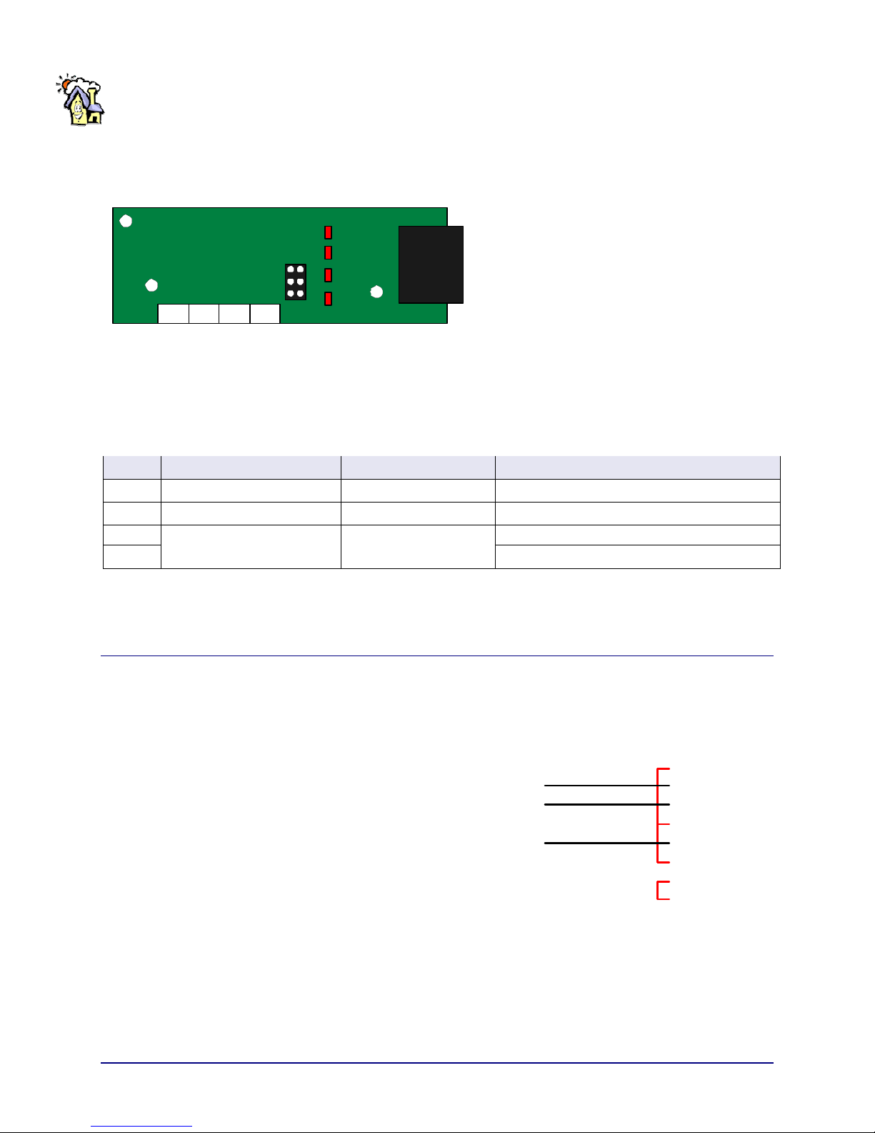
2.1.2 Module connection
DSC PC5401
¾ Connect module to the KEYBUS
− With panel powered down
¾ Select desired BAUD using JP1-3
− Default is 9600 Baud
¾ Connect an RS-232 cable to the application
¾ Power up th e system
RED BLK YEL GRN
DSC Key Bu s
JP1
JP2
JP3
KEYRXTXPWR
Serial
DB9
Figure 1 - PC5401 Board Component
2.1.3 LEDs Indicator
LED Description Normal Operation Notes
KEY KEYBUS Link Active GREEN Solid
PWR Module Status RED Flashing (2 seconds) Solid RED: The module is NOT operating properly
RX
TX
Serial Communication Activity
Flashing when Receive
and transmit data
Table 2 - LEDs Indicator
2.2 Serial Cable
¾ DSC PC5401 Side
− 2 Red (TX)
− 3 Black (RX)
− 5 Yellow (SG)
− 1-4-6-7-8-9 NC
¾ PC (x86) Side
− 1-6-4 Jump (DCD, DSR et DTR)
− 7-8 Jump ensemble (CTS et RTS)
− 9 NC (RI)
− 2 Red (RX)
− 3 Black (TX)
− 5 Yellow (SG)
(NC = No Connect)
PC5401
DB9 - M a le
SG - PI N
DCD - 1
RX - 2
TX - 3
DTR - 4
SG - 5
DSR - 6
RTS - 7
CTS - 8
RI - 9
PC (x86 )
DB9 - Male
PIN - SG
1 - DCD
2 - RX
3 - TX
4 - DTR
5 - SG
6 - DSR
7 - RTS
8 - CTS
9 - RI
Figure 2 - Serial Cable
DSC Alarm PC5401 Serial Module /3
Page 9

3 MISTERHOUSE INTEGRATION
To integrate PC5401 into Misterhouse (MH), first configure properly MH.PRIVATE.INI and begin your
personal code with the following example files.
Copy both in your personal MH code directory (ex.: /mh/code/mycode).
¾ DSC5401.pm: This module is heart of all functions between the DSC Alarm panel and MH, this will
provide DSC status and manage communications.
¾ DSC5401_example.pl: This one his example for your personal code, this had 2 sections.
− The 1
st
section present example code.
− The second example section is web-based event.
¾ DSC5401_web.pl: This will provide a web interface with zone Status, etc. We explain later how to
install this file. For the moment you can copy this file in MH->Web->Bin directory (ex.:
/mh/web/bin)
Some of them are needed to trigger specific event, like thermostat broadcast etc. The card allow mainly
passive event (no user intervention), so it listen to the serial port for information provided by the card.
The module will change state regarding the information receive
3.1 MH.PRIVATE.INI Configuration
There is much information in the mh.private.ini file. These allow getting a better way to display events
information, every zone and user partition.
The mh.private.ini configuration specifications are:
¾ User number need 4 digit to define them "9999"
¾ Zone number need 3 digit "999"
¾ Partition number need 1 digit "9"
¾ 3 parameters are required to tell interface specification configuration and module start-up name
¾ And 5 parameters to tell which information you want to put in the log file.
Description Syntax Option
Module start-up name DSC_5401_module=DSC5401 None
Define which serial port for interfacing PC5401 in MH. DSC_5401_serial_port=/dev/ttyM5
Specify the communication speed. DSC_5401_baudrate=XXXX
DSC Alarm PC5401 Serial Module /4
Page 10

If you enable it, DSC alarm broadcast his time every 4 minutes,
see command table (056) and message table for (550) events.
¾ Note: this Option must be activate, by default is Off
If you have the escort module, it will write in the log when a
phone ring is detected, see message table for (560) event.
If you enable it, DSC Thermostat broadcast his temperature
every 1 minutes
¾ Note: this Option must be activate, by default is Off
DSC_5401_part_log=1 If you want to see partition status (even
when alarm is no on)
DSC_5401_zone_log=1 if you want to see zone status
DSC_5401_time_log=X On/Off (1,0)
DSC_5401_ring_log=X On/Off (1,0)
DSC_5401_temp_log=X On/Off (1,0)
DSC_5401_part_log=X On/Off (1,0)
DSC_5401_zone_log=X On/Off (1,0)
3.1.1 MH.PRIVATE.INI Configuration File Example
Section MH.PRIVATE.INI Parameters
DSC_5401_module=DSC5401
Setup
Options
Partitions
Definition
Users
Definition
Zones
Definition
DSC_5401_serial_port=/dev/ttyM5
DSC_5401_baudrate=9600
DSC_5401_time_log=1
DSC_5401_ring_log=1
DSC_5401_temp_log=1
DSC_5401_part_log=1
DSC_5401_zone_log=1
DSC_5401_part_1=Home
DSC_5401_part_2=Garage
DSC_5401_user_0001=Mary
DSC_5401_user_0003=Tom
DSC_5401_user_0040=MisterHouse
DSC_5401_zone_001=Front Door Contact
DSC_5401_zone_002=Side Door Contact
DSC_5401_zone_003=Upstair Motion Detector
DSC_5401_zone_004= Basement Motion Detector
DSC_5401_zone_005=First Floor Motion Detector
DSC Alarm PC5401 Serial Module /5
Page 11

3.2 DSC Serial Module Perl Library
To enable PC5401.pm file (Generic Function and communication setup) you have to put the following 2
lines in a "MyPersonalNewCode.pl" file.
use DSC5401
$DSC= new DSC5401;
All most information we can get from your example code is:
¾ Zone status
¾ Partition status
¾ Trigger some information broadcast like Time and Temperature (required Escort module and
thermostat)
¾ Arm, Disarm, Alarm and which user
The PC5401.pm modules provide 2 ways to query the panel or zone status. The first (1) is by query a
Functions and the second is by query a Variables. All these are create and maintain up-to-date by this
module.
3.2.1 Functions Values Access
All functions are the most frequently used or important for MH users. When the specific function is used
they will return the element content.
Syntax:
$DSC->function(optional)
Examples:
$DSC->zone_now
$DSC->status_zone(1)
Notes: A function doesn’t use opening and closing brace in command line and the optional
information must pass between opening and closing parenthesis for the syntax format.
DSC Alarm PC5401 Serial Module /6
Page 12

The following tables show all Functions names can be query in your code:
Functions Short Description Result
$DSC->zone_now Return Zone number in the current pass 3
$DSC->zone_now_msg Return message about zone in the current pass Zone Alarm
$DSC->zone_now_status
$DSC->zone_now_open
$DSC->zone_now_restore
$DSC->zone_now_tamper
$DSC->zone_now_tamper_restore
$DSC->zone_now_alarm
$DSC->zone_now_alarm_restore
$DSC->zone_now_fault
$DSC->zone_now_fault_restore
$DSC->zone_name(1..64) Return zone name Kitchen
$DSC->zone_msg(1..64) Return last message about zone number ?
$DSC->status_zone(1..64) Return current zone state Open, Close, etc.
$DSC->partition_now(1..4) ? in the current pass ?
$DSC->partition_now_msg(1..4) ? in the current pass ?
$DSC->partition_name(1..4) Return partition name House
$DSC->user_name Return user name Mary
$DSC->user_id Return user number 0001
$DSC->IntTstat(1..4)
$DSC->ExtTstat(1..4)
$DSC->cmd_list List possible command
Return the current zone state open, close, Alarm, etc.. in
the current pass
Return which zone number in open state, inside the MH
current pass
Return which zone number in restore state, inside the MH
current pass
Return which zone number in tamper state, inside the MH
current pass
Return which zone number in restore state, inside the MH
current pass
Return which zone number in alarm state, inside the MH
current pass
Return which zone number in alarm state, inside the MH
current pass
Return which zone number in alarm state, inside the MH
current pass
Return which zone number in alarm state, inside the MH
current pass
Return the current Internal thermostat temp, the number is
the thermostat number
Return the current External thermostat temp, the number
is the thermostat number
Alarm
3
3
3
3
3
3
3
3
21 F or C
17 F or C
DSC Alarm PC5401 Serial Module /7
Table 3 - MH DSC functions
Page 13

3.2.2 Variables Values Access
A variable can be used to get access to DSC values, which are not available by using a function.
Syntax:
$DSC->{VariableName}{optional}
Examples:
$DSC->{zone_now}
$DSC->{status_zone}{1}
Notes: A DSC variables and its optional information must use with an opening and closing
brace in the command syntax.
The PC5401.pm module working with two (2) types of variables:
¾ The fist, we call then Now_Variables contains actual value before the MH pass is finish.
¾ The second is Status Variables; these will contains the value after the MH Pass is finished.
How it’s work:
¾ $DSC->{zone_now} ==> $DSC->{zone}{3}
¾ $DSC->{zone_now_msg} ==> $DSC->{zone_msg}{3}
¾ $DSC->{zone_now_status} ==> $DSC->{zone_status }{3}
After these variables are reset to Null Value:
¾ Unset $DSC->{zone_now}
¾ Unset $DSC->{zone_now_msg}
¾ Unset $DSC->{zone_now_status}
If you query the Now_Variable in the second pass they will return empty space or nothing, except if something
new append and so fort.
The following tables show all Variables_Names can be query in your code:
Variables Short Description
$DSC->{zone_now}
$DSC ->{zone_now_msg}
$DSC ->{zone_now_status}
$DSC ->{zone_now_alarm}
$DSC ->{zone_now_fault}
$DSC ->{zone_now_fault_restore}
DSC Alarm PC5401 Serial Module /8
Page 14

$DSC ->{zone_now_open}
$DSC ->{zone_now_restore}
$DSC ->{zone_now_tamper}
$DSC >{zone_now_tamper_restore}
$DSC ->{zone_cmd}{1..64}
$DSC ->{zone_msg}{1..64}
$DSC ->{zone_status}{1..64}
$DSC ->{zone_time}{1..64}
$DSC ->{zone_epoch}{1..64}
$DSC ->{partition_now}
$DSC ->{partition_now_cmd}
$DSC ->{partition_now_msg}
$DSC ->{partition_now_mod}
$DSC ->{partition_now_status}
$DSC ->{partition}{1..4}
$DSC ->{partition_cmd}{1..4}
$DSC ->{partition_msg}{1..4}
$DSC ->{partition_status}{1..4}
$DSC ->{partition_time}{1..4}
$DSC ->{partition_epoch}{1..4}
$DSC ->{ring_time}
$DSC ->{ring_epoch}
$DSC ->{ExtTstatTemp_now}
$DSC ->{ExtTstatTemp_now_number}
$DSC ->{IntTstatTemp_now}
$DSC ->{IntTstatTemp_now_number}
3.2.3 Command List and Data Format
Its possible to send a few commands to the DSC alarm the following show the syntax and the table
specify which commands are available.
Syntax:
$DSC->cmd("Command",Send_Value)
Example:
DSC Alarm PC5401 Serial Module /9
Table 4 - MH DSC Variables
Page 15

$DSC->cmd("PartitionArmControl",1)
$DSC->cmd("PartitionArmControlWithCode","1","9999")
(9999 - must be replace by an active Alarm Access Code)
Notes: Is some case the Alarm Access Code must be supply with the desired command.
For more description about all commands refer to DSC PC5401 Developer’s Guide.
Name Number Data Length Data Format
Poll 000 0
StatusReport 001 0
SetDateTime 010 10 hhmmMMDDYY
CommandOutputControl 020 2 ?
PartitionArmControl 030 1 Partition (1-8)
PartitionArmControlStayArm 031 1 Partition (1-8)
PartitionArmControlZeroEntryDelay 032 1 Partition (1-8)
PartitionArmControlWithCode 033 7 Partition (1-8)+Code(6 digit)
PartitionDisarmControl 040 7 Partition (1-8)+Code(6 digit)
VerboseArmingControl 050 1 On/Off (1,0)
TimeStampControl 055 1 On/Off (1,0)
TimeBroadcastControl 056 1 On/Off (1,0)
TemperatureBroadcastControl 057 1 On/Off (1,0)
TriggerPanicAlarm 060 1
CodeSend 200 6 Access Code(6 digit)
Fire (1)
Ambulance (2)
Police (3)
3.3 Perl Programming
3.3.1 Basic Example
Code Example Descriptions
If ( my $ZoneEvent = $DSC->zone_now ) {
print_log "DSC->zone_now $ZoneEvent";
}
DSC Alarm PC5401 Serial Module /10
Table 5 - Command List and Format
This will be trigger the zone status
Page 16

if ( $DSC->zone_now =~ /FrontDoor/ && $DSC>status_zone('012') eq "open" ) {
Speak("Front Door is open");
}
if ( my $PartState = $DSC->partition_now ) {
print_log "DSC->partition_now $PartState";
}
If ( my $AlarmState = $DSC->state_now ) {
print_log "DSC->state_now Alarm system is now
$AlarmState";
}
if ( $DSC->state_now =~ /^disarmed/ && $DSC->user eq
"Mary") {
Speak("Hello Mary");
}
3.3.2 Putting All Together
This will monitor zone 12 for open state and calling an external
voice function.
This will be trigger the Partition status
This will be trigger the Alarm state
This will monitor User Mary when she disarm the panel and
calling an external voice function.
All this files are create in your personal code directory.
3.3.2.1 DSC Start-up Code
# Category=Alarm
#@ Starting DSC Alarm serial module
if ($Startup||$Reload)
{
use DSC5401;
# DSC5401 startup
$DSC = new DSC5401;
}
Filename: DSC5401startup.pl
¾ This code activate the DSC5401.pm
module, wich create all variables, functions
and ensure the DSC Panel communication
with MH.
DSC Alarm PC5401 Serial Module /11
Page 17

3.3.2.2 DSC Zone Monitoring for Lightning Controls
# Category=Alarm
#@ DSCMotion.pl version 1.0,
#@ Motion detection and automatic light controls
#--------------------------------------------------------------------------------------if ($Startup||$Reload) {
print_log "Starting DSC motion module...";
#--- Define Timers Variables
$IR_Room_1_Timer = new Timer();
$IR_Room_2_Timer = new Timer();
# And so one for others timers Creation….
my $State_Light = "";
} #--- End of Reload or Startup
#--------------------------------------------------------------------------------------#-- Start light motion control
if ($Dark eq 1) {
#--- Execute Zone Motion with Light
#--- Room 1
if ($DSC->{zone_status}{10} eq "open") {
$State_Light = state $Light_Room_1;
if ($State_Light eq OFF) {
set $Light_Room_1 -40 if time_between($Time_Sunset,"23:59");
set $Light_Room_1 -50 if time_between("00:00",$Time_Sunrise);
}
if (active $IR_Room_1_Timer) {
unset $IR_Salon_SS_Timer;
}
set $IR_Room_1_Timer 300 if time_between($Time_Sunset,"23:59");
set $IR_Room_1_Timer 200 if time_between("00:00",$Time_Sunrise);
}
# And so one for others Light Controls/Timers….
#--------------------------------------------------------------------------------------#--- Closing Light with when Timeout
if ($New_Minute) {
if (expired $IR_Room_1_Timer) {
set $Light_Room_1 OFF if time_between($Time_Sunset,"19:00");
set $Light_Room_1 if time_between("00:00",$Time_Sunrise);
Filename: DSCmotion.pl
This module will controls your light
in accordance with your alarm
motion detector or door contact.
DSC Alarm PC5401 Serial Module /12
Page 18

}
# And so one for others Timers Expiration/Closing Lights….
} # New minutes for Timers
#--------------------------------------------------------------------------------------} #--- If Dark
3.3.2.3 DSC Panel State Monitoring
# Category=Alarm
#@ This module take care when an alarm situation append
if ($Startup||$Reload) {
print_log "DSC Alarm Controls Statup...";
my $text = "";
my $alarm_previous_state = 0;
}
if ($alarm_previous_state == 0 && $DSC->{partition_status}{1} =~ /alarm/){
print_log "DSC WARNING: $DSC->{partition_status}{1}";
$text = "DSC ALARM, $DSC->{partition_status}{1} in Zone $DSC-
>{zone_now_alarm} $Date_Now $Time_Now";
&alarm_page("$text");
$alarm_previous_state = 1;
}
if ($alarm_previous_state && $DSC->{partition_status}{1} =~ /desarmed/){
print_log "DSC Return State: $DSC->{partition_status}{1}";
$text = "DSC Return State to $DSC->{partition_status}{1} $Date_Now
$Time_Now";
&alarm_page("$text");
$alarm_previous_state = 0;
}
if ($alarm_previous_state && $DSC->{partition_status}{1} =~ /ready/ ){
print_log "DSC Restored: $DSC->{partition_status}{1}";
print_log "---> By: $DSC->{user_name} ($DSC->{user_id})";
$text = "DSC Alarm Restored by $DSC->{user_name} ($DSC->{user_id})
$Date_Now $Time_Now";
&alarm_page("$text");
$alarm_previous_state = 0;
}
if ($DSC->{partition_cmd}{1} >= "800"){
print_log "DSC Healthy Problems....";
$text = "DSC Healty Problems, Please verify... $Date_Now $Time_Now";
Filename: DSC_Alert_Controls.pl
This module can send e-mail to your
working e-mail or on your PCS
phone when an Alarm append or
panel fault is detected.
DSC Alarm PC5401 Serial Module /13
Page 19

&alarm_page("$text");
}
#--# Subroutine to send a page / pcs message, etc.
sub alarm_page {
my ($text2) =@_;
net_mail_send(from => "MyDSCpanel\@MyDomain.org", to =>
"MyWokingEmal or PCS Phome\@ProviderDomain.org",
text => $text2, subject => "DSC(849JP) $DSC->{partition_status}{1}");
speak(mode=>'unmuted', volume=>100, rooms=>'all', text=>"DSC Alarm
Panel Said $text2");
}
3.4 WEB Interface
3.4.1 Configuration
¾ Copy this file DSC5401_web.pl to /usr/local/mh/web/bin
¾ Modify this file /usr/local/mh/web/my_mh/menu.html with the following code:
<base target='output'>
<table height='100%' border='0'>
<tbody>
<td valign='top' align='left' width='100%'>
……
<a href='/bin/DSC5401_web.pl'><img src='/bin/button.pl?DSC Alarm' border='0'></a><br>
</td>
</tbody>
</table>
DSC Alarm PC5401 Serial Module /14
Page 20

3.4.2 DSC WEB Interface
The following DSC Panel Dashboard show:
¾ The top green banner show the panel status
− Green for Ready status
− Orange for Armed status
Y
e
l
l
o
−
ww for Trouble status
Y
e
l
l
o
Y
e
l
l
o
w
− Red for Alarm mode
¾ After the Zones areas
− Green dot for close zone
− Red dot for open zone
− Black dot with grey background for undefined zone in mh.private.ini file.
¾ And command area
− These sections enable you to Arm and Disarm the DSC panel.
¾ The next part presents the alarm activity, which are logs in /mh/data/logs directory.
DSC Alarm PC5401 Serial Module /15
Figure 3 - DSC Web Page
Page 21

Figure 4 - DSC Web log viewer
3.4.3 Modifying MH status line
¾ The following code be integrate in MH status line by mh.private.ini
# Category=Web_Functions
#@ Misc web functions
Filename: web_status_line.pl
# This is called by web/bin/status_line.pl
Copy this file in code directory
# this allow to display DSC information in the status line
# at the bottom of the web page
sub web_status_line
{
my $IntTemp = "-";
my $ExtTemp = "-";
if ($DSC->{IntTstatTemp}{1} eq "")
{
$IntTemp = "(0)";
}
else
{
$IntTemp = $DSC->{IntTstatTemp}{1};
}
if ($DSC->{ExtTstatTemp}{1} eq "")
{
$ExtTemp = "(0)";
}
else
{
$ExtTemp = $DSC->{ExtTstatTemp}{1};
}
DSC Alarm PC5401 Serial Module /16
Page 22

my $html;
$html .= qq[ <img src='/graphics/icons/DSC2.png'
border=0>\n];
$html .= qq[Status:$DSC>{partition_status}{1} <img
src='/ia5/images/temp.gif'
border=0> $IntTemp / $ExtTemp\n];
return $html;
}
¾ Add the line in your mh.private.ini
html_status_line=/bin/status_line.pl?sunrise&sunset&mode&web_status_line&wind&date&jclock2
Figure 5 - DSC Web Status line
¾ The status line shows the panel status and temperature status, when the panel is equipped with a DSC
Escort module and with DSC Thermostat.
3.5 Logs
There is a log file created for every month, which will contains all DSC events.
¾ See ../mh/data/logs
DSC Alarm PC5401 Serial Module /17
Page 23

4 DSC MESSAGES
For more description about all messages refer to DSC PC5401 Developer’s Guide.
Title Number Data Length Data Format
Command Acknowledge 500 3 Last Command Number (999)
Command Error 501 0
System Error 502 3 Error code (000-255)
Time/Date Broadcast 550 10 hhmmMMDDYY
Ring Detected 560 0
Indoor Temperature Broadcast 561 4 Thermostat (1-4)+Temps(999)
Outdoor Temperature Broadcast 562 4 Thermostat (1-4)+Temps(999)
Zone Alarm 601 4 Partition(1-8)+Zone(001-064)
Zone Alarm Restore 602 4 Partition(1-8)+Zone(001-064)
Zone Tamper 603 4 Partition(1-8)+Zone(001-064)
Zone Tamper Restore 604 4 Partition(1-8)+Zone(001-064)
Zone Fault 605 3 Zone(001-064)
Zone Fault Restore 606 3 Zone(001-064)
Zone Open 609 3 Zone(001-064)
Zone Restored 610 3 Zone(001-064)
Duress Alarm 620 4 ?
Fire Key Alarm 621 0
Fire Key Restore 622 0
Auxiliairy Key Alarm 623 0
Auxiliairy Key Restore 624 0
Panic Key Alarm 625 0
Panic Key Restore 626 0
2-Wire Smoke Alarm 631 0
2-Wire Smoke Restore 632 0
Partition Ready 650 1 Partition(1-8)
Partition Not Ready 651 1 Partition(1-8)
Partition Armed 652 2 Partition(1-8)+Mode(0-3)
Partition in Alarm 654 1 Partition(1-8)
Partition Disarmed 655 1 Partition(1-8)
Exit Delay in Progress 656 1 Partition(1-8)
Entry Delay in Progress 657 1 Partition(1-8)
Keypad Lock-Out 658 1 Partition(1-8)
Invalid Code Access 670 1 Partition(1-8)
DSC Alarm PC5401 Serial Module /18
Page 24

Function Not Available 671 1 Partition(1-8)
User Closing 700 5 Partition(1-8)+User(0001-0042)
Special Closing 701 1 Partition(1-8)
Partial Closing 702 1 Partition(1-8)
User Opening 750 5 Partition(1-8)+User(0001-0042)
Special Opening 751 1 Partition(1-8)
Panel Battery Trouble 800 0
Panel Battery Trouble Restore 801 0
Panel AC Trouble 802 0
Panel AC Restore 803 0
System Bell Trouble 806 0
System Bell Trouble Restoral 807 0
TLM Trouble 810 0
TLM Trouble Restore 811 0
TLM Trouble Line 2 812 0
TLM Trouble Restore Line 2 813 0
FTC Trouble 814 0
Buffer Near Full 816 0
Device Low Battery 821 3 Zone(001-064)
Device Low Battery Restore 822 3 Zone(001-064)
Wireless Key Low Battery Trouble 825 3 Key(001-016)
Wireless Key Low Battery Trouble Restore 826 3 Key(001-016)
Handheld Keypad Low Battery Alarm 827 3 HHK(001-004)
Handheld Keypad Low Battery Alarm Restore 828 3 HHK(001-004)
General System Tamper 829 0
General System Tamper Restore 830 0
Home Automation Trouble 831 0
Home Automation Trouble Restore 832 0
Trouble Status 840 1 Partition(1-8)
Trouble Status Restore 841 1 Partition(1-8)
Fire Trouble Alarm 842 0
Fire Trouble Alarm Restore 843 0
Code Required 900 0
Table 6 - DSC Messages Description and Format
DSC Alarm PC5401 Serial Module /19
Page 25

4.1 Error Messages
Number Description
000 No Error
001 RS-232 Receive Buffer Overrun
002 RS-232 Receive Buffer Overflow
003 Keybus Transmit Buffer Overrun
010 Keybus Transmit Buffer Overrun
011 Keybus Transmit Time Timeout
012 Keybus Transmit Mode Timeout
013 Keybus TRansmit Keystring Timeout
014 Keybus Not Fonctionning
015 Keybus Busy (attempting arm or disarm)
016 Keybus Busy - Lockout ( too many disarm)
017 Keybus Busy - Insntallers Mode
020 API Command Syntax Error
021 API Command Partition Error (partition out of bound)
022 API Command Not Supported
023 API System Not Armed
024 API System Not Ready To Arm
025 API Command Invalid Length
026 API User Code not Required
027 API Invalid Characters in Command
Table 7 - Errors Messages Description
DSC Alarm PC5401 Serial Module /20
Page 26

5 RESTRICTIONS
¾ There is no way to manage the X10 or thermostat via Escort Module. I will explain why:
− The 5401 sends and reads information from the keybus.
− Since the X10 and thermostat are processed through the Escort, we cannot send a command
directly.
DSC Alarm PC5401 Serial Module /21
 Loading...