

Page 1
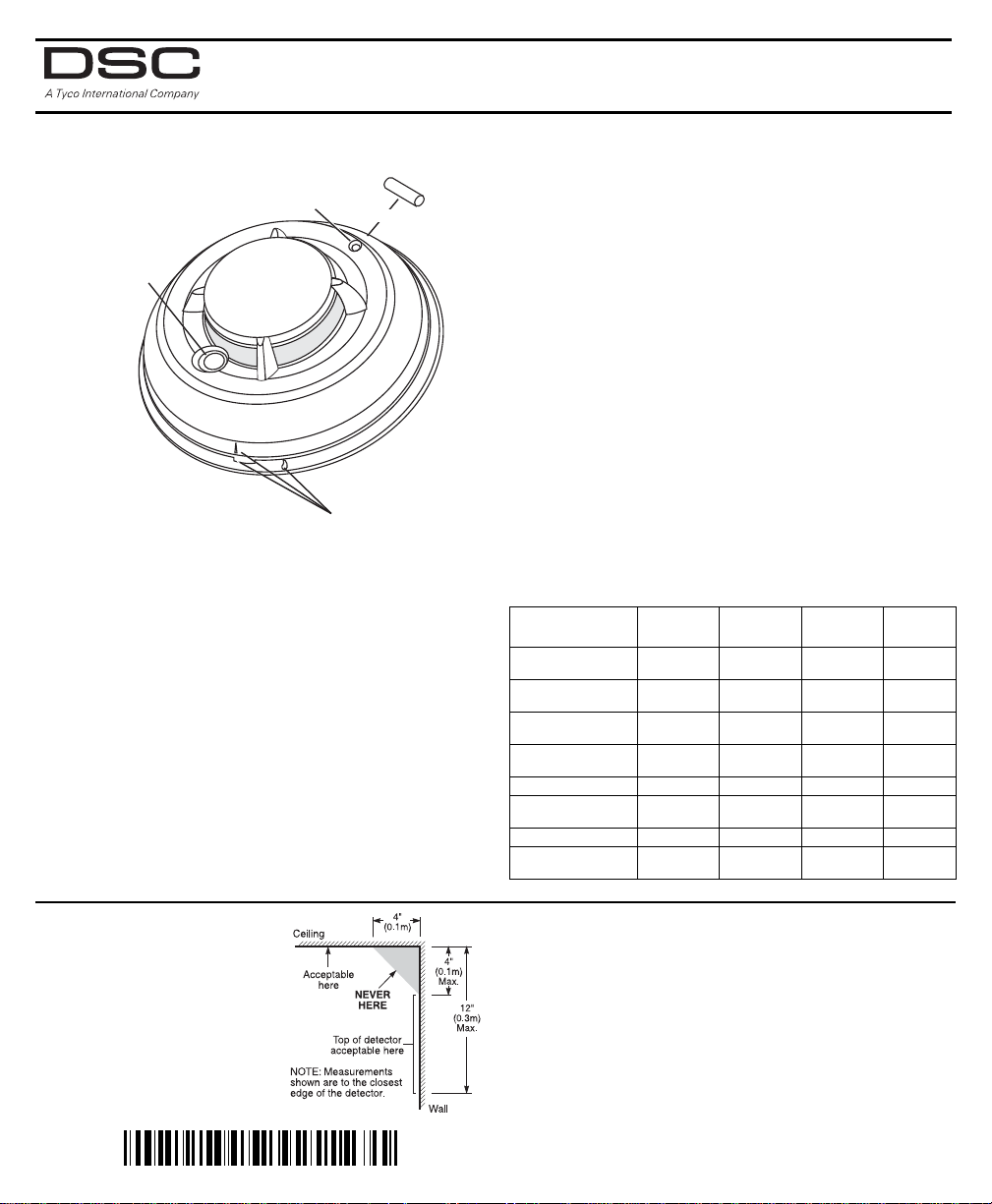
FSA-210 Series Smoke Detector
P P
A A
I I
N N
T T
Piezo Siren
Alignment Marks
LED / Test Button
Place magnet here
DO DO
N N
O O
T T
29006015R007
Installation and Operating Instructions
Read this instruction sheet thoroughly before installation and use of the
FSA-210 2-Wire Smoke Detector. This instruction sheet is intended to be used
with the Installation Manual of the alarm control panel. All the instructions specified within that manual must be observed.
Introduction
The FSA-210 is a 2-wire photoelectric smoke detector with the
following available options: fixed temperature
heat detector, internal piezoelectric alarm, auxiliary form C
relay, and/or remote LED output. Three versions are available:
US version (UL), Canadian version (ULC) and an International
version (EU).
NOTE: Heat detection based on rate of rise has not been
investigated by UL/ULC.
Operation
Approximately every 7 to 8 seconds the unit tests for a smoke
or heat alarm condition. During this sequence the unit also
performs self diagnostics, and checks for faults. During normal
operation the LED will flash every 50 seconds and the siren will
not sound.
Smoke Alarm
The smoke detector has a nominal fixed alarm sensitivity (refer
to the Specifications on the last page) and it will go into alarm
Installer Instructions
1. Smoke Detector Placement
On smooth ceilings, detectors
may be spaced 9.1M (30 feet)
apart as a guide. Other spacing
may be required depending on
ceiling height, air movement, the
presence of joists, uninsulated
ceilings, etc. Consult National Fire
Alarm Code NFPA 72, Chapter 11
CAN/ULC-S553-02 or other
appropriate national standards for
installation recommendations.
and rate of rise
when the signal level exceeds the 'alarm' threshold and send
the alarm signal to the control panel. During an alarm the LED
will flash once per second and the siren will sound the evacuation temporal pattern (UL, EU) or continuous beeps (ULC).
Remote Alarm - Interconnection
Multiple detectors (with sirens) can be connected using the
PRM-2W Polarity Reversal Module. When a fire alarm occurs,
the panel will signal the PRM-2W to reverse the polarity of the
2-wire loop. This will activate the sirens of all units connected
on the loop. Refer to the PRM-2W/4W Installation Instructions
for installation details.
Smoke - Drift Compensation
The detector automatically compensates for long-term environmentally induced changes to maintain a constant smoke
sensitivity. When the drift compensation has reached its high
or low limit of adjustment, the detector will go into the trouble state.
Heat Alarm
The heat detector will go into alarm when the heat signal level
exceeds the heat alarm threshold (135ºF/57ºC); and send the
alarm signal to the control panel. The detector will also go into
heat alarm if there is a rapid increase in the temperature over a
short period of time. During an alarm the LED will flash once
per second and the siren will sound the evacuation temporal
pattern (UL, EU) or continuous beeps (ULC).
Alarm Indications
Condition LED siren Relay
Normal / Sensitivity
in Production Range
Alarm Smoke/Heat Flash 1/1s
Alarm Restore Flash 1/1s
Remote Alarm Flash 1/50s
Low Power Trouble OFF OFF Deactivated No
Other
Fault / Trouble
Test Switch - Failed OFF CHIRP 1/50s Deactivated No
Test Switch - Pass Flash 1/1s
Flash 1/50s OFF Deactivated No
Temporal or
Steady
Temporal or
Steady
Temporal or
Steady
OFF CHIRP 1/50s Deactivated No
Temporal or
Steady
Activated Yes
Activated Yes
Deactivated No
Activated Yes
Alarm
Current
Do NOT locate smoke detectors at the top of peaked or
gabled ceilings; the dead air space in these locations may prevent the unit from detecting smoke. Avoid areas with turbulent
air flow, (near doors, fans or windows). Rapid air movement
around the detector may prevent smoke from entering the
unit. Do NOT locate detectors in areas of high humidity.
Do NOT locate detectors in areas where the temperature rises
above 38ºC (100ºF) or falls below 5ºC (41ºF).
Install smoke detectors in accordance with NFPA 72,
Ch. 11: “Smoke detectors shall be installed outside of each
sleeping area in the immediate vicinity of the bedrooms and
on each additional story of the family living unit, including
basements and excluding crawl spaces and unfinished attics.
Page 2
In new construction, a smoke detector shall also be installed in
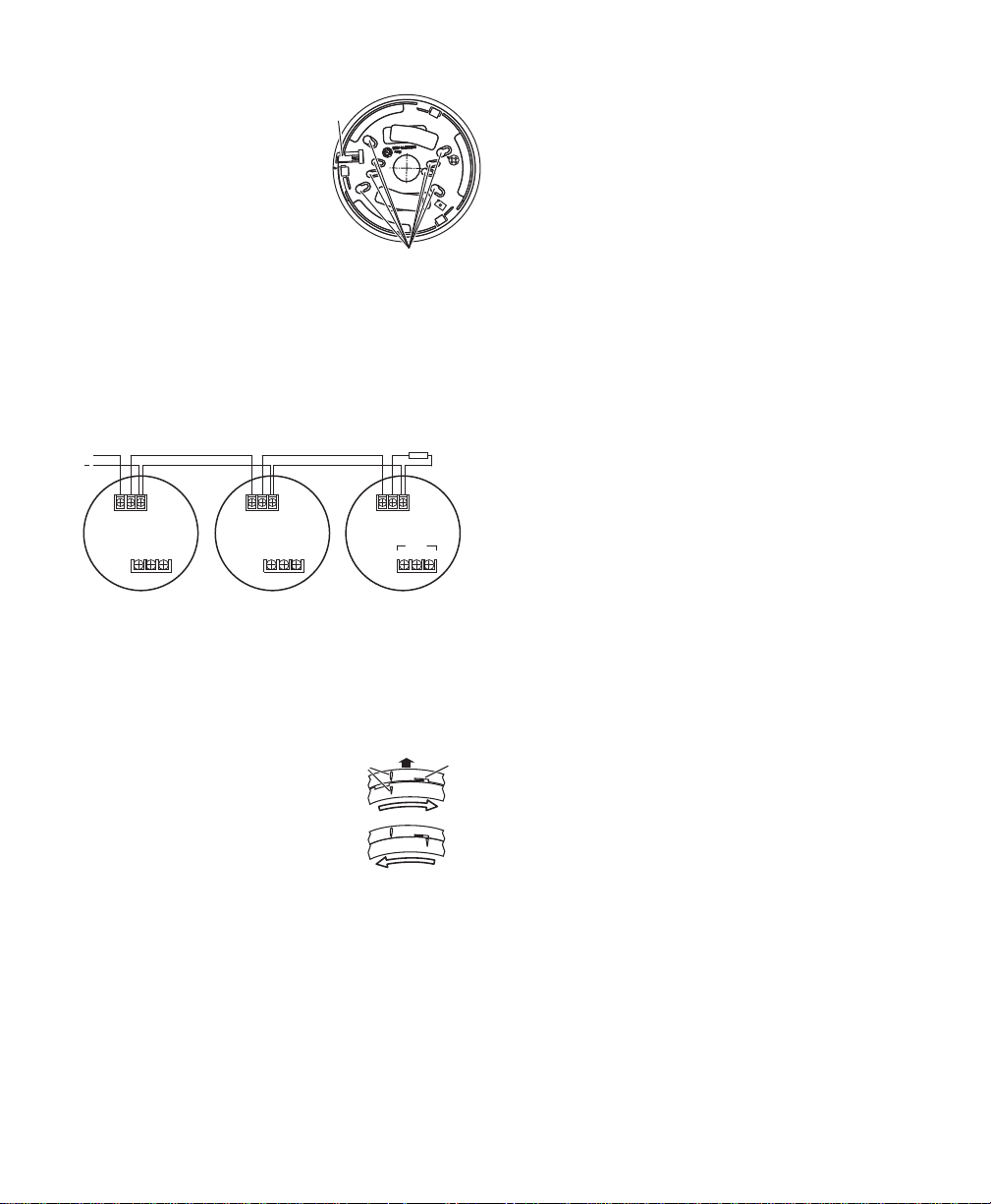
Mounting Holes
Locking
Tab
V+
V
9.35-30VDC
EOL Device
++
-
++
-
++
-
Relay
NO NC C
each sleeping room.”
2. Mount Smoke Detector Backplate
Mount backplate using screws provided and the appropriate holes on
the mounting plate.
NOTE: Install wiring in accordance
with the appropriate national and
local electrical codes. For UL/ULC
Installations, the power supply must
be supplied from a UL/ULC Listed
alarm control unit.
CAUTION: The dust cover protects
the unit when not in service. Remove dust cover before use.
The EU and International versions, shall be powered from an
acceptable to the local authorities alarm controller.
3. Wiring
Refer to the wiring diagrams in this installation sheet and
those provided in the Installation Manual of the alarm control
panel being used with the unit. Before connecting the unit,
prepare the wires from the electrical box for connection; Do
not use frayed or bent wire.
CAUTION: Do NOT use looped wire under terminals. Break
the wire run, to provide supervision of connections.
When wiring is completed, inspect it and correct any errors
before applying power to the unit. When the wiring has been
thoroughly reviewed, neatly insert the wires into the electrical
box and secure the unit to the mounting plate.
To connect this device use only wiring listed as fit for the purpose.
4. Mounting
Detector Installation
Position the detector on to the base
plate using the detector and base plate
alignment marks. Press the detector
Alignment
Marks
Mounting
Surface
Detector
CLOSE
gently in place while rotating the detector clockwise until the detector snaps
into place. Remove the side tab from
the locking tab to lock in place (optional).
Removal: If the side tab is removed to lock the detector,
depress tab with a small flat blade screwdriver and rotate
detector counter-clockwise until the alignment marks line up.
Remove detector.
5. Test Unit
Initiate test for units without a siren by placing a magnet near
the LED/Test Button for greater than 5 seconds. Initiate test for
units with a siren by pressing the test button for greater than 5
seconds.
Alarm activation is indicated by the LED, the siren, and the
alarm reporting to the Control Panel. If the smoke detectors
are inter-connected using model PRM-2W and a detector is
tested, then all detectors will sound. The detector restores to
OPEN
Backplate
Tab s
normal when the test button is released or when the magnet
is removed.
NOTES: Allow a minimum of 20 seconds between test activations.
If the detector is in one of the following states when a test is
initiated; it will not enter an alarm state.
1. Compensation trouble.
2. Failure of heat or smoke detector.
3. Other internal faults that could prevent a smoke or heat
alarm.
NOTE: Smoke sensitivity of installed detectors can be measured without removal or an alarm being generated using the
FSD-100 Smoke Detector Test Meter.
Test Unit with FSD-100 Smoke Detector Test Meter
To test the unit using the FSD-100, set the test meter up to
read devices as per the instructions supplied with the test
instrument. Depress the test button (or place the FSD-100 on
the outside edge of the plastics beside the test button to activate the reed switch on units without siren) on the smoke
detector for 1 second and release.
NOTES: If the test button is held for 5 seconds or longer, an
alarm will be generated. Move the test meter over the center
of the detector, wait until you hear the test meter beep,
remove the unit and the information can be immediately
reviewed. Please see the instructions supplied with the FSD100 Smoke Detector Test Meter for more information.
Perform the tests one at a time. Performing simultaneous tests
on multiple detectors may trigger an alarm at the control
panel.
6. Removing the Chamber for Cleaning
To clean or replace the smoke chamber the detector must be
opened.
1. Press the 3 tabs on the bottom of the detector outward to
release.
2. Remove the bottom portion which contains the PCB and
the chamber.
3. Place thumb and forefinger on the sides of the chamber in
the locations indicated by the arrows on top of the chamber.
4. Squeeze gently inward and pull up and the chamber will
separate.
5. The removable portion can now be replaced or cleaned.
Cleaning can be done using compressed air. Do not use a
cloth as it may leave particles on the inner wall.
6. Replace the new or cleaned chamber by pressing it down
until it snaps into place. Locate and press the backplate
into the housing making sure the 3 locking tabs are
snapped into their locked position.
7. Compensation Reset
Cleaning, replacement of the smoke sensor, or other changes
may change the background signal/noise of the detector; this
requires the drift compensation be reset. Compensation trouble is one of the faults indicated when the LED indicator is OFF
while the siren is chirping.
• Remove power from the unit, then press and hold the test
button for 30 seconds to power down unit.
• Power up unit while pressing the test button.The LED will
flash; when 5 seconds has elapsed. Release the test button
within 1 second after the fifth LED flash.
• The LED will flash every 8 seconds for 1 minute. When the
detector stops flashing test the detector to verify normal
operation.
Page 3

Owner’s Instructions
Fire Safety In The Home
Most fires occur in the home, and to minimize this danger, it is
recommended that a household fire safety audit be conducted and a family escape plan be developed.
Household Fire Safety Audit
1. Are all electrical appliances and outlets in safe condition?
Check for frayed cords, overloaded lighting circuits, etc. If
you are uncertain about the condition of your electrical
appliances or household service, have a professional evaluation.
2. Are all flammable liquids safely stored in closed containers,
and in a cool and well ventilated area? Avoid cleaning the
unit with flammable liquids.
3. Are hazardous materials such as matches out of the reach
of children?
4. Are furnaces and wood burning appliances properly
installed, clean, and in good working order? If in doubt,
have a professional evaluation.
Family Escape Planning
There is often very little time between the detection of a fire
and the time it becomes deadly. Because of this, it is very
important that a family escape plan be developed and
rehearsed.
• Include every family member when developing the escape
plan.
• Study the possible escape routes from each location within
the house. Since many fires occur at night, give special
attention to the escape routes from sleeping quarters.
• It is essential that escape from a bedroom be possible without opening the interior door. Consider the following
when making your escape plans:
• Ensure that doors and windows that open to the outside
are easily opened. Ensure that they are not painted shut
and that the locking mechanisms operate smoothly.
• Develop plans for rescue, if opening the exit or using the
exit is too difficult for children, the elderly or handicapped.
This plan includes making sure that those who are to perform the rescue can promptly hear the fire warning signal.
• If the exit is above the ground level, provide an approved
fire ladder or rope, as well as training in its use.
• Keep exits on the ground level clear. Be sure to remove
snow from exterior patio doors in the winter and that outdoor furniture or equipment does not block exits.
• Have a predetermined assembly point where everyone can
be accounted for; for example, across the street or at a
neighbor’s house.
• Once everyone is out of the house, call the Fire Department.
• A good plan emphasizes a quick escape. Do not investigate first or attempt to fight the fire, and do not attempt
to rescue belongings or valuables as this takes up time.
Once outside, do not re-enter the house; wait for the Fire
Department.
• Write the plan down and rehearse it frequently so that
should an emergency ever arise, everyone will know what
to do. Revise the plan as conditions change; for example,
when there are more or fewer family members in the
home or if there are changes to the house.
• Make sure your fire warning system is operational by conducting weekly tests. If you are unsure about system operation, contact your smoke detector installer or dealer.
• DSC recommends that you contact your local Fire Department and request further information on home fire safety
and escape planning. If available, have your local fire prevention officer conduct an in-house fire safety inspection.
Testing Your Smoke Detector
Follow the test procedure described here or contact your
smoke detector dealer or installer for testing instructions. DSC
recommends that you test the entire alarm system at least
once a week to verify the operation of all system functions.
Units with Siren - Push-button switch
To test the smoke detector, press and hold the test button on
the front of the unit for 5 seconds minimum, the siren initiates
a clicking noise during this time. When the button is pressed,
the unit’s alarm will sound and an alarm will be sent to the
control panel. When the button is released, the alarm will
cease.
Units without Siren - Magnet-activated switch
To test the smoke detector, place a magnet adjacent to the
test button on the front of the unit (see Fig. 1) and hold in
place for a minimum of 5 seconds. When the magnet is in
place, the internal reed switch will activate and an alarm will
be sent to the control panel. When the magnet is removed,
the alarm will cease.
Upon completing the functional testing of the smoke detector, check the unit’s sensing chamber to ensure proper operation. To test the sensing chamber, wave a lit cotton wick or
punk stick around the outside of the unit until a generous
amount of smoke enters the sensing chamber or the unit
alarms. If the smoke detector does not function properly, call
your smoke detector installer or dealer for service.
Maintenance
The smoke detector is designed to require minimum maintenance. If the case becomes dusty, vacuum with a small brush
attachment. If the case is greasy, wipe the case gently with a
soft cloth slightly dampened with soapy water.
Never disassemble the smoke detector; there are no user
serviceable parts inside the unit. Never paint the unit. Paint
may prevent smoke from entering the unit. If you are planning renovations or repainting, contact your installer and
ask that the unit be temporarily removed until work is complete.
If the unit is located in an area where it is exposed to high levels of dust or insects and causes false alarms, it may require
service; contact your smoke detector installer or dealer. Testing
and maintenance procedures shall be in accordance with
CAN/ULC-S552.
Page 4

Smoke Detector Family Specifications
R = A uxilia ry Fo r m C Rel ay
S = Sounder
T = Temperature Sensor
DG009060
FSA-210 X YYY
A = ULC
B = UL
C = EU
2-Wire Smok e Detector F amily
Diameter (base) . . . . . . . . . . . . . . . . . . . . . . . . . . . 5.8in (147mm)
Height (including base) . . . . . . . . . . . . . . . . . . . 2.077in (528mm)
Operating Temperature with Heat Detector . 32º-100ºF (0º-37.8ºC)
Humidity . . . . . . . . . . . . . . . . . . . . 5%-93% RH, non-condensing
Maximum Operating Voltage Range . . . . . . . . . . . . .9.35 - 30V
Maximum Standby Current . . . . . . . . . . . . . . .20μA@12 or 24VDC
Maximum Alarm Current: . . . . . . . . . . . . . . . . . . . . . . . 35-75mA
Smoke Sensitivity ULC . . . . . . . . . . . . . . 2%±0.5%/ft obscuration
Smoke Sensitivity UL . . . . . . . . . . . . . . . 3%±0.8%/ft obscuration
Heat Alarm . . . . . . . . . . . . . . . . . . . . . . . . . . . . . . . . 135ºF (57ºC)
Siren Alarm Pattern UL . . . . . . . . . . . Evacuation Temporal Pattern
LED
Output
Max. Alarm
Model Heat Siren
SA210A, FSA210B, FSA-210C NO NO NO NO 35mA
FSA-210AT, FSA-210BT,
FSA-210CT
FSA-210AR, FSA-210BR,
FSA-210CR
FSA-210ART, FSA-210BRT,
FSA-210CRT
FSA-210AS, FSA-210BS,
FSA-210CS
FSA-210AST, FSA-210BST,
FSA-210CST
FSA-210ARS, FSA-210BRS,
FSA-210CRS
FSA-210ARST, FSA-210BRST,
FSA-210CRST
FCC Compliance Statement
CAUTION: Changes or modifications not expressly approved by DSC could void your
authority to use this equipment.
This equipment has been tested and found to comply with the limits for a Class B digital
device, pursuant to Part 15 of the FCC Rules. These limits are designed to provide reasonable
protection against harmful interference in a residential installation. This equipment generates,
uses and can radiate radio frequency energy and, if not installed and used in accordance with
the instructions, may cause harmful interference to radio communications. However, there is
no guarantee that interference will not occur in a particular installation. If this equipment does
cause harmful interference to radio or television reception, which can be determined by turning the equipment off and on, the user is encouraged to try to correct the interference by one or
more of the following measures:
• Re-orient the receiving antenna.
• Increase the separation between the equipment and receiver.
• Connect the equipment into an outlet on a circuit different from that to which the receiver is
connected.
• Consult the dealer or an experienced radio/television technician for help.
The user may find the following booklet prepared by the FCC useful: “How to Identify and
Resolve Radio/Television Interference Problems”. This booklet is available from the U.S.
Government Printing Office, Washington D.C. 20402, Stock # 004-000-00345-4.
Industry Canada Compliance Statement
This Class B digital apparatus meets all requirements of the Canadian interference-causing
equipment regulations.
Cet appareil numérique de la Classe B respecte toutes les exigences de règlement sur le matériel brouilleur du Canada.
SOFTWARE PRODUCT LICENSE
The SOFTWARE PRODUCT is protected by copyright laws and international copyright treaties, as well as other intellectual property laws and treaties. The SOFTWARE PRODUCT is licensed, not sold.
1. GRANT OF LICENSE This EULA grants You the following rights:
(a) Software Installation and Use - For each license You acquire, You may have only one copy of the SOFTWARE
PRODUCT installed.
(b) Storage/Network Use - The SOFTWARE PRODUCT may not be installed, accessed, displayed, run, shared or used
concurrently on or from different computers, including a workstation, terminal or other digital electronic device
(“Device”). In other words, if You have several workstations, You will have to acquire a license for each workstation where
the SOFTWARE will be used.
(c) Backup Copy - You may make back-up copies of the SOFTWARE PRODUCT, but You may only have one copy per
license installed at any given time. You may use the back-up copy solely for archival purposes. Except as expressly provided in this EULA, You may not otherwise make copies of the SOFTWARE PRODUCT, including the printed materials
accompanying the SOFTWARE.
2. DESCRIPTION OF OTHER RIGHTS AND LIMITATIONS
(a) L imitations on Reverse Engineering, Decompilation and Disassembly - You may not reverse engineer, decompile, or
disassemble the SOFTWARE PRODUCT, except and only to the extent that such activity is expressly permitted by applicable law notwithstanding this limitation. You may not make any changes or modifications to the Software, without the
written permission of an officer of DSC. You may not remove any proprietary notices, marks or labels from the Software
Product. You shall institute reasonable measures to ensure compliance with the terms and conditions of this EULA.
(b) Separation of Components - The SOFTWARE PRODUCT is licensed as a single product. Its component parts may
not be separated for use on more than one HARDWARE unit.
(c) Single INTEGRATED PRODUCT - If You acquired this SOFTWARE with HARDWARE, then the SOFTWARE
PRODUCT is licensed with the HARDWARE as a single integrated product. In this case, the SOFTWARE PRODUCT
may only be used with the HARDWARE as set forth in this EULA..
(d) Rental - You may not rent, lease or lend the SOFTWARE PRODUCT. You may not make it available to others or post
it on a se rver or web sit e.
(e) Software Product Transfer - You may transfer all of Your rights under this EULA only as part of a permanent sale or
transfer of the HARDWARE, provided You retain no copies, You transfer all of the SOFTWARE PRODUCT (including
all component parts, the media and printed materials, any upgrades and this EULA), and provided the recipient agrees to
YES NO NO NO 35mA
NO NO YES NO 50mA
YES NO YES NO 50mA
NO YES NO NO 60mA
YES YES NO NO 60mA
NO YES YES NO 75mA
YES YES YES NO 75mA
©2011 Tyco International Ltd. and its Respective Companies. All Rights Reserved. www.dsc.com
Tech Support: 1-800-387-3630 (Canada & USA) or 905-760-3000
Printed in Czech 17
Aux
Relay
Current
Draw
Siren Alarm Pattern ULC . . . . . . . . . . . . . . . . . .Continuous Beeps
Minimum Remote LED Resistance:
12V system . . . . . . . . . . . . . . . . . . . . . . . . . . . . . . 500 Ohm
24V system . . . . . . . . . . . . . . . . . . . . . . . . . . . . . 1000 Ohm
Maximum Remote LED output (if equipped): . . . . . . . . . . . . 25mA
Auxiliary Relay Rating (Form C Relay) . . . . 2A @ 30V
FSA-210 series compatibility identifier: . . . . . . . . . . . . . . . . FS200
DSC Compatible Control Units:
DSC PC1555 with compatibility identifier: . . . . . . . . PC15-1
DSC PC5010 with compatibility identifier: . . . . . . . . . PC5-1
DSC PC5015 with compatibility identifier: . . . . . . . . PC15-1
DSC PC5020 with compatibility identifier: . . . . . . . . . PC5-2
DSC PC4020 with compatibility identifier: . . . . . . . . . . FM-2
DSC PRM-2W with compatibility identifier: . . . . . . . . .PR200
NOTE: If this detector is used with compatible VISTA series
control panels, set zone de-bounce time at the maximum of
1.2 seconds.
the terms of this EULA. If the SOFTWARE PRODUCT is an upgrade, any transfer must also include all prior versions of
the SOFTWARE PRODUCT.
(f) Termination - Without prejudice to any other rights, DSC may terminate this EULA if You fail to comply with the
terms and conditions of this EULA. In such event, You must destroy all copies of the SOFTWARE PRODUCT and all of
its component parts.
(g) Trademarks - This EULA does not grant You any rights in connection with any trademarks or service marks of DSC or
its suppliers.
3. COPYRIGHT - All title and intellectual property rights in and to the SOFTWARE PRODUCT (including but not limited to any images, photographs, and text incorporated into the SOFTWARE PRODUCT), the accompanying printed
materials, and any copies of the SOFTWARE PRODUCT, are owned by DSC or its suppliers. You may not copy the
printed materials accompanying the SOFTWARE PRODUCT. All title and intellectual property rights in and to the content which may be accessed through use of the SOFTWARE PRODUCT are the property of the respective content owner
and may be protected by applicable copyright or other intellectual property laws and treaties. This EULA grants You no
rights to use such content. All rights not expressly granted under this EULA are reserved by DSC and its suppliers.
4. EXPORT RESTRICTIONS - You agree that You will not export or re-export the SOFTWARE PRODUCT to any
country, person, or entity subject to Canadian export restrictions.
5. CHOICE OF LAW - This Software License Agreement is governed by the laws of the Province of Ontario, Canada.
6. ARBITRATION - All disput es arising in connecti on with this Agree ment shall b e determin ed by final and bindin g
arbitration in accordance with the Arbitration Act, and the parties agree to be bound by the arbitrator’s decision. The place
of arbitration shall be Toronto, Canada, and the language of the arbitration shall be English.
7. LIMITED WARRANTY
(a) NO WARRANTY - DSC PROVIDES THE SOFTWARE “AS IS” WITHOUT WARRANTY. DSC DOES NOT
WARRANT THAT THE SOFTWARE WILL MEET YOUR REQUIREMENTS OR THAT OPERATION OF THE
SOFTWARE WILL BE UNINTERRUPTED OR ERROR-FREE.
(b) CHANGES IN OPERATING ENVIRONMENT - DSC shall not be responsible for problems caused by changes in
the operating characteristics of the HARDWARE, or for problems in the interaction of the SOFTWARE PRODUCT with
non-DSC-SOFTWARE or HARDWARE PRODUCTS.
(c) LIMITATION OF LIABILITY; WARRANTY REFLECTS ALLOCATION OF RISK - IN ANY EVENT, IF ANY
STATUTE IMPLIES WARRANTIES OR CONDITIONS NOT STATED IN THIS LICENSE AGREEMENT, DSC’S
ENTIRE LIABILITY UNDER ANY PROVISION OF THIS LICENSE AGREEMENT SHALL BE LIMITED TO THE
GREATER OF THE AMOUNT ACTUALLY PAID BY YOU TO LICENSE THE SOFTWARE PRODUCT AND
FIVE CANADIAN DOLLARS (CAD$5.00). BECAUSE SOME JURISDICTIONS DO NOT ALLOW THE EXCLUSION OR LIMITATION OF LIABILITY FOR CONSEQUENTIAL OR INCIDENTAL DAMAGES, THE ABOVE
LIMITATION MAY NOT APPLY TO YOU.
(d) DISCLAIMER OF WARRANTIES - THIS WARRANTY CONTAINS THE ENTIRE WARRANTY AND SHALL
BE IN LIEU OF ANY AND ALL OTHER WARRANTIES, WHETHER EXPRESSED OR IMPLIED (INCLUDING
ALL IMPLIED WARRANTIES OF MERCHANTABILITY OR FITNESS FOR A PARTICULAR PURPOSE) AND
OF ALL OTHER OBLIGATIONS OR LIABILITIES ON THE PART OF DSC. DSC MAKES NO OTHER WARRANTIES. DSC NEITHER ASSUMES NOR AUTHORIZES ANY OTHER PERSON PURPORTING TO ACT ON
ITS BEHALF TO MODIFY OR TO CHANGE THIS WARRANTY, NOR TO ASSUME FOR IT ANY OTHER WARRANTY OR LIABILITY CONCERNING THIS SOFTWARE PRODUCT.
(e) EXCLUSIVE REMEDY AND LIMITATION OF WARRANTY - UNDER NO CIRCUMSTANCES SHALL DSC
BE LIABLE FOR ANY SPECIAL, INCIDENTAL, CONSEQUENTIAL OR INDIRECT DAMAGES BASED UPON
BREACH OF WARRANTY, BREACH OF CONTRACT, NEGLIGENCE, STRICT LIABILITY, OR ANY OTHER
LEGAL THEORY. SUCH DAMAGES INCLUDE, BUT ARE NOT LIMITED TO, LOSS OF PROFITS, LOSS OF
THE SOFTWARE PRODUCT OR ANY ASSOCIATED EQUIPMENT, COST OF CAPITAL, COST OF SUBSTITUTE OR REPLACEMENT EQ UIPMENT, FACILITIES OR SERVICES, DOWN TIME, PURCHASERS TI ME,
THE CLAIMS OF THIRD PARTIES, INCLUDING CUSTOMERS, AND INJURY TO PROPERTY. WARNING:
DSC recommends that the entire system be completely tested on a regular basis. However, despite frequent testing, and
due to, but not limited to, criminal tampering or electrical disruption, it is possible for this SOFTWARE PRODUCT to fail
to perform as expected.
1134
DSC, Toronto, Canada
2011
1134-CPD-003
DC
DC (Resistive)
EN54-5/A1 (2002)
EN54-7/A2 (2006)
Point type smoke and
heat detector
 Loading...