

Page 1

PIR/MICROWAVE MOTION DETECTOR
®
F2-201/UK
INSTALLATION
INSTRUCTIONS
FEATURES
• Patented Multi-Level Signal Processing (PIR)
• Digital temperature compensation
• Digital microwave signal processing
• DRO microwave technology for low current and reliable
operation
• Adjustable microwave detection pattern to match room size
• MOV transient / static protection
• High RF immunity with SMD construction
• Exceptional white light immunity
• Microprocessor low voltage protection
• Tamper switch
• Form A alarm contacts
SPECIFICATIONS
ELECTRICAL
Operating Voltage .................................................9.5 to 14.5 VDC
Ripple Tolerance ................................................. 3 VP-P at 12 VDC
Stand-by Current ................................................ 30 mA at 12 VDC
Alarm Current ..................................................... 30 mA at 12 VDC
Alarm Contacts ............................................. Form ‘A’ (standard)
Tamper Contact ............................................................. Standard
Contact Ratings ............................................... 100 mA at 24 VDC
Alarm Contact Series Resistance ............................. 10Ω 0.25W
OPERATION
Coverage (max. length x max. width) ..... 40' × 50' (12m × 15m)
MW Range Adjust ..................................... 10' to 40' (3m to 13m)
Alarm Duration ............................................................ 2 seconds
Walk Speed ......................... 0.5 ft/s to 10 ft/s (0.15m/s to 3.0m/s)
Nominal Mounting Height .......................................... 7.5' (2.3m)
Jumper .............................................................. Alarm LED on/off
IMMUNITY
RF Immunity ...................... 30 V/m over range 0.01 to 1200 MHz
Transients at Terminals .................................2.4 kV at 1.2 joules
Static Discharge Immunity .................................................. 25 kV
White Light ......................................... 20 000 Lux at the detector
Operating Temperature ..................... 32° to 122° F (0° to 50° C)
Humidity .................................... 5% to 95% RH non-condensing
Temperature Compensation .......... Over entire operating range
DESCRIPTION
The Force2 201 is a dual detector employing both microwave
(MW) and passive infrared (PIR) motion sensors. The sensors are
combined through a microprocessor to provide intelligent motion
detection designed to eliminate single detector false alarms.
Significant technical features such as the PIR's Multi-Level Signal
Processing (MLSP), digital temperature compensation, a highly
reliable DRO microwave sensor and digital MW signal analysis
combine for a new level of detection sensitivity, stability and false
alarm immunity.
The PIR and MW systems are each designed as independent, high
quality motion detectors. When combined, the result is a detector
with unmatched performance.
The detector indicates an alarm when both sensors detect motion
within 10 seconds of each other. The first sensor, either the PIR or
MW, which detects motion will start the 10 second confirmation
period during which the other sensor must also detect motion. If
the first sensor’s detection is not confirmed within 10 seconds, the
unit disregards the alarm.
LOCATING THE DETECTOR
Mount the detector in a dry indoor location which will force the
intruder to walk perpendicular to the beam, and allow the beam
pattern to adequately cover the area being protected. Survey the
mounting location and the area being protected for the following
potential problems.
MOUNTING HEIGHT
The Force2 is designed to provide optimum coverage when
mounted between 2.1m (7') to 2.4m (8’) from the floor. If the unit is
mounted above 2.4m (8’), the PIR will have a slightly longer range,
but the “dead” zone directly below the unit will be increased. If the
unit is mounted below 2.1m (7’) the PIR section will have a shorter
range and the “dead” zone directly below the detector will be
decreased.
NOTE: Optimum dual detector detection occurs when the
coverage patterns of the PIR and MW section are matched.
Differences between PIR and MW coverage patterns could
reduce its effectiveness.
REFLECTIVE/METALLIC SURFACES
Do not aim the detector at reflective surfaces or metallic surfaces
that could vibrate. Reflective surfaces could distort the PIR coverage
pattern; vibrating metallic surfaces or rotating fans could be seen
as motion by the MW sensor. Metallic surfaces close to the unit may
reduce MW sensitivity.
AIR FLOW
The Force2 is protected against air flow and airborne
contamination. However, do not locate the detector where it will
be subject to direct high air flow such as fans, hot air vents or open
windows.
CONTAMINATION
Do not locate the detector near a source of oil or water vapour,
such as a steaming kettle or cooking area in a kitchen.
SUNSHINE
The FORCE 2 is resistant to white light but direct sunlight is a high
energy source. Do not locate the detector where it will receive
direct sunlight, particularly in the morning or evening when the sun
is low and may shine in through a window.
TEMPERATURE CHANGES
Do not aim the detector at objects that change temperature rapidly,
such as heaters or ovens.
OBSTRUCTIONS
Do not limit the desired area of protection by placing large objects
such as plants or filing cabinets, so as to obstruct the detector's
coverage pattern.
PETS
Do not aim the detector where pets may trigger either the microwave
or PIR motion sensors. If both sensors are tripped, an alarm will
result.
DISASSEMBLING THE DETECTOR
To open the detector, pull on the front of the detector while pressing
on the release at the bottom of the detector with a small screwdriver.
To remove the circuit board and sensor assembly from the detector
case, press gently on the top of the MW detector until the circuit
board unlocks and slides towards the bottom of the detector.
To replace the circuit board and sensor assembly, place the
circuit board assembly into the detector’s back so that the white
plastic frame fits into the two slots in the detector’s back. Press
gently on the bottom of the MW detector assembly to slide the
circuit board towards the top of the detector. The circuit board
assembly will snap firmly into place.
NOTE: To avoid damage to the detector, do not press against
any of the components on the circuit board when removing and
replacing the board.
PIR / MW BEAM PATTERNS
MIN
MW
ADJUS T
MAX
J1
Page 2
With the circuit board removed, use a small screwdriver to punch
out the wiring and mounting knockouts located in the detector’s
back. Feed the wiring through the wiring knockout and secure the
detector to the wall.
DM-C AND DM-W DETECTOR MOUNTING BRACKETS
Use the optional DM-W wall-mount
and DM-C ceiling mount brackets to
DM-CDM-C
DM-C
DM-CDM-C
Ceiling Mounting BracketCeiling Mounting Bracket
Ceiling Mounting Bracket
Ceiling Mounting BracketCeiling Mounting Bracket
solve difficult placement problems.
The DM-W and DM-C mount to either
the wall or ceiling and allow for full
vertical and horizontal positioning of
the motion detector - the detector can
be tilted up or down and rotated
DM-WDM-W
DM-W
through 90° to obtain the best position
for optimal coverage. The Force2 has
DM-WDM-W
Wall Mounting BracketWall Mounting Bracket
Wall Mounting Bracket
Wall Mounting BracketWall Mounting Bracket
been designed to be fully compatible
with the DM-W and DM-C brackets.
Contact your DSC distributor for more
information.
IMPORTANT NOTE: Maximum
detection coverage occurs when the
Force2 is mounted at the height specified in the mounting
instructions and the mounting surface is vertical. If this cannot
be achieved with a mounting bracket, then detector coverage
may be less than specified.
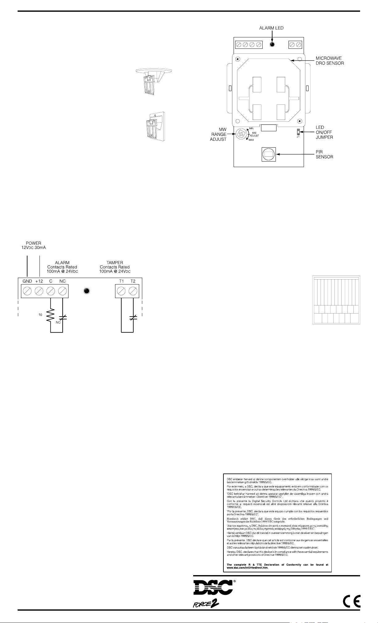
COMPONENT LOCATIONS
WIRING
Once the detector is mounted in the desired location, connect the
wiring as shown below.
NOTE: Contacts are shown in the non-alarm state with power
applied to the detector.
Wiring shall be insulated with PVC, TFE, PTFE, FEP neoprene or
polymide.
Ω
POWER UP
Upon application of power, the alarm indicator will be illuminated
for 60 seconds to indicate the unit is warming up. During this
period, the alarm relay is held in its normal non-alarm state. After
the 60 second warm-up period, the alarm indicator will go out and
the unit will respond to motion in the protected area.
ALARM INDICATOR ON/OFF JUMPER J1
With jumper J1 OFF, the alarm indicator will turn on each time the
unit goes into alarm. With J1 ON, the alarm indicator is disabled.
RANGE ADJUSTMENT
The detector’s range is adjustable from about 10' minimum to 40'
maximum (3m minimum to 13m maximum). Rotating the “MW
Adjust” potentiometer clockwise increases the range; rotating the
potentiometer counter-clockwise decreases the range. For
optimum performance, the range should be adjusted so that it
matches the size of the area to be protected. The unit is factoryset for maximum range.
It is strongly recommended that the range of the detector be
adjusted to match the size of the protected area. To do this, first,
set the LED jumper to the OFF position to enable the LED.
Have someone walk at the farthest spot from the detector that is still
within the desired detection area. Adjust the “Range Adjust”
potentiometer until the alarm LED no longer illuminates when the
person walks through the extreme edge of the detection area.
When so adjusted, readjust the potentiometer so that the unit will
go into alarm when a person walks at the extreme edge of the
detection area.
CAUTION: Microwave frequencies can penetrate walls and
glass. Adjust the range so that it does not extend outside the
desired area of detection.
WALK TESTING
It is imperative that the unit be thoroughly walk tested after mounting
and any necessary adjustment be made to ensure that coverage
extends over the desired area. Refer to the 'Range Adjustment'
section of these instructions.
Once coverage has been confirmed, Jumper J1 may be set to the
ON position to disable the alarm LED indicator.
IMPORTANT NOTE: Upon installation, the unit should be
thoroughly tested to verify proper operation. The end user should
be instructed on how to perform walk tests, and should perform a
walk test at least once per year.
PIR LENS
The PIR lens is mounted with the textured
side facing in (smooth side facing out).
Note that the long lens elements are at the
top when the lens is properly positioned.
Ensure the lens is properly seated, and
that the lens holder is securely snapped
into place.
LIMITED WARRANTY
Digital Security Controls Ltd. warrants that for a period of twelve months from the date of purchase, the product
shall be free of defects in materials and workmanship under normal use and that in fulfilment of any breach of such
warranty, Digital Security Controls Ltd. shall, at its option, repair or replace the defective equipment upon return
of the equipment to its repair depot. This warranty applies only to defects in parts and workmanship and not
to damage incurred in shipping or handling, or damage due to causes beyond the control of Digital Security
Controls Ltd. such as lightning, excessive voltage, mechanical shock, water damage, or damage arising out of
abuse, alteration or improper application of the equipment.
The foregoing warranty shall apply only to the original buyer, and is and shall be in lieu of any and all other
warranties, whether expressed or implied and of all other obligations or liabilities on the part of Digital Security
Controls Ltd. Digital Security Controls Ltd. neither assumes responsibility for, nor authorizes any other person
purporting to act on its behalf to modify or to change this warranty, nor to assume for it any other warranty or
liability concerning this product.
In no event shall Digital Security Controls Ltd. be liable for any direct, indirect or consequential damages, loss
of anticipated profits, loss of time or any other losses incurred by the buyer in connection with the purchase,
installation or operation or failure of this product.
Motion detectors can only detect motion within the designated areas as shown in their respective installation
instructions. They cannot discriminate between intruders and intended occupants. Motion detectors do not
provide volumetric area protection. They have multiple beams of detection and motion can only be detected in
unobstructed areas covered by these beams. They cannot detect motion which occurs behind walls, ceilings,
floor, closed doors, glass partitions, glass doors or windows. Any type of tampering whether intentional or
unintentional such as masking, painting, or spraying of any material on the lenses, mirrors, windows or any
other part of the detection system will impair its proper operation.
Passive infrared motion detectors operate by sensing changes in temperature. However their effectiveness can be
reduced when the ambient temperature rises near or above body temperature or if there are intentional or
unintentional sources of heat in or near the detection area. Some of these heat sources could be heaters, radiators,
stoves, barbeques, fireplaces, sunlight, steam vents, lighting and so on.
WARNING: Digital Security Controls Ltd. recommends that the entire system be completely tested on a
regular basis. However, despite frequent testing, and due to, but not limited to, criminal tampering or
electrical disruption, it is possible for this product to fail to perform as expected.
IMPORTANT INFORMATION
CHANGES OR MODIFICATIONS NOT EXPRESSLY APPROVED BY DIGITAL SECURITY CONTROLS
LTD. COULD VOID THE USER’S AUTHORITY TO OPERATE THIS EQUIPMENT.
TOP
PIR LENS
©2001 Digital Security Controls Ltd.
Toronto, Canada • www.dsc.com
®
is a registered trademark of Digital Security Controls Ltd.
Printed in Canada 29001657 R0 02
 Loading...