

Page 1

Installation Instructions -Encore
The Encore PIR detector is a versatile general purpose PIR designed to provide reliable motion detection for both residential and commercial applications. It provides
effective detection over a large coverage area (50'L x 60'W / 15.2 x 18.3m) while
also providing immunity to such false alarm producing influences as RF, static and
electrical transient. Multi Level Signal Processing (MLSP)*, temperature compensation and the large multi-beam lens design
mean that the human target will not slip by unnoticed - even under challenging conditions. This technology, plus exceptional
design care and careful factory testing, ensures years of trouble free performance. Four interchangeable lenses, wall or corner
mounting, vertical adjustment and swivel mounting bracket provide application versatility .
*Protected by the following patents: Canada 2099971 US 5444432
Locating the Detector
Select a detector location that will provide the coverage required. Consider the following to avoid false alarms:
• Do not aim the detector at reflective surfaces such as mirrors or windows as this may distort the coverage pattern or reflect sun-
light directly onto the detector. Avoid locations that are subject to direct high air flow such as near an air duct outlet.
• Do not locate the detector near sources of moisture such as steam or oil.
• For premises with pets, use the pet alley lens.
• Do not limit the coverage by placing large obstructions in the detection area, such as plants or cabinets.
Installing the Detector
To open the case, use a small flat blade screwdriver and gently push in the tab at the bottom of the case and lift the cover upwards .
Bracket Mounting
Pull back the PCB retaining clip on the right hand side of the housing and lift out the PCB.
Hold the rear housing down on its back on a flat surface. Position the blade of a flat head screwdriver at the mid point of the
groove located between the housing and the swivel knockout. Press down on the screwdriver to pierce the plas tic, then pry upwards
to break off the knockout. Remove any rough edges.
Feed the system wiring through the back of the swivel bracket. Secure the bracket in the desired position. With the bracket firmly
mounted, position the socket of the rear housing over the ball of the bracket. Install the washer over the threaded wire conduit
making sure that the pivot pin of the washer is seated in it's socket on the rear housing. Install the securing nut and tighten just
enough to hold all components together. Re-install and wire up the PCB according to the instructions below. Adjust the orientation
of the housing
and set the vertical adjustment of the PCB to the zero position.
Next, insert and tighten the retaining screw. Then,
tighten the securing nut.
Wall Mounting
If the swivel mount is not being used, use a small screwdriver to remove the appropriate mounting screw and wiring entrance knockouts
from the backplate. Mount the backplate to the wall. Wire up and re-install the PCB according to the instructions below and adjust the
vertical adjustment.
Re-installing the PCB
Position the PCB into the notches along the left hand side of the housing and press the PCB down under the right hand side retainer
clip. Set the vertical adjustment; next insert and tighten the retaining screw provided.
Vertical Adjustment
NOTE: Range and dead zones may vary due to settings.
Using the Mounting Height Chart (see back), set the vertical adjustment for the desired coverage. The height will be indicated by the
gauge located at the bottom left hand corner of the circuit board. Ensure that the PCB retaining screw is tightened just enough to prevent
board movement.
Moving the circuit board down will increase the far range and move the near beams farther out from the mounting wall. Moving the circuit
board up will reduce the far range and bring the near beams closer to the mounting wall. Moving the board down too much will cause the
far beams to "look" above the target. As a result, the range may appear shorter.
Jumpers
There are two jumpers on the detector circuit board. jumper J1 will enable/disable the alarm LED. If J1 is OFF, the LED will not operate on
alarm. If J1 is ON the LED will operate on alarm. Upon power up, if J1 is ON, the LED will turn on for approximately one minute to indicate
the warm-up period. Jumper J2 selects between normal and hostile operation. For a typical environment, the unit should be set to "normal" (J2 ON). If the environment presents potential disturbances which cannot be avoided, set J2 to "hostile" (J2 OFF).
NOTE: When using the corridor lens, set J2 to ON.
Changing Lenses
The detector is supplied with the wall-to-wall lens (BV-L1-UV). To change the lens, release the top tab and pull the lens holder out. This action
releases the lens. Insert the new lens with the GROOVES FACING INWARD. The bottom of the lens is indicated by two triangular indentations.
Ensure that the lens is centered and then reattach the lens holder. The lens holder will snap into place sealing the lens into position.
NOTE: The corridor lens should not be used for corridors less then 6'/1.8m wide. Ensure the beams are aimed directly down
the centre of the corridor.
Walk Testing
IMPORTANT NOTE: Upon installation, the unit should be thoroughly tested to verify proper operation. The detector should be
walk tested weekly by the end user and annually by the installer .
Once the detector has been set up, create motion in the entire area where coverage is desired by walking perpendicular to the lens pattern.
Should the coverage be incomplete, re-adjust or re-locate the detector. Once coverage is as required, the alarm LED may be disabled by
setting J1 to OFF. Always perform a walk test after repositioning the detector.
IMPORTANT NOTE: UL639 requires that the unit be tested at least once per year.
Instructions de montage -Encore
Le détecteur de mouvement infrarouge passif Encore est un PIR versa tile tout usage conçu pour offrir une détection de mouvement
fiable pour les applications résidentielles et commerciales. Il offre une détection efficace sur une large zone de couverture (15,2 x
18,3 m /50' L x 60' l) tout en assurant une excellente protection cont re des influences provoquant des fausses alarmes telles que la
RF, le brouillage et le transitoire électrique. Grâce au traitement de la signalisation multiniveau (Multi Level Signal Processing
(MLSP))*, à la compensation de température et à sa lentille avec une conception multi-faisceaux large, la cible humaine ne pourra
pas passer inaperçue - même dans des conditions difficiles. En plus du soin exceptionnel apporté à la conception et aux essais en
usine, cette technologie assure de nombreuses années de performances sans problème. Quatre lentilles interchangeables, une
installation au mur ou dans un coin, un réglage vertical et un support de montage pivotant offrent une grande souplesse d'emploi.
*Protégé par les brevets suivants: Canada 2099971 US 5444432
Emplacement du détecteur
Choisissez un emplacement qui permette au détecteur de couvrir la zone requise. Tenez compte des éléments suivants pour éviter les fausses
alarmes:
• Ne placez pas le détecteur en face de surfaces réfléchissantes telles que des miroirs ou des fenêtres car elles pourraient
déformer le diagramme de rayonnement ou réfléchir la lumière solaire directement sur le détecteur.
• Évitez les emplacements où le détecteur pourrait être exposé à un courant d'air intense comme une sortie de gaine de circulation d'air.
• Ne placez pas le détecteur près de sources d'humidité telles que de la vapeur d'eau ou d'huile.
• Pour les lieux où des animaux domestiques sont présents, utilisez la lentille allée pour animaux domestiques.
• Ne limitez pas la couverture en plaçant des objets importants dans la zone de détection, comme des plante s ou des armoires.
Installation du détecteur
Pour ouvrir le coffret, utilisez un petit tourne-vis à lame plate, poussez légèrement sur la languette au bas du coffret et levez le couvercle. Dévissez la vis de la carte à circuit imprimé et poussez la carte aussi loin que possible. Tirez la barrette d'arrêt de la carte à circuit
imprimé à droite dans le coffret et retirez la carte à circuit imprimé.
Supports de montage
Mettez la lame du tourne-vis plat au milieu de la fente située entre le coffret et l'alvéole défonçable du pivot. Appuyez sur le
tourne-vis pour percer le plastique puis tirez pour retirer l'alvéole défonçable. Nettoyez les bords rugueux.
Faites passer le câblage d'alimentation derrière le support de soutien pivotant. Fixez le support à la position désirée. Avec le soutien
bien fixé, placez le culot situé au fond du coffret sur la rotule du support. Installez la rondelle sur la gaine de câble filetée en vous
assurant que l'axe de pivotement de la rondelle est placé dans son culot au fond du coffret. Vissez l'écrou de fixation juste assez pour
maintenir tous les composants. Installez la carte à circuit imprimé à nouveau et branchez la conformément aux instructions fournies.
Ajustez l'orientation du coffret et réglez l’ajustement vertical du circuit imprimé à la position zéro. Ensuite insérez la vis de retenue et
serrez-la. Serrez l'écrou de fixation.
Installation au mur
Si le montage à pivot n'est pas utilisé, prenez un petit tourne-vis pour retirer les alvéoles défonçables appropriées des vis de
montage et des entrées de câbles de la plaque arrière. Installez la plaque de montage sur le mur. Rebrancher la carte du circui t
imprimé conformément aux instructions fournies et faites le réglage vertical.
Réinstallation de la carte à circuit imprimé
Placez le circuit imprimé dans les encoches le long du côté gauche du boîtier et poussez le circuit imprimé vers le bas sous l’attache
de retenue sur le côté droit. Réglez l’ajustement vertical; insérez ensuite la vis de retenue et serrez-la.
Réglage vertical
REMARQUE: La portée et des zones mortes peuvent varier selon les milieux.
En utilisant le graphique pour la hauteur du montage (voir au dos), effectuez le réglage vertical pour la couverture désirée. La hauteur sera
indiquée sur le calibre situé au coin gauche inférieur de la carte à circuit imprimé. Assurez-vous que la vis de fixation de la carte à circuit
imprimé est assez serrée pour empêcher tout mouvement de la carte. Un déplacement vers le bas de la carte à circuit imprimé augmen te
la portée distale et éloigne les faisceaux avant du mur de montage. Un déplacement vers le haut de la carte à circuit imprimé réduit la
portée distale et rapproche les faisceaux avant du mur de montage. Si la carte est trop déplacée vers le bas les faisceaux « verront » audessus de la cible. Par conséquent la portée pourra paraître plus courte.
Barrettes
Il y a deux barrettes sur la carte à circuit imprimé du détecteur. La barrette J1 activera/désactivera l'alarme DEL. Si J1 est à ARRÊT, le
DEL ne fonctionnera pas en alarme. Si J1 est à MARCHE le DEL fonctionnera en alarme. Lors de la mise sous tension, si J1 est à
MARCHE, le DEL s'allumera pour approximativement une minute pour indiquer une période de réchauffement. La barrette J2 permet de
choisir entre un fonctionnement en milieu normal et un fonctionnement en milieu hostile. Pour un milieu ordinaire, l'unité devrait être
réglée à « normal » (J2 MARCHE). Si le milieu offre des perturbations potentielles qui ne peuvent pas être évitées, réglez J2 à « hostile
» (J2 ARRÊT). REMARQUE: Si vous utilisez la lentille couloir, réglez J2 sur MARCHE.
Changement de lentille
Le détecteur est fourni avec la lentille mur à mur (BV-L1-UV). Pour changer la lentille, soulevez la languette supérieure et retirez le
porte-lentille. Cette action libère la lentille Insérez la nouvelle lentille avec les RAINURES VERS L'INTÉRIEUR. Le bas de la lentille est
indiquée par deux empreintes triangulaires. Assurez-vous que la lentille est centrée et rattachez le porte-lentille. Le porte-lentille sera
remis en place par simple pression fixant la lentille en position. REMARQUE: La lentille couloir, ne doit pas être utilisée pour les
couloirs de moins de 1,8 m (6' pieds) de largeur. Assurez-vous que les faisceaux visent directement le milieu du couloir.
Essai de marche
REMARQUE IMPORTANTE: Lors de l'installation, le détecteur devra avoir subi un essai complet pour vérifier que tout fonctionne
correctement. Le détecteur devrait être inspecté une fois par semaine par l' utilisateur et annuellement par l'installateur.
Une fois le détecteur installé, créez des mouvements dans toute la zone où la couverture est désirée en marchant perpendiculairement à
la configuration de détection de la lentille. Si la couverture est incomplète, effectuez un réglage ou déplacez le détecteur. Une fois que
la couverture est bonne, l'alarme DEL peut être désactivée en mettant J1 à ARRÊT. Effectuez toujours un essai de marche après avoir
changé la position du détecteur.
REMARQUE IMPORTANTE: La mention UL-639 indique que l'installation doit être vérifiée au moins une fois par année.
Instrucciones de Instalación - Encore
El detector Encore PIR es un PIR de propósitos versátiles y generales diseñado para proporcionar una detección confiable de movimiento
para aplicaciones comerciales y residenciales. Proporciona una detección efectiva sobre una extensa area de cubrimiento (50'L x 60'A /
15,2 x 18,3 m) mientras también proporciona inmunidad contra tales influencias que producen alarmas falsas como FR, estática y
transitorios eléctricos. Procesamiento de Señal de Nivel Múltiple (MLSP)* y el diseño de lente grande de múltiples haces significan que
el objetivo humano no pasará inadvertido - inclusive bajc condiciones desafiantes. Esta tecnología, además del cuidado del excepcional
diseño y las cuidadosas pruebas de fabricación, le aseguran años libres de fallas en el funcionamiento. Cuatro lentes intercambiables,
montaje en pared o esquina, ajustamiento vertical y placa de montaje giratoria proporcionan una versatilidad en la aplicación.
*Protegido por las siguientes patentes: Canadá 2099971 US 5444432
Localización del Detector
Seleccione una localización para el detector que proporcione el cubrimiento requerido. Considere lo siguiente para evitar alarmas falsas:
• No dirija el detector hacia superficies reflectantes tales como espejos o ventanas ya que esto puede distorsionar el patrón de
cubrimiento o reflejar la luz solar directamente al detector.
• Evite ubicaciones que están sujetas directamente a una corriente alta de aire tales como cerca a un conducto de aire.
• No coloque el detector cerca origenes de humedad como vapor o aceite.
• Para estructuras con mascotas, use el lente "pet alley". No limite el cubrimiento por grandes obstrucciones en el área de detección tales como plantas o armarios.
Instalación del Detector Encore
Para abrir la cubierta, use un destornillador de hoja recta pequeña y cuidadosamente empuje hacia adentro la lengüeta en la parte
inferior de la cubierta y levante la cubierta hacia arriba . Afloje el tornillo de PCB y deslice el tablero hacia abajo hasta que sea posible.
Tire hacia atrás el borne de retención PCB localizado al lado derecho de la caja y levante el PCB.
Montaje con Plaqueta
Coloque la hoja del destornillador de hoja recta al punto medio de la ranura colocada entre la cubierta y el prepunzonado de
giratorio. Presione con el destornillador para penetrar el plástico y luego levántelo para remover el prepunzonado. Despeje cualquier borde desigual. Alimente el cableado del sistema por la parte posterior de la plaqueta giratoria. Asegure la plaqueta en la
posición deseada. Con la plaqueta montada firmemente, coloque el manguito de la cubierta posterior sobre la rótula de la
plaqueta. Instale la arandela sobre el conducto roscado del cable, asegurando que el pe rno pivote de la arandela esté sentado
en su manguito en la cubierta posterior. Instale la tuerca de aseguramiento y apriéte la solamente lo suficiente para tener todos
los componentes juntos. Re-instale y conecte el cableado al PCB de acuerdo a las instrucciones provistas.
Ajuste la orientación de
la caja en tal manera que el detector no está apuntado bajo y fije el ajustamiento vertical en el PCB a "0". Inserte y apriete el tornillo de retención.
Montaje en Pared
Si el montaje giratorio no está siendo usado, use un destornillador pequeño para remover los prepunzonados apropiados para los
tornillos de montaje y las entradas del cableado desde la placa posterior. Instale la placa posterior a la pared.
Vuelva a conectar el
circuito impreso de acuerdo a las instrucciones provistas efectue el ajuste vertical
.
Re-instalar el PCB
Coloque el tablero de circuito (PCB) en las muescas al lado izquierdo de la cubierta y presione hacia abajo el PCB debajo del clip de
retención del lado derecho. Fije el ajuste vertical; después inserte y apriete el tornillo de retención.
Ajustamiento Vertical
Nota: El alcance y zonas muertas pueden variar debido a los ajustes.
Usando el Cuadro de Altura de Montaje, fije el ajustamiento vertical para el cubrimiento deseado. La altura será indicada por el calibrador
localizado en la esquina izquierda en la parte inferior del tablero del circuito. Asegúrese que los tornillos de retención PCB estén ajustados
solamente lo suficiente para prevenir un movimiento del t ablero. Moviendo el tablero del circuito hacia abajo aumentará el alcance lejano y
moverá los haces cercanos más afuera de la pared de montaje. Moviendo el tablero del circuito hacia arriba reducirá el alcance lejano y
traerá los haces cercanos más cerca a la pared de montaje. Moviendo el tablero del circuito demasiado hacia abajo causará que los haces
lejanos "miren" por encima del objetivo. Como resultado, el alcance puede aparecer más corto.
Puentes
Hay dos puentes en el tablero del circuito del detector. Puente J1 habilitará/inhabilitará el LED de alarma. Si J1 está fuera de lugar, el
LED no operará en alarma. Si J1 está puesto, el LED operará en alarma. En el momento de encender, si J1 está puesto, El LED se
encenderá por aproximadamente un minuto para indicar el periodo de calentamiento. El Puente J2 selecciona la operación entre normal y desfavorable. Para un ambiente típico, la unidad debe estar fijada para "normal" (J2 puesto). Si el ambiente presenta disturbios
potenciales los cuales no pueden ser evitados, fije J2 para "desfavorable" (J2 fuera de lugar).
NOTA: Cuando está usando el lente corredor, fije J2 para puesto.
Cambiar Lente
El detector es suministrado con lente pared-a-pared (BV-L1-UV). Para cambiar el lente, libere la lengüeta superior y tire hacia afuera el
porta lente. Esta acción libera el lente. Inserte el nuevo lente con LAS RANURAS HACIA ADENTRO. La parte inferior del lente está
indicada por dos muescas triangulares. Asegúrese que el lente esté centrado y después vuelva a acoplarlo al porta lente. El porta lente
enganchará en su lugar sellando el lente en su posición. NOTA: El lente corredor no debe ser usado para corredores con menos
de 6'/1.8m de ancho. Asegúrese que los haces estén dirigidos directamente hacia el centro del corredor.
Prueba de Paso
NOTA IMPORTANTE: En el momento de la instalación, la unidad debe estar completamente probada para verificar una operación correcta. El detector debe ser inspeccionado semanalmente por el usuario final y anualmente por el instalador.
Una vez que el detector ha sido fijado, ocasione un movimiento en toda la área donde el cubrimiento es deseado por medio de caminar
perpendicular al patrón del lente. Si el cubrimiento está incompleto, vuelva a ajustar y a localizar el detector. Una vez que el
cubrimiento está como es requerido, el LED de alarma puede ser inhabilitada por medio de fijar el J1 para fuera de lugar.
Siempre realice una prueba de paso después de haber cambiado la posición del detector.
NOTA IMPORTANTE: UL-639 indica que la instalación debe ser probada al menos una vez al año.
Page 2
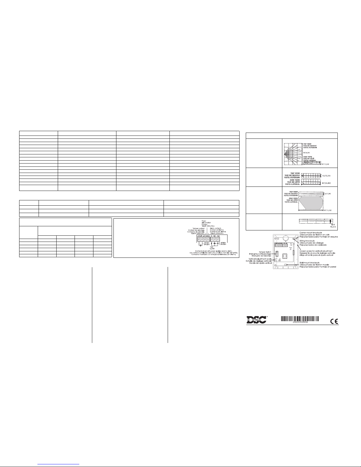
Coverage / Couverture / Cubrimiento
BV-L1-UV
Wall-to-Wall Lens (Standard)
Lentille mur à mur (Standard)
Lente de Pared a Pared (Normal)
50' × 60' (15.2 × 18.3m)
BV-L2-UV
Corridor lens (optional)
Lentille couloir (optionnelle)
Lente Corredor (opcional)
80' × 10.5' (24.4 × 3.2m)
BV-L3-UV
Curtain lens (optional)
Lentille rideau (optionnelle)
Lente Cortina (opcional)
50' × 4.4' (15.2 × 1.3m)
BV-L4-UV
Pet Alley lens (optional)
Lentille passage pour animaux
(optionnelle)
Lente para animales (opcional)
50' × 60' (15.2 ×18.3m)
Models Modèles Modelos
EC-300 Form ‘A’ alarm contacts Contacts d'alarme en forme de 'A' Contactos de alarma Forma 'A'
EC-301 Form ‘A’ alarm contacts & tamper switch Contacts d'alarme en forme de 'A' et interrupteur antisabotage Contactos de alarma Forma 'A' & interruptor de sabotaje
EC-302 Form ‘C’ alarm contacts & tamper switch Contacts d'alarme en forme de "C" et interrupteur antisabotage Contactos de alarma Forma 'C' & interruptor de sabotaje
Limited Warranty
Digital Security Controls Ltd. warrants that for a period of 12 m onths from the date of purchase, the product
shall be free of defects in materials and workmanship under normal use and that in fulfilment of any breach
of such warranty, Digital Security Controls Ltd. shall, at its option, repair or replace the defective equipment
upon return of the equipment to its repair depot. This warranty applies only to defects in parts and workmanship and not to damage incurred in shipping or handling, or damage due to causes beyond the control of
Digital Security Controls Ltd. such as lightning, excessive voltage, mechanical shock, water damage, or
damage arising out of abuse, alteration or improper application of the equipment.
The foregoing warranty shall apply only to the original buyer, and is and shall be in lieu of any and all
other warranties, whether expressed or implied and of all other obligations or liabilities on the part of Digital Security Controls Ltd. Digital Security Controls Ltd. neither assumes responsibility for, nor authorizes any other person purporting to act on its behalf to modify or to change this warranty, nor to assume
for it any other warranty or liability concerning this product.
In no event shall Digital Security Controls Ltd. be liable for any direct, indirect or consequential damages,
loss of anticipated profits, loss of time or any other losses incurred by the buyer in connection with the
purchase, installation or operation or failure of this product.
Motion detectors can only detect motion within the designated areas as shown in their respective installation instructions. They cannot discriminate between intruders and intended occupants. Motion detectors
do not provide volumetric area protection. They have multiple beams of detection and motion can only be
detected in unobstructed areas covered by these beams. They cannot detect motion which occurs behind
walls, ceilings, floor, closed doors, glass partitions, glass doors or windows. Any type of tampering
whether intentional or unintentional such as masking, painting, or spraying of any material on the lenses,
mirrors, windows or any other part of the detection system will impair its proper operation.
Passive infrared motion detectors operate by sensing changes in temperature. However their effectiveness
can be reduced when the ambient temperature rises near or above body temperature or if there are intentional
or unintentional sources of heat in or near the detection area. Some of these heat sources could be heaters,
radiators, stoves, barbeques, fireplaces, sunlight, steam vents, lighting and so on.
WARNING: Digital Security Controls Ltd. recommends that the entire system be completely tested on a
regular basis. However, despite frequent testing, and due to, but not limited to, criminal tampering or electrical disruption, it is possible for this product to fail to perform as expected.
IMPORTANT INFORMATION: Changes or modifications not expressly approved by Digital Security
Controls Ltd. could void the user’s authority to operate this equipment.
Garantie limitée
Digital Security Controls Ltée., pendant une période de douze mois à partir de la date d’achat, garantit le produit
contre toute défectuosité matérielle et d’assemblage dans des conditions normales d’utilisation. Dans l’application de cette garantie, Digital Security Controls Ltée. va, lorsqu’elle le juge opportun, en cas de problèmes de
fonctionnement, réparer ou remplacer les équipements défectueux dès leur retour à son dépôt de réparation.
Cette garantie s’applique seulement aux éléments défectueux et à la main-d’oeuvre, et non aux dommages
causés lors de l’expédition ou de la manipulation, ni aux dommages dont les causes dépassent le contrôle de
Digital Security Controls Ltée. telles que la foudre, les surtensions, les chocs mécaniques, les dégâts d’eau ou
tout dommage provenant d’abus, de modifications ou de mauvaises utilisations de l’équipement.
La garantie susdite n’est valide que pour l’acheteur original et n’est et ne sera que la seule des garanties valables, qu’elle ait été exprimée ou implicite, remplaçant toute autre obligation ou responsabilité de la part de
Digital Security Controls Ltée. La présente garantie contient la garantie au complet. Digital Security Controls Ltée. n’autorise aucune autre personne à agir en son nom pour modifier ou changer la présente garantie
et n’en assume pas la responsabilité, ni a à assumer en son nom toute autre garantie ou responsabilité concernant le présent produit.
En aucun cas, Digital Security Controls Ltée. ne pourra être tenue responsable des conséquences directes ou
indirectes de dommages relativement à la perte de profits prévus, à la perte de temps ou à toute autre perte subie
par l’acheteur en rapport avec l’achat, l’installation et le fonctionnement ou la défaillance du présent produit.
Les détecteurs de mouvement ne peuvent détecter le mouvement que dans les zones désignées, conformément aux instructions d’installation. Ils ne peuvent pas distinguer entre intrus et occupants. Les détecteurs de
mouvement ne fournissent pas de protection de zone volumétrique. Ils ont de multiples rayons de détection et
les mouvements ne peuvent être détectés que dans des zones non obstruées et couvertes par ces rayons. Ils ne
peuvent détecter les mouvements qui se produisent derrière les murs, plafonds, sol, portes fermées, cloisons
vitrées, portes vitrées ou fenêtres. Tout type de problème qu’il soit intentionnel ou non tels camouflage, peinture ou vaporisation de matériel sur les lentilles, miroirs, fenêtres ou toute autre partie du système de détection l’empêchera de son fonctionner normalement.
Les détecteurs de mouvement à infrarouge passif fonctionnent en détectant les changements de température.
Cependant leur fonctionnement peut être inhibé quand la température ambiante s’approche ou dépasse la
température du corps ou s’il y a des sources de chaleur intentionnelles ou non intentionnelles dans la zone de
détection ou à côté de celle-ci. Quelques-unes de ces sources de chaleur peuvent être chauffages, radiateurs,
fours, barbecues, cheminées, lumière du soleil, éclairages, etc .
AVERTISSEMENT : Digital Security Controls Ltée. recommande que le système soit régulièrement soumis à un essai complet. Cependant, en dépit d’essais réguliers et à cause d’interventions criminelles, pannes
de courant ou autres, il est possible que le fonctionnement du produit ne soit pas conforme aux spécifications.
INFORMATION IMPORTANTE: Tout changement ou modification qui n’est pas expressément approuvé
par Digital Security Controls Ltd. pourrait annuler le droit d’usage de cet équipement.
Garantía Limitada
Digital Security Controls Ltd. garantiza que por un período de doce meses desde la fecha de adquisición, el producto estará libre de defectos en materiales y mano de obra bajo condiciones de uso normal y que, en cumplimiento de cualquier violación de dicha garantía, Digita l Security Controls Ltd., podrá, a su opción, reparar o
reemplazar el equipo defectuoso al recibo del equipo en su local de servicio. Esta garantía se aplica solamente a
defectos en componentes y mano de obra y no a los daños que puedan haberse presentado durante el transporte y
manipulación o a daños debidos a causas fuera del control de Digital Security Controls Ltd. tales como rayos,
voltaje excesivo, sacudidas mecánicas, daños por agua, o daños resultados por abuso, alteración o aplicación inadecuada del equipo.
La garantía anterior se aplicará solamente al comprador original y sustituye a cualquier otra garantía, ya sea
explícita o implícita, y todas las otras obliga ciones y responsabilidades por parte de Digital Security Controls Ltd.
Esta garantía contiene la garantía total. Digital Secu rity Controls Ltd. no se compromete, ni autoriza a ninguna
otra persona que pretenda actuar a su nombre, a modificar o cambiar esta garantía ni a asumir ninguna otra
garantía o responsabilidad con respecto a este producto.
En ningún caso, Digital Security Controls Ltd. será responsable de cualquier daño o perjuicio directo, indirecto o
consecuente, pérdidas de utilidades esperadas, pérdidas de tiempo o cualquier otra pérdida in currida por el comprador con relación a la adquisición, instalación, op eración o fallo de este producto.
Los detectores de movimiento solamente pueden detectar movimiento den tro de las áreas designadas como se
muestra en las respectivas instrucciones de instalación. Los detectores de movimiento no pueden discriminar
entre intrusos y los que habitan el local o residencia. Los detectores de movimiento no proporcionan un área de
protección volumétrica. Estos poseen múltiples rayos de detección y el movimiento solamente puede ser
detectado en áreas no obstruidas que están cubiertas por e stos rayos. Ellos no pueden detectar movimiento que
ocurre detrás de las paredes, cielo rasos, pisos, puertas cerr adas, separaciones de vidrio, puertas o ventanas de vid rio. Cualquier clase de sabotaje ya sea intencional o sin intención tales como encubrimiento, pintando o regando
cualquier tipo de material en los lentes, espejos, ventanas o cualquier otra parte del sistema de detecc ión perjudicará su correcta operación.
Los detectores de movimiento pasivos infrarrojos operan detectando cambios en la temperatura. Sin embargo su
efectividad puede ser reducida cuando la temperatura del ambiente aumenta o disminuye de la temperatura del
cuerpo o si hay orígenes intencionales o sin intención de calor en o cerca del área de detección. Algunos de los
orígenes de calor pueden ser calentadores, radiadores, estufas, asadores, chimeneas, luz solar, ventiladores de
vapor, alumbrado y así sucesivamente.
ADVERTENCIA: Digital Security Controls Ltd. recomienda que el sistema sea probado en su integridad con
la debida regularidad. Sin embargo, a pesar de pruebas frecuentes y debido a interferencia criminal o cortes eléctricos, pero no sólo limitado a ellos, es posible que este producto deje de operar en la forma esperada.
INFORMACIÓN IMPORTANTE: Los cambios o modificaciones no aprobadas expresamente por Digital
Security Controls Ltd., pueden cancelar la autoridad del usuario para operar este equipo.
* UL tests only the 85% RH non-cond. / UL teste seultment d’HR non-cond. à 85% / UL prueba solo la humedad relativa no condensada con. indice ** RF immunity was not tested by UL / L’immunité aux radio fréquences n’a pas été vérifiée par UL / La inmunidad a la Ra dio Frquencia no ha sido probada por UL.
Note: The unit shall be provided with 4 hours (min) of standby power from either a compatible control unit or power supply. Note: Cette unité doit être alimentée par un panneau compatible ou un bloc d’alimentation homologué muni d’une alimentation de secours d’une durée d’au moins quatre heures. Nota: La unidad
debe tener cuatro horas mínimo de energía de reserva desde una unidad de control com patible homologada o un suministro de energía homologado.
Specifications Spécifications
Especificaciones
Operating voltage Tension d’opération Voltaje de Operación 9.5VDC-14.5VDC / 9.5VCC-14.5V
CC
Supply voltage ripple Ondulation de la tension d’alim. Tensión de ondulación del suministro de voltaje 3.0V pp @ 12VDC / 3.0V pp @ 12V
CC
Standby current Courant au repos Corriente de espera (Nominal) 16mA
Current in alarm Courant en alarme Corriente en alarma (Nominal) 20mA
Contact rating Courant nominal des contacts Porcentaje de contactos (alarma y sabotaje) 100mA @ 24V
DC
/ 100mA @24V
CC
Alarm contact resistor in common Résistance de contact d’alarme de la ligne commune Resistencia de contactos de alarma en común 10Ω0.25W
Operating temp. Température d’opération Temperatura para Operar 0°C-50°C (32°F-122°F)
Storage temp. Température d’entreposage Temperatura para Guardar -40° C-60°C (40°F-140°F)
Operating humidity Humidité en opération Humedad para Operar 5-95% RH non cond. / d’HR non-cond. / HR no condensada *
Storage humidity Humidité en entreposage Humedad para Guardar up to 99% RH non cond. / d’HR non-cond. / HR no condensada
RF immunity Immunité aux radiofréquences Inmunidad RF 10 V/m with 80% AM from 80MHz-1GHz **
Static immunity Immunité à l’électricité statique Inmunidad de Estática 8kV contact, 15kV air / / 8kV contacto, 15kV aire
Transient immunity Immunité aux courants transitoires Inmunidad Transitoria 2.4kV @ 1.2 joules
Walk detection speed Vitesse de détection de marche Velocidad de detección de paso 0.5-10'/s (0.15-3m/s)
Coverage angle (BV-LI-UV) Couverture angulaire (BV-LI-UV) Angulo de Cobertura (BV-LI-UV) 90° minimum
Vertical Adjustment Réglages verticaux Ajustamientos verticales +5° to -10°
Mounting Heights Hauteurs de montage Altura de montaje 6-10.5'/1.8-3.2m (nominal 7.5'/2.3m) BV-L1, L2, L3-UV
4-5'/1.2-1.5m BV-L4-UV
Mounting Height Chart
Tableau de la portée en fonction de la hauteur d’installation
Tabla de la Altura de Montaje
Height
Hauteur
Altura
Setting for Full Range
Ajustement pour rendement maximale
Ajusta para un Rango Total
BV-L1-UV BV-L2-UV BV-L3-UV BV-L4-UV
10’(3m) *0.00 – 0.00 –
8’(2.4m) +0.50 +0.25 0.00 –
7’(2.1m) +0.75 +0.25 0.00 –
6’(1.8m) +1.00 +0.50 0.00 –
5’(1.5m) – – – 0.00
4’(1.2m) – – – 0.00
©2003 Digital Security Controls Ltd., Toronto, Canada
Tech: 1-800-387-3630 (U.S. & Canada) • 905-760-3036 •
www.dsc.com
Printed in Canada 29005050 R006
Wiring/Câblage/Instalación
NOTE: This unit is UL-639/ULC-S306-M89 Listed and should be connected to a listed control unit or
power supply providing at least 4 hours of standby power.
NOTE: Ce dispositif est homologué UL-639/ULC-S306-M89 et doit être connecté à un panneau de contrôle
ou à une alimentation homologuée fournissant au moins 4 heures d’alimentation de secours.
NOTA: Esta unidad está homologada por UL-639/ULC-S306-M89 y debe ser conectada a un control o a un
suministro de energía homologado proporcionando al menos 4 horas de energía en reserva.
*Factory Setting / Configuration d'Usine / Adjuste de Fábrica
These settings are valid when the detector is positioned perpendicular to the floor. Rotating the detector on the swivel m ount will affect the range / Ces réglages sont valides lorsque le détecteur est perpendiculaire au sol. L'orientation du détecteur
à l'aide du support pivotant affecte sa portée / Est os ajustes son válidos cuando el detector es colocado perpendi cular al piso. Rotar el detector en el montaje giratorio afectará el alcance.
FCC COMPLIANCE STATEMENT
CAUTION: Changes or modifications not expressly approved by Digital Security Controls Ltd. could void your authority to use
this equipment.
This equipment generates and uses radio frequency energy and if not installed and used properly, in strict accordance with the
manufacturer’s instructions, may cause interference to radio and television reception. It has be en type tested and found to comply
with the limits for Class B device in accordance with the specifications in Subpart “B” of Part 15 of FCC Rule s, which are
designed to provide reasonable protection against such interference in any residential installation. However, there is no guarantee
that interference will not occur in a particular installation. If this equipment does cause interference to television or radio recep tion, which can be determined by turning the equipment off and on, the user is encouraged to try to co rrect the interference by
one or more of the following measures:
• Re-orient the receiving antenna
• Relocate the alarm control with respec t to the receiver
• Move the alarm control away from the rece iver
• Connect the alarm control into a different outlet so that alarm control and receiver are on different circuits.
If necessary, the user should consult the dealer or an experienced radio/television technician for additional suggestio ns. The user
may find the following booklet prepared by the FCC helpful: “How to Identify and Resolve Ra dio/Television Interference Problems”. This booklet is available from the U.S. Government Printing Office, Washington, D.C. 20402, Stock # 004-000-00345-4.
Direct all comments concerning this
publication to
pubs@dscltd.com
 Loading...