

DSC EMS-100 Installation Manual
Property of Monitronics Dallas, TX
EMS-100 Thermostat
EMS-100 THERMOSTAT INSTALLATION
General Description
The EMS-100 Thermostat (Enerstat Thermostat) offers user-friendly
control of th e heati ng/cool ing sy stem. It also has an ea sy-to-r ea d vertical LCD that displays complete operation status. A direct wire,
easy-to-install backplate mounts on a standard vertical outlet box or
any drywall surface using anchors and hardware provided.
Specifications
Rated Voltage................... 20-30 VAC
Rated AC.......................... 0.05-0.75 A continuous/output (surges to 3.00 A, max.)
Rated DC @ ‘R’.................0.00-0.75 A continuous/output (surges to 3.00 A, max. )
Control range:Heating...... 5-30°C in (1° steps); or 38-88°F (in 1° steps)
Cooling....... 16-40°C in (1° steps); or 60-108°F (in 1° steps)
Measurement range.........0-48°C; or 28-124°F
ODT Measurement range.–40-48°C; or –40-124°F
Control accuracy.............. ±0.5°C, at 20°C; or ±1°F, at 68°F
Minimum deadband......... (between heating and cooling) 1°C; or 2°F
NOTE: this thermostat contains electronic circuitry that replaces the
conventional mechanical antici pa to r.
Location
For accurate temp eratu r e det ectio n, the rmostat s sho uld be moun ted
on an inside wall (46 cm or 18” from any out side wall ) in a fr equently
occupied a rea with free ly circulat ing air. It should be approximat ely
1.5 m (5’) abov e fl oor. Avoid direct sunlig ht, radi ant heat from a ppl i-
ances, air conditioner grills, stairwells, water pipes, warm air stacks,
and sources of elec trica l interfer e nce su ch as ar ci ng r ela y conta ct s.
Installation
1. Lift thermostat cover and insert flat blade screwdriver or coin,
approx. 3 mm (1/ 8”) into th e slot loc ated in botto m centr e of c ase.
T wist ¼ turn to pop the thermostat loose from its backplate.
2. Swing thermostat from bottom (hinge at top), raise from backplate, and remove from hinge tabs. Place the backplate’s rectangular opening over control panel wires protruding from the wall.
Use backplate as a template to mark location of two mounting
holes.
3. Use supplied anchors and screws for mounting. Drill two 5 mm
(3/16”) mounting holes . Tap nylon anchors flush to wall a nd fa sten backplate with screws.
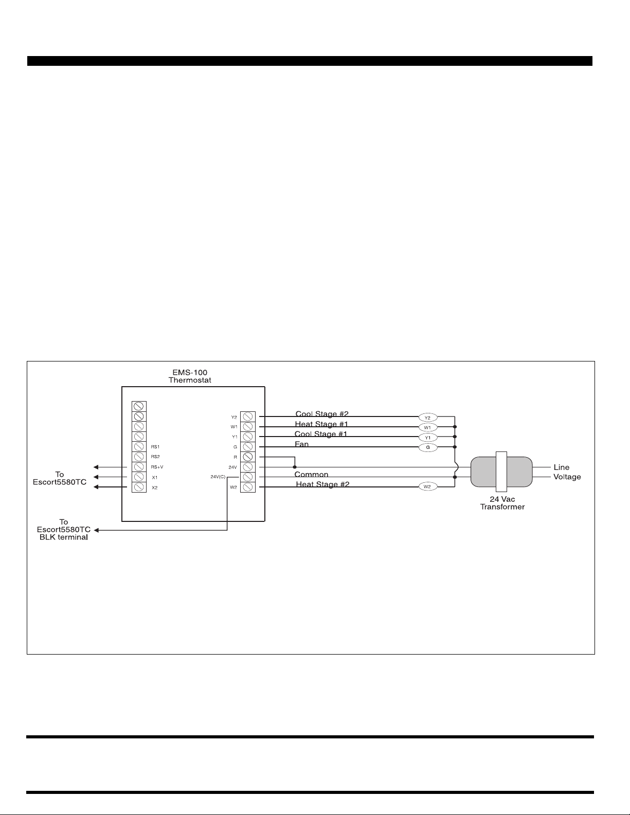
4. Connect control panel wires to thermostat as shown in wiring
diagram. Push any slack wire back into wall. Dress remaining
wires to make them flush with backplate. Seal or stuff access
hole to prevent drafts through wall from affecting thermostat’s
performance.
5. Install optio nal setba ck, in door /outdoo r r emote s ens ors, if used.
6. Replace thermostat to backplate by inserting its top into backplate’s hinge tabs, swinging downwar d and sn app ing bac k i nto
place.
Output Terminal Functions
RS2 ........................... .... ..To Outdoor/Indoor remote sensors.
RS1 ........................... .... ..To Outdoor/Indoor remote sensors.
RS+V...............................To Escort5580TC.
X2....................................To Escort5580TC.
X1....................................To Escort5580TC.
Y2....................................Energizes on a call for second stage cool.
W1............. ...... ........ ....... .Energizes on a call for first stage heat.
Y1.......................... ......... .Energizes on a call for first stage cool.
G............... ........ ............. .Fan is energized with a call for heating or
R ........................... ......... .Independent switching voltage.
AC.............................24 VAC Hot from equipment transform er.
24 V
AC (C) . .. ........ ........ ....2 4 VAC Common from equipment transformer.
24 V
W2...................................Energizes on a call for second stage heat.
cooling or selected by fan button.
OPERATING INSTRUCTIONS
The thermostat normally displays room temperature, mode of operation (i.e. Day or Night), and whether Cooling or Heating is currently
on. The six buttons on the front of the unit allow complete control of
the thermostat. The user may specify different Heating and Cooling
setpoints, and c ha ng e th em ea si ly by pus h in g a bu tton. Temperature
can be displayed in either C or F. The thermostat also allows the
user to select either continuous fan operation, or fan operation only
during operation of the heating/cooling device(s).
• W A R N I N G •
This sheet contains information on limitations regarding product use and function and information on the limita-
tions as to liability of the manufacturer.

Property of Monitronics Dallas, TX
Modes
Select the desi r ed m ode o f oper ation by to ggli ng thr ou gh th em wit h
the MODE button :
❄
—controls Cooling syste m on ly (the word COOL is di sp layed fo r
5 seconds).
—controls Heating syste m only (th e wor d HEAT is displayed for 5
seconds).
❄
—controls bo th th e Heat and Cool s yst ems (th e wor d AUT O i s
displayed for 5 seconds).
❄
(flashing)—indicates Cool ON.
(flashing)—indicates Heat ON.
OFF—disables th ermosta t so it will no t operate .
Cooling:
❄
Select the temperature you want the thermostat to maintain
while in the Cool mode by pressing and holding the or
buttons. The control setpoint temperature is displayed for 5
seconds.
Heating:
Select the temperature you want the thermostat to maintain
while in the Heat mode by pressing and holding the or
buttons. The control setpoint temperature is displayed for 5
seconds.
Fan:
The Fan will come on automatically when the system is operating, but there is no indication of this on the display. To
select continuous Fan operation, press the FAN button and
the display will show . This is recommended for electronic
air cleaners and continuous ventilation requirements.
OFF:
When the word “OFF” is displayed, the thermostat will not
operate.
CAUTION: Avoid using the OFF mode during extremely cold
weather to prevent damage to equipment from freezing.
Auto:
❄
Selecting this mode of operation will control both Heating
and Cooling devices. The thermostat will automatically
switch from one to the other as determined by the selected
setpoints in heating and cooling.
NOTE: The thermostat will not allow less than 1 C (2 F) difference
between the he at ing and cooling s e tpo in ts .
Outdoor (ODT) Button
When the outdoor temperature sensor option is connected to your
thermostat, you can display the current outdoor temperature by
pressing the button. If this option is not connected, the thermostat
will display _ _ with no numbers.
Day/Night Button
When the thermo stat is initially instal led, the display will sho w the
symbol for your Day t emperature. By pressing the Day/Nig ht
button you may select the Night temperature where the display will
show the symbol. This button can be used to toggle between
Day and Night modes. Within each mode the temperature can be
modified. The the rmost at will r e mem ber any new set tings .
Celsius/Fahre nhei t
Simultaneousl y pres s and to tog gle betwee n Celsiu s ( C) and
Fahrenheit ( F) temperature display.
Remote Sensor (Option—RS1, RS2, RS+V)
The thermostat is desi gned to acce pt th e El ectronic Remote Sensor
(indoor or ou tdoor) so that tem per atur es r emot e fr om the thermos tat
can be monitored. Indoor sensors increase the flexibility of where
the thermostat itself can be located. Indoor/outdoor sensors are
available separately.
Temperature Accuracy
Full accuracy is only achieved after the thermostat has been
installed and powered for at least one hou r.
Power Failures
No battery is required to maintain the temperature setpoints in the
case of a power loss, regardless of duration.
LIMITED WARRANTY
Digital Security Controls Ltd. warrants that for a period of twelve months from
the date of purchase, the product shall be free of defects in material and workmanship under norm al use and that in fulfilment of any breach of such warranty, Digital Security Controls Ltd. shall, at its option, repair or replace the defective
equipment upon return of the equipment to its repair depot. This warranty applies
only to defects in parts and workmanship and not to damage incurred in shipping
or handling, o r damage due to causes beyond control of Digital Security Controls
Ltd. such as lightning, excessive voltage, mechanical shock, water damage, or
damage aris i ng o u t of abuse, alteration or improper ap plication of the equipment.
The foregoing war ra nt y shall apply only to t he o rig ina l bu yer, and i s a nd shall be
in lieu of any and all other warranties, whether express or implied and of all other
obligations or liabilities on the part of Digital Securi ty Controls Ltd. This warranty contains the entire warranty. Digital Security Controls Ltd. neither assumes,
FCC COMPLIANCE STATEMENT
CAUTION: Changes or modifications not expressly approved by Digital Security
Controls Ltd. could void your authority to use this equipment.
This equipment generates and uses radio frequ ency energy and if no t installed and
used properly, in strict accordance with the manufacturer’s instructions, may cause
interference to radio and television reception. It has been type tested and found to
comply with the limits for Class B device in accordance with the specifications in
Subpart “B” of Part 15 of FCC Rules, which are designed to provide reasonable protection against such interference in any residential installation. However, there is no
guarantee that interference will not occur in a particular installation. If this equipment does cause interference to television or radio reception, which can be determined by turning the equipment off and on, the user is encouraged to try to correct
the interference by one or more of the following measures:
nor authorizes any other person purportin g to act on its behalf to m odify or to
change this warranty, nor to assume for it any other warranty or liability concerning this product.
In no event shall Digital Security Controls Ltd. be liable for any direct, indirect or
consequential damages, loss of anticipated profits, loss of time or any other losses
incurred by the buyer in connection with the purchase, installation or operation or
failure of this product.
WARNING: DSC Ltd. recommends that the ent ire system be completely tested
on a regular basis. However, despite frequent testing, and due to but not limited to,
criminal tampering or electrical disruption, it is possible for this product to fail to
perform as expected.
•Re-orient the receiving antenna
•Relocate the alarm control with respect to the receiver
•Move the alarm control away from the receiver
•Connect the alarm control into a different outlet so that alarm control and receiver
are on different circuits.
If necessary, the user should consult the dealer or an experienced radio/television
technician for additional suggestions. The user may find the following booklet prepared by the FCC helpful : “How to Identify a nd Resolv e Radio/Television Interference Problems”. This booklet is available from the U.S. Government Printing Of fice,
Washington, D.C. 20402, Stock # 004-000-00345-4.
© 1998 Digital Se cu ri ty Con trols Ltd.
1645 Flint Road , Do wns v ie w, Ontario, Canada M3J 2J6
Tel. (416) 665-8460 • Fax (416) 665-7498 • 1-800-387-3630
Printed in Canada 29003 016 R0
 Loading...