

Page 1
C24-CAM54IR
Quick Installation Sheet
Package Contents
The following items should be included: If any of
these items are damaged or missing, please contact
your distributor immediately.
• C24-CAM54IR
• Stand
• Black Y-cable
• DC cable
• Ethernet cable
• Quick Installation Guide
• 12V 1A Power Adapter
Model C24-CAM54IR
Dimensions
72mm (W) x 72mm (H) x 20mm (D)
(without stand)
Operating
Temperature
-20° C to 45° C
Note: Camera must be brought online
above 0°C.
Video
compression
H.264, MPEG4 and MJPEG
Network
Interface
1 Ethernet 10/100BaseT (RJ45)
Storage
Temperature
-20° C to 60° C
LEDs 3
Power Adapter
12V/1A
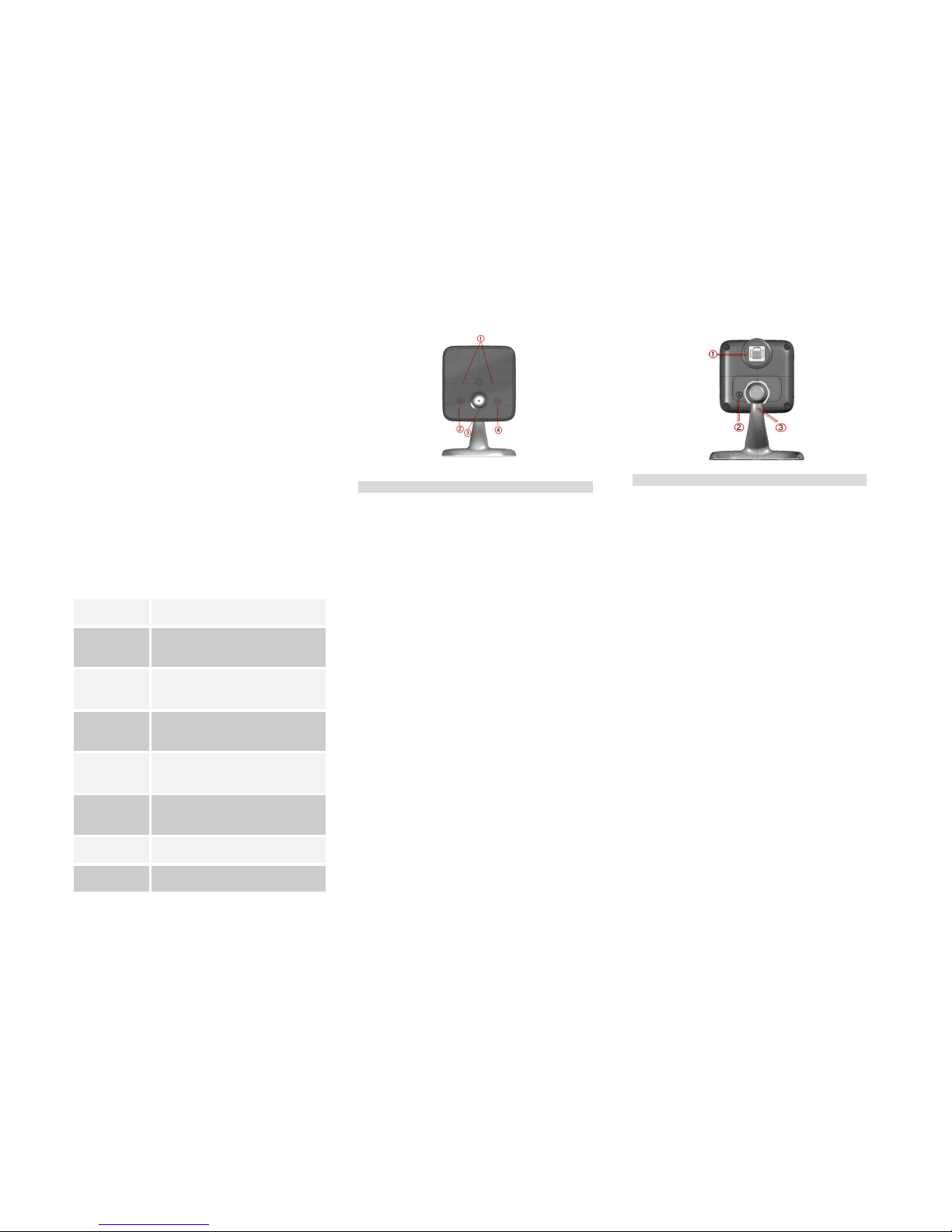
Front - C24-CAM54IR
1. IR LED
The LEDs can help you see clearly even at
night or in the dark environment.
2.
Network
(Green)
• On (Green)- LAN/Wireless
connection established.
• Off - No active connection on the
corresponding LAN port, or not
associated to Wireless AP
• Flashing - Data is being transmitted
or received.
3.
POWER/
WiFi
(Green)
• On (Green)- Power On
• Off - Power Off
• Blinking - Data is being transmitted
or received.
• Blinking Low - Weak strength of WiFi
signal (1/2 Hz, SNR < 15 dB)
• Blinking Medium - Strength of WiFi
signal is normal (1/2 Hz, SNR < 15 dB)
• Blinking High - Good strength of WiFi
signal (1/2 Hz, SNR < 15 dB)
4. WPS
(Green)
• On - When the WPS function is
failed, the WPS LED will be lit on for
5 seconds.
• Off - WPS function is off.
• Flashing - WPS function is being
processed. If it is successful, the
WPS LED will be off.
Rear - C24-CAM54IR
1. LAN Port
Use a standard
LAN cable (RJ45 connectors) and
the customized Power over Ethernet (PoE)
adapter to enrol the camera on the device port of
the C24-HUB.
2. Reset
This button has two (2) functions:
• Reboot. When pressed and released, the
C24-CAM54IR will reboot (restart).
• Clear All Data. This button can also be used
to clear ALL data and restore ALL settings to
the factory default values.
To Clear All Data and restore the factory default
values:
1. Power On.
2. Press and hold the Reset Button for 15
seconds.
3. Release the Reset Button. DO NOT POWER
DOWN until the network LED is lit.
The C24-CAM54IR is now using the factory default
values.
3. Microphone
The built
-
in microphone is useful for bi
-
direction
voice conversation.
Page 2

Installation
Step 1 - Initial Setup
Initial setup is required when the C24-CAM54IR is used for
the FIRST time with a C24-HUB. This initial setup will
enrol and also configure the camera for private WiFi
operation.
1. Assemble the Camera
a. Hold the metal screw of the stand up.
b. Thread the back of the C24-CAM54IR to the
stand and turn the C24-CAM54IR clockwise to
attach it to the stand.
2. Connect the Y-cable
Connect the provided Y-cable (with Ethernet) to the
LAN port of C24-CAM54IR.
The LAN interface is required for initial configuration. After
initial programming, the y-cable can be swapped for the DC
cable for WiFi operation.
3. Connect the Camera to the C24-HUB
Use the supplied Ethernet cable to connect the
Y-cable Ethernet port to the Device LAN port of
C24-HUB.
4. Power Up the Camera
Connect the supplied power adapter to the Y-cable
and power up. Use only the power adapter provided.
Using a different one may cause hardware damage.
5. Check the LEDs
• The Power LED will turn on briefly, then start
blinking. It will blink during startup, which takes 15 to
20 seconds. After startup is completed, the Power
LED should remain ON.
• The Network LED should be ON.
Step 2 - Adding the Camera to an account
1. Log into User Portal (with authorized credentials)
2. Go to the System Tab
3. Click on the “Add Devices” button
4. Click on “Cameras”
5. Select C24-CAM54IR
6. Enter the MAC Address on the back of the camera
7. Click on “Continue”
8. Wait while the System adds your camera
9. Click on “Finish” to complete the installation.
Regulatory Approvals
FCC Statement
This equipment generates, uses and can radiate radio frequency energy and, if
not installed and used in accordance with the instructions, may cause harmful
interference to radio communications. However, there is no guarantee that
interference will not occur in a particular installation. If this equipment does
cause harmful interference to radio or television reception, which can be
determined by turning the equipment off and on, the user is encouraged to
try to correct the interference by one of the following measures:
Reorient or relocate the receiving antenna.
• Increase the separation between the equipment and receiver.
• Connect the equipment into an outlet on a circuit different from that
to which the receiver is connected.
• Consult the dealer or an experienced radio/TV technician for help.
To assure continued compliance, any changes or modifications not expressly
approved by the party responsible for compliance could void the user's
authority to operate this equipment. (Example - use only shielded interface
cables when connecting to computer or peripheral devices).
FCC Radiation Exposure Statement
This equipment complies with FCC RF radiation exposure limits set forth for an
uncontrolled environment. This equipment should be installed and operated
with a minimum distance of 20 centimetres between the radiator and your
body.
This device complies with Part 15 of the FCC Rules. Operation is subject to the
following two conditions:
(1) This device may not cause harmful interference, and
(2) This device must accept any interference received, including interference
that may cause undesired operation.
This transmitter must not be co-located or operating in conjunction with any
other antenna or transmitter.
CE Approvals
The C24-CAM54IR and the Ethernet C24-CAM54IR meet the guidelines of the
European Union and comply with the 99/5/EEC and RTTE 99/5EG directives,
including the following standards:
• EN60950
• EN300 328-2
• EN301 489-1
• EN301 489-17
This is a Class B product. In a domestic environment this product may cause
radio interference in which case the user may be required to take adequate
measures.
This product is UL and cUL certified and comply with UL60950-1 Information
Technology Equipment applicable requirement.
IC Approval
This product complies with Canadian ICES-003 Class B and RSS-210.
Limited Warranty
Digital Security Controls Ltd. warrants that for a period of twelve months from
the date of purchase, the products shall be free of defects in materials and
workmanship under normal use and that in fulfilment of any breach of such
warranty, Digital Security Controls Ltd. Shall, at its option, repair or replace the
defective equipment upon return of the equipment to its factory. This
warranty applies only to defects in parts and workmanship and not to damage
incurred in shipping or handling, or damage due to causes beyond the control
of Digital Security Controls Ltd. Such as lightning, excessive voltage,
mechanical shock, water damage, or damage arising out of abuse, alteration
or improper application of the equipment.
This foregoing warranty shall apply only to the original buyer, and is and shall
be in lieu of any and all other warranties, whether expressed or implied and of
all other obligations or liabilities on the part of Digital Security Controls Ltd.
This warranty contains the entire warranty. Digital Security Controls Ltd.
Neither assumes, nor authorizes any other person purporting to act on its
behalf to modify or to change this warranty, nor to assume for it any other
warranty or liability concerning this product.
In no event shall Digital Security Control Ltd. be liable for any direct or indirect
or consequential damages, loss of anticipated profits, loss of time or any other
losses incurred by the buyer in connection with the purchase, installation or
operation or failure of this product.
Warning: Digital Security Controls Ltd. recommends that the entire system be
completely tested on a regular basis. However, despite frequent testing, and
due to, but not limited to, criminal tampering or electrical disruption, it is
possible for this product to fail to perform as expected.
 Loading...