

DSC AMP-704 Installation Instructions Manual
AMP-704
Point Interface Module
INSTALLATION INSTRUCTIONS
The AMP-704 Point Interface Module (PIM) allows for the connection of non-powered or externally powered hardwired devices to the Addressable Multiplex Loop (AML). The four inputs and cover tamper can be individually enrolled as zones on the control panel. The
module is jumper-selectable for either N/C loops, SEOL, or DEOL resistors .
The AMP-704 PIM uses a 2-wire connection for power and to communicate with the control
panel. This, in combination with low power devices, simplifies wiring and reduces installation
cost. The AMP-704’s low current draw also maximizes the number of modules that can be
connected to an addressable loop. For additional information on AML wiring, please refer to
the compatible panel’s Installation Manuals.
Specifications
Voltage .................................................... 12V
Current Draw....... 3.4mA max (Burg Config.)
.............................. 6.7mA max (Fire Config.)
Loop resistance......................... 100ΩΩ (max.)
Normal loop response........................400ms.
Temperature............. 32º - 120º F (0º - 49º C)
Humidity................0 - 93%, non-condensing
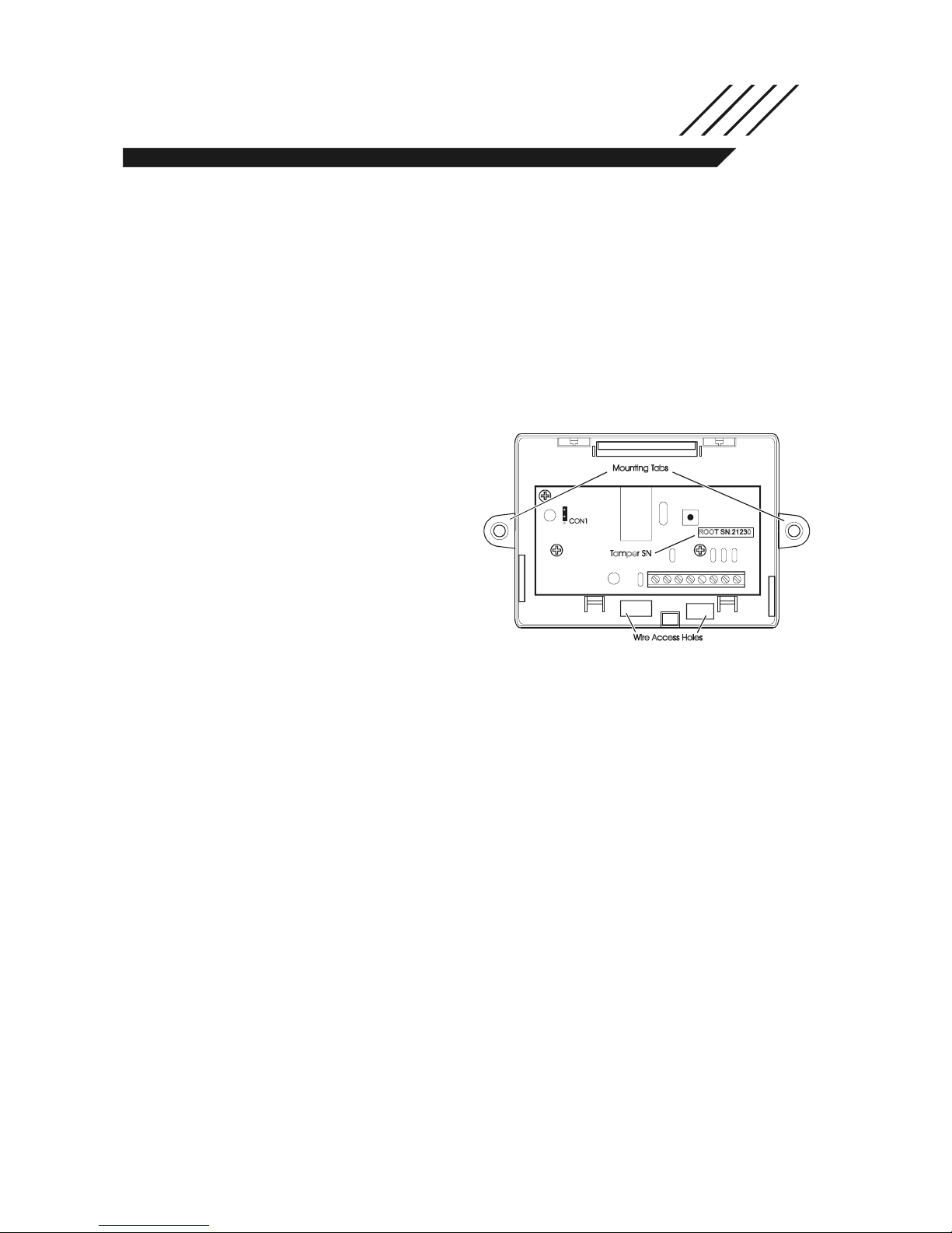
Figure 1: AMP-704
SW1
Control Panel Compatibility
• PC4020/PC4020CF v3.0 and higher
• PC5010 v2.0 and higher*
• PC5015 v2.2 and higher*
• PC5020/PC5020CF v3.0 and higher*
*Requires PC5100 Addressable Expansion Module
NOTE: For Commercial Fire applications use the AMP-704 only in conjunction with models
PC4020CF and PC5020CF control units.
IN G ND Z1 COM Z2 Z3 COM Z4
Mounting
Select a mounting location for the AMP-704. The module should be located in a dry location
and as close as possible to the points to be protected. Alternatively to the method explained
below, the PCB may be mounted in a metal cabinet using the standoffs provided with the
unit, refer to Figure 3.
1. Remove the cover using a flat blade screwdriver to push in the tab at the bottom of the
enclosure.
2. Pull the addressable loop and input wires through the wiring access holes located at the
bottom of the backplate.
3. Mount the device securely to the wall using the two mounting tabs on the backplate or
using the two mounting holes inside the backplate. To use the holes inside, the PCB must
first be removed. To do this, remove the 3 screws holding the PCB and lift it out.
CAUTION: When replacing the PCB, do not over-tighten the screws, the PCB
could be damaged.
NOTE: If the mounting tabs are not being used to mount the device, they can be broken off.
4. Wire the module and configure the EOL supervision jumper as per the instructions below.
5. Replace the cover and insert the cover screw.
Wiring
Connect the AMP-704 wiring as indicated below:
Loop Current vs. Wiring Distance
Figure 2: AMP-704 Wiring
(from PC4020/PC5100)
Total Loop
Current (mA)
10 2880/878 5143/1568
20 1620/494 3645/1111
30 1010/308 2520/768
40 771/235 1736/529
50 600/183 1250/768
70 400/122 800/244
100 200/61 310/95
120 135/41 155/47
150 100/30 124/37
170 96/28 120/35
22 AWG
distance (ft/m)
18 AWG
distance (ft/m)
SUPERVISED,
POWER LIMITED
PC4020: PGM1/PGM2
PC5100: STR+
PC4020: AUX-
PC5100: STR-
IN GND Z1 COM Z2 Z3 COM Z4
SUPERVISED,POWER LIMITED
Refer to EOL supervision
for proper input connections
Rating: 12V, 1mA
CAUTION: Connect only DSC addressable devices to the addressable loop
connections. Connection of any other type of device will impair operation. Any
devices other than addressable devices that require power to operate must be
powered separately.
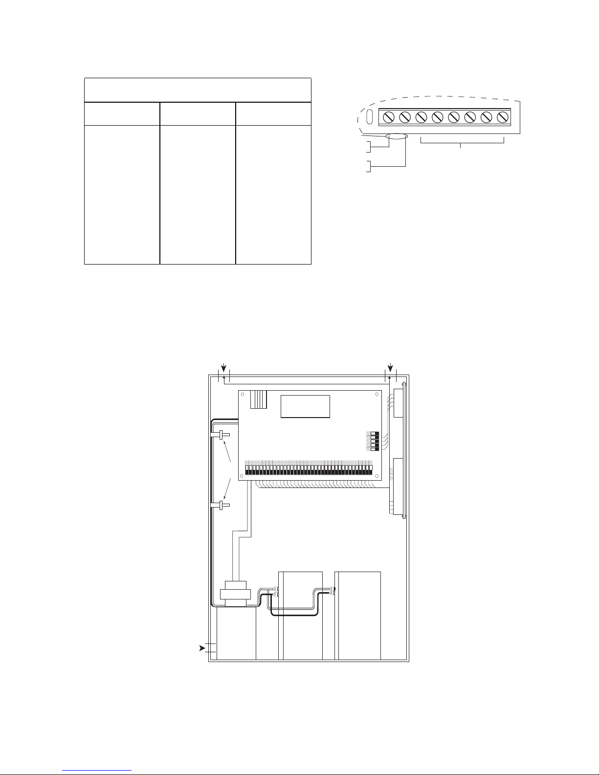
Figure 3: Power Limited and Non-Power Limited Wiring (this diagram is representative of
all compatible control panels)
POWER
LIMITED
POWER
LIMITED
Compatible
Control Panel
WARNING: Do not route any wiring
NON-POWER
LIMITED
Cable
Tie
Class2
Power
Limited
37VA
Voltage
Barrier
over circuit boards. Maintain at least
1" (25.4mm) separation.
KEYBUS
Power Limited
Cable Tie (not provided)
To prevent wires from falling onto batteries,
secure them to the enclosure or to the plastic
standoff located under the control panel.
For fire installations,
Non-Power
Limited
-
+
lines come through
conduit connections.
-
+
7Ah7Ah
AMP-704
INSTALL BATTERY & AC WIRING AS SHOWN
IMPORTANT: A minimum 1/4" (6.4mm) separation must be main-
tained at all points between battery/primary AC wiring and all other
wiring connections. The AMP-704 is mounted inside the compatible
control unit's enclosure using 3 nylon spacers 3/8" (9.6mm).
 Loading...