

Page 1

Page 2
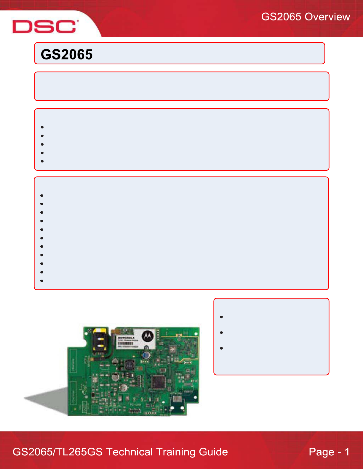
Overview:
The GS2065 provides primary or backup GSM/GPRS communication for the PC9155 2-way wireless security
suite
Specifications:
Dimensions : 3.937"x5.875"x0.625" (100mmx150mmx15mm)
Weight : 68 g
Input Voltage : 10 to 13.8 V (from the PC-Link header)
Current Draw : 100 mA at 12V (400 mA during the GSM transmission)
Operating Environment : 40 to 104 F (5 to 40 C)
Features:
Back up and primary GSM/GPRS alarm communication
Panel remote uploading/downloading support via GSM/GPRS
Supervision heartbeats via GSM/GPRS
128-bit AES encryption over GSM/GPRS
Full event reporting
SIA format
PC-Link connection
SIM card included
Signal strength and trouble display
Activating and initializing through Connect 24
Quad-Band: 850 MHz, 1900 MHz, 900 MHz and 1800 MHz
Compatible Receivers:
Sur-Gard System I Receiver:
version 1.10 and higher
Sur-Gard System II Receiver:
version 2.00 and higher
Sur-Gard SG-DRL3-IP: version 2.20
and higher (for Sur-Gard System III
Receiver)
Page 3
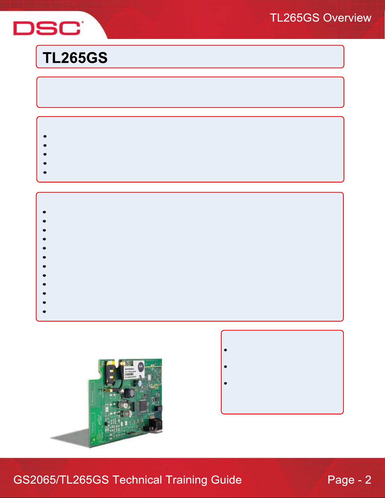
Overview:
The TL265GS is an Internet and GSM/GPRS Dual-Path alarm communicator for the PC9155 2-way
wireless security suite
Specifications:
Dimensions : 3.937"x5.875"x0.75" (100mmx150mmx18mm)
Weight : 78 g
Input Voltage : 10 to 13.8 V (from the PC-Link header)
Current Draw : 100 mA at 12V (400 mA during the GSM transmission)
Operating Environment : 40 to 104 F (5 to 40 C)
Features:
Fully redundant Internet and GSM/GPRS dual-path alarm communication
Integrated call routing
Panel remote uploading/downloading support via GSM/GPRS and Internet
Supervision heartbeats via GSM/GPRS and Internet
128-bit AES encryption via GSM/GPRS and Internet
Full event reporting
SIA format
PC-Link connection
SIM card included
Signal strength and trouble display
Activating and initializing through Connect 24
Quad-Band: 850 MHz, 1900 MHz, 900 MHz and 1800 MHz
Compatible Receivers:
Sur-Gard System I Receiver: version
1.10 and higher
Sur-Gard System II Receiver: version
2.00 and higher
Sur-Gard SG-DRL3-IP: version 2.20
and higher (for Sur-Gard System III
Receiver)
Page 4
BEFORE YOU BEGIN
Have the following ready before installation:
Control panel backup battery
Battery connection harness
Batteries for WT5500 2-way wireless keypad
Screwdriver
Prior to installing a GS2065 and TL265GS, contact your monitoring station to determine if it is a master reseller or
visit www.connect24.com and become an authorized dealer. In both instances, you will acquire a Profile Number,
Installer ID Number and an Installer Password.
PLEASE NOTE: You need to activate the SIM card and initialize the communicator 24 HOURS BEFORE
INSTALLATION (Steps 1).
Summary of Installation Steps
Step 1 – Initialize an account via Connect 24 Website (www.connect24.com)
Step 2 – Install and wire the communicator to the control panel (on-site)
Step 3 – Load the programming and test for best signal strength location
Step 4 – Program communication options on the control panel via keypad
Step 5 – Test communicator
Page 5
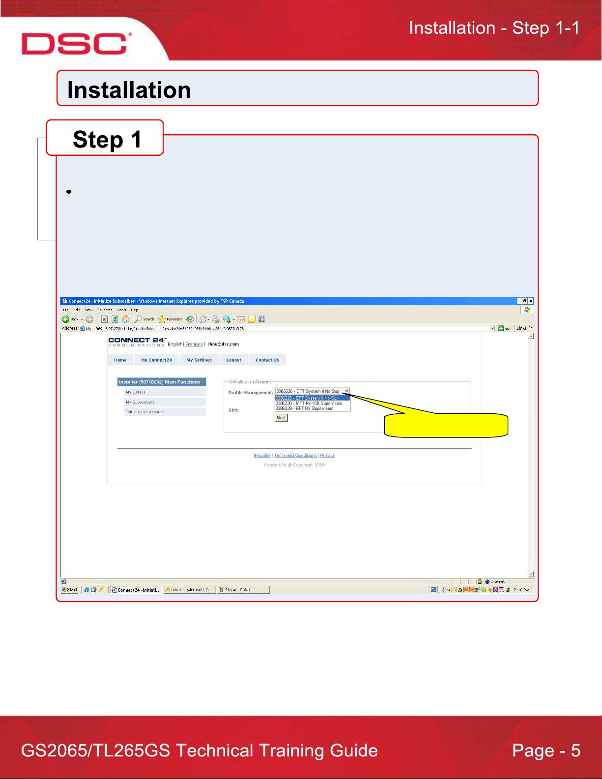
Step 1 – Initialize an account via Connect 24 Website (www.connect24.com)
Login to Connect 24 website by using Installer ID and Password and initialize an account
Select Profile Number
Select Product Module
Enter SIM card number
Enter DNIS number (if necessary)
Enter Account Code
Select Supervisory Type (if necessary)
Enable DHCP (if necessary)
Enter IP Address (TL260GS/TL265GS only)
Enter Subnet Mask Address (TL260GS/TL265GS only)
Enter Gateway Address (TL260GS/TL265GS only)
Select Rate Plan
Confirm information and submit activation application
Page 6
Step 1 – 1
Select Profile Number
Select Profile
Page 7
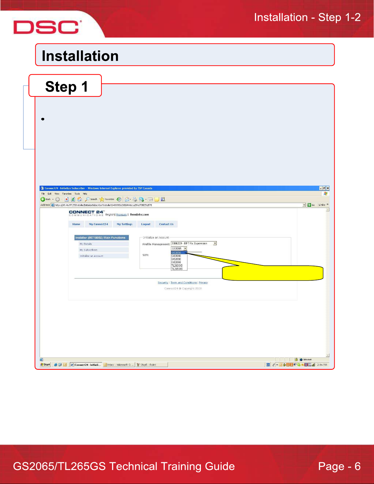
Step 1 – 2
Select Product Module
Select Module Number
Page 8

Step 1 – 3
Enter SIM card number
Enter SIM Number
Page 9

Step 1 – 4
Enter DNIS number (if necessary)
Enter Account Code
Select Supervisory Type (if necessary)
Enable DHCP (if necessary)
Note: If DHCP is not selected, manual entries of the IP Address, Subnet Mask Address and Gateway
Address are required (next page).
Enter DNIS
Enter Account Code
DHCP Option
Select Supervisory
Type
Page 10

Step 1 – 5 (only available if DHCP is not selected)
Enter IP Address (TL265GS only)
Enter Subnet Mask Address (TL265GS only)
Enter Gateway Address (TL265GS only)
IP Address
Subnet Mask
Gateway
Page 11

Step 1 – 4
Select Rate Plan
Rate Plan
Page 12

Step 2 – Install and wire the communicator to the control panel (on-site)
GS2065/TL265GS: See details in product manual for PC9155 control panel
Page 13

Step 3 – Load the programming and test for best signal strength location
Ensure the SIM card is inserted
Power up the control panel
The communicator will be programmed by loading the pre-programmed configuration from Connect 24
automatically
Check Green LEDs. You must achieve full or medium signal strength. See details in product manual
If signal strength is poor, must relocate the control panel or use an external extension antenna kits
Page 14

Step 4 – Program communication options on the control panel via keypad
GS2065/TL265GS with PC9155 control panel
o [301], [302], [303], [305] Program Communication Path
• DCAA - Internal (Ethernet 1, Ethernet 2, GPRS 1, GPRS 2)
• DCBB - Ethernet Receiver 1
• DCCC - Ethernet Receiver 2 (backup)
• DCDD - GPRS Receiver 1
• DCEE - GPRS Receiver 2 (backup)
o [350] option: Program Communication Format (Communicator)
• (If Option [301] (above) is set to DCAA, Option [350] must be set to
SIA, sub-option 5)
o [351] to [376] options: Program Call Direction
o [382] option: Enable T-LINK Interface (Option [5])
o [383] option: Program Back up Communication
o [167] option: Enable Communication Wait For ACK (Set to 60 seconds)
o [401] option: Enable DLS Session Through GPRS or Ethernet (Option
[1])
Page 15

Step 5 – Test communicator
1. Disconnect incoming phone line from TIP and RING on the control panel
2. Verify that LED 2 is on, this indicate that the unit is active
3. Create an alarm transmission
4. Verify alarm transmission by calling monitoring station
5. Re-connect the phone line, if necessary
For back-up communication applications, perform steps 1 to 5
For primary communication applications, perform steps 3 and 4 only
Page 16

Communicator Controlled Call Routing
– Backup (dual-path)
– Redundant (dual-path)
Required Programming
Panel Sections [301], [302],[303] and [305]
•Any of them could be programmed as DCAA
Communicator Sections [005]
Option [4] ‐ Primary and backup path
[ON]: GPRS path primary, Ethernet path backup
[OFF]: Ethernet path primary, GPRS path backup
Option [5] ‐ Redundant between GPRS path and Ethernet path
[OFF]: Disable redundancy
[ON]: Enable redundancy
Backup Mode 1:
Ethernet Primary, 4 Receivers
TX 1
Ethernet Receiver 1
Tx 1 failed, Tx2
Ethernet Receiver 2
Tx 2 failed, TX3
GPRS Receiver 1
Tx 3 failed, Tx4
GPRS Receiver 2
IP Receiver* 1
IP Receiver 2
IP Receiver 3
IP Receiver 4
Page 17

Backup Mode 2:
Ethernet Primary, 2 Receivers
Ethernet Receiver 1
Ethernet Receiver 2
Tx 1 failed, Tx2
Tx 2 failed, TX3
GPRS Receiver 1
GPRS Receiver 2
Tx 3 failed, Tx4
Backup Mode 3:
GPRS Primary, 4 Receivers
Tx 2 failed, TX3
Ethernet Receiver 1
TX 1
IP Receiver 1
IP Receiver 2
IP Receiver 1
Ethernet Receiver 2
GPRS Receiver 1
GPRS Receiver 2
Tx 3 failed, Tx4
IP Receiver 2
TX 1
IP Receiver 3
Tx 1 failed, Tx2
IP Receiver 4
Page 18

Backup Mode 4:
GPRS Primary, 2 Receivers
Ethernet Receiver 1
Ethernet Receiver 2
GPRS Receiver 1
Tx 2 failed, TX3
IP Receiver 1
TX 1
Tx 3 failed, Tx4
IP Receiver 2
GPRS Receiver 2
Tx 1 failed, Tx2
Redundant Mode 1: 4 Receivers
– (Redundancy between GSM/GPRS path and Ethernet/Internet path)
Ethernet Receiver 1
TX 1, Ethernet path
IP Receiver 1
Ethernet Receiver 2
GPRS Receiver 1
GPRS Receiver 2
TX1 failed, TX 2 via Ethernet path
IP Receiver 2
TX1, GPRS path
IP Receiver 3
TX 1 failed, TX 2 via GPRS path
IP Receiver 4
Page 19

Redundant Mode 2: 2 Receivers
– (Redundancy between GSM/GPRS path and Ethernet/Internet path)
Ethernet Receiver 1
Ethernet Receiver 2
GPRS Receiver 1
GPRS Receiver 2
TX 1, Ethernet path
IP Receiver 1
TX1, GPRS path
TX1 failed, TX 2 via Ethernet path
IP Receiver 2
TX 1 failed, TX 2 via GPRS path
Page 20

PC9155 Panel Controlled Call Routing
Backup (triple‐path)
Panel section [383] – Options [2],[3] and [4] enabled
Panel section [380], Option [6] disabled
Redundant (triple‐path)
Panel sections [351] – [376] Options enabled
Alternate (triple‐path)
Panel section [380] – Option [6] enabled
Required Programming
Panel Sections [301], [302],[303] and [305]
• Phone #: Phone number of the receiver
• DCBB: Ethernet Receiver 1
• DCCC: Ethernet Receiver 2
• DCDD: GPRS Receiver 1
• DCEE: GPRS Receiver 2
PC9155 Panel Controlled Call Routing
–Backup: Panel Section [383] – Options [2],[3] and [4] enabled
Example
1‐800‐xxxxxxx[301]
1‐800‐xxxxxxx[301]
DCBB[302]
DCBB[302]
DCCC[303]
DCCC[303]
DCDD[305]
DCDD[305]
Phone Line path
Tx 1 5 failures, Tx2
Ethernet Receiver 1
Tx 2 5 failures, Tx3
Ethernet Receiver 2
Tx 3 5 failures, Tx4
GPRS Receiver 1
TX 1
Phone Line Receiver 1
IP Receiver 1
IP Receiver 2
IP Receiver 3
Page 21

PC9155 Panel Controlled Call Routing
–Redundant: Panel Sections [351] – [376] Options enabled
Example
1‐800‐xxxxxxx[301]
1‐800‐xxxxxxx[301]
DCBB[302]
DCBB[302]
DCCC[303]
DCCC[303]
DCDD[305]
DCDD[305]
Phone Line path
Ethernet Receiver 1
Ethernet Receiver 2
GPRS Receiver 1
TX 1
TX 1
TX 1
TX 1
PC9155 Panel Controlled Call Routing
–Alternate: Panel section [380] – Option [6] enabled
Example
Phone Line path
TX 1
Phone Line Receiver 1
IP Receiver 2
IP Receiver 3
IP Receiver 4
Phone Line Receiver 1
1‐800‐xxxxxxx[301]
1‐800‐xxxxxxx[301]
DCBB[302]
DCBB[302]
DCCC[303]
DCCC[303]
DCDD[305]
DCDD[305]
5 rounds total
Ethernet Receiver 1
Ethernet Receiver 2
GPRS Receiver 1
Tx 1 1 failure, Tx2
IP Receiver 1
Tx 2 1 failure, Tx3
IP Receiver 2
Tx 3 1 failure, Tx4
IP Receiver 3
 Loading...