

DSC PowerSeries Neo, 3G8080-EU Installation Manual
3G8080-EU HSPA Controller
V1.1 Installation Manual [ENG]
3G8080-EU Controlador HSPA
Manual de instalación V1.1 [ESP]
WARNING: This manual contains information on limitations regarding product use and function and information on the limitations as to liability of the manufacturer. The entire manual should be carefully read.

Tabla de contenidos
Warning: Installer Please Read Carefully 6
Note to Installers 6
System Failures 6
Access by Intruders 6
Component Failure 6
Compromise of Radio Frequency (Wireless) 6
Criminal Knowledge 6
Failure of Replaceable Batteries 6
Inadequate Installation 6
Inadequate Testing 6
Insufficient Time 6
Motion Detectors 6
Power Failure 6
Security and Insurance 6
Smoke Detectors 7
Telephone Lines 7
Warning Devices 7
General 8
IMPORTANT 8
Safety Information 8
Alarm.com Introduction 8
HSPA 3G Module - 3G8080-EU 8
Contact Information 9
Features 9
Communicator Ratings 9
Communicator Compatibility 10
Installation 10
Tools and Supplies Required 10
Enable Module 12
Connect the 3G8080-EU 12
Step 1: Connect Data Bus 12
Step 2: Connect Power 12
Step 3:Connect the PC-Link Cable 12
Step 4: Connect External Antenna (Optional) 12
Step 5: Power Up 12
HSPA Phone Test (Module Registration) 12
Panel Settings 14
Central Station and Telephone Line Settings 14
Notifications 15
Panel Settings Changed Automatically 15
Clock 16
- 2 -

Tabla de contenidos
Troubleshooting 16
Module Status Information 16
Troubleshooting LEDs 17
LED Functions 17
LED Details 18
LED L1 (Red) 18
LED L2 (Yellow) 18
LED L3 (Yellow) 19
LED L4 (Green) 19
LED L5 (Yellow) 19
Various Module States (Modes) 19
Improving Wireless Signal Strength 20
Walking the Customer through New User Setup on the Web 20
Interactive Service Menu 21
Interactive Menus 21
Installer Programming 21
User Functions 22
Limited Warranty 23
International Warranty 23
Warranty Procedure 23
Conditions to Void Warranty 23
Items Not Covered by Warranty 23
Disclaimer of Warranties 23
Installer’s Lockout 23
Out of Warranty Repairs 23
End User License Agreement 24
SOFTWARE PRODUCT LICENSE 24
DESCRIPTION OF OTHER RIGHTS AND LIMITATIONS 24
LIMITED WARRANTY 25
Regulatory Information 25
Advertencia: Instalador lea cuidadosamente 29
Nota para los Instaladores 29
Fallas del Sistema 29
Acceso por Intrusos 29
Falla de un Componente 29
Compromiso de Frecuencia de Radio (Inalámbricos) 29
Conocimiento Criminal 29
Falla en Baterías Reemplazables 29
Instalación Inadecuada 29
Prueba Incorrecta 29
- 3 -

Tabla de contenidos
Tiempo Insuficiente 29
Detectores de Movimiento 29
Falla de Energía 30
Seguridad y Seguro 30
Detectores de Humo 30
Líneas Telefónicas 30
Dispositivos de Advertencia 30
General 31
IMPORTANTE 31
Información sobre seguridad 31
Presentación de Alarm.com 31
Módulo 3G HSPA - 3G8080-EU 31
Información de contacto 32
Características 32
Características del comunicador 32
Compatibilidad del comunicador 33
Instalación 34
Herramientas y suministros requeridos 34
Habilitación del módulo 35
Conexión del 3G8080-EU 35
Paso 1: Conexión del Bus de datos 35
Paso 2: Conexión de la alimentación 35
Paso 3:Conexión del cable PC-Link 36
Paso 4: Conexión de la antena externa (opcional) 36
Paso 5: Encendido 36
Prueba de teléfono HSPA (Módulo de registro) 36
Configuración del panel 37
Configuración de la estación central y la línea telefónica 37
Notificaciones 38
Configuración del panel modificada automáticamente 38
Reloj 39
Solución de problemas 40
Información de estado del módulo 40
LED de solución de problemas 41
Funciones de LED 41
Detalles de LED 41
LED L1 (rojo) 41
LED L2 (amarillo) 42
LED L3 (amarillo) 43
LED L4 (verde) 43
LED L5 (amarillo) 43
Estados diversos de módulo (Modos) 43
- 4 -

Tabla de contenidos
Mejora de la potencia de la señal inalámbrica 44
Guía para el cliente para la configuración de usuario nuevo en la web 44
Menú de servicio interactivo 46
Menús interactivos 46
Programación del instalador 46
Funciones de usuario 47
Garantía Limitada 48
Garantía Internacional 48
Procedimiento de la Garantía 48
Condiciones para Cancelar la Garantía 48
Items no cubiertos por la Garantía 48
Renuncia de Garantías 48
Cierre del Instalador 49
Reparaciones Fuera de la Garantía 49
Acuerdo de licencia de usuario final 49
LICENCIA DE PRODUCTO DE SOFTWARE 49
DESCRIPCIÓN DE OTROS DERECHOS Y LIMITACIONES 49
GARANTÍA LIMITADA 50
Información reglamentaria 50
- 5 -

Warning: Installer Please Read Carefully
Note to Installers
The warnings on this page contain vital information. Asthe only individual in contact with systemusers, it is the installer’s re sponsibility to
bring each item in this warning to the attentionof all users of this system.
SystemFailures
This system has been care fully designed to be as effective as possible.
There are circumstances, however, involving fire, burglary, or other
types of emergencies where it may not provide protection. Any a larm
system of any type may be compromised deliberately or may fail to
operate as expected for a variety of reasons. Some, but not all, of the
reasonsmay be:
Access by Intruders
Intruders may enter through an unprotected access point, circumvent a
sensing device, evade detection by moving through an a rea of insufficient coverage, disconnect a warning device, or interfere with or
prevent the proper operationof the system.
Component Failure
Although every effort has been made to make this system as reliable as
possible, the system may fail to function as intended due to the fa ilure
of a component.
Compromiseof Radio Frequency (Wireless)
A device's signals may not reach the receiver under all circumstances,
which could include: metal objects placed on or near the ra dio path,
deliberate jamming or other inadvertent ra dio signal interference.
Criminal Knowledge
This system contains security features which were known tobe effective at the time of manufacture. It ispossible for persons with criminal
intent to develop techniques which reduce the effectiveness of these
features. It is important that your security system be reviewe d periodically to e nsure that its features remain effective and that it is updated
or replaced if it is found that it does not provide the protection e xpected.
Failure of Replaceable Batteries
This system’s wireless tra nsmitters have been designed to provide several years of battery life under normal conditions. The expected battery
life is a function of the device environment, usage, and type. Ambient
conditions such as high humidity, high or low temperatures, or large
temperature fluctuations may reduce the expected battery life. While
each transmitting device has a low battery monitor which identifies
when the batteries need to be replaced, this monitor may fail to operate
as expected. Regular testing and maintenance will keep the system in
good operating c ondition.
Inadequate Installation
A security system must be installed properly in order to provide adequate protection. Every installation should be evaluated by a security
professional to ensure that all access points and a reas are covered.
Locks and latches on windows and doors must be secure and operate
as intended. Windows, doors, walls, c eilings a nd other building materials must be of sufficient strength and constructionto provide the level
of protection expected. A reevaluation mustbe done during and after
any construction a ctivity. An evaluation by the fire and/or police
department is highly recommended if this service is available.
Inadequate Testing
Most problemsthat would prevent an alarm system from operating as
intended can be found by regular testing and maintenance. The complete system should be tested weekly and immediately after a break- in,
an attempted break-in, a fire, a storm, an earthquake, an accident, or
any kind of constructionactivityinside or outside the premises. The testing should include all sensing devices, keypads, consoles, alarm indicating devices, and any other operational devices that are part of the
system.
Insufficient Time
There may be circumstances when the system will opera te as intended,
yet the occupants will not be protected from an emergency due to their
inability to respond to the warnings in a timely manner. If the system is
remotely monitored, the response may not occur in time to protect the
occupants or their belongings.
Motion Detectors
Motion detectors can only detect motion within the designated areas as
shown in their respective installation instructions. They cannot discriminate between intruders and intended occupants. Motion detectors
do not provide volumetric area protection. They have multiple bea ms
of detection and motion can only be detected in unobstructed areas
covered by these beams. They cannot detect motion which occurs
behind walls, ceilings, floors, closed doors, glass partitions, glass doors
or windows. Any type of tampering whether intentional or unintentional such as masking, painting, or spraying of any material on the
lenses, mirrors, windows or a ny other part of the detection system will
impair its proper operation. Passive infrared motion detectors operate
by sensing changes in temperature. However their effectiveness can
be reduced when the ambient temperature rises near or a bove body
temperature or if there are intentional or unintentional sources of heat
in or near the detec tion area. S ome of these heat sources could be heaters, radiators, stoves, barbecues, fireplaces, sunlight,steam vents, lighting and so on.
Power Failure
Control units, intrusion detectors, smoke detectors and many other security devices require an adequate power supplyfor proper operation. If
a device operates from batteries, it is possible for the batteries to fail.
Even if the batteries have not failed, they must be charged, in good condition and installed correctly.If a device operates only byAC power,
any interruption, however brief, will render that device inoperative
while it does not have power. Power interruptions of any length a re
often accompanied by voltage fluctuations which may damage electronic equipment such as a security system. After a power interruption
has occurred, immediately conduct a complete system test to ensure
that the system opera tes as intended.
Security and Insurance
Regardless of itscapabilities, an alarm system is not a substitute for property or life insurance. An alarm system alsois not a substitute for property owners, re nters, or other occupants to act prudently to prevent or
minimize the harmful effects of an emergency situation.
- 6 -

Smoke Detectors
Smoke detectors that are a part of this system may not properly alert
occupants of a fire for a number of reasons, some of which follow.
The smoke detectors may have been improperly installed or positioned.
Smoke may not be able to reach the smoke detectors, such as when the
fire is in a chimney, walls or roofs, or on the other side of closed doors.
Smoke detectors may not detect smoke from fires on another level of
the residence or building. Every fire is different in the amount of
smoke produced and the r ate of burning. Smoke detectors cannot
sense alltypes of fires equally well. Smoke detectors may not provide
timely wa rning of fires caused by carelessness or safety haza rds such
as smoking in bed, violent explosions, escaping gas, improper storage
of flammable materials, overloaded e lectrical circuits, children playing
with matches, or arson. Even if the smoke detector operates as intended, there may be circumstances when there is insufficient warning to
allow all occupants to escape in time to a void injury or death.
Telephone Lines
If telephone lines are used totransmit alarms, they may be out of service or busy for certain periods of time. Also an intruder may cut the
telephone line or defeat its operation by more sophisticated means
which may be difficult to detect.
Warning Devices
Warning devices such as sirens, bells, horns, or strobes may not warn
people or waken someone sleeping if there is an intervening wall or
door. If warning devices are located on a differe nt level of the re sidence or premise, then itis less likely that the occupants will be alerted
or awakened. Audible warning devices may be interfered with by
other noise sources such as stere os, radios,televisions, air conditioners,
other a ppliances, or passing traffic. Audible warning devices, however
loud, may not be heard by a hearing-impaired person.
- 7 -

General
IMPORTANT
This installation manual shall be used in conjunction with the control panel. All the safety instructions specified
within that manual shall be observed. The control panel is referenced as the “panel” throughout this document.
This installation guide provides the basic wiring, programming and troubleshooting information. Use this guide
in conjunction with the installation manual available online from the DSC website at www.dsc.com.
The HSPA/CDMA alarm communicator is a fixed, wall-mounted unit, and shall be installed in the location specified in these instructions. The HSPA/CDMA alarm communicator module should NOT be installed inside of
the metal alarm panel casing; doing so will significantly impair cellular and RF (Z- Wave) transmissions.The
equipment enclosure must be fully assembled and closed, with all the necessary screws/tabs, and secured to a
wall before operation. Internal wiring must be routed in a manner that prevents:
l Excessive strain on wire and on terminal connections,
l Interference between power limited and non power limited wiring,
l Loosening of terminal connections, or
l Damage of conductor insulation.
WARNING: Never install this equipment during a lightning storm.
Safety Information
The installer must instruct the system user on each of the following:
l Do not attempt to service this product. Opening or removing covers may expose the user to dangerous vol-
tages or other risks.
l Any servicing shall be referred to service persons only.
l Use authorized accessories only with this equipment.
l Do not stay close to the equipment during device operation.
l Do not touch the external antenna.
Alarm.com Introduction
The purpose of this guide is to introduce you to the Alarm.com communicator modules. The following sections
identify these modules and offer you a brief overview of their capabilities. Some capabilities and features vary
based on the Alarm.com service plan selected. Visit www.alarm.com/Dealer or contact Alarm.com for more
information.
Note: The HSPA3G module is available in the following models:
Module Model
HSPA3G 3G8080
3G8080-EU
The module 3G8080-EU contains the subassembly 3G8055 NEO and the PC- Link to the RS422 conversion
interface. The module is compatible only with NEO Alarm Control Unit models HS2128, HS2064, HS2032
and HS2016 software versions 1.1 and above.
HSPA 3GModule - 3G8080-EU
The HSPA module enables wireless reporting of all alarms and other system events from the DSC Neo control
panel using an all-digital, HSPA wireless (cellular) network. The module can be used as the primary communication path for all alarm signaling, or as a backup to a telephone connection to the central monitoring sta-
- 8 -

tion. The wireless alarm signaling and routing service is operated by Alarm.com. The HSPA module also features integrated support for Alarm.com’s home automation solution with built-in Z-Wave capabilities.
Note : Alarm.com’s home automation solution with built- in Z- Wave capabilities is not EN501311:2006/A1:2009 and EN50136-1:2012 evaluated.
Contact Information
For additional information and support on Alarm.com modules, initial account setup, home automation, and all
other Alarm.com products and services, please visit: www.Alarm.com/dealer or contact Alarm.com technical
support at: 1-866-834-0470.
Features
l 128-bit AES encryption via cellular and Internet (NIST validation certificate number: 3162).
l Back up or primary cellular alarm communication.
l Automatically switches to 2G (EDGE/GPRS) if HSPA(3G) service is not available.
l Full event reporting to central station.
l Cellular periodic test transmission.
l Integrated call routing.
l Panel remote uploading/downloading support via cellular.
l PC-LINK connection.
l Programmable labels.
l SIA and Contact ID (CID) formats supported.
l Signal strength and trouble display LEDs.
l Subscriber Identity Module (SIM) card included with communicator.
l Supervision heartbeats sent via cellular.
l 2-way audio capable when used with audio module HSM2955(R) - Refer to HSM2955(R) manual
Communicator Ratings
Model 3G8080-EU
Power Supply Ratings
Input Voltage
(providedby DSC NEO compatible control panel)
11.3V - 12.5VDC
Current Consumption
Standby Current (Average Value) 100mA@12V(I)
Alarm (Transmitting) Current (Peak Value) 200mA@12V (I)
Cellular Network HSPA 3G
Operating Frequency QuadBandGSM/GPRS/EDGE + HSPAin 850/900/2100MHz
Environmental Specifications
Operating Temperature -10°C to 55°C
Storage Temperature -34°C to 60°C
Humidity 93%RH non-condensing
Mechanical Specifications
Dimensions 6" x 8.9" x 1.3"
Weight (grams) 365g (I)
- 9 -

Communicator Compatibility
Communicator
3G8080-EU
Receiver/
Panel
Receiver
Description
l Sur-Gard System I-IP Receiver, version 1.13+
l Sur-Gard System II Receiver, version 2.10+
l Sur-Gard SG-DRL3-IP, version 2.30+ (for Sur-Gard System III
Receiver)
l Sur-Gard SG-DRL4-IP version 1.20+ (for Sur-Gard System IV
Receiver)
l Sur-Gard SG-DRL5-IP version 1.00+ (for Sur-Gard System 5
Receiver)
l HS2016, version 1.1+
Panel
l HS2032, version 1.1+
l HS2064, version 1.1+
l HS2128, version 1.1+
Note: Enter [*][8][Installer Code][900][000] at keypad to view the panel version number.
Products or components of products, which perform communications functions only shall comply with the requirements applicable to communications equipment as specified in EN60950-1, Information Technology Equipment - Safety - Part 1: General Requirements. Such components include, but are not limited to: hubs; routers;
NIDs; third-party communications service providers; DSL modems; and cable modems.
Installation
Follow these guidelines during installation.
l Before affixing the communicator to a wall, verify the HSPA signal level at the installation location. On a
keypad, press and hold the 5 key for 2 seconds to view the HSPA signal level. An installation location
with a sustained signal level of two or more bars is recommended.
l Do not exceed the panel total output power when using panel power for the 3G8080-EU module, har-
dwired sensors, and /or sirens. Refer to the specific panel installation instructions for details. Only one
3G8080-EU module can be used per panel.
l To minimize potential interference with cellular signaling, avoid mounting the communicator in areas with
excessive metal or electrical wiring, such as furnaces or utility rooms.
Do not mount the 3G8080-EU communicator inside of the metal alarm panel enclosure.
Tools and Supplies Required
You will need the following tools and supplies:
l Small flat-head and Phillips screwdrivers
l Screws (included)
l Antenna (included)
l 16 pin ribbon cable (included)
- 10 -
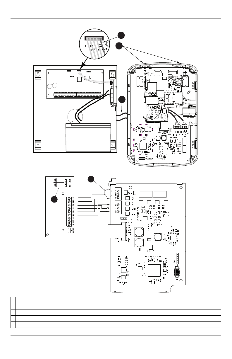
HS2016/2032/2064/2128
PCLINK_2
A
B
C
PCL-422
RX-
RX+
TX+
TX-
+12V
GND
+12V
GND
D
E
A Red wire on alarm controller PCLink_2 Header
B Antenna access ports
C Quad cables (100' / 30m maximum)
D Red wire on PCL-422 PCLink Header
E HSPAController Boardpower terminals. Can be connected to power supply module (HSM2204/2300).
- 11 -

Enable Module
For the Alarm.com module to communicate with the panel, section [382] option 5 at the panel must be set to
ON. This section is OFF by default and must be enabled for the system to function properly. This should be
done before connecting the PC Link cable to power up the module to ensure all initialization commands are processed properly.
Connect the 3G8080-EU
Caution: Ensure that the alarm panel is fully powered down (i.e., AC and battery disconnected) prior to connecting the 3G8080-EU.
Step 1:Connect Data Bus
The maximum cable length permitted for the data bus is 100ft/30m.
l Connect the RX+ terminal on the 3G8080-EU to the TX+ terminal on the PCL-422
l Connect the RX- terminal on the 3G8080-EU to the TX- terminal on the PCL-422
l Connect the TX- terminal on the 3G8080-EU to the RX- terminal on the PCL-422
l Connect the TX+ terminal on the 3G8080-EU to the RX+ terminal on the PCL-422
Step 2:Connect Power
The maximum cable length permitted for the power connection is 100ft/30m.
l Connect the GND terminal on the 3G8080-EU to the GND terminal on the PCL-422
l Connect the +12V terminal on the 3G8080-EU to the +12V terminal on the PCL-422
Step 3:Connect the PC-Link Cable
Note: To ensure correct orientation, refer to items A and C in the wiring diagrams for the proper position of
the red wire on the PC-link cable.
l Connect one end of the supplied PC-Link cable to the PC-Link header on the PCL-422
l Connect the other end of the PC-Link cable to the PC-LINK_2 header on the alarm panel
Step 4:Connect External Antenna (Optional)
Upgraded antennas are available for the 3G8080-EU if there is inadequate cellular reception at the preferred
mounting location. Contact DSC technical support for antenna options.
The 3G8080-EU has two covered access ports on the top of the enclosure. Remove the plastic tab covering the
desired port and either mount the antenna on the enclosure or use the opening to pass through the antenna cable.
Note: Due to the curvature of the enclosure, the plastic port covers are NOT interchangeable. Ensure that any
unused ports are covered with their original plastic tab.
Warning: The external antenna must be installed in a manner to prevent end users from accessing any conductive part of the anntena or antenna cable (i.e., recessed mounting or equivalent).
Step 5:Power Up
Connect panel battery and AC power. Once an HSPA module is connected to a powered control panel, view
key items on the LCD. Ensure that the module has been fully connected to the alarm panel via quad cable as
shown in wiring diagram.
HSPA Phone Test (Module Registration)
To initiate module communication with Alarm.com and the HSPA network for the first time, perform an
“HSPA phone test”. Note that the phone test can also be used at any time by the installer to force communication with Alarm.com. Perform a phone test by pressing and holding [3] for two seconds. A phone test
- 12 -

can also be completed through the Interactive Services menu. To perform the phone test, press [*][6] followed
by the master code and [04].
The panel indicates when the HSPA phone test has completed by activating the siren output on medium volume
for 2 seconds followed by full volume for 2 seconds. However, if the phone test was initiated via the [3] key,
or through the Interactive Services menu, the siren will not sound. All display lights and LCD pixels turn on.
This indicates that Alarm.com has received and acknowledged the signal. This does not guarantee that the signal went through to a central station; it confirms that Alarm.com’s Network Operations Center received the
signal. The central station should be contacted directly to verify that the signal was received on the correct
account and that the central station routing settings have been set up correctly. If the signal does not go through
to the Central Station, the panel will display a “Failure to Communicate” message. Double check the account’s
Central Station Forwarding Settings on Alarm.com and contact technical support if the trouble persists.
- 13 -

Panel Settings
CentralStation and Telephone Line Settings
Central Station and telephone line settings will be automatically configured through the CS Forwarding
Settings page of the Alarm.com Dealer Site. The following are the panel settings that will be configured via
the Dealer Site page (when required) and should not be configured in the panel:
Section Option Description
015 7 Telephone line monitoring
300 [001] -- PanelCommunication Path - Receiver 1
300 [002] -- PanelCommunication Path - Receiver 2
300 [003] -- PanelCommunication Path - Receiver 3
300 [004] -- PanelCommunication Path - Receiver 4
301 [001] -- Communication telephone number 1
301 [002] -- Communication telephone number 2
301 [003] -- Communication telephone number 3
301 [004] -- Communication telephone number 4
309 [001] -- System Call Direction - Maintenance
309 [002] -- System Call Direction - Test Transmission
310 [000] -- System account number
310 [001] -- Partition 1 account number
310 [002] -- Partition 2 account number
310 [003] -- Partition 3 account number
310 [004] -- Partition 4 account number
310 [005] -- Partition 5 account number
310 [006] -- Partition 6 account number
310 [007] -- Partition 7 account number
310 [008] -- Partition 8 account number
311 [001] -- Partition 1 Call Direction - Alarm/Restore
311 [002] -- Partition 1 Call Direction - Tamper/Restore
311 [003] -- Partition 1 Call Direction - Opening/Closing
312 [001] -- Partition 2 Call Direction - Alarm/Restore
312 [002] -- Partition 2 Call Direction - Tamper/Restore
312 [003] -- Partition 2 Call Direction - Opening/Closing
313 [001] -- Partition 3 Call Direction - Alarm/Restore
313 [002] -- Partition 3 Call Direction - Tamper/Restore
313 [003] -- Partition 3 Call Direction - Opening/Closing
314 [001] -- Partition 4 Call Direction - Alarm/Restore
314 [002] -- Partition 4 Call Direction - Tamper/Restore
314 [003] -- Partition 4 Call Direction - Opening/Closing
315 [001] -- Partition 5 Call Direction - Alarm/Restore
315 [002] -- Partition 5 Call Direction - Tamper/Restore
315 [003] -- Partition 5 Call Direction - Opening/Closing
316 [001] -- Partition 6 Call Direction - Alarm/Restore
- 14 -

Section Option Description
316 [002] -- Partition 6 Call Direction - Tamper/Restore
316 [003] -- Partition 6 Call Direction - Opening/Closing
317 [001] -- Partition 7 Call Direction - Alarm/Restore
317 [002] -- Partition 7 Call Direction - Tamper/Restore
317 [003] -- Partition 7 Call Direction - Opening/Closing
318 [001] -- Partition 8 Call Direction - Alarm/Restore
318 [002] -- Partition 8 Call Direction - Tamper/Restore
318 [003] -- Partition 8 Call Direction - Opening/Closing
350 [001] -- Receiver 1communicator format
350 [002] -- Receiver 2communicator format
384 2 Communicator backup options
Notifications
The following panel settings may alter the behavior of customer notifications:
Section Option Description
015 4
If this option is ON, keyfob arming notifications will not be associated with a specific
user
Panel Settings Changed Automatically
Some panel settings are changed automatically when the HSPA/CDMA module is connected to the control
panel. These settings should not be altered. They are:
Section Option Value Description
015 6 OFF
017 6 OFF
019 6
024 5 OFF
041 - 00 User Access Codes must be6-digits
377
377
377
Swinger Shutdown
(Maintenance)
AC Failure
Communication Delay
Wireless Device Low
Battery Transmission
Delay
Set accordingto
dealer's Alarm.com
setting
010
Random valuebetween
001 and 030
001
Master code is not changeable and must be
OFF to ensure the module communicates the
correct master code
Daylights saving time must be disabled to
ensure panel time is accurate
Enables Duress Code changes from
Alarm.com
Realtime clock must bedisabledto ensure
paneltime is accurate
Swinger Shutdown for maintenance signals
must be set to 010to ensuretrouble
notifications can be sent.
AC Failure Communication Delay should be
set between 001 and 030 to ensure
notifications for power failures are received
Wireless Device Low Battery Transmission
Delay should be set to 001 to ensure
notifications for low batteries arereceived
- 15 -

Section Option Value Description
380 1 ON
380 2 OFF
380 5 OFF
382 6 OFF
804 [sensor #] 003 Five minute delay [07]
Communications must be enabledfor the
module to communicate with the panel
System should transmit alarm restores
immediately whenthe zoneis restored
The redundant communications methodmust
be set as backup.
AC Failure Transmission Delay should be in
minutes
High Traffic Shutdown should be set to five
minutes for devices being used with
Alarm.com's Activity Monitoring.
Note: This feature may reduce the battery life
of wireless PIR sensors. In order to avoid this,
hardwiredPIR sensors may be used instead.
Clock
The HSPA/CDMA module sets the panel clock when it connects to Alarm.com and then updates it every 18
hours. It is important to select the correct panel time zone on the Alarm.com website, or the panel time will
not be accurate. If a system is powered up before the customer account has been created, the time zone will
default to Eastern Standard Time.
Troubleshooting
Module Status Information
Module status information for verifying and troubleshooting the module connection status or errors can be
found through the Interactive Services menus. To access these, press [*][8][Installer Code ][851]. See the
following table for potential module states.
Status Description
Idle Most common state. Module is not actively sendingdata and no errors arepresent.
Roaming Roaming on partner network.
SIM Missing The SIM cardis missing.
PowerSave
Mode
Registering... The module is trying to register on the HSPAnetwork.
Connection
Error
Radio Error
Server Error Identifies a server error. If it persists, the account may have been set up incorrectly.
Connected Currently connected andtransmitting information to the Alarm.com servers.
Connecting... In the process of connecting to Alarm.com.
Updating... Updating signal level.
AC power is down.
The moduleis registered on the HSPA network but cannot connect with Alarm.com. Contact
Alarm.com technical support for more information.
Radio portion of the moduleis not operating correctly. Power cycle the panel and call Alarm.com
technical support if the trouble persists.
In addition, some of the information can be retrieved via long key presses from the keypad. Press and hold the
following panel keys for 2 seconds to display the given information on the panel display. Most messages are displayed for less than 30 seconds but can be cut short by pressing the 0 Key for 2 seconds.
- 16 -
 Loading...