

DSC 3G4010 Installation Manual

3G4010
3G (HSPA) Cellular Alarm
Communicator
INSTALLATION MANUAL
V4.0
Warning: This manual contains informationon limitations regarding product use andfunction and inform-
ationon the limitations as to liability of the manufacturer. Theentiremanual should becarefullyread.

2

Introduction 4
Features 4
Technical Specifications 5
Ratings 5
Identificationof Parts 6
Description 7
Installingthe 3G4010 7
Connectingthe 3G4010 9
Status LEDs 9
Operating Modes 9
Normal Mode 9
Service Mode 10
Operating Principles 10
Simulated Landline Mode 10
Panel Transmission Monitoring (PTM) 11
Cellular Communications Sequence 11
Inputs 11
Outputs 12
Activating the Outputs 12
Reporting Codes 12
Swinger Shutdown 12
Hardware Default 13
Communicator Reset/Update 13
Low Power Radio Shutdown 13
SMS Command and Control 13
Arming/Disarming the Security Panel 14
Remote Control of PGM 14
Phone Number Call Direction 15
C24 Communications Remote Programming 15
Troubleshooting Guide 15
3G4010 Wiring Diagrams 19
EULA 25
Regulatory Information 25
Warranty 26
3
IMPORTANT
The equipmentis fixed, wall-mounted and shall be installed in the position specified in these instructions (see Figure 1:Parts).
The equipmentenclosure must be fully assembled and closed, with all the necessary screws/tabsand secured to a wall before
operation. Internal wiring must be routed in a manner that prevents:
- Excessivestrain on wire and on terminal connections
- Loosening of terminal; connections
- Damage of conductor insulation
WARNING: Never installthis equipment duringa lightningstorm!
Instruct the end-user to:
- Not attempt to service this product. Opening or removing covers may expose the user to dangerous voltages or other risks.
Any servicing shall be referred to trained service persons only.
- Use authorized accessories onlywith this equipment.
Do not dispose of the battery in fire or water. Disposing of the batteryin a fire will cause rupture and explosion.
Do not dispose of the waste battery as unsorted municipal waste. Consult your local regulations and /or lawsregarding recycling with regard to this lead-acid battery.Doing so will help protect the environment. Some of the materials that are found within
the battery could becometoxicifnot disposed of properly and may affectthe environment.
NOTICE TO USERS, INSTALLERS,AUTHORITIES HAVING JURISDICTION ANDOTHERINVOLVED PARTIES
This product incorporates field-programmable software. In order for the product to comply with the requirements in the Standard for Control Units and Accessoriesfor Fire Alarm Systems,UL 864, certain programming features or optionsmustbe limited
to the specific values or not used at all as indicated below.
Program Feature or Option Permitted in UL 864 (Y/N)? Possible Settings Settings permitted inUL864
Supervision Yes 5 minutes /60 minutes 5 minutes (see note below)
Inputs/Outputs Yes Fire/Burg signals Fire related signals only
SMS Remote Control No Enable/Disable Disable
NOTE:This product has been tested in accordance with UL 864 9th edition. According to this edition of the standard, the supervision window for reporting single-technology communicator trouble shall be set to five minutes. However, the product can be
installed in accordance with the requirements of NFPA72 2013 edition, which allows for a 60-minute supervision window.
Introduction
The 3G4010 is a cellular communicator that sends alarm system information to a Sur- Gard System I-IP, II,III, IV or 5 receiver
through a 3G (HSPA) or 2G (GPRS) cellular network.Thiscellular communicator can be used with UL/ULCListed compatible
control units, as indicated in the manufacturer's installation instructions.
NOTE: The 3G4010 is designed to work with the Contact ID communication format as described in the SIA DC-05 standard
and the SIA DC-03 standard for 300 baud. Before completing the field installation of the alarm monitoring system please
ensure communication with the supervising central station is successful by sending several events and getting confirmation that
they have been received.
Features
l Dual-band UMTS/HSPA; Quad-Band GSM/EDGE Radio
l Advanced Carrier Selection
l Bi-color Wireless Signal Strength Indicator
l 3G (HSPA) / 2G (GPRS) / Internet communication with Sur-Gard SG-System I-IP / II/III / IV / 5
l Compatible with 4-digitor 10-digit ContactID communication format as described in SIADC-05 Standard and the SIA DC-
03 standard for 300 baud. Example of suitable compatible alarm panels:
DSC Models PC1864,PC1832, PC1616, PC4020.
l Panel Transmission Monitoring for up to four phone numbers
l Simulates landline
l Switchesautomatically to the 3G (HSPA) or 2G (GPRS) network in the event of landline trouble (e.g., line down)
l Four Programmable (NO/NC/SEOL) Inputs
l 12V 1.2Ah battery (optional, notincluded)
l Case Tamper Output
l Landline overvoltage protection
l Four Programmable Outputs
l DLS support for status, firmware updates and remote debug enable
l Remote Firmware Upgrade
l Remote Diagnostics
l Panel Format Detection
4

l SMS Command and Control
l Phone number call direction
l Easy enrollment with C24 Communicationsvia VRU, web or mobile interface
Technical Specifications
The inputvoltage to the 3G4010 can be drawn from the UL/ULCListed control panel or provided by an external UL/ULC Listed
power supply rated for the application (external power-limited source).
NOTE: The power supply must be Class2, Power Limited. For residential applications a suitable power adaptor is model DSC
ADP1310-NAU or DSC ADP1320-NAU(for USA) and model DSC ADP1310-NA or DSC ADP1310-NA (for Canada).
Ratings
Power Supply Ratings
Input Voltage:
Current Consumption
Average Current (standby with PSTN
connected):
Average Current (standby without
PSTN connected):
Transmission Current(no battery): 225mA*
* Plus anycurrent drawn from the 3G4010 AUX+ terminal
WorkingVoltage Range
With Battery: 11-14Vdc
Without Battery: 9 -14Vdc
BatteryType:
Batterycharging voltage: 13.75Vdc
Batterycharge currentlimit: 360mA
NOTE:Batterymustbe replaced every 3-5 years.
NOTE:When using the battery,use DSCADP 1310-NA(U) or ADP 1320-NA(U) power adapter
Operating frequency - 2G
(GSM/GPRS/EDGE):
Operating frequency - 3G
(UMTS/HSPA):
Antenna gain: 2.0dBi
Environmental Specifications
Operating temperature: 0°C-49°C (32°F-120°F)
Humidity: 93%RH Maximum (non-condensing)
Mechanical Specifications
Dimensions (metal enclosure,
painted):
Weight (without battery): 900g / 3.2oz
SimulatedTelcoLoop specifications (TIP/RING)
On-Hook Voltage: 12Vdc
Off-HookVoltage (Maximum): 22Vdc
Loop Current : 25mA
Loop Resistance : 600 Ohms
Alternate construction
Dimensions(enclosure for 3G4010): 138mm x 257mmx55mm / 5.4" x 8.8" x 2.2"
Weight (alternate construction
enclosure without battery):
9-14Vdc (use separately listed control panel or power supply) or 13.8Vdc (use DSC
ADP1310-NAx or ADP1320-NAxpower adapter)
40mA*
55mA*
sealed, rechargeable type, rated 12V/1.2Ah
(for 24hr standby time)
850/1900MHz
850/1900MHz
138mm x 224mmx55mm / 5.4” x 8.8” x 2.2”
1300g / 2.8lbs
5
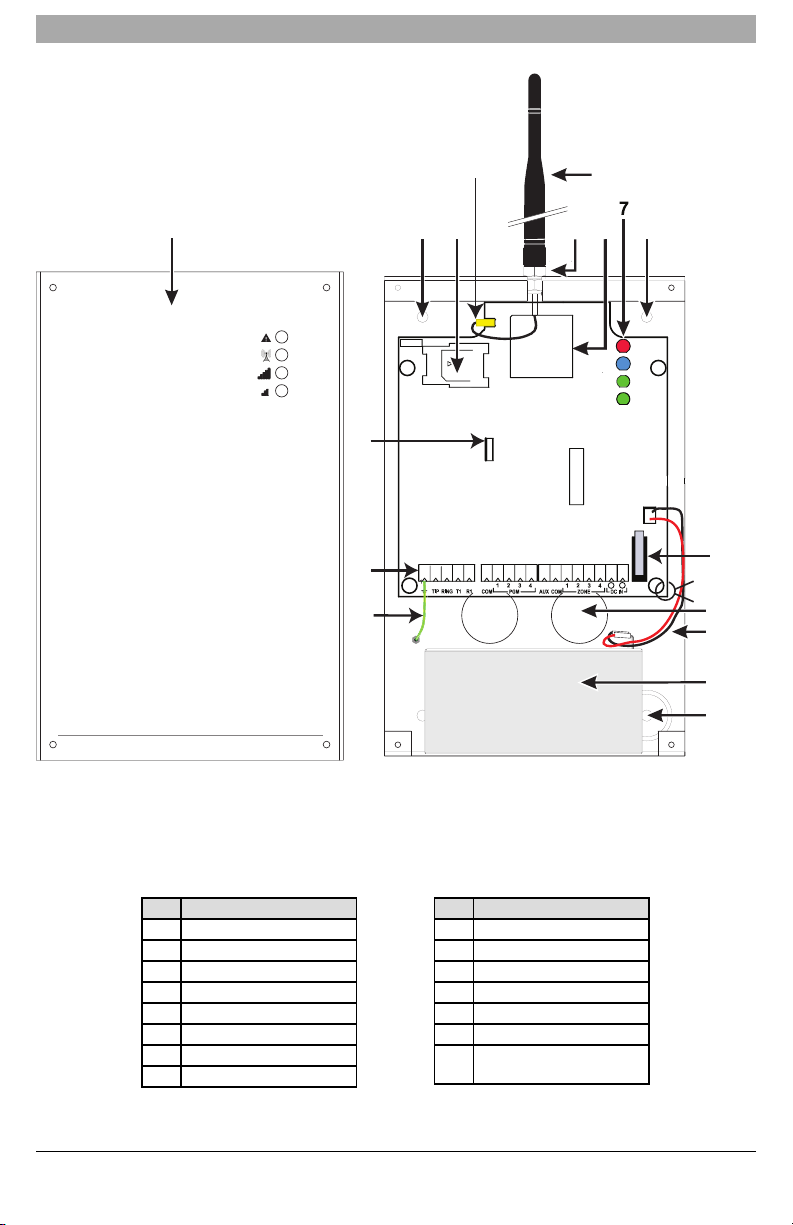
Identification of Parts
CON3
LED 2
BAT +
OPE N
+
LED 1
BAT -
-
LED 4
LED 3
UA673
SE
R
IAL NU MB E R
1
44
5
3
2
8
6
9
10
11
13
12
15
14
4
tie wrap
Figure 1:Parts
All circuits are classified for UL installations as Power Limited/ClassII Power Limited except for the battery leads which are not
power limited. Do not route any wiring over circuit boards.Maintain at least 1” (25.4mm) separation. A minimum 1/4” (6.4mm) of
separation must be maintained at all points between Power Limited wiring and all other non-Power Limited wiring. Route wires
as indicated above.
For ULC Commercial Fire Monitoring Installations, connections between the fire alarm control panel inputs/outputs (telephone
interface Tip/Ring or outputrelay contacts) and 3G4010 inputs/outputs (T1/R1, Z1-Z4, PGM1-4) shall be run in metallicconduit
within 18m(ULC) and in the same room.
Part
1 Metal Casing
2 3G Antenna
3 Antenna Mounting Hardware
4 Anchor Screw Holes (3mm)
5 Antenna Connector
6 SIM Card Holder
7 StatusLEDs (See page 9)
8 3G (HSPA) Radio Module
9 PC-Link Connector
10 Tamper Switch
11 Terminal Blocks
12 BatteryLeads
13 Cable Entry
14 EarthGround Wire
15
12V/1.2Ah Battery
(not included)
Part
This equipment 3G4010 is fixed and shall be installed by Service Personsonly (Service Person is defined as a person having
the appropriate technical training and experience necessaryto be aware of hazards to which that person may be exposed in
6

performing a task, and of measures available to minimize the risks to that person or other persons). It shall be installed and
used within an environment that provides the pollution degree max 2, over voltages category II,in non-hazardous, indoor locations only. This manual shall be used with the Installation Manual of the relevantalarm control panel. All instructions specified
within that manual mustbe observed.
Description
This 3G4010 manages transmissions to a central station and can simulate the landline in the event of trouble (e.g., landline
down) or even substitutethe landline completely in areas where the 3G or 2G cellular service is provided and a landline is not
available.
The 3G4010 has the capability of communicating alarmsignals via the 3G or 2G data network. This capability ensures a fast,
reliable path to central stations equipped with a Sur-Gard SystemI-IP / II/ III / IV / 5 receiver. By connecting a 3G4010 to a control panel's standard PSTN interface, telephone-based Contact ID or SIA signals are decoded and seamlesslyrouted through
the 3G or 2G network to any of the compatible receiver options.
The performance of the 3G4010 depends greatly on cellular network coverage. Therefore, it should not be mounted without
first performing placement tests to determine the best location for reception (minimum of one green LED ON). Optional
antenna kits– GS15/25/50-ANT(15ft/4.6m,25ft/7.6mor 50ft/15.2m)– are available.
For UL Residential Fire and Burglary installations, the 3G4010 is listed as a sole means of communication or as a back up
when used in conjunction with a POTS line (dialer).
For UL Commercial Burglary installations,the 3G4010 is listed as a sole means of communication (supervision windowof 200s
required at monitoring station) or as a back-up when used in conjunction with a POTS line (dialer).
The 3G4010 shall be powered from any compatible listed control unit or compatible listed power supply that complies with the
ratings specified on page 1. The power supply shall be listed for burglary applications and provide a minimum of 4 hours
standby power capabilities. An example of a suitable listed compatible control unitis the DSC Model PC1864 with an AUX output rated 11.1 - 12.6VDC. An example of a suitable Listed power supply is DSC Model PC5204 with an AUX outputrated 11.6 -
12.6VDC.
For ULC Commercial Fire Monitoring installations the 3G4010 is listed as a passive communication system when used in conjunction with a POTS line (dialer). Fire alarms shall be sent simultaneously over both communication methods (cellular network
and PSTN).
For ULC Commercial Burglary installations the 3G4010 is listed as a passive communication system with communication line
securitylevel P2 when used as a back up in conjunction with a POTS line (dialer).
For ULC Residential Fire and Burglary installationsthe 3G4010 is listed as a sole means communication or as a back up when
used in conjunction with a POTS line (dialer).
Installing the 3G4010
C24 Communications Enrolment
The 3G4010 requires enrolment with C24 Communicationsto operate. For more information, please visitwww.connect24.com,
contactC24 Communicationscustomer service at 1-888-251-7458 (US) / 1-888-955-5583 (Canada) or contactthe central station to inquire if they are a C24 Communications Master Reseller.
NOTE: Enrollmentwith C24 Communicationsshould be performed before turning on the 3G4010 unit.
Before inserting or removing the SIM card, please ensure the unit is turned off.
Step 1 - Initialize the 3G4010 withC24 Communications
The 3G4000 can be initialized with C24 Communications by:
VRU - 1-866-910-3865
web - www.connect24.com
mobile - m.connect24.com
To complete enrolment,a C24 profile, installer ID/PIN(or web credentials) and the 20-digit SIM number are required.
NOTE: The SIMactivation process with the cellular carrier typicallytakes between five and ten minutes to complete.
Step 2 - Determine the Best Signal Location
1. Remove the front cover by removing the four cover screws.
2. Apply power (DC and/or battery).The 3G4010 is nowin placement test mode.
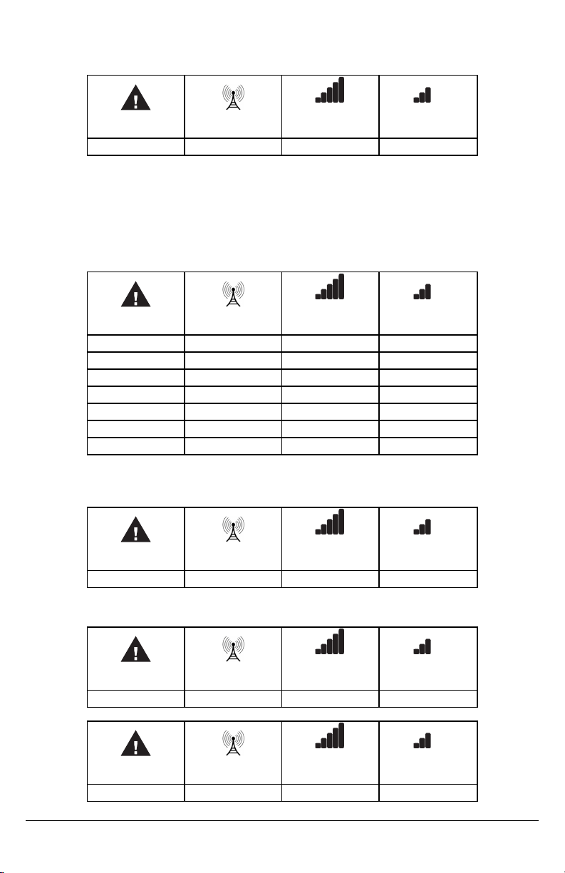
Step 2a – SIM card is activated.
The red LED will be on solid, the blue LED will be off and the signal strength LEDs will display the average signal strength. In
this state, the 3G4010 is registered to the cellular network.
Red Blue
ON OFF - -
Yellow/Green
(Top)
7
Yellow/Green
(Bottom)
Ifthe signal strength is too low (bottom signal LED off or flashing), the 3G4010 will move to Step 3 and scan for carrierswithsufficientsignal strength and attach to the carrier.Ifthe 3G4010 is connected to a carrier with sufficient signal strength (minimum of
bottomsignal strength LED on solid), it will move to Step 4.
Step 2b – SIM cardis not activated
The red LED will flash, the blue LED will be off and the signal strength LEDs will display the average signal strength.
Red Blue
Yellow/Green
(Top)
Yellow/Green
(Bottom)
FLASHING OFF - -
In this state,the 3G4010 is unable to register to the cellular network because it isinactive. The signal strength indicated is from
any nearbycell tower (including cellular towers belonging to non-roaming partners) and does not necessarily reflect the signal
strength of the intended network. The 3G4010 will remain in this state until the SIM is activated.Once the SIM is activated,the
3G4010 will move to Step 2a.
Step 3 – Carrier Scanningdue toinsufficientsignal strength
The 3G4010 will scan the surrounding cellular network and connect to the carrier to provide a signal strength of at least 7 CSQ.
When this action is being performed, all four LEDs will activate to show a scanning sequence.The LEDs will cycle from top to
bottomand then bottom to top. This cycle will continue until the 3G4010 is connected to a carrier with a signal strength above7
CSQ (minimu of bottom signal strength LED on solid).
Red Blue
Yellow/Green
(Top)
Yellow/Green
(Bottom)
FLASH ON OFF OFF OFF
OFF FLASH ON OFF OFF
OFF OFF FLASH ON OFF
OFF OFF OFF FLASH ON
OFF OFF FLASH ON OFF
OFF FLASH ON OFF OFF
FLASH ON OFF OFF OFF
Once this is completed, the 3G4010 will move to Step 4.
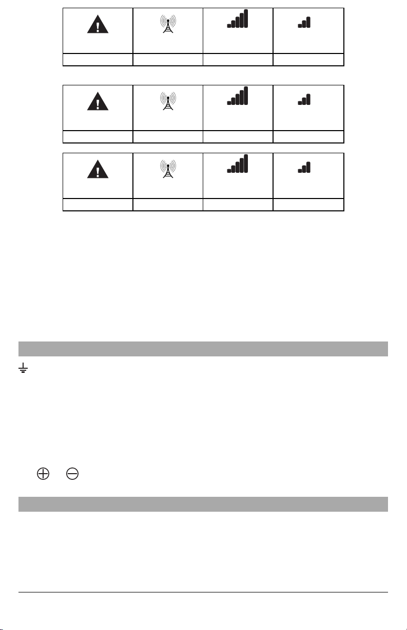
Step 4 - Acquire C24 Communications programming
The red LED will be on solid and the blue LED will flash. The flashing ofthe blue LED indicates that the 3G4010 hasrequested
programming from C24 Communications and is waiting for a response.
Red Blue
Yellow/Green
(Top)
Yellow/Green
(Bottom)
ON FLASHING - -
Once remote programming is completed, the blue LED will switch to solid and the 3G4010 will move to Step5.
Step 5 – Receiver Initialization
The red LED and the blue LED are both solid and the signal strength LEDs are off.
Red Blue
Yellow/Green
(Top)
Yellow/Green
(Bottom)
ON ON OFF OFF
When the 3G4010 sends a requestto communicate with the central station, the top signal strength LED will begin flashing.
Red Blue
Yellow/Green
(Top)
Yellow/Green
(Bottom)
ON ON FLASHING OFF
When the central station communicates back with the 3G4010,the top signal strength LED will turn on solid.
8
Red Blue
ON ON ON OFF
When the 3G4010 sends a requestto communicate with the nextcentral station, the bottom signal strength LED will begin flashing
Yellow/Green
(Top)
Yellow/Green
(Bottom)
Red Blue
ON ON ON FLASHING
and turn on solid when it receives a communication back from the central station.
Red Blue
ON ON ON ON
Ifat least one of the central stations did not respond back to the communicator, the signal strength LED corresponding to that
central station will turn off.Once the initialization sequence is complete, the 3G4010 will move on to steadystate operation.
Step 6 - Mount the 3G4010
1. Power down the 3G4010 by removing the DC power source and battery leads.
2. Using the cabinet, mark the four screw locations.Drill the anchor screwholes.
NOTE: Check for cable conduits and water pipes before drilling.
3. Using anchor screws (not provided), mount the cabinet to the wall.
4. Run the cables through the cable entry [13] or through the cabinet knockouts.
5. Completethe connections on the terminal blocks [11].
NOTE: Ensure that power and Telco circuit connectionsare made only after the cabinet has been secured to the building or
structure, and has been connected to the protectiveearth ground. Descriptions of the terminals can be found in the ‘Connecting
the 3G4010’ section.
6. Reattach the front cover [1]securelyto the cabinet.
NOTE: Please refer to Figure 2 at the end of this manual for wiring diagrams.
Yellow/Green
(Top)
Yellow/Green
(Top)
Yellow/Green
(Bottom)
Yellow/Green
(Bottom)
Connecting the 3G4010
(1) Earth Ground - This terminal must be connected to the Mains Earth, in order to comply with the Telecommunications
Network Safety Standards (Overvoltage Protection Requirements).
TIP (2) / RNG (3) External Telephone Line - These terminals mustbe connected directly to the incoming telephone line.
T1 (4) / R1 (5) Internal Telephone Line - These terminals mustbe connected to the TIP and RING of the control panel.
COM (6,12) Common- This terminal is connected internally to Power Ground.
PGM1 (7),PGM2 (8),PGM3 (9), PGM4 (10) Programmable Open-collectorOutputs - These outputs can be activated bypro-
grammed events. Refer to ‘Activating the Outputs’ for details.The maximumcurrent sink of each output must not exceed 50mA.
AUX+ (11) Auxiliary Output- 9 to 14VdcOutput,500mA PTC Protected.
NOTE: Electrical current drawn from this terminal is drawn directly from the power supply. This must be added to the 3G4010
current when determining the total draw on the host panel or power supply.
Z1-Z4 (13-14-15-16) Programmable Inputs - These terminals can be set up to trigger events.Refer to ‘Inputs’ for details.
DC IN (17), (18) Device Power Supply - These terminals mustbe connected to a rated power supply.Once the con-
nections are completed,connectthe batteryleads (Red and Black wires, [12] in Figure 1) to a 12V, 7Ah battery.
Status LEDs
Operating Modes
The 3G4010 features two distinct operating modes: Normal Mode and Service Mode. The unit will be in Normal Mode when
the cover tamper is in a restored state. If a cover tamper is present, the unitwill be in Service Mode.
Normal Mode
The 3G4010 interface has four statusLEDs.The following describes the status LEDs when the communicator is in normal operating mode with the front cover in place.
9
 Loading...