

Page 1

3G2080(R)
Cellular Alarm Communicator - International
TL2803G(R)
Internet and HSPA Dual-Path Alarm Communicator -
International
Installation Guide v4.1
For installation manual visit www.dsc.com
Warning: This manual contains information on limitations regardingproduct use andfunctionandinformationon thelimitationsas totheliability of themanufacturer.The entiremanual shouldbe carefully read.
Page 2

WARNING: Installer please read
carefully
Note to Installers
The warningso n thispa ge conta in vitalinfo rmation. As the only individual in contact with system users, it ist he installer’s responsibility to b ring each item in this
warning to the atte ntion ofa llusers ofthissystem.
System Failures
Thissystemh asbe en carefullyd esigned to be aseffe ctivea spossible. There are
circumstances, ho wever, involving fire, burglary, or oth er types of e mergencies
whe re it may not provide p rotection. Any alarm system of an ytype may be compromised deliberat elyo r mayf ailto ope rate as expected for a varietyo f reasons.
Some, but not all,of the reasons may be:
Acc ess by Intruders
Intrud ersmayente r through an unp rotected accesspo int, circumvent a sensing
device, evade detection by moving through an area of insufficient coverage, d isconne ct aw arningdevice, orinterfere with orpreve ntth ep rope rope rationof the
system.
Component Failure
Although every effort has be enmad eto make thissystem asreliable as possible,
the systemmayf ailto function asinte nded due to the failure ofa compone nt.
Comprom ise of Radio Fre quency (Wireless) Devic es
Signalsmay no t reach the receiver und er all circumstances wh ich could include
metal objectsplaced on or near the radio path ord eliberate jamming oro ther inadvertent radio signa linterferen ce.
Criminal Knowledge
Thissystem conta ins security feature s which we re known t o be effective at the
timeo fmanufacture. It is possible forp ersons with criminalintent to develop te chnique swhich redu ce the effectiveness of the se feature s. It is important that the
securitysystemb e reviewed periodicallyto en sureth atits featu res remain effectivea ndt hat it isup dated or replaced if itis found that itd oes not provide the p rotection expected .
Failure of Re placeable Batte ries
Thissystem’s wirelesstransmitters ha ve be en designed t oprovide several years
of batte rylife unde r normal cond itions. The expecte db attery life is a function o f
the device environmen t,usage, and type. Ambient cond itionssuch ashigh humidity,h igh or low tempe rature s, or large tempera turef luctuation s may reduce the
expecte d batte rylife. Wh ile each tra nsmitting device ha sa low b attery monitor
which iden tifies when the batteries ne edt o be replaced, t his monitor may fail to
ope rate as expe cted. Reg ular testing an d maintenan ce willkeep the system in
goo do perating condition.
Inadequate Installation
A security system must be installed properly in orde r to provide a dequat e p rotection. Every installation shou ld be evaluat ed by a security profe ssiona l to
ensure tha t allaccess points an da reas are covered. Lo cks and latches on window sa nd do ors must be secure an d opera te as intend ed. Window s, doo rs,
walls,ceilingsa nd other bu ildingmaterialsmust be of sufficient strengt hand construction toprovide the levelof prote ction expected. Areevaluation must bedon e
during and afte rany con struction activity. Anevaluation by the fire and/o r police
dep artment ishigh lyrecommende dif thisserviceisa vailable.
Inadequate Testing
Mostp roblems that wo uld prevent a n alarm systemf rom ope rating as inten ded
can be found by regular testing and maintena nce.The complete system should
be tested wee klyan d immediatelya ftera brea k-in,a na ttempted b reak-in, a fire,
a storm,an earth quake, an acciden t, ora ny kind of construction activityinside or
outside the premises. The te sting shou ld include a ll sensing devices, keypad s,
consoles, alarm indicating d evices, and any o ther ope rational devices that are
part of the system.
Insufficie nt Time
There may be circumstancesw hen th e systemwillo perate asint ended, yet th e
occupan ts will no t b e p rotected fro m an e mergency due to the ir ina bility to
respon dto the warnings in a timelymann er. If the systemis remotely monitored,
the respon se maynot occur in timeto protect the occupant sor theirbe long ings.
Motion Det ectors
Motion detecto rscan on lyde tectmotion within the designate da reas assho wn in
their respective installation instructions. Th ey cann ot discriminate betw een
intrude rs and intend ed occupa nts. Motion detectors do not provide volumetric
area prote ction. Th eyha ve multipleb eams of detection a nd motion can only be
dete cted in unobstructe d areas covered by th ese beams. The y canno t dete ct
motion wh ich occurs beh ind wa lls, ceilings, f loor, closed d oors, glass partitions,
glass doors o r windo ws. Any type of tampering w hether inte ntional or un intent ional sucha smasking, painting, or spraying of any materialo nth elen ses, mirrors, windo ws or a ny ot her p art of th e detection system will impair its proper
ope ration.
Passive infrared motion de tectors opera teb y sensing cha nges in tempe rature.
However the ir effe ctiveness can be redu ced w hen the ambient tempera ture
rises near or above bodyte mperature o rif there are intention alor un inten tiona l
sources ofh eat in or near the d etection area. Someo f these heat sources could
be hea ters,radiat ors, stoves, barbe cues, fireplaces, sunlight, steamven ts, lighting and soo n.
Power Failure
Con trol units, intru sion det ectors, smoke de tectors a nd many oth er security
devicesre quirean ad equate po wersup plyfor proper opera tion. If ad eviceo perates fromb atteries,it is possible forth e batteriesto fail. Even if the batteries have
not failed, they must be charge d, in goo d condition a nd installed correctly. If a
device operate sonly by AC po wer, any inte rruption , however brief, will render
that de vice inop erative whileit d oesn oth ave powe r.Powe r interrupt ions of any
length are ofte n accompanied by voltage fluctuation swhich may damag e electronic equ ipment such a s a security system. Afte r a power interruption has
occurred, immediatelycon duct a complete systemte st to ensure that the system
ope rates asintend ed.
Security and Insurance
Reg ardlessof itscapa bilities, ana larmsystemis not asub stitute for property or life
insurance. Analarmsystema lsois not asub stitute for property owners,ren ters,o r
othe roccupa ntsto act pruden tlyto preven tor minimize the harmful effects of an
emergen cysituat ion.
Smoke Det ect ors
Smoked etectorst hat area pa rt oft hissystemmaynot properly alert occupants o f
a fire fo r an umber o f reasons, some of wh ich follow. The smoke de tectors may
have bee nimproperly installed orpo sitioned. Smoke mayno tbe able to reach the
smoked etectors, such aswhen the fireis in a chimney, w alls orroo fs, or on t he
othe rside of closed do ors. Smoke det ectorsmay not det ect smoke from fires on
ano ther levelof the residence or building.
Everyfire isd ifferent in the amoun t of smoke prod uced and th erate of burning .
Smoked etectorscan not sense alltype sof fireseq uallywell.Smoke detectors may
not provide timelywa rning of fires caused by carelessnessor safety hazards such
as smoking in bed , violent e xplosions, escaping gas, imprope r storag e of flammable materials, overloaded e lectrical circuits, children playing w ith matches, or
arson.
Even if the smoke dete ctor op erates as inte nded, there may be circumstances
whe nth ereis insufficient warning to allow allo ccupan tsto escape int imeto avoid
injuryor death.
Telephone Lines
If telepho nelines are used to transmita larms, they may be out of serviceo r busy
for certainp eriods of time. Also an intrud ermay cut the telepho neline or defeat its
ope ration by more soph isticated means which mayb ed ifficultto detect.
Warning Devices
Warning devices sucha s sirens,bells, horns, or strobes may not warn p eople or
waken someone sleeping ift here isan interven ing wallor door. If warning devices
are located on a differen tlevel oft he residence orpremise,t hen it islesslikely that
the occupan ts will be alerted or awaken ed. Audible wa rning d evices may be
interfere dwith by other noisesou rces such asstereos, radios,te levisions, air conditioners, other appliances, o rpassing tra ffic. Audible wa rning devices, howe ver
loud, maynot be heard by ahe aring-impaired person.
2
Page 3

General
IMPORTANT
This installation manual shall be used in conjunction with the control panel. All the safety instructions specified within that
manual shall be observed. The control panel is referenced as the “panel” throughout this document. This installation guide
provides the basic wiring, programming and troubleshooting information.
The HSPA(3G)/dual-path alarm communicator is a fixed, wall-mounted unit, and shall be installed in the location specified in
these instructions.The equipment enclosure must be fully assembled and closed, with all the necessary screws/tabs, and
secured to a wall before operation. Internal wiring must be routed in a manner that prevents:
l Excessive strain on wire and on terminal connections,
l Interference between power limited and non power limited wiring,
l Loosening of terminal connections,or
l Damage ofconductor insulation.
WARNING: Never installthis equipment during a lightningstorm!
Safety Information
The installer mustinstructthe system user on each ofthe following:
l Do notattemptto service this product.Opening or removing coversmay expose the user to dangerous voltagesor other
risks.
l Any servicing shall be referred to service personsonly.
l Use authorized accessories only with this equipment.
l Do notstayclose to the equipment during device operation.
l Do nottouch the external antenna.
Model Information
This manual covers the following models of alarm communicators: TL2803GR, TL2803G, 3G2080R, 3G2080 (850/1900MHz
operation),TL2803GR-EU, TL2803G-EU, 3G2080R-EU, 3G2080-EU (900/2100MHz operation), TL2803G-AU, 3G2080- AU,
TL2803GR-AU, and 3G2080R- AU (850/2100MHz operation). References to model names TL2803G (R) and 3G2080 (R)
throughout this manual apply to all specified models unless stated differently. Models ending in “R” include a built-in RS-232
interface for connecting to local third party applications.
The TL2803G(R)/3G2080(R) supportsintegration over cellular/IP, available with licensed third partyproduct solutions.Specific
programming for the related programming sections is to be provided by the third party. A current list of compatible third party
solutions can be found atwww.dsc.com.
3G2080(R): Is a HSPA(3G) cellular alarm communicator that sends alarm communication to Sur- Gard System I, II, III (SGDRL3IP),IV (SG-DRL4IP),and 5 (SG-DRL5IP) central station receivers via a HSPA(3G)/GPRS digital cellular network.
TL2803G(R): Isa dual-path HSPA(3G) Ethernet alarm communicator that sends alarm communication to Sur-Gard System I,
II,III,IV,and 5 central station receivers through Ethernet/Internetor a HSPA(3G)/GPRS digital cellular network.
The communicator can be used aseither a backup or primary communicator.The communicator supports Internet Protocol (IP)
transmission ofpanel and communicator events over Ethernet/Internet and/or HSPA/GPRS.
The cellular performanceof the 3G2080(R) or TL2803G(R) communicator depends greatly on HSPA(3G)/GPRS network coverage in the local area. The unit should not be mounted in the final location without first performing the communicator placement testbelow to determine the bestlocation for radio reception (minimumof one green LED ON). Optional antenna kits (GS15ANTQ, GS-25ANTQ and GS-50ANTQ) are available from DSC to improve signal strength asrequired.
NOTE: Prior to installation of the 3G2080(R) or TL2803G (R) communicator, confirm with the local service provider that the
HSPA(3G)/GPRS network is available and active in the area where the communicator will be installed, and that radio
signal strength (CSQ) isadequate.
Panel Mounting
The following communicators are compatible with HS2016, HS2032, HS2064, and HS2128 panels:
l
3G2080(R) (HSPA(3G)/GPRS only)
l
TL2803G(R) (Ethernet/Internet +HSPA(3G)/GPRS dual-path)
Features
l 128-bit AES encryption via cellular and Ethernet/Internet (NIST validation cert.number 2645).
l Back up or primary cellular alarm communication.
l Automaticallyswitches to 2G (EDGE/GPRS) ifHSPA(3G) service isnot available.
l Ethernet LAN/WAN 10/100 BASE-T (TL2803G(R) only).
l Fully redundant Ethernet/Internet and cellular dual-path alarm communication (TL2803G(R) only).
l Full eventreporting to central station.
3
Page 4

l Individual Internet and/or cellular periodic testtransmission.
l Integrated call routing.
l Visual Verification (Requires Sur-Gard System 5 Receiver)
l Remote firmware upgrade capability of the communicator and panel firmware via Ethernet and/or cellular.
l Panel remote uploading/downloading support via cellular and Ethernet/Internet.
l PC-LINK connection.
l Programmable labels.
l SIA and ContactID (CID)formatssupported.
l Signal strength and trouble display LEDs.
l Supervision heartbeats sent via cellular and Ethernet/Internet.
l Command and Control bySMS.
l Third partyintegration over cellular/IP.
Technical Specifications
The TL2803G(R) is also suitable to be used with a compatible control unit listed for dual line security transmission when used
in conjunction with a DACT or a Public Switched Data Network (PSDN) transmitter, where the PSDN provides the line security
and is the primary line. In this mode, alarm signals are to be sent simultaneously over both communication methods.
EN50131-1 Installation Requirements
For EN50131-1 compliant installations,the following programming optionsshall be setas described.
Supervision Heartbeat (required for ATS4 and ATS5):
l
[851][004] set to 0087h (135s heartbeat).
NOTE: The compatible receiver at ARC location shall have supervision window programmed for 1800s (ATS4) or 180s
(ATS5).
l
[851][005] options 1,2 and 3 shall be enabled
l
[851][005] option 8 shall be enabled
Testtransmission (required for ATS3):
l
[851] System test options [026-029] shall be enabled (FF) for the communication paths available.
l
[851][124-125] and [224-225] shall be programmed with time ofday for test transmission and 1440 minutes(24h) for test
transmission cycle
Configuration ofcommunication paths (all ATS classes)
l
[300][001] select option 02 for autorouting (this will allow transmission ofthe eventsover all available communication
paths in the system)
l
[380] enable option 5 (YES) for parallel transmission over all available communication paths(if redundant configuration is
desired)
l
[382] enable option 5 (YES) thiswill enable Alternate communicator
l
[384] enable the desired back-up configuration (receiver 2 back-up for receiver 1 or receiver 3 back-up for receiver 1).
Ratings Compatibility
Table 1: Communicator Ratings
Model
3G2080(R)
Cellularonly
Power Supply Ratings
10.8-12.5 VDC
Power is supplied from the panel’s PC-Linkheader or a PCL-422 module in remote
Input Voltage
cabinet installations.In remote cabinet installations, the PCL-422 module located with the
communicator ispowered by either an HSM2204 or an HSM2300. Refer to the PCL-422
installation instructions for details.
Current Consumption
Standby Current 90mA @ 13.66V 120mA @ 13.66V
Alarm (Transmitting) Current 400mA @ 12V
Operating Frequency 900MHz,1800MHz,2100MHz
TypicalAntenna Gain 2dBi
EnvironmentalSpecifications
Operating Temperature -10°C to 55°C
4
TL2803G(R)
Internet and Cellular
Page 5

Model
3G2080(R)
Cellularonly
TL2803G(R)
Internet and Cellular
Humidity 5% ~ 93% relativehumidity,non-condensing
Mechanical Specifications
Board Dimensions (mm) 100 × 150 ×15 100 × 150 ×15
Weight (grams)with bracket 310 320
Table 2: Compatible Receivers and Panels
Communicator Receiver/Panel Description
l Sur-Gard System I-IP Receiver, version 1.13+
l Sur-Gard System II Receiver,version 2.10+
3G2080(R) Receiver
TL2803G(R) Panel
l Sur-Gard SG-DRL3-IP,version 2.30+ (for Sur-Gard System IIIReceiver)
l Sur-Gard SG-DRL4-IP version 1.20+ (for Sur-Gard System IV Receiver)
l Sur-Gard SG-DRL5-IP version 1.00+ (for Sur-Gard System 5 Receiver)
l HS2016
l HS2032
l HS2064
l HS2128
NOTE: Enter [*][8][Installer Code][900] atkeypad to view the panel version number.
Communicator Installation Configuration
This Internet and HSPA dual-path alarm communicator shall be installed by service persons only (service person isdefined as
a person having the appropriate technical training and experience necessary to be aware of hazardsto whichthat person may
be exposed in performing a taskand can also take measures tominimize the risksto that person or other persons). The Communicator shall be installed and used within an environment that providesthe pollution degree max 2, overvoltagescategory II,
in non-hazardous, indoor locations only. This manual shall be used with the installation manual of the panel which is connected to the communicator. All instructionsspecified within the panel manual mustbe observed.
All the local rules imposed by local electrical codes shall be observed and respected during installation.
Installing the Ethernet Cable(TL2803G(R) Only)
A Category5 (CAT 5) Ethernet cable must be run from a source with Internet connectivityto the communicator module, inside
the panel. The communicator end of the cable must be terminated with an RJ45 plug, which will connectto the communicator’s
RJ45 jack after the communicator is installed.All requirementsfor installation of CAT5 Ethernet cable mustbe observed for correct operation ofthe communicator,including, but notlimited to, the following:
l Do NOT strip offcable sheathing more than required for proper termination.
l Do NOT kink/knot cable.
l Do NOT crush cable with cable ties.
l Do NOT untwistCAT5 pairs more than ½ in. (1.2cm).
l Do NOT splice cable.
l Do NOT bend cable atright angles or make any other sharp bends.
NOTE: CAT5 specification requires that any cable bend must have a minimum 2 in. (5 cm) bend radius. Maximum length of
CAT 5 cable is 328 ft.(100 m).
Inserting and Removing the SIM Card
1. Remove the front cover of the panel to accessSIM holder.
2. Remove power from the panel and disconnectthe battery and telephone line.
3.
On the SIM card holder push gentlyto slide the cover downwards to OPEN. This will unlatchthe SIMcard holder on the
top edge ofthe communicator PCB. (See Figure 3).
4. Tiltthe top of the SIM card holder downwards toaccessthe SIMcard.
NOTE: The SIM can be damaged by bending or scratching contacts.Use caution when handling SIMcards.
5. Insert or remove the SIMcard, noting the orientation ofthe notches on the SIM card and the SIM card holder.
6. When inserting a SIMcard, insert the card in the proper orientation and gently push the SIMcard holder down and slide
the holder as indicated by the arrow on SIM holder, to LOCK.
7. Reconnectthe backup battery and telephone line, apply AC power to panel, and replace the panel cover.
Running the RS-232 Cable (R models only)
When installing the communicator for use with third party applications an RS-232 cable must be connected between the third
party device and the communicator module.
NOTE: Maximum cable length for RS-232 cable is8 ft. (2.4 m).
Please refer to the installation manual for the third partydevice for wiring instructions.
5
Page 6

Installing Communicator in Panel
Brass Washer
Nylon washer (flat)
Nylon Washer
with bushing
(thicker flat washer)
Brass nut
Antenna
Mounting Tab
Mounting
Holes
Mounting Holes
Antenna
Cable
Mounting Plate
External Antenna
Screw Thread
Communicator
Board
Mounting
Plate
Stand Off
Installing Communicator with HS2016, HS2032, HS2064, and HS2128 Panel
NOTE: Before installing communicator or inserting/removing SIM,ensure that system power is OFF and telephone line is dis-
connected.
1.
To assemble supplied mounting bracket,perform the following:(See Figure 1).
a. Remove the 4 white plastic standoffsfrom the bag provided with the communicator kit.
b. Insert the 4 standoffsthrough the back ofthe mounting bracket,into the holes ateach corner. (The antenna mount-
ing tab should be facing away fromyou).
c. Placethe bracketon a flat, solid surface.Hold the communicator component side up and orientthe 4 holes on the
communicator with the 4 standoffs protruding from the bracket. Push the communicator firmlyand evenly onto the
standoffs until it issecurely attached to the mounting bracket.
d. Remove the panel frontcover.
e. Remove and discard the circular knockout located in the top-right section ofthe panel. (This hole will be used for con-
nection ofthe supplied radio antenna).
f. Connect the supplied 5” (12.7 cm) antenna cable to the radio, by passing the connector through the hole on backof
the mounting bracketto the communicator board. Pushthe antenna connector firmlyinto the socket on the cellular
radio. (See Figure 3).
Figure 1: Communicator Mounting Bracket
2. Install the Communicator into the panel:
a. Attach one end ofthe PC-LINK cable to the panel PCLINK_2 header on the panel (red wire goes on the right-hand
pin of the panel PCLINK_2 header (see Figure 3)).
b. Insert the assembled communicator intothe panel.
NOTE: Ensure thatthe threaded antenna connection point isvisible through the knockout hole at the top rightof the
panel.
c. Place the nylon washer with bushing (thick flat washer) onto the threaded section of the antenna cable. Insert the
threaded section through the antenna mounting knockout hole attop right ofpanel.
d. Place the second nylon washer (flat), followed by the brass washer and the brass nut, onto the threaded section of
the cable, outside the panel. Tighten the assembly byhand only (finger tight only- do not over tighten the antenna
assembly).
e.
Locate the screw hole on the right side wall of the panel. See Figure 2 "screw". Line up the assembled com-
municator with the right side wall of the panel and, using the screw provided, secure the mounting bracket to the
panel.
f.
Attach the other end of the PC-LINK cable to the communicator (red wire goes on the right-hand pin of the com-
municatorPC-LINKheader (See Figure 3)).
g. Using light pressure (finger tight only),attach the supplied white quad band whip antenna to the threaded antenna
connection pointat top of the panel.
6
Page 7
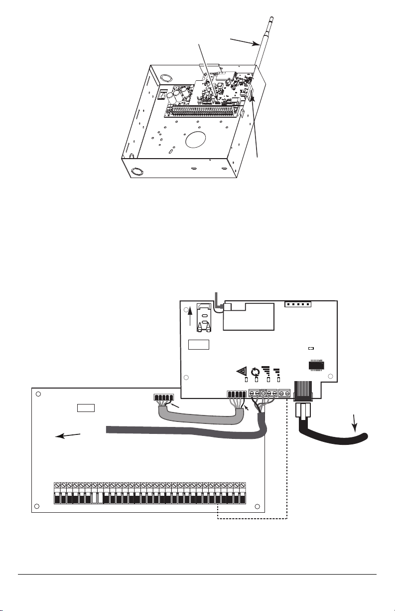
Figure 2: HS2016/2032/2064/2128 Control Panel
PC-Link
cable connector
screw
quad band
whip antenna
GSM Radio
RJ-45
UA601
Use light pressure
to attach antenna
nger tight only.
HS2016/2032/2064/2128
AUDIO/DEFAULT
DSC
UA601
PC-LINK
PCLINK_2
COM
TL2803G(R)
3G2080(R)
AC
AC
Z1 COM Z2 Z3 COM Z4 Z5 COM Z6 Z7 COM Z8
AUX+
BELL +
PGM1 PGM3
RING
T-1
HS2016/2032/2064/2128
3G Radio
UA621
To external antenna
Input Ratings:
+10.8V ~ +12.5 VDC
90mA(3G2080(R))/120mA(TL2803G(R)) standby;
400mA alarm
DSC Panel min. power requirements:
- 16.5 VAC 40 VA transformer;
- 12 VDC 7Ah battery
Red
Red
Jumper pins 4 and 5
to reset.
L
o
c
k
1
From NID
TL2803G(R)
Use only CAT5
Supervised
RJ-45
GRN
YEL
TIP
R-1
BLK
RED
AUX -
BELL -
EGND
TX+
GND
TX-
RX+
RX-
SHLD
SIM
Network Link
YELLOW
PGM2 PGM4
Maximum cable length
100 m (328 ft)
RS-232
To 3rd party device
WARNING! - 3G2080(R)/TL2803G (R) modules are power limited. Do not route any wiring over the circuit board. Maintain
at least 1in. (25.4mm) separation between circuit board and wiring. A minimum of ¼ in.(7mm) separation must be maintained at all points between non-powerlimited wiringand power limited wiring.
3.
To electrically connect the communicator to the panel, performthe following steps(See Figure 3).
a. Disconnectboth AC power and battery connections from the panel, and disconnect telephone line.
b. Confirm that the SIMcard is inserted in the holder and locked.
4. Install NetworkCable (TL2803G(R) only). Route the CAT5 Ethernet cable through back of the panel and plug itinto the
communicator’s RJ45 jack.
NOTE: Before leaving the premises the Ethernet communication lines mustfirst be connected to an approved (acceptable to
local authorities)type NID.All wiring shall be performed according to the local electrical codes.
Figure 3: Communicator Wiring Diagram
5. Install the RS-232 connections (Rmodels only).If using the communicator with a third partydevice, wire the connections
as per the table below:
7
Page 8

Table 3: RS-232 Connections
OR AND
ThirdParty Device Communicator
TX RX+
Unused RX-
RX TX+
Unused TX-
GND GND
6. Perform the following steps for initial power on ofthe panel with communicator installed:
a. Reconnect the AC power, telephone line, and battery +connector to the panel.
(The communicator and panel will power up together).
b. Observe that the communicator’s red and yellow LEDs are flashing together while it initializes. The red and yellow
LEDs will continue to flash untilthe communicator hassuccessfullycommunicated to all programmed receivers.If this
is the first time the communicator has been powered up in the panel, the module will initiate communication to C24
Communications to request remote programming.
NOTE: During radio reset,the two green LEDswill flash alternately.
NOTE: Initialization maytake several minutesto complete. Red and yellow LEDswill flash together during initialization. Do not
continue to nextstep until the red and yellow LEDs have stopped flashing. (If only the yellow LED is flashing, there is a
communicator trouble and the green LEDs are not valid for communicator placementtest). Correct trouble indicated by
flasheson yellow LED before continuing. (See Table 8 for troubleshooting assistance).
7. Perform the communicator placementtestbelow.
8. Mount the panel in final location indicated by placementtest.
Communicator Placement Test
3G2080(R) and TL2803G(R) only
To confirm that the cellular antenna location is suitable for radio operation, perform the placement testas follows:
NOTE: If radio signal strength istoo low,relocate the panel or install an optional extension antenna during thisprocedure.
1. Confirm that the yellow LED on the communicator is not flashing. A flashing yellowLED indicates trouble on the communicator.See Table 8 totroubleshoot and correctthe cause ofthis trouble before continuing to the next step.
2. Confirm that the strength of the radio signal on the yellow LEDand the 2 green LEDson the communicator meet or
exceed the minimumsignal level requirement. Minimum signal level: The yellow LED is OFFand the green LED 1 (furthestfrom the yellowLED) is ON(i.e.,not flashing) for the panel location to be acceptable. For interpretation ofreceiver
strength on LEDs, refer to the table “Radio Signal Strength”on page 10.
Cellular Signal Strength Display - LCD Keypad only
The cellular network signal strength can be checked on the keypad LCD screen by entering installer programming section
[850].The LCD will indicate the SIM card activation status followed by up to five bars of signal strength. Thisdisplay will automatically update every three seconds. For the relationship between signal strength bars, CSQ level, and signal level in dBm,
refer to“Radio Signal Strength”on page 10.
Table 4: Signal Strength Display
Description Display
SIM card active and current signal strength
SIM card inactive and current signal strength
Radio not registered
NOTE: If the required signal strength istoo low with the panel in its current location, the panel mustbe relocated or an external
antenna is required.
Ifrequired, the following cellular extension antenna kits are available to the installer:
l GS-15ANTQ - 4.57m (15’) internal antenna extension kit (suitable for interior mounting).
l GS-25ANTQ - 7.62m (25’) external antenna extension kit(suitable for interior/exterior mounting).
l GS-50ANTQ - 15.24m(50’) external antenna extension kit(suitable for interior/exterior mounting).
Specific instructionsfor the installation of the extension antenna are included with the kit. Observe all the electrical safety instructions regarding the installation of the antenna. All the wiring of the equipment shall be fully compliant with the local rules and
regulations.
8
Page 9

3. If required, install the antenna extension and perform the following stepsto determine the bestlocation for placement of
the antenna:
a. Disconnectthe whitewhip antenna from the panel.
b. Attach one end ofthe antenna extension cable to the threaded antenna connector on the panel and the other end to
the external antenna.
4. Move the extension antenna to various locationswhile observing the two green LEDs on the panel.
a. Continue to reposition the extension antenna until it receives an acceptable (minimumone green LED ON solid) sig-
nal strength.
NOTE: Minimum strength is: green LED 1 flashing and yellow LED off. If green LED 1 is flashing, relocation
b. Mount the supplied antenna extension bracket at the location that provides the bestsignal strength.
5. Alternately, reposition the panel to improve signal strength. Dismount the panel and move itto another location to
achieve the required signal strength.Ifthe panel is relocated to improve signal strength,mount itin the new location.
6.
When final panel/antenna location is determined, continue atthe Initial Panel Programming section.
NOTE: If the SIM card is notactivated, placement testwill indicate the signal strength ofthe nearest cellular tower.
NOTE: In between displaying signal strength, the signal strength LEDs will flash alternatelyif an inactive SIM card is used. The
should be considered.
flashing indicatesthat the module is attempting to attachto the cellular network and will only last briefly.
Initial Panel Programming
HS2016/2032/2064/2128 Initial Programming
Please refer to panel manual section ‘Alternate Communicator Set-up’ for details.
1.
In panel section [377] ‘Communication Variables’, subsection [002] ‘Communication Delays’, sub-subsection [1] ‘Communication Delay’, program 060 (seconds).
2.
In panel section [382] ‘Communicator Option 3’ set option [5] ON
3.
In panel sections[300] subsections [001] to [004], program the subsection with 02 to 06
Table 5: Communicator Path Programming
Value CommunicationMethod
02 Auto Routing
03 Ethernet 1
04 Ethernet 2
05 Cellular 1
06 Cellular 2
NOTE: Refer to panel manual for additional information
4.
In panel section [350] ‘Communication Formats’,program the communication format as: CID(03) or SIA FSK (04).
5.
In panel sections[311] - [318] ‘Partition Call Directions’, program the call direction options for the system.
6.
In panel section [401] ‘DLS/SA Options’,settoggle option [2]‘User Enable DLS’ to ONin order to perform panel DLS
session through cellular or Ethernet.
NOTE: Before leaving the premises, the installer should verify all programmed communications paths. See programming
options section [851][901] to send immediate testtransmissions.
Communicator Troubles displayed on a HS2016/2032/2064/2128
The communication trouble is the only trouble that will appear on the keypad Liquid Crystal Display (LCD) when encountered
by a communicator installed in a HS2016/2032/2064/2128. For more information about the trouble on the communicator module, refer to the panel eventbuffer or by accessing *2 to view the individual trouble types.
Communicator Status LEDs
The communicator has four on-board LED indicators. These include one yellow trouble LED, one red network connection
status LEDand two green signal strength LEDs. The LED meaning is described in thissection.
Yellow Trouble LED
This yellow LED will flash to indicate a trouble on the unit. The number of flashes indicates the type of trouble. See the table
below for the coded flashes and the conditions which will activate the trouble statusLED.
9
Page 10

Table 6: Yellow Trouble Status LED
# of
Flashes
Trouble
# of
Flashes
Trouble
2 Panel Supervision Trouble 8 Receiver Supervision Trouble
4 Not Applicable 9 FTC Trouble
5 Cellular Trouble 10 C24 CommunicationsConfiguration Failure
6 Ethernet Trouble 12 Module Configuration Trouble
7 Receiver Not Available Trouble
NOTE: Only the highest prioritytrouble (2 flashes is the highest priority trouble) is indicated. When this trouble is restored, the
next highest trouble will indicate, if present. This will continue until all troubles have been cleared (yellow LED is not
flashing).
Red Network Connection Status LED
TL2803G(R)
BLINKING:Indicatescommunicationsin progress.
l Once quicklyfor outgoing Ethernet transmission.
l Twice quicklyto indicate incoming Ethernet ACK/NACK.
OFF:This isthe normal state of the red networkconnection statusLED. There are no networkconnection issues present.
ON: There is a problem with the Ethernet or the cellular network connection. LED will be ON if any ofthe following occur: Eth-
ernet cable isnot connected, DHCP configuration timesout, unit fails to get an IP addressfrom the cellular network,or Cellular
connection hasbeen reset.
(Green LED 1) (Green LED 2) and (Yellow LED) Signal Strength
NOTE: If the yellow LED isflashing, signal strength in table below isnot valid.
See Table 8 for troubleshooting flashing yellow LED.
Table 7: Radio Signal Strength
Signal
Strength
CSQ
Level
Yellow
LED
Green
LED 2
Green
LED 1
Signal
Level
dBm
ActionRequired
If this status persists and the yellow LED shows 5
Radio Not
Ready
N/A N/A
Alternate
Flashing
Alternate
Flashing
flashes,confirm thatthe SIMcard isactive.
N/A
Confirm cellular service isactive in area.
Relocate panel or install external antenna.
No Signal 0 ON OFF OFF -108.8 Check all antenna connections.
1 Bar 1 - 4
Flashing
See Note
OFF Flashing
2 Bars 5 - 6 OFF OFF Flashing
-108 ~ 103
Relocate panel or install external antenna if yellow
trouble LED shows five flashes.
-102 ~ -
99
3 Bars 7 - 10 OFF OFF ON -98 ~ -91
4 Bars 11-13 OFF Flashing ON -90 ~ -85
5 Bars 14 + OFF ON ON
Location isOK. Cellular signal strength isgreater
than CSQ 7.
-84 and
higher
NOTE: The communicator will indicate cellular trouble (yellow LED = 5 flashes) if the calculated average CSQ Level is 4 or
less.The communicator signal strength can be viewed remotelywith C24 Communications.
Network Activity LEDs - Red and Green(TL2803G(R) only)
l
Ethernet Activity: Red LED will blink quickly once for transmit,or twice for receive.
l
CellularActivity: Green LED 2 will blink quickly oncefor transmit,or twice for receive
10
Page 11

Communicator Reset/Update
Factory Defaults Reset
Resetthe programming options for the communicator to the factory settings by installing the hardware jumper. Performthe following steps to resetthe communicator:
NOTE: A jumper is required on AUDIO/DEFAULTpins 4 and 5 to resetthe hardware values.
1. Remove panel frontcover.
2. Locate the AUDIO/DEFAULT5 pin connector on the communicator board (see Figure 3).
3. Apply a jumper to shortthe hardware default pins 4 and 5.
4. Remove AC and DC power from the panel and then reapply power to the panel.
5. Wait until the two green LEDson the communicator begin flashing rapidly.
6. Remove the jumper from the hardware default pins4 and 5 (green LEDs will stop flashing).
7. Replace the panel cover.
NOTE: The communicator has now been resetto the factory default values.
Firmware Update
The firmware ofthe device can be updated over cellular or Ethernet (remote or local updating):
l When the firmware update begins,all 4 LEDs are ON.
l During the firmware update process, the LEDs will cycle in a chaser pattern.
l During the firmware update process, the chaser pattern will briefly pause and resume again. This indicatesfirmware veri-
fication checkhas passed, and application update will begin.
l After a successful update,the unit will automatically restart.
l Should the update fail,all 4 LEDswill flash ON,then OFFtogether at 1 second intervals.
NOTE: If the firmware update fails,restart the communicator bycycling power. For persistent update failures, contact the dealer.
Communicator Troubleshooting
Table 8: Trouble Indications
Trouble indic-
ation
No Indication N/A No Power
Yellow LED
– ON Solid
Trouble LED
– 2 Flashes
Yellow LED
– 5 Flashes
Yellow LED
– 6 Flashes
Trouble
IndicatorDigit
Possible Causes Trouble Possible Solution
N/A No Signal
02
Supervision
05 Cellular Trouble
06 Ethernet Trouble
Panel
Trouble
l Checkthe power connections between the panel and the
communicator.
l Confirm PC-LINK cable isproperly installed between communicator
and panel.
l Confirm that cellular network service is active in the area.
l Ensure the antenna issecurely connected tothe radio. Check
antenna stub cable is securely connected to the radio.
l Ifan external antenna isused, ensure the antenna is securely
screwed on to the antenna cable connector.Check external antenna
for damage or open/short.
l Checksection [382] toggle option[5]is ON (Alternate Communicator
Enabled).
l Ensure the PC-LINK cable between the panel and communicator is
connected properly (notreversed) and is securely in place.
l Confirm that cellular service is available and active in the area.
l Checkall antenna connections.
l Ensure average radio signal strength isCSQ 5 or higher. (See Table
7 ).
l Ensure the SIM card is properly inserted into the SIMcard holder.
l Ensure the SIM card has been activated (could take up to 24 hrsafter
install).
l Ifthis trouble persists,relocate the panel (and communicator) or
install an external antenna extension kit.
l Checkwith the ISP to confirmInternet service isactivein the area.
l Ensure the Ethernet cable issecurely inserted into the RJ45 jack of
the communicator and the hub/router/switch.
l Checkthe link light on the hub/router/switch is ON. If link light isOFF,
startthe hub/router/switch.
l IfDHCP is used,ensure that the unit has an assigned IP address from
the server. In Section [851][992] verify a valid IP address is
programmed. Ifnot,contactthe network administrator.
11
Page 12

Trouble indic-
ation
Yellow LED
– 7 Flashes
Yellow LED
– 8 Flashes
Yellow LED -
9 Flashes
Yellow LED
– 12 Flashes
All LEDs
flashing
together
Red and
Yellow LEDs
flashing
together
Only Green
LEDs
flashing
Green LEDs
alternating
Trouble
IndicatorDigit
Possible Causes Trouble Possible Solution
07
08
09 FTCTrouble
0C
N/A
N/A
N/A
N/A
Hardware Default
Radio Initialization
Receiver Not
Available
Receiver
Supervision
Trouble
Module
Configuration
Trouble
Boot Loader
Failed
Initialization
Sequence
Jumper
Radio Resetor
l Ifproblem persists, replace the Ethernet cable and RJ45 connector.
l Ensure thatthe Ethernet path has Internet connectivity.
l Ifusing a staticIP address,confirm thatthe gatewayand subnet mask
are entered correctly.
l Ifthe network has a firewall, ensure the networkhas the programmed
outgoing ports open (defaultUDP port3060 and port 3065).
l Ensure thatall the receiversare programmed for DHCP or have the
proper IP address and port number.
l Ensure the cellular receiver APNshave been programmed with the
accesspoint name provided by the cellular provider.
l IfCommon Mode is used, and onlyone path is initialized while the
other path isnot successful,generate a manual test transmission over
both pathsor power cycle the communicator to recover the ‘Receiver
Not Available’ trouble.
l This trouble is indicated when supervision is enabled and the unit is
not able to successfully communicate with the receiver.
l Ifthis trouble persists,contactthe central station.
l The unit has exhausted all communicationsattempts to all
programmed receivers for eventsgenerated bythe communicator.
l Restart the system, if trouble persists,contact the dealer.
l This indication appears when section [021] system account code or
sections [101]; [111]; [201];and [211] receiver accountcode have not
been programmed. Ensure that a valid account code hasbeen
entered in thesesections.
l Disconnect power,then reconnectpower to the communicator
module.
l The unit is still initializing please wait while the unit gets its
programming and establishesa connection to all programmed
receivers.
NOTE: This processmay take several minutesto complete.
l The hardware default jumper is installed and mustbe removed.See
Figure 3.
l Ifthis status persistsand the yellow LED shows 5 flashes,confirm that
the SIMcard is active.
Ethernet/Cellular Programming Options
The programming sections described in this document can be viewed at the keypad LCD. To start programming enter: [*][8]
[installer code] [851] [section number], where section number is the 3-digit section number referenced in this section. The
programming worksheetsat the end ofthis document can be used to record the new values when programming changes have
been made fromthe default values.
12
Page 13

Ethernet Cellular Programming
Worksheets
System Options
[001] Ethernet IP Address
Default(000.000.000.000)
[002] Ethernet IP Subnet Mask
Default(255.255.255.000)
[003] Ethernet Gateway IP Address
Default(000.000.000.000)
[004] Receiver Supervision Interval
Default(0087/135) Valid range: 0000 - FFFF.
[005] System Toggle Options
[1]Ethernet Receiver 1 Supervised Default (OFF).
[2]Cellular Receiver 1 Supervised Default (OFF).
[3]Supervision Type Default (OFF).
[4]Primary Communications Path.
Default[OFF]TL2803G(R); [ON] 3G2080(R).
[5]Redundant Communications Default (OFF).
[6]Remote Firmware Upgrade Default (ON).
[7]Alternate TestTransmission Default (OFF).
[8]Cellular Low Signal Trouble Default(OFF).
[006] System Toggle Options 2
[1]Ethernet Receiver 1 Enabled Default(ON).
[2]Ethernet Receiver 2 Enabled Default(ON).
[4]Cellular Receiver 1 Enabled Default(ON).
[5]Cellular Receiver 2 Enabled Default(ON).
[7]DLS Over Cellular Default (ON).
[8]NetworkTrouble Suppression Default (OFF).
[007] DNS Server IP 1
Default(000.000.000.000)
Programming Options
[010] System Toggle Options 3
[1]Reserved
[2]Visual Verification Default (OFF).
[3]Reserved
[011] Installer Code
Default(CAFE) Valid range: 0000 - FFFF.
[012] DLS Incoming Port
Default(0BF6/3062) Valid range: 0000 - FFFF.
[013] DLS Outgoing Port
Default(0BFA/3066) Valid range: 0000 - FFFF.
[015] DLS Call-Up IP
Default(000.000.000.000)
[016] DLS Call-Up P ort
Default(0000) Valid range: 0000 - FFFF.
[020] Time Zone
Default(00) Valid range: 00 - 99.
[021] Account Code
Default(FFFFFF) Valid range: 000001 - FFFFFE.
[022] Communications Format
Default(04) Program 03 (CID),04 (SIA).
[023] Panel Absent Trouble
Default(FF); Program 00 disable or FF enable.
[024] Panel Absent Trouble Restore
Default(FF) Program 00 disable or FF enable.
[025] Radio Act ivation Restore
Default(FF) Program 00 disable or FF enable.
[008] DNS Server IP 2
Default(000.000.000.000)
[009] Language
Default(01); Program label language 01-29
System Test Options
[026] Ethernet 1 Transmission
Default(FF) Program 00 disable or FF enable.
[027] Ethernet 2 Transmission
Default(00) Program 00 disable or FFenable.
13
Page 14

[028] Cellular 1 Transmission
Default(FF) Program 00 disable or FF enable.
[029] Cellular 2 Transmission
Default(00) Program 00 disable or FFenable.
[030] FTC Restore
Default(FF) Program 00 disable or FF enable.
[037] Panel F irmware Update F ail
Default(FF) Program 00 disable or FF enable.
[095] SA Incoming Local Port
Default(0000) Valid range: 0000 - FFFF.
[096] SA Outgoing Local Port
Default(0000) Valid range: 0000 - FFFF.
[097] SA Call Up IP
Default(000.000.000.000)
[098] SA Call Up P ort
Default(0000) Valid range: 0000 - FFFF.
[099] SA Password
Default(FFFFFFFF) Valid range: 00000000 - FFFFFFFF.
[106] Ethernet Receiver 1 Domain Name
Default( ) 32 ASCII characters.
________________________________
Ethernet Receiver 2 Options
[111] Ethernet Receiver 2 Account Code
Default(0000000000)
Valid range: 0000000001 - FFFFFFFFFE.
[112] Ethernet Receiver 2 DNIS
Default(000000) Valid range: 000000 - 0FFFFF.
[113] Ethernet Receiver 2 Address
Default(000.000.000.000)
[114] Ethernet Receiver 2 UDP Remote Port
Default(0BF5/3061) Valid range: 0000 - FFFF.
[115] Ethernet Receiver 2 UDP Local Port
Default(0BF9/3065) Valid range: 0000 -FFFF.
[116] Ethernet Receiver 2 Domain Name
Default( )
____________________________________
Ethernet Options
[124] Ethernet Test Transmission Time
Default(9999) Valid: 00-23(HH);00-59(MM)
Ethernet Receiver 1 Options
[101] Ethernet Receiver 1 Account Code
Default(0000000000)
Valid range: 0000000001 - FFFFFFFFFE.
[102] Ethernet Receiver 1 DNIS
Default(000000) Valid range: 000000 - FFFFFF.
[103] Ethernet Receiver 1 Address
Default(127.000.000.001)
[104] Ethernet Receiver 1 UDP Remote Port
Default(0BF5/3061) Valid range: 0000 - FFFF.
[105] Ethernet Receiver 1 UDP Local Port
Default(0BF4/3060)Valid range: 0000 - FFFF.
[125] Ethernet Test Transmission Cycle
Default(000000)
Valid range: 000000 - 999999 minutes.
Cellular Receiver 1 Options
[201] Cellular Receiver 1 Account Code
Default(0000000000)
Valid range: 0000000001 - FFFFFFFFFE.
[202] Cellular Receiver 1 DNIS
Default(000000) Valid range: 000000 - 0FFFFF.
[203] Cellular Receiver 1 Address
Default(000.000.000.000)
[204] Cellular Receiver 1 P ort
Default(0BF5/3061) Valid range: 0000 - FFFF.
14
Page 15

[205] Cellular Receiver 1 APN Default ( )
32 ASCIIcharacters.
____________________________________
[206] Cellular Receiver 1 Domain Name
Default( )
32 Character ASCII characters.
____________________________________
Cellular Receiver 2 Options
[211] Cellular Receiver 2 Account Code
Default(0000000000)
Valid range: 0000000001 - FFFFFFFFFE.
[212] Cellular Receiver 2 DNIS
Default(000000)
Valid range: 000000 - 0FFFFF.
[213] Cellular Receiver 2 Address
Default(000.000.000.000)
[214] Cellular Receiver 2 P ort
Default(0BF5/3061) Valid range: 0000 - FFFF.
[215] Cellular Receiver 2 APN
Default( ) 32 ASCII characters.
____________________________________
[216] Cellular Receiver 2 Domain Name
Default( )
32 ASCIIcharacters.
____________________________________
Cellular Options
[221] Cellular Public Access P oint Name
Default( ) 32 ASCII characters
____________________________________
[222] Cellular Login User Name
Default( ) 32 ASCII characters.
____________________________________
[223] Cellular Login Password
Default( ) 32 ASCII characters.
____________________________________
[224] Cellular Test Transmission Time of Day
Default (9999) Valid range: 00 - 23 hrs. (HH) 00 - 59 min.
(MM).
[225] Cellular Test Transmission Cycle
Default(000000)
Valid range: 000000 - 999999 minutes.
[226] Net work Trouble Delay
Default(0F)
Valid entries from, 00 to FF.
Command and Control Options
[301] Command and Control Toggle Options
[1]SMS Notification (ON).
[2]Reserved
[3]SMS Command and Control Default (ON).
[4]Reserved
[5]SMS Character Format (OFF)
[6]Long SMS Message Handling Default (OFF).
[7]Reserved
[8]Reserved
[311]-[342] SMS Phone Number 1-32
______________________________________________
[343]-[374] SMS Phone Number 1-32 Toggle
Options
[1]SMS Notification Alarm/Restore Default(OFF).
[2]Reserved
[3]SMSNotificationOpening/ClosingDefault(OFF).
[4]Reserved
[5]SMS Notification SystemTestDefault(OFF)
[6]SMS Notification Internal EventsDefault (OFF).
[7]SMS Notification Enabled Default (OFF).
[8]SMS Command and Control Enabled Default
(ON).
[375]-[406] SMS Phone Number 1-32 Partition
Options
Default(00) Valid range: 00 - FF.
00 - Global; 01-32 - Partition; FF - Disabled
External Event Label Programming
[451] Burglary Alarm
Default(Burglary Alarm)
______________________________________________
[452] Burglary Alarm Restore
Default(Burglary Alarm Restore)
______________________________________________
[453] Fire Alarm
Default(Fire Alarm)
______________________________________________
[454] Fire Alarm Restore
Default(Fire Alarm Restore)
______________________________________________
15
Page 16

[455] 24 Hour Alarm
Default(24 Hour Alarm)
______________________________________________
[456] 24 Hour Alarm Restore
Default(24 Hour Alarm Restore)
______________________________________________
[457] Holdup Alarm
Default(Holdup Alarm)
______________________________________________
[458] Holdup Alarm Restore
Default(Holdup Alarm Restore)
______________________________________________
[459] Gas Alarm
Default(Gas Alarm)
______________________________________________
[460] Gas Alarm Restore
Default(Gas Alarm Restore)
______________________________________________
[461] High Temperature Alarm
Default(High Temperature Alarm)
______________________________________________
[462] High Temperature Alarm Restore
Default(High Temperature Alarm Restore)
______________________________________________
[463] Medical Alarm
Default(Medical Alarm)
______________________________________________
[464] Medical Alarm Restore
Default(Medical Alarm Restore)
______________________________________________
[465] Panic Alarm
Default(Panic Alarm)
______________________________________________
[466] Panic Alarm Restore
Default(Panic AlarmRestore)
______________________________________________
[467] Emergency Alarm
Default(EmergencyAlarm)
______________________________________________
[468] Emergency Alarm Restore
Default(EmergencyAlarm Restore)
______________________________________________
[469] Sprinkler Alarm
Default(Sprinkler Alarm)
______________________________________________
[470] Sprinkler Alarm Restore
Default(Sprinkler Alarm Restore)
______________________________________________
[471] Water Level Alarm
Default(Water Level Alarm)
______________________________________________
[472] Water Level Alarm Restore
Default(Water Level Alarm Restore)
______________________________________________
[473] Low Temperature Alarm
Default(Low Temperature Alarm)
______________________________________________
[474] Low Temperature Alarm Restore
Default(Low Temperature Alarm Restore)
______________________________________________
[475] Fire Supervisory
Default(Fire Supervisory)
______________________________________________
[476] Fire Supervisory Restore
Default(Fire Supervisory Restore)
______________________________________________
[477] CO Alarm
Default(CO Alarm)
______________________________________________
[478] CO Alarm Restore
Default(CO Alarm Restore)
______________________________________________
[479] Flood Alarm
Default(Flood Alarm)
______________________________________________
[480] Flood Alarm Restore
Default(Flood Alarm Restore)
______________________________________________
[481] Quick Bypass Alarm
Default(Quick BypassAlarm)
______________________________________________
[482] Quick Bypass Alarm Restore
Default(Quick BypassAlarm Restore)
______________________________________________
[483] Aux Alarm
Default(Aux Alarm)
______________________________________________
[484] Aux Alarm Restore
Default(Aux Alarm Restore)
______________________________________________
[485] Zone Expander Supervisory Alarm
Default(Zone Expander Supervisory Alarm)
______________________________________________
[486] Zone Expander Sup. Alarm Restore
Default(Zone Expander Sup. Alarm Restore)
______________________________________________
[487] Duress Alarm
Default(Duress Alarm)
______________________________________________
[500] Account Label
Default(Security System)
______________________________________________
[501] General System Tamper
Default(General System Tamper)
______________________________________________
[502] General System Tamper Restore
Default(General System Tamper Restore)
______________________________________________
16
Page 17

[503] General System Trouble
Default(General System Trouble)
______________________________________________
[504] General System Restore
Default(General System Restore)
______________________________________________
[505] Panel AC P ower Trouble Label
Default(AC Power Trouble)
______________________________________________
[506] Panel AC P ower Restore Label
Default(AC Power Restore)
______________________________________________
[507] Panel Auxiliary Power Trouble
Default(Auxiliary Power Trouble)
______________________________________________
[508] Panel Auxiliary Power Restore
Default(Auxiliary Power Restore)
______________________________________________
[509] Panel Batt ery Trouble
Default(Battery Trouble)
______________________________________________
[510] Panel Batt ery Restore
Default(Battery Trouble Restore)
______________________________________________
[511] Panel Bell Circuit Trouble
Default(Bell Circuit Trouble)
______________________________________________
[512] Panel Bell Circuit Restore
Default(Bell Circuit Restore)
______________________________________________
[513] Panel Telephone Line Trouble
Default(Telephone Line Failure)
______________________________________________
[514] Panel Telephone Line Restore
Default(Telephone Line Restore)
______________________________________________
[515] Fail t o Communicate Trouble
Default(Fail to Communicate Trouble)
______________________________________________
[516] Fail t o Communicate Restore
Default(Fail to Communicate Restore)
______________________________________________
[517] Fire Trouble
Default(Fire Trouble)
______________________________________________
[518] Fire Trouble Restore
Default(Fire Trouble Restore)
______________________________________________
[519] Zone Tamper
Default(Zone Tamper)
______________________________________________
[520] Zone Tamper Restore
Default(Zone Tamper Restore)
______________________________________________
[521] Zone Fault
Default(Zone Fault)
______________________________________________
[522] Zone Fault Restore
Default(Zone Fault Restore)
______________________________________________
[523] Alternate Communicator Trouble
Default(Alternate Communicator Trouble)
______________________________________________
[524] Alternate Communicator Restore
Default(Alternate Communicator Restore)
______________________________________________
[525] Module Trouble
Default(Module Trouble)
______________________________________________
[526] Module Trouble Restore
Default(Module Trouble Restore)
______________________________________________
[527] Wireless/AML Device Trouble
Default(Device Trouble)
______________________________________________
[528] Wireless/AML Device Restore
Default(Device Trouble Restore)
______________________________________________
[551] Disarmed By
Default(Disarmed By)
______________________________________________
[552] Armed By
Default(Armed By)
______________________________________________
[553] Disarmed
Default(Disarmed)
______________________________________________
[554] Armed
Default(Armed)
______________________________________________
[555] Automatic Disarming
Default(Automatic Disarming)
______________________________________________
[556] Automatic Arming
Default(Automatic Arming)
______________________________________________
[557] Automatic Arming Cancelled
Default(Automatic Arming Cancelled)
______________________________________________
[558] Late t o Open
Default(Late to Open)
______________________________________________
[559] Late t o Close
Default(Late to Close)
______________________________________________
[560] Disarmed After Alarm
Default(Disarmed After Alarm)
______________________________________________
17
Page 18

[561] Alarm Ocurred After Arming
Default(Alarm Ocurred After Arming)
______________________________________________
[562] Exit Fault
Default(Exit Fault)
______________________________________________
[563] Cold Start
Default(Cold Start)
______________________________________________
[564] Armed With Zones Bypassed
Default(Armed With Zones Bypassed)
______________________________________________
[565] Zone Bypassed
Default(Zone Bypassed)
______________________________________________
[566] Zone Unbypassed
Default(Zone Unbypassed)
______________________________________________
[567] Burglary Verified
Default(Burglary Verified)
______________________________________________
[568] Burglary Not Verif ied
Default(Burglary NotVerified)
______________________________________________
[569] Alarm Cancelled
Default(Alarm Cancelled)
______________________________________________
[570] Holdup Verified
Default(Holdup Verified)
______________________________________________
[571] Walk Test Begin
Default(Walk Test Begin)
______________________________________________
[572] Walk Test End
Default(Walk Test End)
______________________________________________
[573] System Test
Default(Test Message)
______________________________________________
[574] Periodic Test Transmission
Default(Periodic Test)
______________________________________________
[575] Periodic Test With Trouble
Default(Periodic Test With Trouble)
______________________________________________
[576] DLS Remote Programming Begin
Default(Remote Programming Begin)
______________________________________________
[577] DLS Remote Programming End
Default(Remote Programming End)
______________________________________________
[578] SA Remote P rogramming Begin
Default(Remote Programming Begin)
______________________________________________
[579] SA Remote P rogramming End
Default(Remote Programming End)
______________________________________________
[580] Installer Lead In
Default(Local Programming Begin)
______________________________________________
[581] Installer Lead Out
Default(Local Programming End)
______________________________________________
[582] Firmware Update Begin
Default(Firmware Update Begin)
______________________________________________
[583] Firmware Update Successful
Default(Firmware Update Successful)
______________________________________________
[584] Firmware Update Fail
Default(Firmware Update Fail)
______________________________________________
[585] Delinquency
Default(Delinquency)
______________________________________________
[586] Keypad Lockout
Default(Keypad Lockout)
______________________________________________
[587] Event buf fer 75% full
Default(Event Buffer Near Full)
______________________________________________
[591] FTC Trouble
Default(fail to communicate trouble)
______________________________________________
[592] FTC Restore
Default(fail to communicate restore)
______________________________________________
[593] Panel Absent Trouble
Default(Panel Communications Trouble)
______________________________________________
[594] Panel Absent Trouble Restore
Default(Panel Communications Restore)
______________________________________________
[595] Module Reprogramming
Default(Communicator Programming Updated)
______________________________________________
[596] Firmware Update
Default(Communicator Programming Updated)
______________________________________________
[600] Module
Default(Module)
______________________________________________
[601] Stay Arm
Default(Stay Arm)
______________________________________________
[602] Away Arm
Default(Away Arm)
______________________________________________
18
Page 19

[603] Night Arm
Default(Night Arm)
______________________________________________
[604] Disarm
Default(Disarm)
______________________________________________
[605] Act ivate Command Output 1
Default(ActivateCommand Output1)
______________________________________________
[606] Act ivate Command Output 2
Default(ActivateCommand Output2)
______________________________________________
[607] Act ivate Command Output 3
Default(ActivateCommand Output3)
______________________________________________
[608] Act ivate Command Output 4
Default(ActivateCommand Output4)
______________________________________________
[609] Deactivate Command Output 1
Default(Deactivate Command Output 1)
______________________________________________
[610] Deactivate Command Output 2
Default(Deactivate Command Output 2)
______________________________________________
[611] Deactivate Command Output 3
Default(Deactivate Command Output 3)
______________________________________________
[612] Deactivate Command Output 4
Default(Deactivate Command Output 4)
______________________________________________
[613] Bypass
Default(Bypass)
______________________________________________
[614] Unbypass
Default(Unbypass)
______________________________________________
[615] Status Request
Default(Status Request)
______________________________________________
[616] Alarm Memory Request
Default(Alarm Memory Request)
______________________________________________
[617] Help
Default(Help)
______________________________________________
[618] Pay As You Go Balance Request
Default(Balance Request)
______________________________________________
[619] Keypad Message
Default(Keypad Message)
______________________________________________
[621] Function Successful
Default(Successful)
______________________________________________
[622] Function F ailure
Default(Unsuccessful)
______________________________________________
[623] Invalid Command
Default(Invalid Command)
______________________________________________
[624] System St ay Armed
Default(Stay Armed)
______________________________________________
[625] System Away Armed
Default(Away Armed)
______________________________________________
[626] System Night Armed
Default(Night Armed)
______________________________________________
[627] System Disarmed Ready
Default(Disarmed Ready)
______________________________________________
[628] System Disarmed, Not Ready
Default(Disarmed NotReady)
______________________________________________
[629] System In Alarm
Default(is in Alarm)
______________________________________________
[630] Trouble Label
Default(Service is Required)
______________________________________________
[631] No Alarms in Memory
Default(No Alarms in Memory)
______________________________________________
[632] Pay As You Go Balance
Default(Pay as you go balance:)
______________________________________________
[633] Pay As You Go Message
Default(*123#)
______________________________________________
[634] Response Code
Default(Response Code)
______________________________________________
[651] Integration Identif ication Number
Default()
[652] Integration Access Code
Default()
[663] Integration Toggle Options 2
[1]Integration Over Serial Port (ON)
[2]Integration Over Cellular (OFF)
[3]Integration Over Ethernet (OFF)
[4]Reserved
19
Page 20

[5]Integration Protocol (ON)
[6]Reserved
[7]Reserved
[8]Reserved
[664] Integration Toggle Options 3
[1]UDP Polling (OFF)
[2]TCP Polling (OFF)
[3]Real-time Notification (OFF)
[4]Notification FollowsPool (OFF)
[5]Reserved
[6]Reserved
[7]Reserved
[8]Reserved
[665] Interactive P olling Interval in Seconds
Default(000A) Valid range: 0000 - FFFF.
System Information (Read Only)
[983] Firmware Update Diagnostics Section
[984] Communicator Status
[985] Radio Initialization Status
[987] Language Version
[988] DNS 1 IP Address
[989] DNS 2 IP Address
[990] Boot Loader Version
[991] Firmware Version
[992] Ethernet IP Address
[993] Ethernet Gateway Address
[693] Integration Server IP
Default(000.000.000.000)
[694] Integration Notification Port
Default(0C00/00372) Valid range: 0000 - FFFF.
[695] Integration Polling Port
Default(0C01/3073) Valid range: 0000 - FFFF.
[697] Integration Server DNS
32 ASCIIcharacters.
____________________________________
[698] Integration Outgoing Port
Default(0C04/3076) Valid range: 0000 - FFFF.
[699] Integration Incoming Port
Default(0BFF/3071) Valid range: 0000 - FFFF.
Receiver Diagnostic Testing
[901] Diagnostic Test Transmission
[1]Ethernet 1 Default (OFF).
[2]Ethernet 2 Default (OFF).
[3]Cellular 1 Default(OFF).
[4]Cellular 2 Default(OFF).
[994] Cellular IP Address
[995] SIM Number
____________________________________
[996] Cellular Telephone Number
This number is required for DLS and Firmware upgrades.
____________________________________
[997] IMEI Number
____________________________________
[998] MAC Address
System Reset Defaults
[999] Software Default
Default(99); Valid entries are 00,11 or 55
20
Page 21

DigitalSecurity Controls warran tsthe originalpurchase r that for a period of twelve months from the da teo f purchase, the prod uct shallbe f ree of defects in materials
and workmanship unde rnormaluse. D uring the warrant yperiod, D igitalSecurity Controlsshall, at itso ption, repair or replace any defective product upon retu rn of the
produ ctto its factory, at no charge for labo uran d materials.Any replacemen tan d/or repa ired pa rts are warrant edf or the remainder of the original warran tyor nine ty
(90) days,w hichever islonger. The original purchasermust promptlyn otifyDigitalSecurity Controls in writing that there is defect inmaterialor workmanship, such written
notice to be received in all events prior to expiration o f the warranty p eriod. There is absolutely no warranty on sof tware and all softwa re products are sold as a user
license unde rthe termso fth esoft ware license agree ment included with the produ ct. The Customer assumesallrespo nsibilityfo rthe prop erselection, installation, ope ration and maintena nceo fan yprod uctspurcha sed fromD SC. Customp rodu ctsa reonlywa rrante dto the extent that theyd ono tfu nction upo nde livery. Insuch cases,
DSC can replace orcred ita tits option.
International Warranty
The warrant yfor intern ationalcustomersisthe same asfor any customer withinC anada and the Un ited States, witht hee xception tha tDigital SecurityCo ntrolsshall not
be responsible fora nycustoms fees, taxes,o rVATtha tmay be due.
Warr anty Proce dure
To obtain service under this warranty, please ret urnthe item(s)in question to the p ointo f purchase. Allauth orized distributors and d ealersha ve a warran ty program.
Anyone returning goo ds to Digital Security Contro ls must first obtain an aut horization n umber. DigitalSecurity Controls will not accept any shipment wha tsoever f or
which priorau thorization hasno tb een obtained .
Conditions to Void Warranty
Thiswa rrantya pplies onlyto defe ctsin parts and workmanship relating to normaluse .It doesn otcover:
l d amage incurred insh ipping orhan dling;
l d amage caused byd isastersuch as fire, flood, wind, earthq uakeor lightning;
l d amage due to causesb eyond the controlof DigitalSecurityC ontrolssuch ase xcessive voltage ,mechan icalshock orwater damage ;
l d amage caused byu nautho rized attachment, alteration s, modifications orfore ign objects;
l d amage caused byp eriphera ls(un lesssuch periphera lswe re supplied byDigital SecurityCo ntrols);
l d efectscaused by failure to provide a suitable installation environment for the products;
l d amage caused byu se oft heprodu ctsfor purposes othert han those forw hich it wasdesigned ;
l d amage fromimproper maintenan ce;
l d amage arising out ofany other abuse, mishan dling orimprope rapp lication of the products.
Item s Not Cove red by Warranty
In addition to the itemswhich void the Warranty, the following items shallnot be covered byWarranty: (i)freight costt oth erep air centre; (ii)produ ctswhich are not identified withD SC's product label and lot number o rserialnu mber; (iii)p roducts disassembledor repa ired in sucha manne ras to adversely affect pe rformance or preven t
ade quate inspection ort esting t overifya ny warranty claim.Access cardsor tags ret urned forre placement und erwa rranty will be credited or rep laced at DSC's option.
Products not covered by th is warranty, or oth erwise ou tof warran tydue to a ge, misuse, or da mage shall be evaluated , and a repa ir estimate shallb e provided. N o
repair workwillbe pe rformed until a validpurchase orderis received fromth eCustomer and a Ret urnMerchan dise Authorisation number (RMA)isissued byDSC's Customer Service.
DigitalSecurity Controls’sliabilityforf ailure torepair the product unde rthisw arrantya ftera reasonab le number ofa ttemptsw illbe limited to are placement of the produ ct,
as the exclusive remedy for breach of warran ty. Under no circumstancesshall DigitalSecurity Cont rolsbe liable for any special, incidental,o r conseq uential damag es
based up onb reach ofw arranty, breach of contract, neg ligence, strictliability,or any other lega ltheo ry.Such damages include, but are n otlimited to, lossof profits, loss
of the produ ct oran y associated equ ipment, costo fcapital, costo fsubstitute orre placement e quipment, facilitiesor services,d own time, purchaser’stime, the claimsof
third parties,including customers, and injuryt opro perty.Th elaws o fsome jurisdictions limito rdo not allow the disclaimero fconseq uential damages. If the laws ofsuch a
jurisdiction applyto any claimby ora gainstD SC, the limitations and disclaimersco ntained here shallbe to the g reatest extent permitted bylaw. Some state sdo not a llow
the exclusion or limitation ofinciden talor consequential damages, sot hat the above mayno tap plyto you.
Disclaimer of War ranties
This war ra nty contai ns the entire wa rr anty and shall be in li eu of any and all other wa rr anties , whether expres sed or implied (incl uding all implie d
warr anties of mer chanta bility or fitness for a partic ular purpos e) And of al l other obligations or li abilitie s on the part of Digital Secur ity C ontrols
Digital Securi ty Control s neithe r assume s r espons ibility for, nor authorize s any other pe rson purporting to a ct on its be half to modify or to cha nge
this war ranty, nor to a ssume for it any other warr anty or lia bility c oncer ning this pr oduct.
This dis cla imer of warr antie s and li mited war ra nty ar e governe d by the la ws of the pr ovince of Ontario, Cana da.
DigitalSecurity Controlsre commends tha tth eentire system be completelyteste d on aregular basis. Howe ver, despite frequen t testing, and due to, but not limited to,
criminaltampering orelectricald isruption, itisp ossiblef orthis product to failto perform asexpe cted.
Installer’s Lockout
Anyp rodu ctsre turned to DSCwh ich havethe Installer’sLo ckout option ena bled and exhibit no other problemswillbe subject to aservice charge .
Out of Warr anty Repairs
DigitalSecurity Controlsw illat itsoption repairo r replace out-of -warrantyp roductsw hich are return edt o itsfactoryaccording to the following conditions. Anyone retu rning goods to DigitalSecurityCo ntrols must firsto btain an authorization number. D igitalSecurity Controlsw illnot accept a nyshipment wha tsoever for whichprior autho rization hasn otb een obtaine d.
Products which Digital Security Controls dete rmines to be repa irable will be rep aired and re turned. A set fee which Digital SecurityC ontrols has pred etermined an d
which may bere visedf romt imeto time, willbe charged fore achu nitrepaired.
Products which DigitalSecurity Con trolsd etermines not to be repa irable willbe replaced by the ne arestequivalent p roduct available at that time. The current market
priceo fth erep lacement produ ct willbe charged fore achreplacement unit.
EULA
IMPORTANT- READ CAREFULL Y: DSC Software purchased with or without Productsand Componen tsis copyrighte da nd is purchased und er the following license
terms:
ThisEnd -User License Agreement (“EULA”)isa legal agreement betw een You(th ecompa ny,individual oren tity who acquired the Software and any related Hardwa re)
and Digital SecurityCo ntrols,a division ofTyco Safety Products Canad aL td. (“DSC”),the manufacturer ofthe integra ted securitysystemsan dth ed eveloper oft he software and anyrelated produ ctso rcompone nts(“HARDWARE”)w hich You acquired.
If th e D SC softwa re p rodu ct (“SOFTWARE PRODU CT” or “SOFTWARE”) is inte nded to be accompanied by HARDWARE, an d is NOT accompan ied b y new
HARDWARE, You may no t use, copy o r install the SOFTWARE PRODUCT. The SOFTWARE PRODUCT includes comput er software, and may include associated
media, printed materials, and “online”o relectronic documentation .
Anysof tware provided along with the SOFTWAREPRODU CTth atis associated w ith asep arate end-user license agreemen tislicensed to You und erth ete rmsof t hat
license agree ment.
Byinstalling, copying, d ownloading , storing, accessing or otherwise using the SOFTWARE PRODUCT, You a gree un conditionally to be bound b y the terms of t his
EULA, even ift hisEUL Aisdee med to be amodification of any previous arrangemen tor contract. If You do not agree to the termsof this EULA, DSCisu nwilling to license
the SOFTWAREPROD UCTto You, and You have no right to use it.
SOFTWARE PRODUCT LICENSE
The SOFTWAREPRODU CTisp rotected bycopyright laws an dinte rnational copyright treaties, asw ellas othe rintellectual property laws and treaties. The SOFTWARE
PRODUCT islicensed ,no tsold.
1. GRA NT OF LICENSE Thi s EULA gr ants You the following r ights:
Limited Warranty
21
Page 22

Software Insta llation a nd Use - For each licenseYou acquire, You mayha ve onlyon ecop yof the SOFTWAREPRODUC Tinstalled.
Storage/N etwork Use - The SOFTWAREPRODU CT may not be installed, a ccessed, displayed, run, shared o r used concurren tlyo n or from differe nt computers,
including aworkstation, terminal orothe rdigital electronic de vice (“Device”).In other w ords,if You have several workstation s, You willha ve to acquire a license for each
workstation whe re the SOFTWAREwillbe used.
Bac kup Copy -You may make back-upcopies ofth eSOFTWAREPRODU CT,b utYou may onlyhave one copy per license installed at any given time. Youmay use the
back-up copy solely fora rchivalpu rposes. Except a sexpresslyprovided in thisEULA, You mayn oto therwise make copies oft he SOFTWAREPROD UCT,including the
printed materialsaccompanying the SOFTWARE.
2. DESCRIPTION OF OTHER RIGHTSAND LIMITATIONS
Limitations on Rev er se Engine eri ng, Decompila tion and D isasse mbly - You may n ot re verse eng inee r, decompile, or d isassemble the SOFTWARE
PRODUCT, except and o nlyto the extent that such activityis expresslypermitted b yapp licable law not withstan ding thislimitation. You may not make any changes o r
modificationsto th e Software, withou t the w ritten p ermission of a n officer of D SC. You may not re move an yp roprietary notices, marks or labels from the Softwa re
Product. You shallinstitute reasonab le measures to ensure compliance with the termsan dcon ditions of thisEULA.
Separa tion of Components - The SOFTWARE PRODUCT is licensed as a single p roduct. Its componen t parts may not be separat ed for use on more tha n one
HARDWAREu nit.
Single INTEGRATED PRODU CT - If You acqu ired thisSOFTWARE withH ARDWARE, then the SOFTWARE PRODUCT islicensed with the HARDWARE as a single
integra ted product. In thiscase, the SOFTWAREPRODUC Tmay onlybe used with the HARDWAREas setf orthin thisEUL A.
Rental -You may not rent, lease orlen dth eSOFTWAREPRODU CT.You mayn otmake ita vailablet oot hersor post iton a serveror web site.
Software Product Tr ansfe r - You may transfer allof Your rights under thisEULA on lyasp artof a permanent saleo rtransfero f the HARDWARE,p rovided You reta in
no copies, You transfer a llof the SOFTWARE PRODUCT (including allcompon ent parts,t hemed ia and printed materials, anyu pgrade sa nd thisEULA),and provided
the recipient ag rees to the terms of th is EULA. I f the SOFTWARE PRODUCT is an u pgrade, any transfer must also include a ll prior versions of t he SOFTWARE
PRODUCT.
Term ination - Withou t prejudiceto a nyoth errights, D SC may terminate thisEULA if You failto complyw ith the termsand conditionso fthis EULA. In such event, You
mustd estroyallcopies ofth eSOFTWAREPRODU CTan da llof itscompon ent parts.
Trade mar ks -Th isEULA does not grant You anyright sincon nection witha nytrad emarkso rservice marksof DSC orits supp liers.
3. COPYRIGHT
Alltitle and inte llectual prop erty rights in and t o the SOFTWARE PRODUCT (including b ut not limited t o any images, ph otograp hs, and t ext incorporated into th e
SOFTWAREPRODUCT), the accompanying printed materials, and any copies ofthe SOFTWARE PRODUCT, are owne dbyDSCo ritssup pliers.You mayn otco py the
printed materials accompanying the SOFTWAREPRODUC T. Alltitle an dinte llectual prope rtyrights in and to the conte nt which may be accessed thro ugh use of t he
SOFTWAREPRODUCT are the property of the respective con tent owner and maybe pro tected byap plicable copyright or other intellectual property lawsand t reaties.
ThisEULA grants You norightst ouse such content. Allrights not expresslygra nted unde rthisEUL Aare reserved byDSC and itssupp liers.
EXPORT RESTRICTIONS - You agree th atYou willnot export or re-expo rt the SOFTWARE PRODUC Tto a ny country, person, o rent ity subject to Cana dian expo rt
restrictions.
CHOICE OFL AW- ThisSoftwa re License Agreement isgo verned by the lawso fthe Provinceo fOnt ario, Canad a.
ARBITRATION -Alldisputes arising in conn ection with this Agreemen tshallb ed etermined by finalan db inding a rbitration ina ccordan ce withth eArbitration Act,a nd the
parties agree to be bound byth earbitrator’sd ecision. The place ofarbitration shallbe Toron to, Canad a,a ndthe langu age oft hearbitration shallbe English.
LIMITED WARRANTY
NO WARRA NTY - DSC PROVIDES THE SOFTWARE “AS IS” WITHOUT WARRANTY. DSC DOES NOT WARRANT THAT THE SOFTWARE WILL MEET YOUR
REQUIREMENTSOR THATOPERATIONOF THESOFTWAREWIL LBEU NINTERRUPTED OR ERROR-FREE.
CHAN GES IN OPERATING ENVIRON MENT - DSC sha llno t be responsiblefor pro blemscau sed by chang esin the op erating characteristicsof the HARDWARE, or
for problemsin the interaction of the SOFTWAREPRODUCT with non-DSC-SOFTWAREor HARDWAREPRODUC TS.
LIMITATION OF LIAB ILITY; WARRANTY R EFLECTS ALLOCA TION OF RISK - IN ANYEVENT, IF ANYSTATUTEIMPLIESWARRANTIESOR CONDI TIONS NOT
STATED IN TH IS LICENSE AGREEMENT, DSC’S ENTIR EL IABILITY UND ER ANY PROVISION OF THIS LICENSE AGREEMENT SHALL BE LIMITED TO THE
GREATER OF THEAMOUNT ACTUALLY PAID BY YOUTO L ICENSETHE SOFTWAREPRODU CT AND FIVECANADIAN D OLLARS(CAD$5 .00). BECAUSE SOME
JURISDICTI ONSDO NOTALLOW THE EXCLUSION OR LIMITATIONOF L IABILITYFOR CONSEQUENTIAL OR INCIDENTAL DAMAGES, THEABOVE LIMITATION
MAYNOT APPLYTOYOU.
DISCLAIMER OF WARRA NTIES - TH IS WARRANTY CONTAINS THE ENTIRE WARRANTY AND SHALL BE IN L IEU OF ANY AND ALL OTHER WARRANTIES,
WHETHEREXPRESSED OR IMPLIED (INCL UDING ALL I MPLIEDWARRANTIES OF MERCHANTABILITY OR FITNESS FOR APARTICU LAR PURPOSE) AND OF
ALL OTHER OBLIGATIONS ORL IABILITIES ON THE PART OF DSC. DSC MAKES NO OTHERWARRANTIES. DSC NEITHERASSUMESN OR AUTHORIZES ANY
OTHER PERSONPURPORTIN GTOACTON ITSBEHALF TOMOD8IFY ORTO C HANGETH ISWARRANTY,N ORTO ASSUMEFOR IT ANYOTHER WARRANTY OR
LIABILITY CONCERNING THISSOFTWAREPRODU CT.
EXCLUSIVE REMEDY AND LI MITATION OF WARR ANTY - UND ER NO CIR CUMSTANCES SHALL D SC BE L IABLE FOR ANY SPECIAL, INC IDENTAL,
CONSEQUENTIAL OR INDIRECT D AMAGES BASED UPON BREACH OF WARRANTY, BREACH OF C ONTRACT, N EGLIGENCE, STRICT L IABILITY, OR ANY
OTHER LEGAL THEORY. SUCH DAMAGES I NCLUDE, BUT ARE NOT LIMITED TO, L OSS OF PROFITS, LOSS OF TH E SOFTWARE PRODU CT OR ANY
ASSOCIATEDEQUIPMENT, COSTOF CAPITAL,C OSTOF SUBSTITUTE OR REPLACEMENT EQUIPMENT,FACIL ITIESOR SERVICES, DOWNTIME, PURCHASERS
TIME,THE CLAIMSOF THIRD PARTIES,IN CLUDING CUSTOMERS, AND INJURY TOPROPERTY.
DSC recommends that the entire systemb ecomplete lyte sted on a regularbasis.H owever, despite frequen tte sting, and due to, but not limited to, criminalta mpering o r
electricaldisruption, itis possible forth isSOFTWAREPRODUC Tto failto performa sexpecte d.
22
Page 23

23
Page 24

+HUHE\'6&GHFODUHVWKDWWKLVGHYLFHLV LQFRPSOLDQFH ZLWKWKH HVVHQWLDO
UHTXLUHPHQWVDQGRWKHUUHOHYDQWSURYLVLRQVRI'LUHFWLYH(&
7KHFRPSOHWH577('HFODUDWLRQRI&RQIRUPLW\FDQEHIRXQGDW
KWWSZZZGVFFRPOLVWLQJVBLQGH[DVS[
&=('6&MDNRY¿UREFHSURKODģXMHŀHWHQWRY¿UREHNMHYVRXODGXVHYģHPL
UHOHYDQWQ¯PLSRŀDGDYN\VPÝUQLFH(&
'$1'6&HUNO¨UHUKHUYHGDWGHQQHNRPSRQHQWHQRYHUKROGHUDOOHYLNWLJHNUDYVDPW
DQGUHEHVWHPPHOVHUJLWWLGLUHNWLY(&
'87+LHUELMYHUNODDUW'6&GDWGLWWRHVWHOLQRYHUHHQVWHPPLQJLVPHWGHHLVHQHQ
EHSDOLQJHQYDQULFKWOLMQ(&
),1'6&YDNXXWWDDODLWWHHQW¦\WW¦Y¦QGLUHNWLLYLQ(&ROHQQDLVHWYDDWLPXNVHW
)5(3DUODSU«VHQWH'6&G«FODUHTXHFHGLVSRVLWLIHVWFRQIRUPHDX[H[LJHQFHV
HVVHQWLHOOHVHWDXWUHVVWLSXODWLRQVSHUWLQHQWHVGHOD'LUHFWLYH(&
*(5+LHUGXUFKHUNO¦UW'6&GD¡GLHVHV*HU¦WGHQHUIRUGHUOLFKHQ%HGLQJXQJHQXQG
9RUUDXVHW]XQJHQGHU5LFKWOLQLH(&HQWVSULFKW
*5(˂˜˞˱ˬ˲˭˞ˮ˹˪˱ˬ˯ˤ'6&ˡˤ˨˻˪ˢ˦˹˱˦˞˲˱˛ˤ˰˲˰˧ˢ˲˛ˢ˜˪˞˦˰˺˩˳˶˪ˤ˩ˢ˱˦˯
ˬ˲˰˦˻ˡˤ˯˞˭˞˦˱˛˰ˢ˦˯˧˞˦˩ˢ˹˨ˢ˯˱˦˯˙˨˨ˢ˯˰˴ˢ˱˦˧˚˯˞˪˞˳ˬˮ˚˯˱ˤ˯ˍˡˤˠ˜˞˯(&
,7$&RQODSUHVHQWHOD'LJLWDO6HFXULW\&RQWUROVGLFKLDUDFKHTXHVWRSURGRWWRª
FRQIRUPHDLUHTXLVLWLHVVHQ]LDOLHGDOWUHGLVSRVL]LRQLULOHYDQWLUHODWLYHDOOD'LUHWWLYD
&(
125'6&HUNO¨UHUDWGHQQHHQKHWHQHULVDPVYDUPHGGHJUXQQOHJJHQGHNUDYRJ
ºYULJHUHOHYDQWHNUDYLGLUHNWLY()
32/'6&RĝZLDGF]DľHXU]ÇG]HQLHMHVWZ]JRGQRĝFL]]DVDGQLF]\PLZ\PDJDQLDPL
RUD]SR]RVWDĄ\PLVWRVRZQ\PLSRVWDQRZLHQLDPL'\UHNW\Z\:(
3253RUHVWHPHLRD'6&GHFODUDTXHHVWHHTXLSDPHQWRHVW£HPFRQIRUPLGDGH
FRPRVUHTXLVLWRVHVVHQFLDLVH RXWUDVGHWHUPLQD©·HVUHOHYDQWHVGD 'LUHFWLYD
(&
63$3RUODSUHVHQWH'6&GHFODUDTXHHVWHHTXLSRHVW£HQFRQIRUPLGDGFRQORV
UHTXLVLWRVHVHQFLDOHV\RWURVUHTXLVLWRVUHOHYDQWHVGHOD'LUHFWLYD(&
6:('6&EHNU¦IWDUK¦UPHGDWWGHQQDDSSDUDWXSSI\OOHUGHY¦VHQWOLJDNUDYHQRFK
DQGUDUHOHYDQWDEHVW¦PPHOVHUL'LUHNWLYHW(&
290 094 32 R001
The trade marks,logo s, and servicemarksd isplayed on thisdocumen tare registered in the United State s[or other countries]. Anymisuseo fthe trad emarksis strictly prohibited and Tyco willagg ressively enfo rce its intellectualp rope rty rights to the fullestextent of the law ,including p ursuit of criminal prosecution w herever necessary. All
trade marksno tow ned byTyco are the property oft heirrespective owners,a nda reused withpermission orallowed undera pplicable laws.
Product offerings and specifications are subject to chan ge withou tno tice. Actual products mayvaryfromph otos. Not allprodu ctsinclude allfe atures. Availabilityvariesb y
region; conta ct your salesrepre senta tive.
© 2015 Tyco SecurityProducts.All Rights Reserved.
Tech Support:1-800-387-3630 (Canada & U.S.) or 905-760-3000
www.dsc.com
24
 Loading...