

Page 1
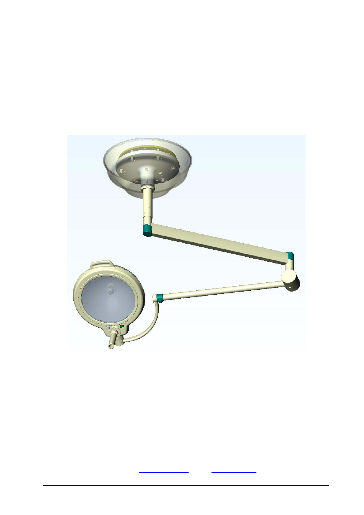
Ceiling attachment for Mach M2
Mounting instructions Directions for use
CEILING ATTACHMENT
FOR MACH M2
Dr. Mach
Lamps and Engineering
Ceiling lamps:
Dr. Mach
59860005 Edition 03 24.10.2006 / Bak Page 1/20
Mach M2................................
Mach M2 F.............................
GmbH u. Co., Flossmannstrasse 28, D-85560 Ebersberg
Tel.: +49 (0)8092 2093 0, Fax +49 (0)8092 2093 50
Internet: www.dr-mach.com, E-mail: [email protected]
Order No. 170 120 3330
Order No. 170 230 3330
Page 2

Ceiling attachment for Mach M2
Dr. Mach
Lamps and Engineering
List of contents
1. Safety instructions ............................................................................................................. Page 4
2. Mounting layout ceiling lamps ........................................................................................... Page 5
3. Ceiling attachment.............................................................................................................Page 6
3.1 Preparatory work on the ceiling.................................................................................. Page 6
3.1.1 Setting the safety dowels ................................................................................... Page 6
3.1.2 Mounting the ceiling anchorage ring
to the solid ceiling .............................................................................................Page 6
3.2 Pre-assembly of the ceiling flange and suspension tube........................................... Page 7
3.3 Mounting the flange and the suspension tube to the ceiling...................................... Page 8
3.4 Min. roomheights for ceiling attachments...................................................................Page 9
4. Electrical connection.......................................................................................................... Page 10
4.1 Preparing the electrical connection ............................................................................ Page 10
4.2 Position of transformer – Dr. Mach lamps.................................................................. Page 11
4.3 Wiring diagrams ......................................................................................................... Page 11
4.4 Ceiling lamps with external transformer ..................................................................... Page 11
5. Mounting the articulated arms and the lamp head ............................................................ Page 12
5.1 Mounting the articulated arms to the suspension tube ..............................................Page 12
5.2 Mounting the lamp to the spring arm.......................................................................... Page 13
6. Cleaning ............................................................................................................................Page 14
7. Maintenance ...................................................................................................................... Page 15
7.1 Periodical maintenance work ..................................................................................... Page 15
7.2 Adjusting the spring force........................................................................................... Page 15
7.3 Maintenance of the segment...................................................................................... Page 16
8. Data ...................................................................................................................................Page 16
8.1 Technical data ............................................................................................................ Page 16
8.2 Environmental conditions ...........................................................................................Page 16
9. Disposal............................................................................................................................. Page 17
10. CE- mark .........................................................................................................................Page 17
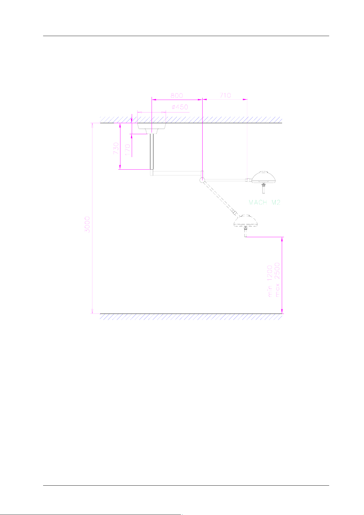
11. Dimensions and range of movement............................................................................... Page 18
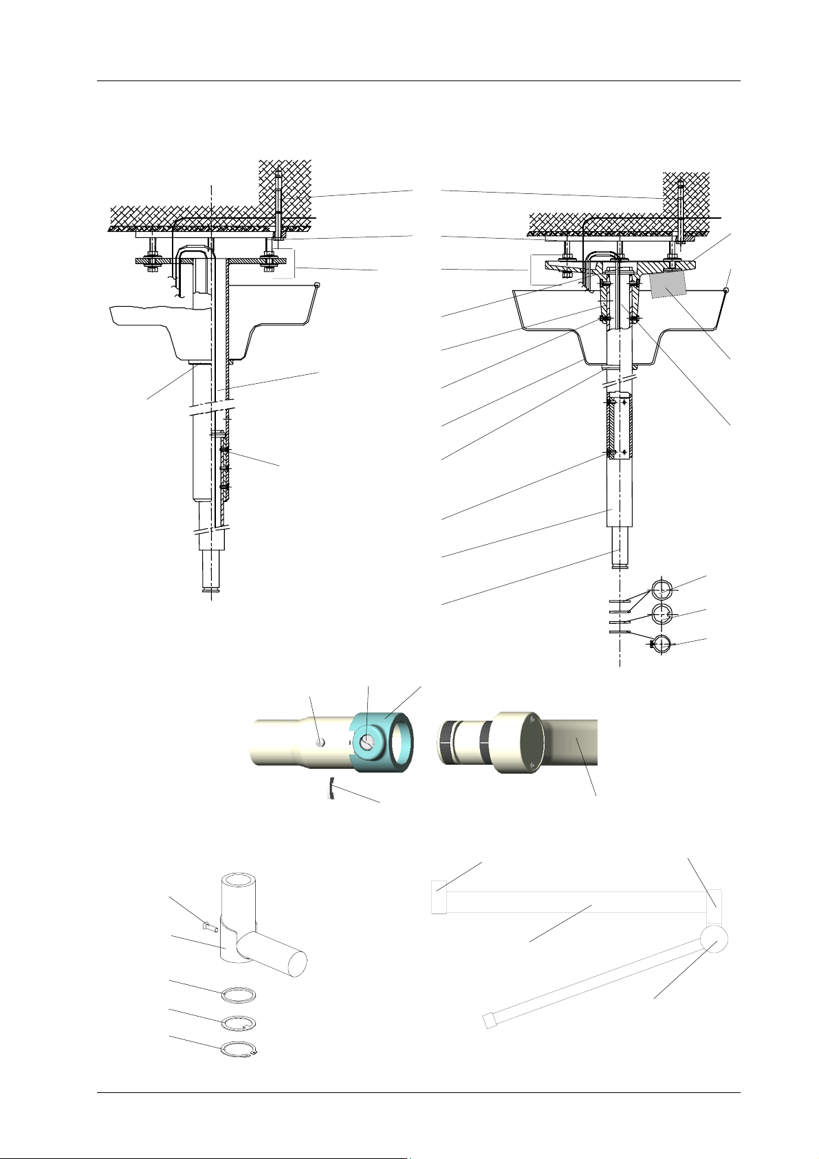
12. Spare parts ...................................................................................................................... Page 19
13. Spare parts list................................................................................................................. Page 20
59860005 Edition 03 24.10.2006 / Bak Page 2/20
Page 3

Ceiling attachment for Mach M2
Dr. Mach
Lamps and Engineering
Static inspection
Note:
The static (structural) inspection must be carried out before the installation of the
ceiling or wall anchorage!
- The strength of the construction must be designed, checked and certified by a structural
engineer.
- The respective regional construction regulations that apply must be followed.
- If a wrong hole is drilled by mistake, e.g. drilling of a reinforcement rod, the structural
engineer who is responsible must be contacted, since adequate static load distribution in the
ceiling may have been endangered.
Declaration of acceptance:
It is hereby certified that the supporting ceiling / wall and the ceiling anchoring / wall anchoring
is safe and adequately strong.
Project: ____________________________________________________________________
____________________________________________________________________________
____________________________________________________________________________
Anchoring (please check the one that is applicable)
- with dowels authorized by construction authority
- with counter-plate
- other
Location: ____________________________________________
Signature / Stamp: (structural engineer / construction authority)
59860005 Edition 03 24.10.2006 / Bak Page 3/20
Page 4

Ceiling attachment for Mach M2
Dr. Mach
Lamps and Engineering
1. Safety instructions
The lamp must not be connected to the mains, until it has been fully assembled and installed.
This device is not suitable for use in hazardous locations.
The devices are not suitable for use in combustible blends of anaesthesia agents with oxygen
or nitrous oxide.
Repairs to the ceiling attachment and special installation work on the sliding contacts should
only be carried out by ourselves or a company expressly authorised by ourselves.
The manufacturer is only responsible for operational safety of the ceiling attachment when
repairs and modifications are carried out by his own staff or by persons who guarantee
compliance with the safety regulations.
The manufacturer is not responsible for damage to persons or property caused by incorrect or
improper use, or when used for incorrect purposes.
General information
These installation instructions must be kept at hand together with the relevant
operating instructions for consultation at any time.
All Dr. Mach lamps are supplied with a flange with
a graduated circle diameter 270mm and six bores
diameter 15mm. The flange supports the vertical
suspension tube. It is attached to the solid ceiling
by means of a ceiling anchorage ring.
Remark: The ceiling anchorage ring has to be
ordered separately!
The ceiling anchorage ring has six precisely
positioned threaded bolts M12. It makes it possible
to fasten and adjust the lamp without causing dust
or dirt after all building work has been completed.
The use of a ceiling anchorage ring is necessary in
all cases of ceiling attachments.
During mounting, take care to ensure that neither
the flange nor the attachment elements are in
contact with reinforcement components of the solid
ceiling.
In view of the slight weight of the Dr. Mach lamps,
it is not fundamentally necessary to drill through
the ceiling and use a counter-plate. Ceiling
anchorage rings can be attached without any
problems to ceilings in the concrete strength class
greater than or equal to B25, using safety dowels
M8.
The forces arising when the widely extending
articulated arms tilt, do make it necessary to drill
very carefully with a certified hammer drill, paying
close attention to the drilling tolerances.
The suspension tube of the lamp must be adjusted
vertically to prevent the lamp body from moving.
For this purpose the M12 counter nuts on the
attaching bolts must be adjusted accordingly.
In case of false ceilings, the suspension tubes for
all lamps can be mounted directly through to the
solid ceiling. The opening required for this purpose
can be closed once the work has been completed,
using the canopy diameter 450mm or a covering
plate.
When using an intermediate flange (preferably for
spaces exceeding 400mm and for room heights
exceeding 4050mm), the length of the intermediate
flange is to be measured to the lower edge of the
false ceiling.
Also in this case a ceiling anchorage ring has to be
used for fixation.
59860005 Edition 03 24.10.2006 / Bak Page 4/20
Page 5
Ceiling attachment for Mach M2
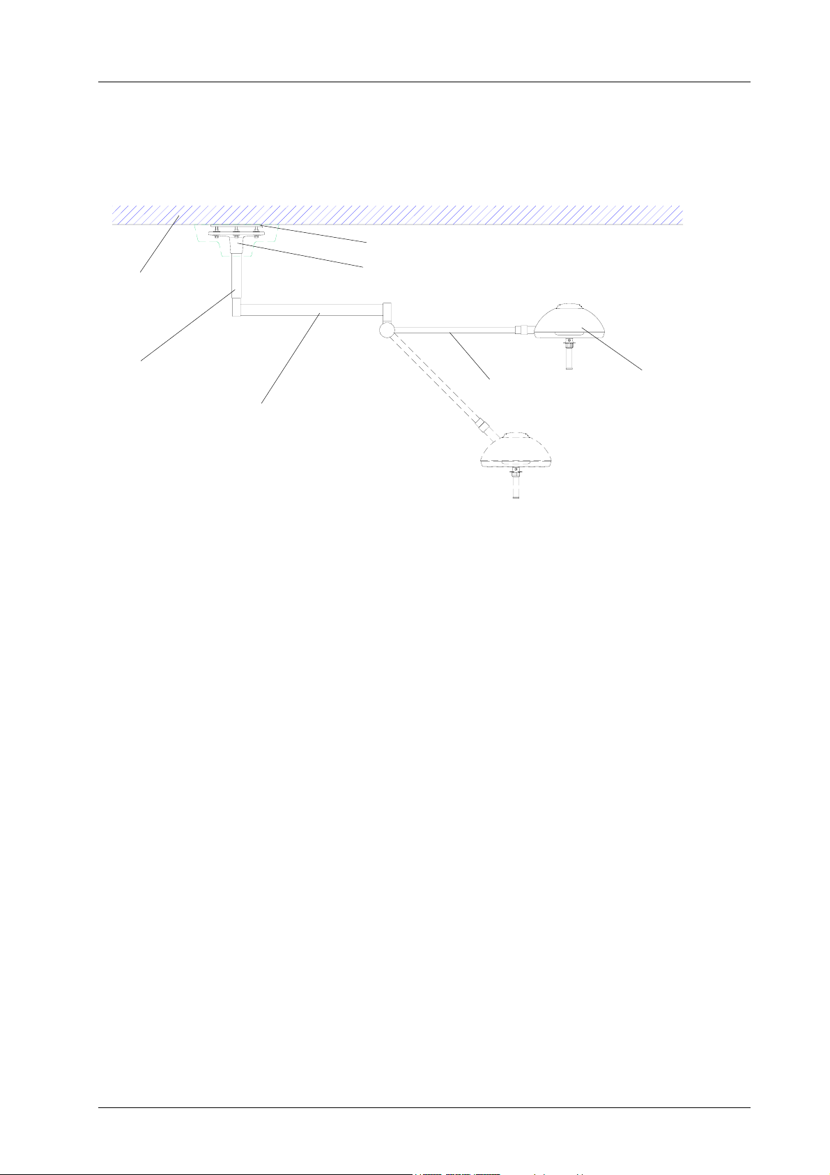
2. Mounting layout ceiling lamps
Mach M2; Mach M2 F
Concrete ceiling
Dr. Mach
Lamps and Engineering
Ceiling anchorage ring
Flange
Suspension tube
Horizontal arm
Spring arm
Lamp
59860005 Edition 03 24.10.2006 / Bak Page 5/20
Page 6
Ceiling attachment for Mach M2
Dr. Mach
Lamps and Engineering
3. Ceiling attachment
3.1 Preparatory work on the ceiling
3.1.1 Setting the safety dowels
Attention:
Lamps, ceiling anchorage rings and intermediate flanges may only be attached to a ceiling of
concrete strength class greater than or equal to B25. In case of light-weight ceiling coverings,
the dowel anchor must be sunk completely into the concrete. To bridge this space use long
threaded bolts for attaching the ceiling tube.
In addition, take care that neither suspension tube nor attaching elements come into contact
with reinforcement components of the solid ceiling.
The lamp weight and the tilt of the long articulated arm(s) require that this work is performed
meticulously. This refers particularly to the use of a certified hammer drill and to observe the
drilling tolerances.
3.1.2 Mounting the ceiling anchorage ring to the solid ceiling
The scope of supply includes:
1 attachment set, consisting of:
• Six safety dowels Fischer FHA 12/50 galZn
• Mounting data Fischer
• Bore template
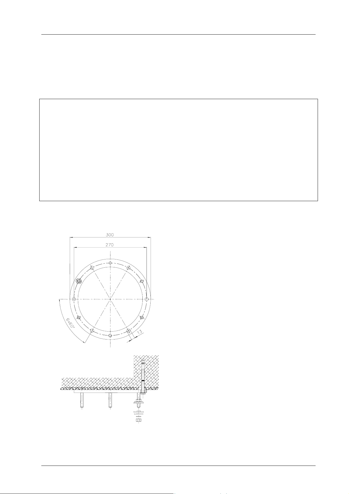
To attach the ceiling anchorage ring to a solid
ceiling proceed as follows:
• Drill the bore holes according to the figure
diameter 12mm and at least 100mm deep with
a certified hammer drill, using the enclosed
bore template. You can also use the ceiling
anchorage ring as a template. In this case a
second person may be needed to assist.
• Insert the safety dowels through the bores of
the ceiling anchorage ring in such a way, that
the washers lie flat to the ring.
• Tighten the screws carefully using a torque
wrench (25Nm).
Light-weight ceiling panelling with a maximum
thickness of 30mm can be bridged using the
enclosed safety dowels. For panelling thicker than
30mm, it is necessary to remove the panelling
before mounting.
59860005 Edition 03 24.10.2006 / Bak Page 6/20
Page 7
Ceiling attachment for Mach M2
Dr. Mach
Lamps and Engineering
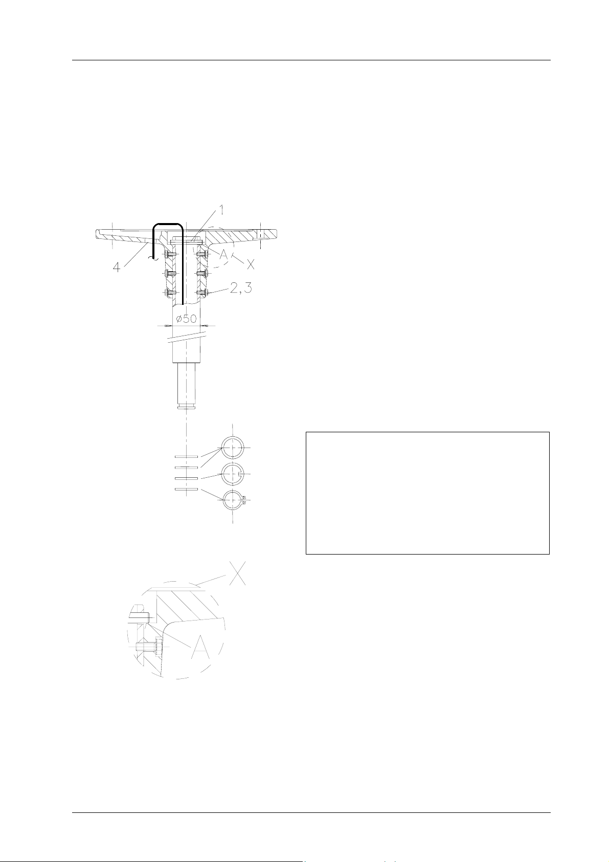
3.2 Pre-assembly of the ceiling flange and suspension tube
and installing the electrical connections
The length of the suspension tube is adjusted to the required room height with a clearance height of at
least 200cm under the lamp.
Aluminium cast flange and suspension tube ∅ 50mm
Standard version
For pre-assembly of ceiling flange and suspension
tube proceed as follows:
• Cable or cord showing out the suspension tube is
to be pushed carefully into the ceiling flange
together with the suspension tube.
• Push the suspension tube upwards until the
safety pin 1 can be pushed through the cross
bores of the suspension tube.
• Then pull the suspension tube down until the
safety pin 1 lies in recess A of the ceiling flange.
• Then secure the connection with six screws 2
and washers 3 to prevent wobbling.
If not possible, turn suspension tube by 180°.
• Pull the cable or cord through the bore 4 as
shown in the diagram.
Attention:
The suspension tube is delivered with
premounted retaining ring for the ceiling
canopy.
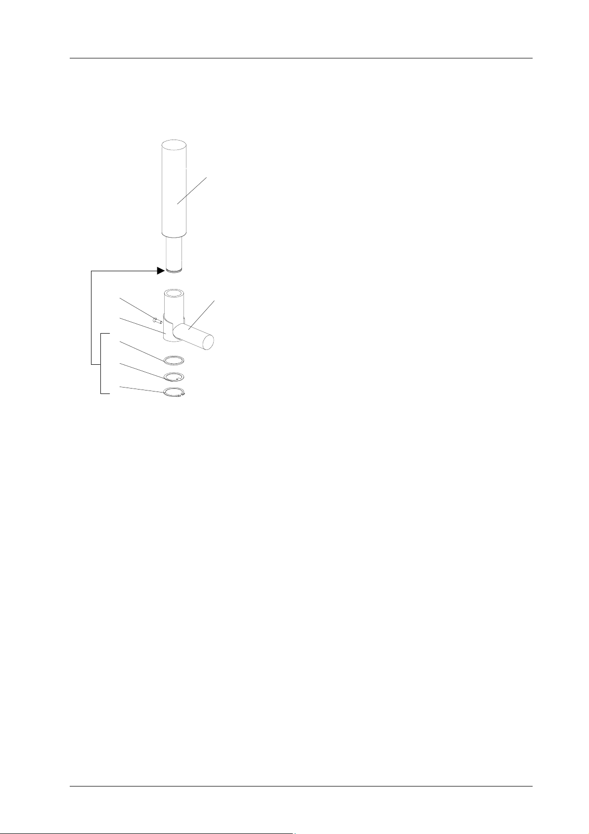
Each connection journal is also equipped with:
• 2 spacer rings;
• 1 gib ring;
• 1 circlip (Seegerring).
59860005 Edition 03 24.10.2006 / Bak Page 7/20
Page 8
Ceiling attachment for Mach M2
Dr. Mach
Lamps and Engineering
3.3 Mounting the flange and suspension tube to the ceiling
Before mounting the flange and the suspension tube, assembly work on the ceiling (setting the dowels or
mounting the ceiling anchorage ring and possibly mounting the intermediate flange) must be completed
and all pre-assembly work finished.
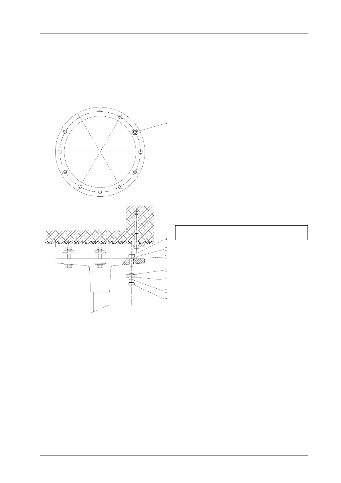
Type with ceiling anchorage ring
• Screw three nuts B (each 120°) to the plate of
the ceiling anchorage ring, holding the other
three nuts 0,5cm away from the plate, unscrew
nuts A.
• Position six washers C and six insulating
washers D on the flange.
• Position the flange with suspension tube on the
threaded bolts and adjust it to the required
height using three nuts A and washers C,
insulating washers D, and retaining washers E
(each 120°).
Note: Washers C, insulating washers D and
retaining washers E must be put on the
flange in the same order as shown in the
figure.
• The three-point mounting allows a simple
vertical adjustment of the suspension tube.
Vertical adjustment is very important and
must be carried out with great care.
If the flange with suspension tube is not in the
correct vertical setting, the support arms of the lamp
do not remain precisely in the proper position, they
could turn away and would therefore require
excessive braking.
• Then position from above all six nuts B gently
against the flange.
• Screw on the remaining three nuts A with
washers C, insulating washers D and retaining
washers E and tighten all six nuts equally
cross-wise with a torque wrench (25 Nm).
Note: Washers C, insulating washers D and
retaining washers E must be put on the
flange in the same order as shown in the
figure.
• Verify balance with a spirit-level.
59860005 Edition 03 24.10.2006 / Bak Page 8/20
Page 9
Ceiling attachment for Mach M2
3.4 Minimum room heights for ceiling attachments
Mach M2; Mach M2 F
Dr. Mach
Lamps and Engineering
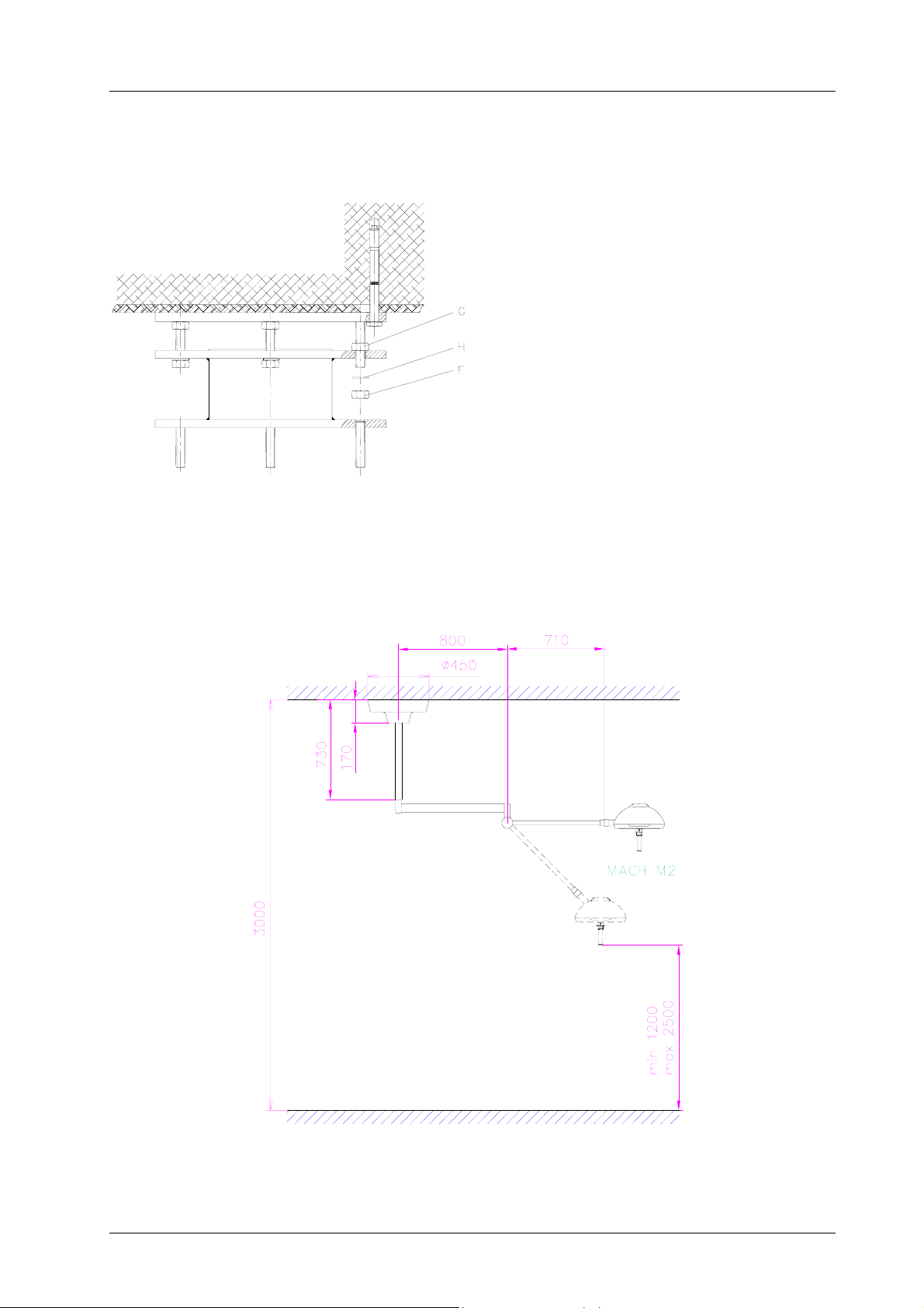
Type with ceiling anchorage ring and
Intermediate flange
• Screw three nuts G (each 120°) to the plate of
the ceiling anchorage ring, the other three 1cm
away from the plate, unscrew nuts F.
• Position the intermediate flange on the
threaded bolts and adjust it to the required
height using three nuts F and washers H.
• Then position all six nuts G gently against the
intermediate flange from above.
• Screw on the remaining three nuts F with
washers H and tighten all six nuts equally
cross-wise with a torque wrench (25 Nm).
• Verify balance with a spirit-level.
For mounting the flange to the intermediate
flange proceed as described at the design with
ceiling anchorage ring.
59860005 Edition 03 24.10.2006 / Bak Page 9/20
Page 10
Ceiling attachment for Mach M2
p
Dr. Mach
Lamps and Engineering
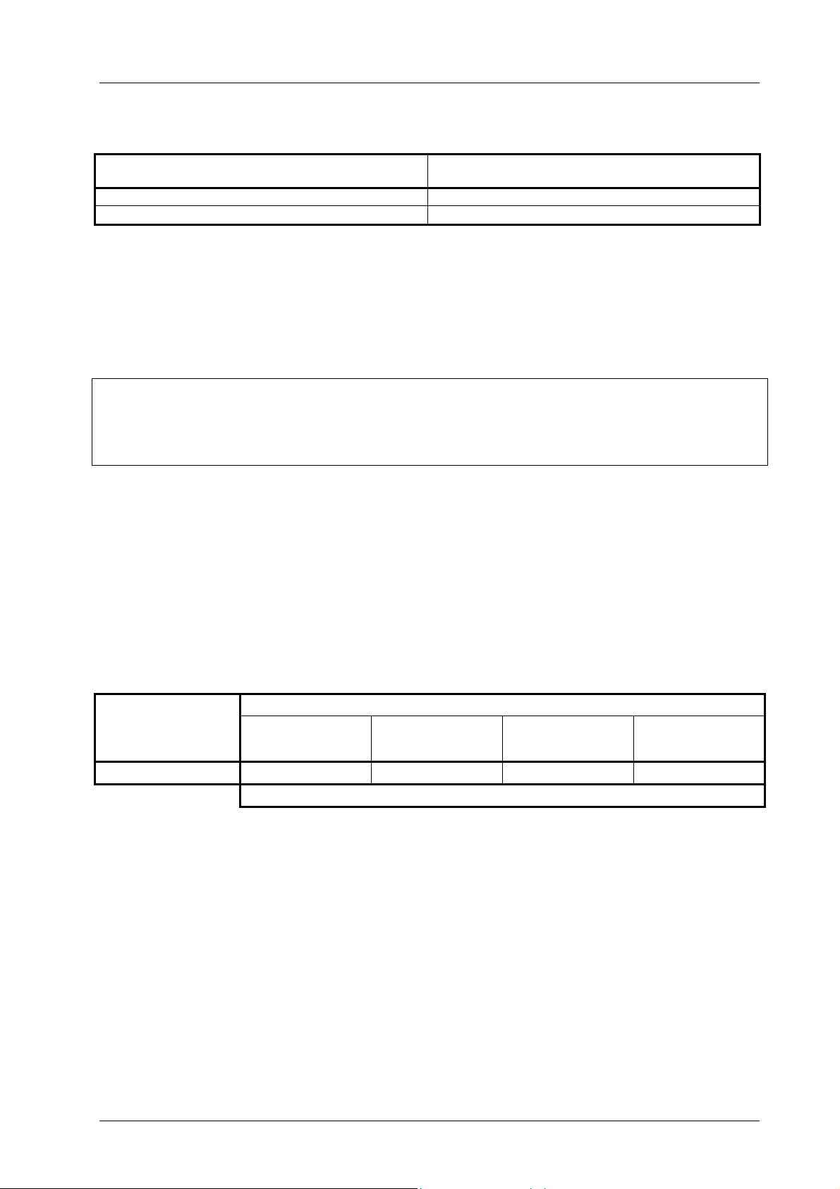
Room heights H – single ceiling lamps
Lamps
Mach M2 2420
Mach M2 F 2420
* Min. room height in the case of ceiling attachment with shortest suspension tube (180mm) for a
passing height of 2 meters
ending on ceiling attachment
de
Hmin*
4. Electrical connection
4.1 Preparing the electrical connection
Extent of supply:
• Cable on the suspension tube
• Line clamps on the flange
Put the cable through the flange. Ensure that the cables are cut to a length which allows approx. 15cm
cable to extend from the suspension tube.
The flange is fitted with line clamps for connecting the light system to the electrical circuit. These clamps
should be accessible for electrical safety checks during installation and also later.
Connect the mains supply and the cable from the suspension tube to the line clamps.
In case of lamps with external transformer the cross-sections of the cables must be designed in
accordance to the cable-length and power consumption.
The following table shows the recommended cross-sections:
Power consumption
[W]
up to 10 up to 20 up to 40 up to 70
Lead length [m]
80 2,5 4 10 16
Once the electrical connections have been completed, check that the system functions correctly in a noload operation trial run.
When connecting to an external transformer, the emerging voltage U will be approx. 10-20% above rated
voltage because of no load and anticipated lead losses. There is no point in making any adjustments until
the lamps have been completely mounted.
59860005 Edition 03 24.10.2006 / Bak Page 10/20
Cross-section of lead [mm
2
]
Page 11
Ceiling attachment for Mach M2
Dr. Mach
Lamps and Engineering
4.2 Position of transformer – Dr. Mach lamps
Lamps External transformer
Mach 120 / 120F X* Inside the wall bearing
Transformer
in the lamp housing
Remark
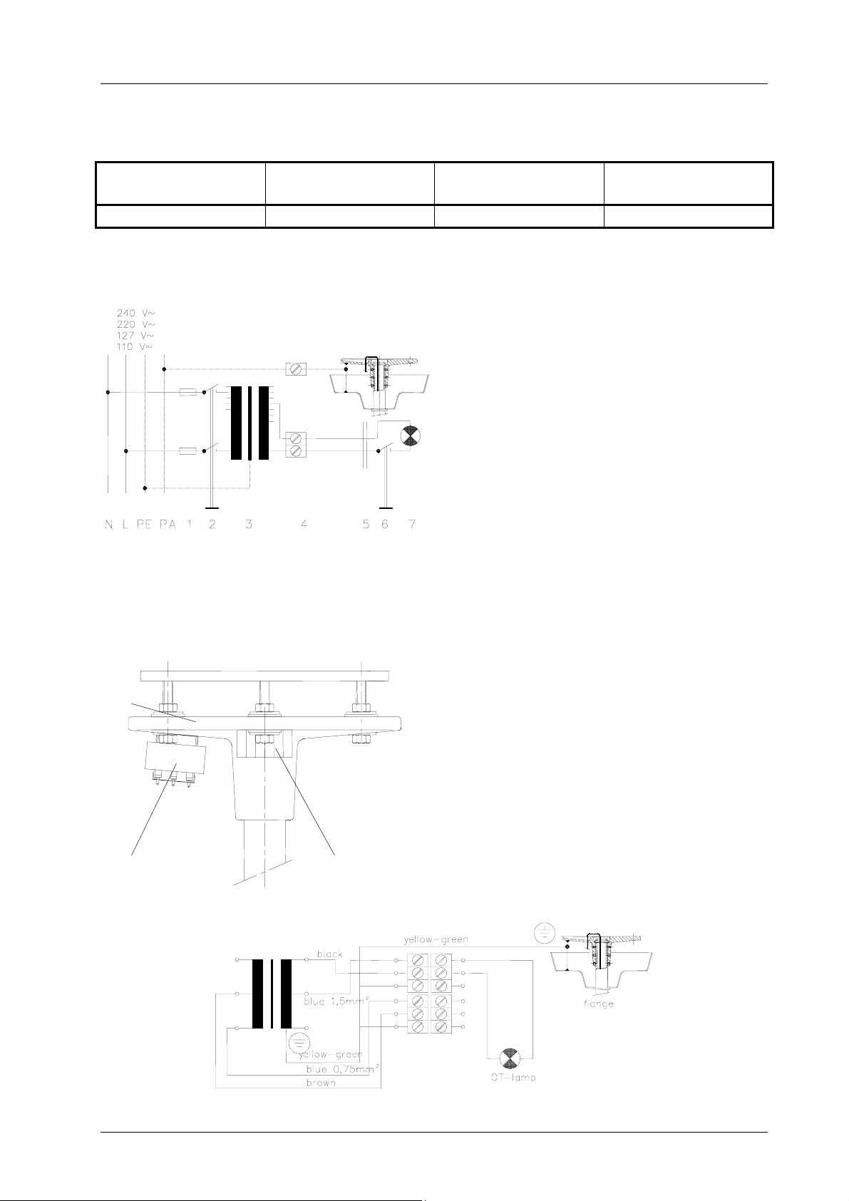
4.3 Wiring diagrams
External transformer (Mach 120 / Mach 130)
1. Fuses
2. ON/OFF switch (4-pole for emergency power
connection)
3. Transformer
4. Clamps on the flange
5. Coupling with sliding contact on lamp
6. Secondary ON/OFF switch
7. Light bulb
4.4 Ceiling lamps with external transformer
Single-phase transformer mounted on the flange
View
Flange
Transformer
Wiring
Line clamp
The single-phase transformer is already mounted
on the flange.
At delivery it is already connected to the line clamp.
You have to connect the power supply and the lamp
to the line clamp (see wiring).
59860005 Edition 03 24.10.2006 / Bak Page 11/20
Page 12
Ceiling attachment for Mach M2
5. Mounting the articulated arms and the lamp head
5.1 Mounting the articulated arms to the suspension tube
Suspension tube
1
2
5
4
Articulated arm
Dr. Mach
Lamps and Engineering
To mount the articulated arms proceed as follows:
• Loosen the screw 1.
• Remove cover 2 including the sliding contact-
plug.
• Remove circlip 3, gib washer 4 and levelling
washer 5 from the suspension tube (tool:
mounting plier).
• Slide the articulated arm onto the suspension
tube.
• Slide the levelling washer, gib washer and
circlip onto the suspension tube in the correct
order.
Take care to ensure that the nose of the gib
washer lies on the lateral bore (not shown) of
the suspension tube, and that the safety ring
slots properly into the groove of the suspension
pipe (tool: mounting plier).
• Place the cover 2 back on the articulated arm
and screw on with screw 1.
3
59860005 Edition 03 24.10.2006 / Bak Page 12/20
Page 13
Ceiling attachment for Mach M2
5.2 Mounting the lamp to the spring arm
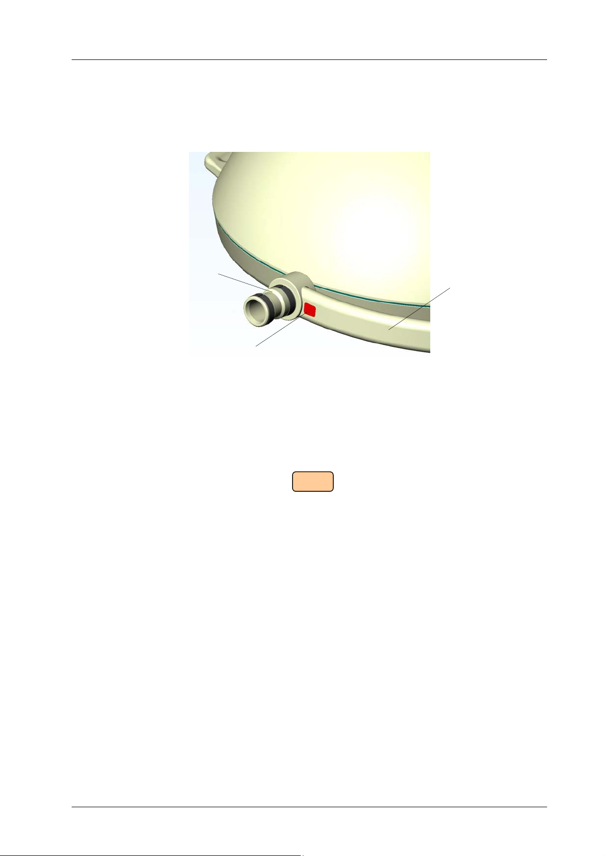
ATTENTION! Notice the rated voltage information!
Coupling journal
Dr. Mach
Lamps and Engineering
Lamp bow
Sticker with
voltage information
Each lamp has a red sticker applied near the coupling journal at the lamp bow. The sticker shows
the rated voltage of the lamp.
Connect the lamp only to the prescribed voltage, to avoid irreparable damage (e.g. the electrical
components).
Following rated voltage is usual:
22,8 V
After mounting the lamp take off the sticker and dispose it, otherwise it could fall down in the OTfield after some time!
59860005 Edition 03 24.10.2006 / Bak Page 13/20
Page 14
Ceiling attachment for Mach M2
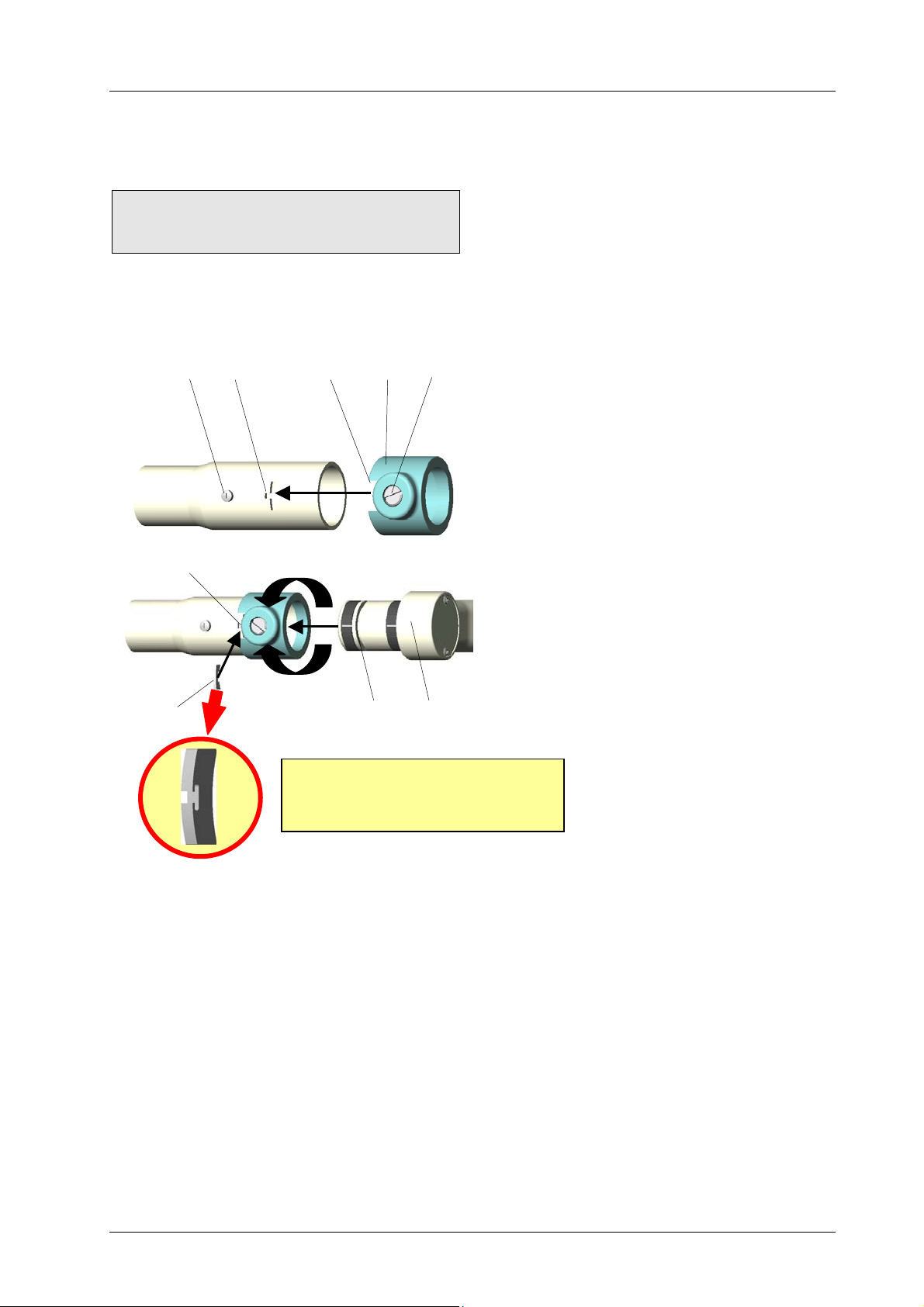
Do not remove screw 13, it is designed
to fix the sliding contact and provides
earthling!
5
13
3
3 3
180°
ATTENTION!
It is absolutely necessary to
mount this securing segment!
2
6 4
Dr. Mach
Lamps and Engineering
Attention: If the spring arm is pushed
downwards (the arm is under spring tension) it
may bounce up and cause harm. While
mounting the lamp head no other persons are
allowed to be within the swivel range of the
spring arm.
1
Mounting the lamp Mach M2 / M2F to the
spring arm
• Loosen brake screw 1, so the plastic bushing 2
can be slipped easy onto the spring arm.
• Slip plastic bushing 2 onto the spring arm to
overlap slots 3.
• Check if the journal 4 of the lamp is greased.
• Insert the greased journal 4 of the lamp and
insert security segment 5 completely into slot 3,
that the security segment leads in groove 6.
• Rotate plastic bushing 2 by 180° up to the
provided drilling for the brake screw and
screw in brake screw 1 until you reach the
desired brake effect for lamp head 4.
• Check if lamp head 4 is firmly fixed.
6. Cleaning
Note: Before doing any cleaning work turn off the lamp, disconnect from mains and make sure
that the lamp cannot be switched on again.
Please ensure, that no disinfection liquid flows into the joints or lamp head.
The surface of the ceiling attachment can be easily kept clean by simply wiping with a wet cloth. You can
use conventional cleaning agents.
Caution:
In order to prevent any damage at plastic parts, do not use scouring agents or alkaline, acidic and
alcoholic cleaning agents.
For cleaning proceed as follows:
• Draw plug from mains.
• Wipe the surface of the ceiling attachment with a wet cloth. As a cleaning agent you can use water or
a soap solution (washing-up liquid).
59860005 Edition 03 24.10.2006 / Bak Page 14/20
Page 15
Ceiling attachment for Mach M2
Dr. Mach
Lamps and Engineering
7. Maintenance
Note: Before doing any maintenance work, turn off the lamp, disconnect from mains and make
sure, that the lamp cannot be switched on again.
7.1 Periodical maintenance work
The following maintenance work / tests has / have to be done every six months:
• check on defects in paint work;
• check on fissures at plastic parts;
• check on deformation of the suspension.
The following maintenance work / tests has / have to be done once a year:
• check the function;
• electrical safety test;
• check the suspension.
Remark:
Check and grease the security segment once a year.
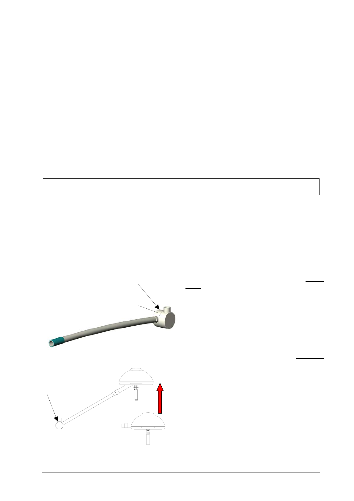
7.2 Adjusting the spring force
Springs are wearing parts, thus the spring force can decrease in time and must be readjusted.
Note: Set the spring force in such a way, that the spring arm with the lamp head holds its position
at every set height.
B
B
A
In case the spring arm with the lamp moves
down on its own, proceed as follows:
• Remove lateral cover A. The adjusting screw (B)
for the spring force is visible now.
• Push the lamp and spring arm upwards as much
as possible, so the spring is without charge.
• Insert a slotted screwdriver into the screw B.
• Turn the adjusting screw to the left
(anticlockwise), until the lamp holds its position
at every set height.
In case the spring arm with the lamp moves up
on its own, proceed as follows:
• Remove lateral cover A. The adjusting screw (B)
for the spring force is visible now.
• Push the lamp and spring arm upwards as much
as possible, so the spring is without charge.
• Insert a slotted screwdriver into the screw B.
• Turn the adjusting screw to the right
(clockwise), until the lamp holds its position at
every set height.
59860005 Edition 03 24.10.2006 / Bak Page 15/20
Page 16
Ceiling attachment for Mach M2
Dr. Mach
Lamps and Engineering
7.3 Maintenance of the segment
• Dismount the lamp head in reverse order of mounting (see chapter 5.2).
• Check the thickness of the segment. It must be at least 1,5mm. In case the thickness of the segment
is less than 1,5mm, it has to be changed.
• Grease the segment and the coupling journal of the lamp.
• Mount the lamp to the spring arm (see chapter 5.2).
8. Data
8.1 Technical data
Primary voltage 230V
Secondary voltage 22,8 V
Frequency 50 / 60Hz
Ceiling attachment
Power consumption 80W
Rated current at 24V 3,3A
Protection class I.
The device is not suitable for use in combustible blends of anaesthesia agents with air or for use in
combustible blends of anaesthesia agents with oxygen or nitrous oxide.
The device is designed for continuous operation.
8.2 Environmental conditions
Operation
Temperature +10°C +40°C
Relative atmospheric humidity 30% 75%
Air pressure 700hPa 1060hPa
Transport / storage
Temperature +10°C +40°C
Min. Max.
Min. Max.
Relative atmospheric humidity 30% 75%
Air pressure 700hPa 1060hPa
59860005 Edition 03 24.10.2006 / Bak Page 16/20
Page 17

Ceiling attachment for Mach M2
Dr. Mach
Lamps and Engineering
9. Disposal
The ceiling attachments do not contain any danger goods.
The components of the ceiling attachment should be properly disposed at the end of its shelf life. In order
to respect all regulations for disposal, please contact us before disposing the product.
10. CE- mark
The ceiling attachments comply to the standards 93/42/EEC for medical products of the
European Community’s Council. Dr. Mach applies the standard EN 60601-2-41.
Dr. Mach GmbH is certified according to DIN EN 46001:1996 and DIN EN ISO
13485:2001.
59860005 Edition 03 24.10.2006 / Bak Page 17/20
Page 18
Ceiling attachment for Mach M2
11. Dimensions and range of movement
Dr. Mach
Lamps and Engineering
59860005 Edition 03 24.10.2006 / Bak Page 18/20
Page 19
Ceiling attachment for Mach M2
12. Spare parts
Dr. Mach
Lamps and Engineering
2
37,38
39,42
30
1
4,5,6,7
8
10,11
12,13
14
17,18
15
16 (24)
3
36
31
23
21
20
26
27(28)
21
20
19
19
35
22
27(28)
33
Mach M2
27(28)
40,41
43,44
25
59860005 Edition 03 24.10.2006 / Bak Page 19/20
Page 20

Ceiling attachment for Mach M2
Dr. Mach
Lamps and Engineering
13. Spare parts list
Item Pcs. Name EDVNO Remarks
01 1 Ceiling anchoring ring TK 270 50480001
02 6 Safety dowels for ceiling anchoring ring 74011018
03 1 Ceiling flange TK 270mm 50482301
04 12(24) Nut M12 DIN 934-8 galZn 65332023 ( ) with int. flange
05 12 Washer 13 DIN 9021 galZn 65272001
06 12 Insulating washer 50281222
07 6(12) Blocking washer SK12 galZn ( ) with int. flange
08 1 Safety bolt 50753203
09
10 6 Hexagonal head screw M6x16 DIN 933
11 6 Retaining ring B6:A2 DIN 127
12 1 Canopy 50/450 50222203 optional
13 1 Canopy, divided 50/450 50222208 optional
14 1 Ring 50mm 50222202
15 1 Suspension tube 50x4 50221001-
50221028
16 1 Sliding contact socket (3-pole) 67330001 Not shown
17 6 Countersunk screw M6x16 DIN 7991 galZn 65162006
18 6 Cover, white
19 1 Circlip (Seegerring) 74011014
20 1 Gib washer 74011013
21 1 Levelling washer 74011012
22 1 Securing sleeve 74013012 Ondal 1502738
23 1 Connecting cable 680-2000mm 50224001-
50224028
24 1 Sliding contact complete 50223001-
50223028
25 1 Brake screw 74015007
26 2 Screw for cover M3x4 DI´N 966 65112029
27 2 Cover 74015022
28 2 Sliding contact for new-type swing Ondal T19694
29
30 1
31 1 Transformer 130VA 230V 67010202 At the flange
32
33 1 Spring arm 4-5 kg, complete 74861005
34
35 1 Securing segment 74015006
36 1 Cellular rubber seal, length 1430mm 50222209
37 1 Ring 50754201
38 1 Washer 50754202
39 1
40 1 Lateral cover, left 74015010 Ondal T37284
41 1 Lateral cover, right 74015011 Ondal T38505
42 2 Cover, white
43 1 Screw M3x10 D7985:Zn 65152045
44 1 Lock washer A3,2 65582003
Flange tube ∅ 70mm
Bolt ∅8x59
50751001-
50751008
50753202
Length 180mm to
1500mm
Pos. 16 + Pos. 23
complete
Length 300mm to
1000mm
50754001
59860005 Edition 03 24.10.2006 / Bak Page 20/20
 Loading...