

Page 1
PRIMECARE
®
*Shown with Optional Deluxe
Manual must be given to the Owner/User
of this bed and should be read carefully before
an accessible location for future reference.
P703 Long Term Care Bed
OWNER’s MANUAL
putting this product into use. Keep manual in
Rotating Assist Rails/Bars .
Page 2

Page 1
P703 Owner's Manual| REV 001
Dec 1
st
, 2017
TABLE OF CONTENTS
STANDARD SYMBOLS USED IN THIS MANUAL ............................................................................. 2
WARNING LABELS .......................................................................................................................... 3
INTENDED USE ................................................................................................................................ 4
CONTRA-INDICATIONS ................................................................................................................. 4
GENERAL SAFETY ........................................................................................................................... 4
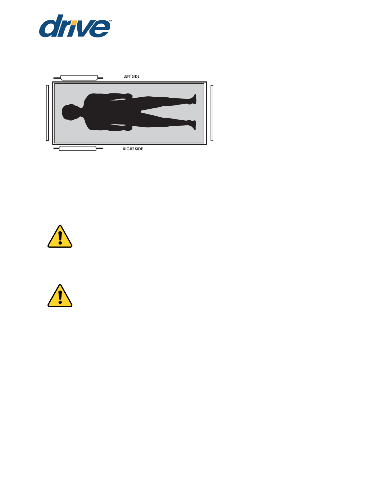
LEFT/RIGHT REFERENCE GRAPHIC ............................................................................................... 9
ELECTROMAGNETIC EMMISSION AND IMMUNITY ..................................................................... 9
FEATURES AND ACCESSORIES .................................................................................................... 13
TECHNICAL SPECIFICATIONS ..................................................................................................... 14
COMPLIANCE INFORMATION .................................................................................................... 15
UNPACKING INSTRUCTIONS ....................................................................................................... 16
ASSEMBLY ..................................................................................................................................... 17
ACCESSORY INSTALLATION ........................................................................................................ 21
BED OPERATION .......................................................................................................................... 40
BED MOBILIZATION AND STABILIZATION ................................................................................... 43
CARE AND MAINTENANCE ........................................................................................................ 44
INSPECTIONS ................................................................................................................................ 45
SERVICING ................................................................................................................................... 47
TROUBLESHOOTING GUIDE ........................................................................................................ 49
WARRANTY ................................................................................................................................... 50
END OF LIFE DISPOSAL ................................................................................................................ 52
APPENDIX ..................................................................................................................................... 52
NOTE: DO NOT operate this product without first reading and understanding this user
manual. Damage or injury may result from improper use of this product.
The information in this document is subject to change without notice.
Page 3

P703 Owner's Manual| REV 001
Page 2
Dec 1
st
, 2017
STANDARD SYMBOLS USED IN THIS MANUAL
This manual includes important information about the safety of personnel and
equipment. As you read through this manual be aware of the symbols and their
meanings.
DANGER
Information that appears under the DANGER symbol concerns the protection of
personnel from direct and pending hazards that, if not avoided, will result in immediate,
serious personal injury or death in addition to damage of the equipment.
DANGER SHOCK HAZARD
Information that appears under the DANGER SHOCK HAZARD symbol concerns the
protection of personnel from possible hazards related to electrical shock.
FIRE HAZARD
Information that appears under the FIRE HAZARD symbol concerns the protection of
personnel from possible hazards related to fire and flammability.
WARNING
Information that appears under the WARNING symbol concerns the protection of
personnel from possible hazards that can result in injury or death in addition to damage
of the equipment.
CAUTION
Information that appears under the CAUTION symbol concerns the protection of
personnel from possible hazards that may result in minor injury or damage of the
equipment.
CRUSH HAZARD
Information that appears under the CRUSH HAZARD symbol concerns the protection of
personnel from possible hazards related to reduce clearances.
NOTE:
Information that appears with the NOTE text gives added information, which helps in
understanding the item being described.
The information in this document is subject to change without notice.
Page 4
Page 3
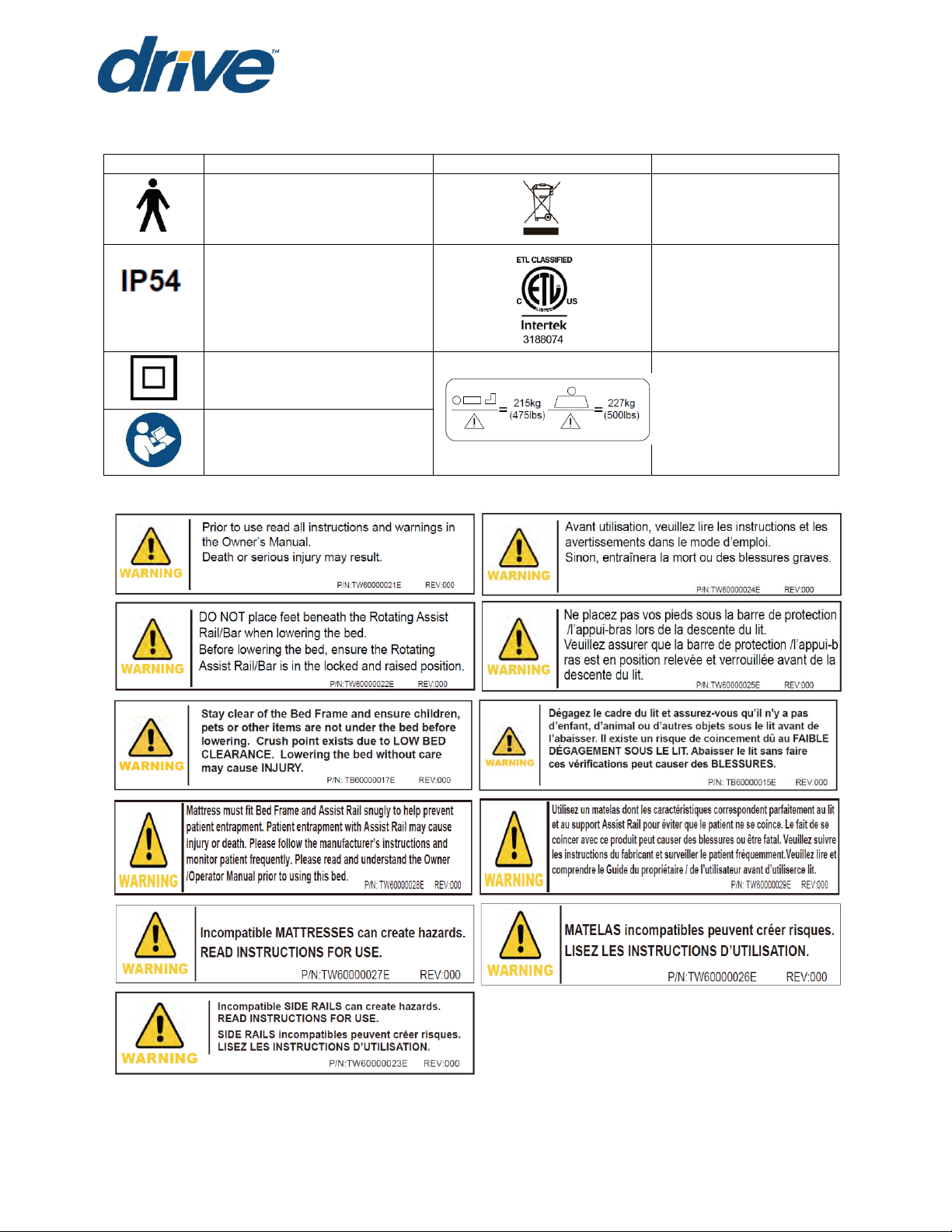
Symbols
Description
Symbols
Description
Type B applied part equipment
Recycle the item in
accordance with local
regulations.
According to IEC 60529. Rating for
dust-protection and identified as
equipment that is protected
against splashing water jets
Intertek’s ETL listed mark for
US and Canada. A product
bearing the ETL listed Mark is
determined to have met
the minimum requirements
of prescribed product
safety standards.
Class II equipment
Maximum patient weight
and safe working load.
The owner’s manual must be read
before operating the bed.
PRODUCT SYMBOLS
P703 Owner's Manual| REV 001
Dec 1
st
, 2017
WARNING LABELS
The information in this document is subject to change without notice.
Page 5

P703 Owner's Manual| REV 001
Page 4
WARNING
NEVER allow anyone under the bed at any time.
DO NOT let any body parts protrude over the side or between parts, especially
when the bed is being operated.
This bed should not be placed in an oxygen enriched environment.
Unplug bed or stop pressing pendant button when bed does not function as
expected.
DO NOT operate this product without first reading and understanding this user
manual. Damage or injury may result from improper use of this product.
Possible injury or Death may occur if accessories are not provided by Drive
DeVilbiss Healthcare. Please contact Drive DeVilbiss Healthcare for accessories
that are compatible with this bed.
Possible injury or Death may occur if replacement parts are not provided by
Drive DeVilbiss Healthcare. Please contact Drive DeVilbiss Healthcare for
replacement parts compatible with this bed.
Dec 1
st
, 2017
INTENDED USE
The PrimeCare P703 bed is intended for use within an institutional healthcare
environment, Application Environment 3 (i.e.: Skilled Nursing, Transitional Care,
Rehabilitation Care, Assisted Living).
Compliance with the regulations and guidelines as specified by your facility is
recommended.
This bed is NOT intended for patient/resident transport. Wheels are provided only to
allow movement within the patient/resident room for cleaning or patient/resident access.
CONTRA-INDICATIONS
This bed should not be operated (control the movements of the bed through the control
interfaces)by persons who do not have the cognitive skills to understand the information
in the owner’s manual or cannot understand and perform the proper operation of the
bed. This bed should not be used or operated by children.
GENERAL SAFETY
NOTE: In this manual, the terms patient and resident refer to a resident of a nursing home,
Long Term Care, assisted living or rehabilitation facility.
The information in this document is subject to change without notice.
Page 6

Page 5
WARNING
Power cord must be plugged into appropriate wall outlet, ensuring it can be
unplugged easily in case of an emergency.
Never permit more than one (1) person in/on the bed at any time. Never exceed
the weight capacity of this bed. The maximum safe working load for this bed
including resident/patient, bedding, support surface and accessories is 500lbs
(227kg), with weight evenly distributed and the maximum patient weight is 475
lbs (215kg). The weight of the accessories are show as below:
ACCESSORY DESCRIPTION
WEIGHT
Head/Foot Board
33 Ibs (15kg)
Mattress
21 Ibs (9.5kg)
Deluxe Rotating Assist Rail (pair)
24.2 Ibs (11kg)
Rotating 1/4 Assist Rail (pair)
18 Ibs (8.2kg)
Rotating Assist Bar (pair)
11.9 Ibs (5.4kg)
Width Extension
22 Ibs (10kg)
Trapeze
42.9 Ibs (19.5kg)
Staff Control Panel
0.8 lbs (0.36kg)
Battery Backup
3.4 lbs (1.6kg)
Length Extension 88"
6.8 lbs (3.1kg)
The medical bed should be left in its lowest position except when care is being
provided in order to reduce risk of injury due to falls.
The bed MUST be connected to an appropriate power source. Unless equipped
with the optional battery backup, this bed will not operate when not plugged in.
Mains cable and proper function must be checked regularly.
Possible Injury or Death may occur if bed is pushed over abrupt thresholds while
bed is occupied. This bed is not intended for patient/resident transport. Please
use an approved resident transport device when moving a resident.
P703 Owner's Manual| REV 001
Dec 1
st
, 2017
The information in this document is subject to change without notice.
Page 7

Page 6
DANGER SHOCK HAZARD
DO NOT plug anything into the control box of bed (i.e. pendants and actuators)
while mains cable (power cord) is plugged into the wall outlet.
Any cords or tubing used on or with this bed MUST be routed and secured
properly to ensure that they do NOT become entangled, kinked or severed
during normal operation of the bed.
DO NOT roll the bed over any power or pendant cords.
This bed is equipped with a three-prong grounding plug for protection against
possible shock hazard. DO NOT under any circumstances cut or remove the
grounding prong.
DO NOT open any actuators, control boxes, pendants or battery. Service and
repair must only to be performed by authorized service personnel. If
unauthorized service is performed on any components the warranty is void.
Inappropriate handling of power supply cords can create a shock hazard.
When routing cables from other equipment in the medical bed, precautions shall
be taken to avoid squeezing those between parts of the medical bed.
DO NOT allow the cord, electrical outlets, and electrical control box or hand
pendant to become wet or submerged.
DO NOT operate the bed if any electrical component such as the power cord,
electrical outlet, connections, motor/actuator or mechanical component has
malfunctioned or has been damaged in any way.
To avoid risk of electric shock, this equipment must only be connected to a
supply mains with protection earth.
The bed MUST be connected to an appropriate power source. Unless equipped
with the optional battery backup, this bed will not operate when not plugged in.
Mains cable and proper function must be checked regularly.
Possible injury or Death may occur due to pendant cord being a source for
entangling patient/resident. Patients/residents with decreased mental acuity
should NOT have access to pendant.
P703 Owner's Manual| REV 001
Dec 1
st
, 2017
The information in this document is subject to change without notice.
Page 8

Page 7
FIRE HAZARD
DO NOT use near open flame or explosive gases.
Possible Fire Hazard if used with nasal mask in 1/2 bed tent 0
2
administering
equipment. If 02 tent is being used it should not fall below the mattress deck. The
pendant should not be placed in an oxygen enriched environment such as an 02
tent.
This bed should not be placed in an oxygen enriched environment.
CAUTION
This medical bed is not intended to work with patient lifts other than those
specified by Drive DeVilbiss Healthcare as being compatible.
Do NOT use rotating assist bars/rails as handles for moving the bed.
Keep all moving parts, including the mattress deck (sleep surface), main frame,
all drive actuators and moving components free of obstructions.
Ensure that the individual using this bed is properly positioned, particularly when
the bed is being operated.
Body weight should be evenly distributed over the sleeping surface of the bed.
Avoid situations where entire body weight is on a raised head or foot surface.
This includes while assisting the resident in repositioning or transferring in or out of
bed.
Supervision is required when this product is operated by or near children or
people with disabilities.
Do not modify this bed without authorization of the manufacturer. If unauthorized
service is performed on any components the warranty is void.
This bed frame complies with EMC requirements of IEC 60601-1-2. Radio
transmitting equipment, cell phones or similar electronic devices, used in
proximity of the bed, may affect the beds performance.
P703 Owner's Manual| REV 001
Dec 1
st
, 2017
The information in this document is subject to change without notice.
Page 9

Page 8
CRUSH HAZARD
Possible crush hazard exists when pressing the Foot Lock Mechanism to the floor.
This feature was designed to be activated by your foot. Using your hand could
result in injury. Keep feet out from under Foot Lock Mechanism when activating.
Possible crush hazard exists between the floor and the square tubes used for
mounting rotating assist bars/rails. Keep feet out from under the square tubes on
the edge of the bed while operating the bed.
Possible Injury may occur when lowering or raising the bed. Keep feet and hands
clear of bed frame.
ENTRAPMENT WARNING
The entrapment issues can still arise when components and accessories are not
properly installed.
If a resident/patient’s mental or physical condition could lead to resident/patient
entrapment, the mattress deck (sleep surface) should be left in the flat position
when unattended. Failure to do so could result in injury or death.
Incompatible mattress and assist rails/bars can create hazards. Only compatible
Drive DeVilbiss Healthcare rotating assist bars and rails may be used on this bed.
Make sure mattress is the correct size for bed frame and the assist bars are
secured to frame to decrease the risk of entrapment.
If bed frames have been serviced or any other adjustments have been made,
you must ensure all parts are securely back in place before operating the bed.
MATTRESS SPECIFICATIONS WARNING
Possible ENTRAPMENT Hazard may occur if you do not use the recommended
specification mattress.
Resident entrapment may occur leading to injury or death.
A mattress may not be included with this bed. It is recommended that a 36", 39”,
or 42” wide mattress that is made to fit an 76”,80”, 84" or 88” length bed frame is
used, such as a Drive DeVilbiss Healthcare Pressure Redistribution Mattress.
Mattress height must be a minimum of 5-1/2 inches and a maximum of 7 inches.
Also available are Drive DeVilbiss Healthcare’s assortment of mattress overlays
and Low Air Loss flotation mattress systems.
See Technical Specifications page for compatible mattress dimensions.
P703 Owner's Manual| REV 001
Dec 1
st
, 2017
The information in this document is subject to change without notice.
Page 10
Page 9
P703 Owner's Manual| REV 001
Dec 1
st
, 2017
LEFT/RIGHT REFERENCE GRAPHIC
ELECTROMAGNETIC EMMISSION AND IMMUNITY
This MEDICAL ELECTRICAL EQUIPMENT needs special precautions regarding EMC and
needs to be installed and put into service according to the EMC information provided in
the table below.
Portable and mobile RF communications equipment can affect MEDICAL ELECTRICAL
EQUIPMENT
WARNING
The use of ACCESSORIES, transducers and cables other than those specified, with the
exception of transducers and cables sold by the manufacturer of the EQUIPMENT or
SYSTEM as replacement parts for internal components, may result in increased EMISSION
or decreased IMMUNITY of the EQUIPMENT or SYSTEM.
WARNING
The ME EQUIPMENT or SYSTEM should not be used adjacent to or stacked with other
equipment and that if adjacent or stacked use is necessary, the ME EQUIPMENT or
SYSTEM should be observed to verify normal operation in the configuration in which it will
be used.
The information in this document is subject to change without notice.
Page 11

Dec 1
Page 10
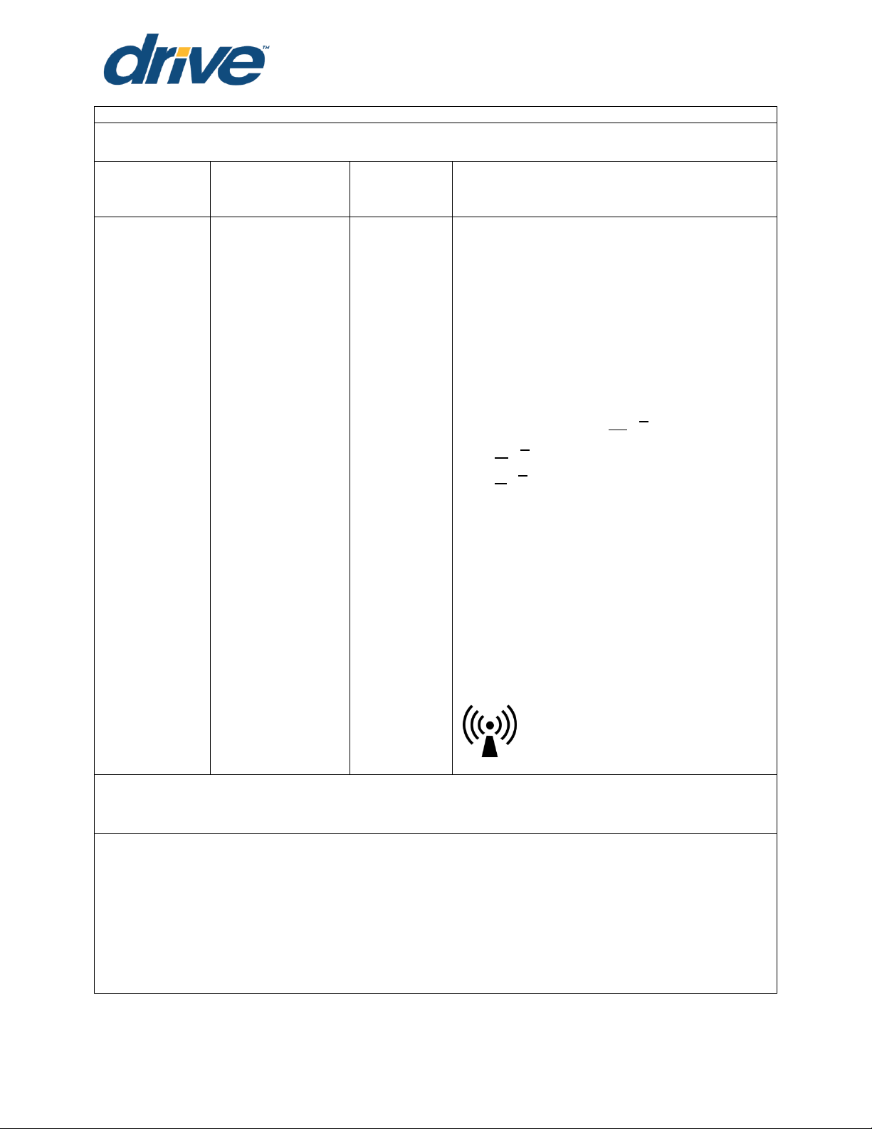
Guidance and manufacturer's declaration - Electromagnetic emissions
The Prime Care™P703 is intended for use in the electromagnetic environment specified below.
The customer or the user of the Prime Care™P703 should ensure that it is used in such an
environment.
Emissions Test
Compliance
Electromagnetic environment - Guidance
RF Emissions CISPR 11
Group 1
The Prime Care™P703 uses RF energy only for its
internal function. Therefore, its RF emissions are
very low and are not likely to cause any
interference in nearby electronic equipment.
RF Emissions
CISPR 11
Class B
Harmonic Emissions
IEC 61000-3-2
Class A
The Prime Care™P703 is suitable for use in all
establishments including domestic
establishments and those directly connected to
the public power supply network that supplies
buildings used for domestic purposes.
RF emissions
CISPR 14-1
Complies
The Prime Care™P703 is not suitable for
interconnection with other equipment.
RF emissions
CISPR 15
Complies
DECLARATION - ELECTROMAGNETIC EMISSIONS
P703 Owner's Manual| REV 001
st
, 2017
The information in this document is subject to change without notice.
Page 12

Page 11
Recommended separation distances between portable and mobile
RF communications equipment and the Prime Care™P703
The Prime Care™P703 is intended for use in the electromagnetic environment in which radiated RF disturbances are
controlled. The customer or the user of the Prime Care™P703 can help prevent electromagnetic interference by
maintaining a minimum distance between portable and mobile RF communications equipment (transmitters) and the
Prime Care™P703 as recommended below, according to the maximum output power of the communications
equipment.
Rated maximum output power
of transmitter
W
Separation distance according to frequency of transmitter
m
150 kHz to 80 MHz
80 MHz to 800 MHz
800 MHz to 2,5 GHz
0.01
0.12
0.12
0.23
0.1
0.38
0.38
0.73
1
1.2
1.2
2.3
0.1
0.38
0.38
0.73
10
3.8
3.8
7.3
100
12
12
23
For transmitters rated at a maximum output power not listed above, the recommended
separation distance d in meters (m) can be estimated using the equation applicable to the
frequency of the transmitter, where P is the maximum output power rating of the transmitter in
watts (W) accordable to the transmitter manufacturer.
NOTE: I At 80 MHz and 800 MHz the separation distance for the higher frequency range
applies
NOTE: 2 These guidelines may not apply in all situations. Electromagnetic propagation is
affected by absorption and reflection from structures, objects and people.
P703 Owner's Manual| REV 001
Dec 1
st
, 2017
The information in this document is subject to change without notice.
Page 13
Page 12
Guidance and manufacturer's declaration: Electromagnetic Immunity
The Prime Care™P703 is intended for use in the electromagnetic environment specified below. The customer or the user
of the Prime Care™P703 should ensure that it is used in such an environment.
Immunity test
IEC 60601 test
level
Compliance
level
Electromagnetic environment - guidance
Conducted
RF
IEC 61000-4-6
Radiated RF
IEC
61000-4-3
3 Vrms
150 kHz to 80 MHz
3 V/m
80 MHz to 2.5 GHz
10 V
10 V/m
Portable and mobile RF communications
equipment should be used no closer to any
part of the Prime Care™P703, including
cables, than the recommended separation
distance calculated from the equation
applicable to the frequency of the
transmitter.
Recommended separation distance
80MHz to 800MHz
800MHz to 2,5GHz
Where P is the maximum output power
rating of the transmitter in watts (W)
according to the Transmitter manufacturer
and d is the recommended separation
distance in meters (m). Field strengths from
fixed RF transmitters, as determined by an
electromagnetic site survey,
a
should be less
than the compliance level in each
frequency range.b
Interference may occur in the vicinity of
equipment marked with the following
symbol:
NOTE: I At 80MHz and 800MHz the higher frequency range applies.
NOTE: 2 These guidelines may not apply in all situations. Electromagnetic propagation is
affected by absorption and reflection from structures, objects and people.
a
Field strengths from fixed transmitters, such as base stations for radio (cellular/cordless)
telephones and land mobile radios, amateur radio, AM and FM radio broadcast and TV
broadcast cannot be predicted theoretically with accuracy. To assess the electromagnetic
environment due to fixed RF transmitters, an electromagnetic site survey should be considered. If
the measured field strength in the location in which the Prime Care™P703 is used exceeds the
applicable RF compliance level above, the Prime Care™ P703 should be observed to verify
normal operation. If abnormal performance is observed, additional measures may be
necessary, such as reorienting or relocating the Prime Care™ P703.
b
Over the frequency range 150 kHz to 80 MHz, field strengths should be less than 10 V/m.
P703 Owner's Manual| REV 001
Dec 1
st
, 2017
The information in this document is subject to change without notice.
Page 14
Page 13
FEATURES AND ACCESSORIES
Standard Features
76’’,80”, and 84” adjustable sleep surface
Height adjustable from 7” to 30”.
Synchronized control system.
Roll-at-any-Height design
Floor Lock System: Foot Pad Lock Mechanism
Welded Tubular Steel Frame
Slat Sleep Deck
Wall Guard
IV Pole Holders
Heavy Duty 3” Dual Footprint Casters
Adjustable Mattress Retainers
Heel Lift Ratchet
Soft Grey Frame
Under bed light
Accessories and Options
Pressure Reduction Mattress
Air Flotation Mattress
Cushion Fall Mat
Assorted Bed End styles & colors
39”-42” Integrated width extension
Staff Control Panel
Rotating Assist Rails &Bars
Deluxe Rotating Assist Rails
Battery Back-Up
Trapeze Assembly
Bed Transporter System
88" Length Extension
P703 Owner's Manual| REV 001
Dec 1
st
, 2017
WARNING
Incompatible mattress and rotating assist bars/rails can create hazards. Read
instructions for use.
Bed Serial Numbers
When ordering parts or when contacting Drive DeVilbiss Healthcare Customer Service
Department, please include bed's model and serial numbers, found on the identification
labels as below. The identification labels are located under the sleep deck on the either
side of the bed frame.
The information in this document is subject to change without notice.
Page 15
Page 14
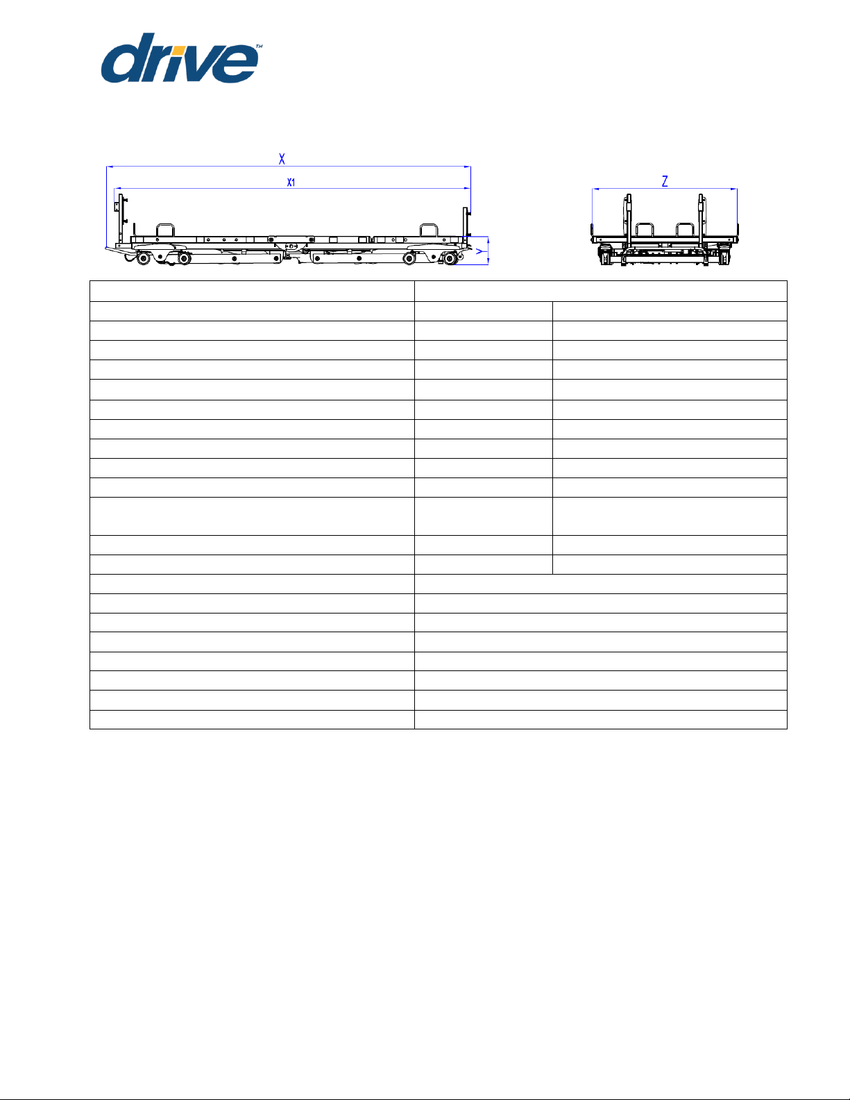
ITEM
SPECIFICATION
Overall Length (with wall bumper) (X)
89”,93”,97”,101”
227cm,237cm,247cm,257cm
Overall Length (without wall bumper) (X1)
83”,87”,91”,95”
212cm,220cm,230cm,240cm
Bed height range (Y)
7” to 30”
17.8cm to 76.2cm
Overall Width without width extension* (Z)
36”
91.4cm
Overall Width with width extension(Z)
39” or 42”
99cm” to 107cm
Length of Mattress Deck
76”
1934cm
Mattress Thickness Range
5.5" to 7"
14cm to 18cm
Mattress Lengths without length extension
76”, 80”, 84”,
193cm,203cm, 213cm
Mattress Lengths with length extension
88”
223.5cm
Mattress Width
36" , 39” ,42"
91.5cm,99cm, 107cm
Weight of Bed without H/F boards or
accessories
215.8 lbs
98.1kg
Maximum Weight Capacity (SWL)**
500 lbs
227 kg
Maximum User’s Weight
475 lbs
215kg
Head Deck Angle Range
0° to 65°
Thigh Deck Angle Range
0° to 32°
Foot Deck Angle Range
0° to 11°
Input Voltage***
100-240 VAC, 50/60 Hz
Protective Earth Ground
CLASS II
Electrical Shock Protection
TYPE B
Enclosure Protection
IP54
Duty cycle
Min. 2min (on)/ Max. 18min (off)
TECHNICAL SPECIFICATIONS
P703 Owner's Manual| REV 001
Dec 1
st
, 2017
NOTE: All length and height measurements ± .75”, Angle measurements ± 3°
* Rotating Assist Bar/Rails add 3” (7.5cm) to each side of the bed
**SWL includes the weight of the resident/patient and all other accessories including, but
not limited to mattresses, head/footboards, rotating assist bars, etc.
***Means of isolating equipment from supply mains:
This bed may be isolated from the supply mains by unplugging the mains cable (power
cord) from the wall outlet.
The information in this document is subject to change without notice.
Page 16

Page 15
Operation
Storage/Transportation
Ambient temperature:
10°C ~ 36°C (50°F~96.8°F)
-10°C ~ 50°C (14°F~122°F)
Relative humidity range:
30% ~ 75%
20% ~ 95%
Atmospheric pressure:
86KPa~ 106Kpa
70KPa~ 106KPa
P703 Owner's Manual| REV 001
Dec 1
st
, 2017
COMPLIANCE INFORMATION
Matching the correct bed components to meet regulatory specifications can be
complicated. Drive DeVilbiss Healthcare offers a wide variety of compliance options and
we can assist your facility in selecting components or accessories that are
recommended for the specific bed model.
General information
The recommended environment for operation and storage/transportation of the bed is
listed below:
This bed is classified for intermittent operation. Bed may be operated for 2 minutes out of
every 20 minutes.
Applied Parts List
Bed Frame
Head/ Foot Board
Rotating Assist Bars/ Rails
Mattress Retainer
Width Extension
Pendant
Trapeze
Staff control panel
Length Extension
Materials accessible to user
Surface Coating: Powder Coating
Color of Powder: Carbon black, Ethylene Bis-Stearamide, Solvent Red
Pendant Housing: ABS
Staff control panel housing: ABS
Plastic Cover of Rail/Bar: PU
Head/Foot Board: Wood
Trapeze: Nylon webbing
The information in this document is subject to change without notice.
Page 17

P703 Owner's Manual| REV 001
Page 16
Pliers or Wire Cutters
Utility Knife
Dec 1
st
, 2017
UNPACKING INSTRUCTIONS
TOOLS REQUIRED
CAUTION
Unpack the bed in an area with sufficient room to work. Do not allow residents/patients
near the bed until it has been completely set up and the work area has been cleared of
all debris.
1. Inspect the bed for shipping damage. If the bed is damaged. Do not use bed
and immediately contact Drive DeVilbiss Healthcare for further instruction.
2. Verify the proper bed model was shipped. If you feel there was a mistake. Do not
use bed and immediately contact Drive DeVilbiss Healthcare for further instruction.
3. After verifying you’ve received the correct device without damage, cut black
strapping around box and remove enclosing bed frame.
NOTE: If the carton is in an upright position, slowly lower to the floor. It may be
necessary for two or more people to help in lowering the bed.
4. Cut zip ties to remove wall guard at the head of the bed.
5. Cut the zip ties to remove mattress retainers on each side of the bed.
6. Remove ties from pendant.
7. Remove any remaining zip ties or foam left on bed frame.
NOTE: Damage to the equipment may occur if the zip ties are removed incorrectly.
CAUTION
DO NOT remove zip ties that are holding cords underneath bed frame.
INITIAL INSPECTION
1. Inspection of All Components - Receipt of assembled bed.
2. Check bed components for obvious damage.
3. Inspect power supply cords for cuts and/or damage.
4. Check that actuator cords are connected properly to the controller.
5. Locate power cord and plug into grounded 100-240VAC outlet.
6. Raise the bed frame and check to make sure everything is plugged into the
control box and no wires are loose. If wires are not in control box. Do not use bed
and immediately contact Drive DeVilbiss Healthcare for further instruction.
The information in this document is subject to change without notice.
Page 18

Page 17
Ability to read and understand
owner’s manual
Ability to manipulate required tools
Basic mechanical aptitude
1/4”Allen Wrench
5/16” Allen Wrench
DANGER
Possible injury or death may occur if the bed is not adjusted to the proper length for the
mattress being used.
Headboard support assemblies positions
76” Position
80” Position
Footboard support assemblies positions
76” Position
80” Position
84” Position
88” Position
(see note)
P703 Owner's Manual| REV 001
Dec 1
ASSEMBLY
KNOWLEDGE/SKILLS REQUIRED
HEADBOARD AND FOOTBOARD INSTALLATION AND ADJUSTMENT
TOOLS REQUIRED
1. Insert headboard or footboard support assembly, whichever is appropriate for the
end of the bed you are working on.
st
, 2017
2. There are mounting positions for 4 different mattress lengths, 76”, 80” ,84” and 88”.
Choose the one appropriate for your mattress.
The information in this document is subject to change without notice.
Page 19

P703 Owner's Manual| REV 001
Page 18
Headboard mounting tubes
Footboard mounting tubes
Dec 1
NOTE: 88” Position mentioned above is only used when the 88” length extension is
used (not shown here), please see the detail at Page 23.
3. Thread the 5/16” bolt into both sides of the bed frame and tighten to hold the
headboard/footboard support assemblies in place.
4. Mount the headboard/ footboard mounting tubes to the headboard/footboard
using 1/4” head/footboard mounting bolts.
st
, 2017
5. Slide the mounting tubes into the mounting brackets until they stop.
NOTE: The mounting tubes on the headboard face away from the bed. The
mounting tubes on the footboard face toward the inside of the bed.
6. Close the cam lock to secure the headboard/footboard in the mounting brackets
The information in this document is subject to change without notice.
Page 20

Page 19
Length Mattress Retainer
Width Mattress
Retainer
Used on head end
of the bed for 76”
and 80”/ 84”/88”
position
Used on foot end
of the bed for 76”,
80” and 84”
position
Used on foot end
of the bed for 88”
position
76” length position
80”/ 84 ” /88”
length Position
36” Width Position
39” Width Position
42” Width Position
76” length Position
80” length Position
84” length Position
88” length Position
P703 Owner's Manual| REV 001
Dec 1
MATTRESS RETAINER ADJUSTMENT
Mattress retainers are designed to keep the mattress in place on the sleep surface.
1. Determine the length and width of mattress.
2. Place correct length mattress retainer in the correct spot on head end of the bed.
st
, 2017
3. Place correct Length mattress retainer in the correct spot on foot end of bed.
4. Place your width mattress retainer in the correct spot.
The information in this document is subject to change without notice.
Page 21

P703 Owner's Manual| REV 001
Page 20
76” Length Position
80/84” Length Position
88” Length Position
Dec 1
5. Place mattress on mattress support deck. The mattress should be snug against all
of the mattress retainers.
NOTE: 88” Position mentioned above is only used when the 88” length extension is
used, please see the detail at Page 23.
NOTE: Make sure mattress fills length and width between mattress retainer stops. Also,
make sure the mattress does not compress more than 1.5” under patient/resident
weight.
WALL BUMPER INSTALLATION/ADJUSTMENT
The wall bumper is designed to prevent damage to facility walls by keeping the head
end of the bed spaced off the wall.
1. Slide the wall bumper over the axle at the head end of the bed.
st
, 2017
2. Insert the locking pin in the hole appropriate for the length of mattress you are
using.
The information in this document is subject to change without notice.
Page 22

Page 21
P703 Owner's Manual| REV 001
Dec 1
st
, 2017
PENDANT LOCATION
DANGER SHOCK HAZARD
Prior to working with any electrical parts, such as when plugging in the hand pendant,
make sure power to the bed frame is disconnected by removing mains cable from wall
outlet.
1. Plug the pendant into the end of the Y-cable located on the side of the bed you
want the pendant to be attached. This requires proper alignment of the pendant
cable and the y-cable.
2. Plug the pendant into the port of Y-cabel. Sercure the pendant by pressing the
locking clip.
3. Plug mains cable back into the wall outlet. Test all functions
WARNING
When routing cables in the medical bed, precautions shall be taken to avoid squeezing
between parts of the medical bed.
The information in this document is subject to change without notice.
Page 23

P703 Owner's Manual| REV 001
Page 22
Dec 1
ACCESSORY INSTALLATION
LENGTH EXTENSION (Option)
Note: Length Extensions only be used on foot end of the bed. This will expand the bed
from 76” to 88”.
1. Remove the length extension assemblies from their packaging, unscrew knobs
and take down the length mattress retainer.
2. Place the length extension over the bed frame at the foot end of the bed, align
the holes, insert a 3/8” bolt into the hole and tighten the bolt by the knob.
st
, 2017
3. Install the footboard assembly per “ HEADBOARD AND FOOTBOARD INSTALLATION
AND ADJUSTMENT” on page 17 of this manual
4. Place the mattress retainer at the 88” length position on length extension.
The information in this document is subject to change without notice.
Page 24

Page 23
Head section
Leg section
Foot section
P703 Owner's Manual| REV 001
Dec 1
st
, 2017
WIDTH EXTENSION (Option)
Note: Both sides of the Width Extensions must be used. This will expand the bed from 36”
to 39” and 42”.
1. Remove the width extension assemblies from their packaging.
2. There are three sections to each side of the Width Extension
3. Push the expansion button and insert the three sections into each side of the bed
deck.
4. Choose which width the bed needs to be expanded to. This bed has 2 width
settings: 39” and 42”.
5. Push the expansion button in and pull out width extension until you reach the
desired width of the bed deck.
6. Insert the locking pins into the bed frame to secure the width extensions.
NOTE: This bed can accommodate 36”, 39” and 42” width mattress, the appropriate
mattress MUST be used.
The information in this document is subject to change without notice.
Page 25

P703 Owner's Manual| REV 001
Page 24
5/16” Allen wrench
3/8” Allen wrench
9/16” wrench or socket
Utility Knife
Dec 1
TRAPEZE (option)
TOOLS REQUIRED
Note: Trapeze ONLY can be installed at the head of the bed.
1. Remove any items on the bed such as residents, mattresses and/or sheets.
2. Raise the mattress support platform to a comfortable working height.
3. Unplug the bed from mains power.
4. Move bed to a position in the room that allows a person to walk around the bed.
5. If the headboard and/or headboard mounting bracket is/are installed
Remove the headboard
Remove the 5/16” bolts from each side of the frame securing the headboard
mounting bracket and remove the headboard mounting bracket
st
, 2017
6. Unpack the package of the trapeze. Check the hardware and components.
The information in this document is subject to change without notice.
Page 26

Page 25
P703 Owner's Manual| REV 001
Dec 1
7. Insert the trapeze mounting bracket into the headboard end of the bed frame.
8. The label on the side of the trapeze mounting bracket will help align the holes in
the trapeze mounting bracket with the holes in the frame for the desired mattress
length. The line next to each position marking should line up with the end of the
mainframe tube. Position 1 = 76” mattress, Position 2 = 80”/84”/88” mattress .Two
holes one each side (4 total) are used for each mattress position. All holes must
line up for proper assembly.
st
, 2017
9. Secure the trapeze mounting bracket with four 5/16” bolts (2 per side).
10. Making sure you have clearance to not hit the ceiling, place the trapeze mast
onto the trapeze support bracket. Secure trapeze mast with twelve 3/8” bolts and
washers.
11. Plug the bed into mains power. Lower the bed to its lowest position, ensuring there
are no trapeze parts or other items under the bed.
The information in this document is subject to change without notice.
Page 27

P703 Owner's Manual| REV 001
Page 26
76” Length Position
80/84” Length Position
88” Length Position
Dec 1
12. Attach the trapeze boom assembly to the trapeze mast and secure with four 3/8”
bolts, eight 3/8” washers and four 3/8” nuts.
13. Raise and lower the bed to verify the trapeze will not hit the ceiling when the bed
is raised to its highest position.
14. Insert the headboard into the trapeze mounting bracket and secure headboard
by pressing down on cam lock handles.
st
, 2017
15. Adjust the wall bumper to the appropriate position to accommodate the trapeze.
16. Move the bed to its desired location. Raise and lower the bed to insure that the
wall bumper position chosen provides wall clearance.
The information in this document is subject to change without notice.
Page 28

Page 27
P703 Owner's Manual| REV 001
Dec 1
st
, 2017
ROTATING ASSIST RAIL/BAR INSTALLATION (Option)
ASSIST RAIL/BAR WARNING
Other manufacturers assist rails/bars may not be compatible and can lead to
entrapment issues or harm to patients/residents. Only compatible assist rails/bars may
be used on this bed. Make sure bed frame is adjusted correctly for mattress size being
used and assist rails/bars are properly secured to frame to decrease the risk of
entrapment.
ENTRAPMENT WARNING
The risks associated with these devices used in conjunction with specialty mattresses and
mattress overlays have not been evaluated. When these specialty mattresses or
mattress overlays are used, the end user facility must take steps to ensure that the
therapeutic benefit outweighs the risk of entrapment.
ASSIST RAIL/BAR WARNING
Assist rails/bars are intended only to assist the resident during bed entry and exit. These
devices are not side rails nor are they intended to be used in a manner that makes user
entry or exit more difficult.
CAUTION
The bed may become UNSTABLE due to interference between the rotation assist bar/rail
and the floor when lowering the bed. An unstable bed may tilt and /or cause possible
damage or personal injury.
CRUSH HAZARD
Crush hazard exists between the assist rails/bars and the floor when in the lowest position
which may cause injury to oneself or others. Do NOT place feet beneath the assist
rails/bars.
WARNING
When routing cables from other equipment in the medical bed, precautions shall be
taken to avoid squeezing between parts of the medical bed.
The information in this document is subject to change without notice.
Page 29

P703 Owner's Manual| REV 001
Page 28
Dec 1
st
, 2017
ENTRAPMENT WARNING
Accurate assessment of the resident and monitoring of correct maintenance and
equipment use are required to prevent entrapment. For additional information on
product and safety issues for bed frames and rails refer to product manuals specific to
the product or accessories you have or are planning to install. If bed frames have been
serviced or any other adjustments have been made, you must ensure all parts are
securely back in place before operating the bed. Other manufacturers assist rails may
not be compatible and can lead to entrapment issues or harm to residents and staff.
Make sure mattress is the correct size for bed frame and the assist rails are secured to
frame to decrease the risk of entrapment.
On March 10, 2006, the U.S. Food and Drug Administration (FDA) released guidelines for
reducing the risk of hospital bed entrapment entitled; “Hospital bed System Dimensional
and Assessment Guidance to Reduce Entrapment”. This guidance document identifies
potential entrapment areas within the bed frame, rails and mattress and identifies those
body parts most at risk for entrapment. It also provides manufacturers with basic design
criteria to consider when developing hospital/convalescent beds; recommends specific
test methods to assess the conformance of existing hospital/convalescent bed systems;
and answers frequently-asked questions about entrapment issues.
The FDA Guidance document identifies specific dimensional criteria on potentially injurythreatening gaps and spaces that can occur between bed system components, such as
side rails when improperly installed. Drive DeVilbiss Healthcare’s Long Term Care beds
and approved accessories are manufactured to be in conformance with these
guidelines.
Please be aware that entrapment issues can still arise when components and
accessories are not properly installed on the bed. It is important for the provider or
facility staff to recognize they have an equal role in complying with the FDA guidelines to
help ensure resident safety and avoid injuries.
Copies of this document can be obtained from the FDA website:
http://www.fda.gov/medicaldevices/deviceregulationandguidance/guidancedocume
nts/ucm072662.htm
The information in this document is subject to change without notice.
Page 30

Page 29
Option1:Mounting at the head deck only
Option2:Conjunction with the rotating
assist bar
Figure 1: Bars/ Rails Location
P703 Owner's Manual| REV 001
Dec 1
st
, 2017
MOUNTING LOACATION FOR ROTATING ASSIST RAILS/BARS
CAUTION
Rotating assist rails/bars must be mounted in the specified positions and orientations
shown in this owner’s manual. Failure to comply with these instructions will cause serious
injury.
DELUXE ROTATING ASSIST RAIL LOCATION:
Note: The deluxe rotation assist rail only can be mounted at the head deck ,
The information in this document is subject to change without notice.
Page 31

P703 Owner's Manual| REV 001
Page 30
Option1:Mounting at the head deck only
Option2:Conjunction with the rotating
assist bar
Dec 1
ROTATING 1/4 ASSIST RAIL LOCATION:
Note: The rotating 1/4 assist rail only can be mounted at the head deck
st
, 2017
ROTATING ASSIST BAR LOCATION
Note: The rotating assist bar only can be mounted at the foot deck, it cannot be used
separately, it should be used together with the assist rail as mentioned above.
The information in this document is subject to change without notice.
Page 32

Page 31
P703 Owner's Manual| REV 001
Dec 1
DELUXE ROTATING ASSIST RAIL INSTALLATION
1. Choose appropriate location holes for mounting. The mounting location is shown
in the Figure 1 above.
2. There are two washers on the bracket, take out one of the two washers.
3. Insert the mounting bracket of deluxe rotating assist rail into the location holes.
st
, 2017
4. Place the washer back to the mounting bracket, secure the rail by inserting the
bowtie clips into the mounting bracket.
5. If you want to push down or raise the rail,press the pin to push down
The information in this document is subject to change without notice.
Page 33

P703 Owner's Manual| REV 001
Page 32
Dec 1
st
, 2017
ROTATING 1/4 ASSIST RAIL INSTALLATION
WARNING
When rotating 1/4 assist rails are unlocked they are free to rotate. Care must be taken to
ensure the rotating 1/4 assist rail does not rotate toward the floor in an uncontrolled
manner.
1. Chose appropriate location holes for mounting. The mounting location is shown in
the Figure 1 above.
2. Insert the mounting bracket of rotating 1/4 assist rail into the location holes.
3. Secure the rotating 1/4 assist rail by inserting the locking pin into the bed frame.
4. If you want to push down or raise the rail , press the pin to push down or raise
The information in this document is subject to change without notice.
Page 34

Page 33
P703 Owner's Manual| REV 001
Dec 1
ROTATING ASSIST BAR INSTALLATION
WARNING
When rotating assist bars are unlocked they are free to rotate. Care must be taken to
ensure the rotating assist bars does not rotate toward the floor in an uncontrolled
manner.
1. Chose appropriate location holes for mounting. The mounting location is shown in
the Figure 1 above.
2. Insert the mounting bracket of rotating assist bar into the location holes.
3. Secure the rotating assist bar by inserting the locking pin into the bed frame.
st
, 2017
4. If you want to push down or raise the rail , press the pin to push down or raise
The information in this document is subject to change without notice.
Page 35

P703 Owner's Manual| REV 001
Page 34
Pliers or Wire Cutters
Philips Screwdriver
Routing Layout
Dec 1
STAFF CONTROL PANEL INSTALLTION AND ROUTING (OPTION)
TOOLS REQUIRED
1. Raise the bed to the highest position. Unplug power cord from wall outlet
2. Place the staff control panel in the foot board, screw bolts to fix the panel
3. Lift the foot deck to the highest position.
4. Route the cable along with the bed frame. Let the cable throughout the space
between bed frame and seat deck. See the routing layout as below.
st
, 2017
The information in this document is subject to change without notice.
Page 36

Page 35
P703 Owner's Manual| REV 001
Dec 1
5. Secure the cable on the bolts with zip ties .
6. Lift the head deck to the highest position. Remove the end cover by using
screwdriver.
7. Insert the plug into the port CH6 or CH7
st
, 2017
8. Insert the end cover in place.
9. Trim loose end of zip ties ensuring there is no sharp.
10. Lower the bed to the lowest position ensuring the moving parts will not pinch or
shear the cable.
The information in this document is subject to change without notice.
Page 37

P703 Owner's Manual| REV 001
Page 36
Philips screwdriver
3/8” Wrench or socket
Adjustable wrench
Dec 1
BATTERY BACK-UP (option)
TOOLS REQUIRED
NOTE: Battery backup is for EMERGENCY purposes ONLY
1. Mount the battery to the steel battery plate using the four #8 screws and nuts
included.
2. Install the battery plate to the center of the bed frame using three 3/8” screws
and washers included.
st
, 2017
3. Route the cable along with the bed frame , See the routing layout as below.
The information in this document is subject to change without notice.
Page 38

Page 37
Dec 1
4. Secure the cable on the bolts with zip ties .
P703 Owner's Manual| REV 001
st
, 2017
5. Remove the end cover by using screwdriver.
6. Insert the plug into the port CH5, Insert the end cover in place.
7. Trim loose end of zip ties ensuring there is no sharp.
8. The battery back-up will now work if the bed becomes unplugged from the wall
outlet or there is a power failure.
The information in this document is subject to change without notice.
Page 39

Page 38
NOTE:
Allow the battery to charge for a minimum of 24 hours before first use
Battery back-up is specified as a part of bed
Battery is not to be used in a damp environment such as outdoors
WARNING
The battery backup should be used for EMERGENCY PURPOSES ONLY. The only
compatible battery backup is the Timotion TBB2 battery.
DO NOT use the battery backup to demonstrate or display a bed.
If the battery backup is used, it MUST be recharged before becoming drained
and dormant. If the battery is run dead and left for any extended period of time,
the battery can go into HIBERNATION and cannot recover or be recharged.
Battery function should be checked periodically to insure battery health. The
battery should be removed, if leakage from battery.
Drive DeVilbiss Healthcare cannot be held responsible for improper backup use.
When a battery is connected to the control box, unplugging the bed from mains
power will not switch bed off.
The battery must be replaced by authorized service personnel ONLY.
CAUTION
If improperly performed, equipment or property DAMAGE or resident INJURY is
possible during maintenance.
The battery is not a toy for children to play with.
BATTERY BACK-UP INFORMATION
P703 Owner's Manual| REV 001
Dec 1
st
, 2017
Maintenance Notes:
Following longer periods of storage, the battery may need to be charged and
discharged several times so that performance reaches a peak.
Batteries will lose their charge during storage. Battery should be fully charged
prior to storing. A battery in storage should be recharged every 2 months at a
minimum.
Care tips
Make sure the battery is kept clean and dry at all times.
The battery must receive sufficient ventilation when charging or discharging.
Remove backup battery when bed is not likely to be used for some time.
The information in this document is subject to change without notice.
Page 40

Page 39
P703 Owner's Manual| REV 001
Dec 1
Safety tips
Don’t open or damage the battery.
Don’t expose the battery to heat or open flames. Avoid storing it in direct sunlight.
If the battery leaks and you come into contact with the fluid, wash the affected
area thoroughly in water and consult a doctor immediately.
Don’t throw the battery into fire, open it, solder or weld to it.
Cleaning Notes
Before cleaning, always unplug mains cable from wall outlet.
When cleaning, take care not to damage the connection cable.
Clean plastic surfaces such as the housing with slightly damp cloth. Never use
cleaning agents on battery.
Never use a high-pressure cleaner on the battery or spray fluids directly onto them
using jets. You risk damaging the equipment.
Solvents, alcohol, bleach, caustic agents, high acid or alkaline solutions or
petroleum based products should not be used on the bed.
NOTE: This bed NOT compatible with wash down tunnels.
st
, 2017
WARNING
Batteries must be disposed of in accordance with local regulations.
The information in this document is subject to change without notice.
Page 41

P703 Owner's Manual| REV 001
Page 40
WARNING
It is critically important to lock all casters and brake system to prevent
unintended bed movement.
Possible injury or Death may occur due to pendant cord being a source for
entangling patient/resident. Patients/residents with decreased mental acuity
should NOT have access to pendant.
1
2
3
4
1st button set controls raising and lowering of the head
frame.
Dec 1
st
, 2017
BED OPERATION
CRUSH HAZARD
Crush point exists due to LOW BED CLEARANCE. Do NOT place feet or other limbs under
the frame when lowering the bed. When lowering the bed, be aware this may cause
INJURY if limbs or personal items interfere with bed movement. Stay clear of the frame
and ensure children and/or pets are not under the bed before lowering the bed.
Initial Start Up (Bed Synchronization)
After position bed, always lock all casters and brake system. Bed should be
allowed to reach room temperature before plugging power cord into outlet.
Lower the bed to near the lowest position.
Hold the “Down” button until the bed reaches the lowest position and the LED
flashes 3 times on the pendant.
The bed is now synchronized. Operate bed as normal.
PENDANT OPERATION
The PrimeCare P703 bed comes standard with pendant control. Resident/patient
and staff can use the pendant to adjust all mattress support platform sections to
desired positions.
deck
2rd button set controls raising and lowering of the
thigh/foot deck.
3th button set controls raising and lowering of the head
and thigh/foot deck simultaneously.(Auto Contour)
4nd button set controls raising and lowering of the bed
NOTE: For every 2 minutes of continuous actuator use, the bed actuators must not be
used for 18 minutes.
The information in this document is subject to change without notice.
Page 42

Page 41
CAUTION
The use of Trendelenburg and Reverse Trendelenburg functions may not be
suitable for certain patients/residents. This function should only be used with the
recommendation and supervision of medical personnel.
To avoid damage to the wall, the head end of the bed should be moved away
from the wall when using the Trendelenburg function.
1 2 3 4 5
P703 Owner's Manual| REV 001
Dec 1
st
, 2017
5 Function Staff Control Pad Operation (optional)
st
1
button set controls raising and lowering of the
head deck
o While in locked position, this feature will not
work.
nd
2
button set controls raising and lowering of the
thigh/foot deck.
o While in locked position, this feature will not
work.
rd
3
button set controls raising and lowering of the head and thigh/foot deck
simultaneously. (Auto Contour)
o The auto-contour function will not work if either the head or foot motions are
locked.
th
4
button set controls raising and lowering of bed frame.
o While in locked position, this feature will not work.
th
5
button set controls Trendelenburg and Reverse Trendelenburg positions.
o While hi-lo movement is locked, these features will not work.
o While hi-lo movement is unlocked, these features will work.
o Pressing the bed frame up or down button may be required to get the bed to
move to a level position.
NOTE: For every two minutes of continuous actuator use, the bed actuators must not be
used for 18 minutes.
CRUSH HAZARD
To eliminate any potential crush hazard, the Trendelenburg and Reverse
Trendelenburg functions should be used only when the bed is at or near its highest
position. This bed is capable of an angle greater than 12° for Trendelenburg and
Reverse Trendelenburg positions. A crush hazard exists at the ends of the bed if
the bed angle is the maximum it can reach. DO NOT allow bed to go to an angle
greater than 14°.
The information in this document is subject to change without notice.
Page 43

P703 Owner's Manual| REV 001
Page 42
Dec 1
HEEL LIFT RATCHET ADJUSTMENT
1. With the thigh deck section set at the preferred position, lift the foot deck.
2. The manual foot lift section must be raised slowly to properly engage each stop at
the desired height. The foot lift section will not lower past the nearest engaged
stop.
3. To reset the ratchet mechanism and lower the manual foot lift section to its lowest
position, raise the manual foot lift section to the highest setting and lower it in one
motion to the flat position.
4. The foot section of the bed deck cannot be fully lowered without first manually
adjusting the foot lift section to its lowest position.
5. Once in its lowest position, the manual foot lift can once again be raised to the
desired height.
POWER CORD STORAGE
1. A Power cord strain relief located under the bed frame at the head end of the
bed keeps the power cord off the floor and protects the power cord from getting
severed or run over.
2. Disconnect the mains cable (power cord) from the wall outlet and store the
power cord when the bed is not in use. Make sure the power cord is secured on
the sleep deck and not hanging off the bed where it may be damaged. Secure
the power cord to the head end of the bed when moving the bed.
st
, 2017
The information in this document is subject to change without notice.
Page 44

Page 43
P703 Owner's Manual| REV 001
Dec 1
st
, 2017
BED MOBILIZATION AND STABILIZATION
WARNING
Unintended bed movement may occur if the floor lock or caster locks are left unlocked.
Unintended bed movement may lead to property DAMAGE or resident INJURY. Never
leave a bed unattended while the floor lock is not engaged.
FLOOR LOCK OPERATION
1. Press the red side of the floor lock lever to engage.
2. Press the green side of the floor lock lever to disengage.
3. Floor lock system may be operated from either side of the bed.
CASTER LOCK OPERATION
To lock the head end of the bed use the locking casters at the head end of the bed.
To lock the casters push down on the caster tabs near the top of the caster, this will
prevent the bed from moving.
To unlock the casters push up on the caster tabs near the top of the caster, this will allow
the bed to move in all directions.
CAUTION
Moving the bed while the floor lock or caster lock is engaged may cause DAMAGE to
the bed or floor. Do not move the bed unless the floor lock and caster lock are unlocked.
The information in this document is subject to change without notice.
Page 45

P703 Owner's Manual| REV 001
Page 44
Dec 1
Head End Caster Steer Alignment Mechanism (caster bale)
1. Caster Steer Alignment mechanism (caster bale) is on either side of the head end
caster truck.
2. Align caster with the truck body and lower the bale over the caster.
3. With the bale in place, the head end of the bed will tend to track in a straight line.
4. When used in conjunction with engaged Floor Lock system, Bale will help prevent
side to side bed movement and should be in the lowered position at all times
except when bed is being moved sideways by staff member.
CARE AND MAINTENANCE
st
, 2017
CAUTION
If improperly performed, equipment or property DAMAGE or resident INJURY is possible
during maintenance.
NOTICE TO MAINTENANCE STAFF
Carry out all adjustment and cleaning procedures specified.
Assembly of this bed and modifications made during the actual service life
require evaluation to the requirements of IEC 60601-1 and IEC 60601-2-52.
Before using, always check function of the bed and all accessories.
Contact Drive DeVilbiss Healthcare if you need any help with installation, usage or
maintenance of the product.
Corporate Office: Drive DeVilbiss Healthcare, 99 Seaview Blvd.,
Port Washington, NY 11050. Ph: 1-877-224-0946 Fax: 516-988-4601
Website: www.drivemedical.com
Manufacturer: Xiamen World Gear Sports Goods Co., Ltd.
Land America Health & Fitness Co., Ltd.
Cleaning Instructions
If possible, remove resident before cleaning bed.
Prior to cleaning unplug power supply cords
Ensure all electrical parts (motors, control boxes, wires and pendant) are not
broken. Ensure that NO liquids enter electrical components.
Remove all gross/solid contaminants, then wash and sanitize all components. DO
NOT submerge the bed frame or electrical components.
Solvents, alcohol, bleach, caustic agents, high acid or alkaline solutions or
petroleum based products should not be used on the bed.
Use standard water pressure. DO NOT power wash or steam clean any parts.
Rinse completely with water (Maximum temperature 110
with cold water.
Ensure all parts are dry before using or storing.
NOTE: This bed is NOT compatible with wash down tunnels.
o
F or 43oC). Do not rinse
The information in this document is subject to change without notice.
Page 46

Page 45
P703 Owner's Manual| REV 001
Dec 1
st
, 2017
INSPECTIONS
WARNING
Failure to properly maintain your bed may decrease the life expectancy of your product,
increase product maintenance requirements and costs and increase risk to residents
and staff. Always service the bed at the required intervals.
INITIAL INSPECTION
Inspection of All Components - Receipt of assembled bed
Check bed components for obvious damage
Inspect power supply cords for cuts and/or damage
Check that actuator cords are connected properly to the controller
Verify proper functionality of all features
QUARTERLY INSPECTION
Inspect all welds for cracks.
Check for bed noise and lubricate if appropriate.
Check bed for proper function
Inspect all fasteners for looseness, wear or damage. Replace or tighten as
necessary.
Ensure cables routed in the medical bed, will not be squeezed between parts of
the medical bed.
Check all electrical cable strain reliefs to ensure there are no cracks or breaks.
If the bed has a battery backup, unplug power cord from the wall outlet and
validate function. The battery may be built-in or portable.
Inspect bed and Rotating Assist Bars/Rails bolts, if loose tighten and if missing
replace.
Control Box
Check power cord for chafing, cuts or wear.
Ensure all attachment hardware and brackets are tight.
Check electrical connections for wear or fractures.
Verify that all actuator connections are tight.
Ensure all electrical connections are fully engaged.
Pendant
Check pendant cord for chafing, cuts or wear.
Check all pendant buttons for proper function.
Actuators
Check to make sure actuators do not bind at any point throughout their full
Check to ensure sleep surface is horizontal and actuators are synchronized
range of motion.
properly.
The information in this document is subject to change without notice.
Page 47

Dec 1
Page 46
Authorized Accessories
Inspect all fasteners for looseness and wear. Replace or tighten as necessary.
Ensure welds do not have cracks and visually inspect for stress
Ensure no tubes are bent.
If the bed has a battery, unplug bed from wall outlet and check for proper
function.
Check staff control panel for proper function.
Ensure proper function of all accessories.
SEMI-ANNUAL INSPECTION
Perform all Quarterly inspections.
Check bed floor lock mechanism for proper function.
Control Box
Check electrical wires for chafing, cuts, or wear.
Check electrical connections for wear or fractures.
Actuators
Check actuator cords for chafing, cuts or wear.
Inspect push tubes and end connections of all actuators for excess wear or
bending.
Verify that all clevis pins are in place and are retained by bowtie clips.
Authorized Accessories
Ensure proper function of accessory.
Ensure no tubes are bent.
ANNUAL INSPECTION
Perform all Quarterly and Semi-Annual inspections.
Actuators
Inspect push tubes and end connections of all actuators for excess wear or
bending.
Verify that all clevis pins are in place and are retained by bowtie clips.
Casters
Check that locks on casters lock properly (if equipped).
Check that all casters roll properly.
Check Floor Brake mechanism for proper function (roll at any height model).
Check head end caster alignment (Bale) mechanism to verify proper function
(roll at any height model).
P703 Owner's Manual| REV 001
st
, 2017
The information in this document is subject to change without notice.
Page 48

Page 47
CH1: Hi-Lo Actuator (Head)
CH6/CH7: Y-Cable/Pendant/Staff
P703 Owner's Manual| REV 001
Dec 1
st
, 2017
SERVICING
DANGER SHOCK HAZARD
Possible Shock Hazard may occur if the main power supply cord for the Control Box is not
unplugged from the wall outlet before any maintenance is performed on electrical
components.
ACTUATORS WIRING
CH2: Hi-Lo Actuator (Foot)
CH3: Foot Actuator
CH4: Head Actuator
CH5: Battery Back-Up
control panel
Replacing Control Box
Unplug mains cable from the wall outlet
Unplug connections for all actuators and accessories
Separate the control box from the actuator
Reinstall the control box on the actuator
Plug all connections back into control box
Plug mains cable into wall outlet
Test function
WARNING
When routing cables in the medical bed, precautions shall be taken to avoid
squeezing between parts of the medical bed.
The information in this document is subject to change without notice.
Page 49

P703 Owner's Manual| REV 001
Page 48
Dec 1
Replacing Actuators
Unplug mains cable from the wall outlet
Identify the actuator to replace
With the help of a second person place bed on its side to remove the actuators
Unplug actuator cord from control box
Actuator is held in place by (2) clevis pins
Remove bowtie clips from clevis pins
Slide the clevis pins out of the holes
Replace the actuator
To reassemble bed, reverse previous steps, and make sure to:
o Assemble clevis pins as originally installed with bowtie clips
o Zip ties should be replaced, with cords in their original position and routing
direction to the control box
Plug mains cable into wall outlet
Test function
st
, 2017
DANGER
Failure to replace bowtie clips on clevis pins at each end of actuator can result in
harm to the user, operator and/or equipment.
WARNING
When routing cables in the medical bed, precautions shall be taken to avoid
squeezing between parts of the medical bed.
Replacing the AC Power Cord (mains cable)
Unplug mains cable from wall outlet
Unplug the mains cable from the control box
Remove tie-wraps holding power cord in place on frame
Plug the new power cord into the control box
Route the new power cord in the same manner as the original cord ensuring use
of strain relief device at head end of bed
Replace tie-wraps to hold power cord to frame
Plug mains cable into wall outlet
Test function
WARNING
When routing cables in the medical bed, precautions shall be taken to avoid
squeezing those between parts of the medical bed.
The information in this document is subject to change without notice.
Page 50

Page 49
Problem
Solution
If bed movement does not
occur when pendant or staff
control button is pushed.
1. Function may be locked. Check staff control panel
function lockout.
2. Adjustment may already be at maximum or
minimum level.
3. Bed is not plugged into wall outlet and battery has
discharged. Plug bed into wall outlet.
4. Pendant cord may be damaged. Check cord for
damage. If cord is damaged, discontinue bed
usage until cord is replaced.
5. Pendant connection may be loose or damaged.
Reconnect the pendant follow the steps in” Pendant
Location” instruction on page 21.
If adjustment only partially
occurs and stops
1. Battery may be low. Plug bed into appropriate
power source.
2. Bed may be overload or constrained from moving.
Determine load and check for obstructions.
3. Actuators connection may be loose or damaged.
Unplug the bed, and reconnect actuators follow the
steps in “actuators wiring” instruction on page 47.
4. Thermal shut down. Wait a period of time before
using the bed frame again. DO NOT keep trying to
override this as it will shorten the life of your product.
Bed is intended to be used for 2 min then allowed to
rest for 18 min.
5. If problem persist, contact Drive DeVilbiss Healthcare
1-877-224-0946.
Bed not responding to staff
control
1. Check lockout status.
2. Check connection is fully inserted with cable
secured.
3. Check the bed is plugged into appropriate power
source.
4. Unplug bed for 60 seconds and plug back in.
5. Thermal shut down. Wait a period of time before
using the bed frame again. DO NOT keep trying to
override this as it will shorten the life of your product.
Bed is intended to be used for 2 min then allowed to
rest for 18 min.
6. If these steps fail to resolve the problem, contact
Drive DeVilbiss Healthcare 1-877-224-0946
Bed movement with brake
system engaged and casters
1. There may be an object in-between the floor and
casters, the floor may be slippery. Clean the floor;
P703 Owner's Manual| REV 001
Dec 1
st
, 2017
TROUBLESHOOTING GUIDE
WARNING
Before doing any repairs or maintenance to the bed frame, read all instructions, cautions,
and warnings. Repairs should be done by a skilled technician.
The information in this document is subject to change without notice.
Page 51

P703 Owner's Manual| REV 001
Page 50
locked.
remove any objects that may be in the way. Make
sure the floor is dry.
2. Brake system may be malfunction, contact Drive
DeVilbiss Healthcare 1-877-224-0946
Bed does not stay level, Hi-lo
actuators are no longer
synchronized
1. Hold the “Down” button until the bed reaches the
lowest position and the LED flashes 3 times on the
pendant.
2. If problem persist, contact Drive DeVilbiss Healthcare
1-877-224-0946.
Bed is only moving straight
forward not side to side
Caster alignment mechanism (Bale) is down. Lift caster
alignment mechanism (Bale) up and bed will move in
desired direction.
Bed is moving side to side
Caster alignment mechanism (Bale) is up. Push caster
alignment mechanism(Bale) down and bed will move
straight.
Dec 1
st
, 2017
WARRANTY
PrimeCare P703 Long Term Care Beds are guaranteed for a 3 year period from the date
of delivery. This guarantee is against defects in materials and craftsmanship, under
normal use and service.
This 3-year warranty includes electrical and mechanical parts and components. Bed
mounted accessories and Head/Foot boards are covered for 1 year. Welds are covered
under a limited lifetime¹ warranty of the product. Steel structural components are
covered under the 15-year warranty from the date of delivery. During the warranty
period, defective items will be repaired or replaced at Drive DeVilbiss Healthcare’s
option at no charge.
Limited Lifetime warranty on welds. (¹ Weld lifetime defined as 20 years from date
of delivery)
15 year warranty on structural steel frame.
3 year warranty on electrical and mechanical parts and components.
1 year warranty on all other parts and components.
The PrimeCareP703 bed should only be used for its intended purpose and must be
maintained and serviced in accordance with the instructions contained in this
Owner’s Manual.
This warranty will not apply if damage or mechanical failure is caused by abuse,
improper assembly/use/cleaning/repair, accident, negligence, unauthorized
alteration, or use in inappropriate environmental conditions, or failure to maintain
the product consistent with user and service instructions.
Any change, adjustments, or repair not performed by a Drive DeVilbiss Healthcare
Authorized Distributor or technician, will void the warranty.
This warranty is extended only to the original owner who purchased this product
new and unused from Drive DeVilbiss Healthcare or a Drive DeVilbiss Healthcare
Authorized dealer/Distributor. Warranty is not extended and is not transferable or
assignable to any subsequent purchaser or future owners.
The information in this document is subject to change without notice.
Page 52

Page 51
P703 Owner's Manual| REV 001
Dec 1
st
, 2017
Drive DeVilbiss Healthcare’s liability shall not exceed the original purchase price of
this product.
Any Repair work or replacement components provided shall not extend the
warranty beyond the original warranty period.
Request for Warranty coverage must be accompanied by valid serial number
from the bed. Coverage is void if serial number has been removed, defaced, or
altered.
Parts
Drive DeVilbiss Healthcare beds contain a variety of parts that wear from normal use.
Some products are not covered under the 3-year warranty but do fall under the 90 day
warranty, such as DC batteries. Drive DeVilbiss Healthcare's responsibility under this
warranty is limited to supplying replacement parts, servicing or replacing, at its option,
which are found to be faulty by Drive DeVilbiss Healthcare.
Warranty replacement parts are covered by the warranty until the product's 3- year
warranty period expires. For warranty replacement, Drive DeVilbiss Healthcare requests
that broken parts be sent back to them for evaluation. A credit will be issued only after
the inspection and determination of cause.
Service
A majority of service requests can be handled by the facility maintenance department
with assistance from Drive DeVilbiss Healthcare tech support. If a Drive DeVilbiss
Healthcare technician is required, one will be provided by Drive DeVilbiss Healthcare at
our discretion.
Most parts can be shipped next day air at the customer's expense.
This warranty is extended to the original purchaser of the equipment.
Sales and Service
Contact Drive DeVilbiss Healthcare if you need any help with installation, usage or
maintenance of the product.
Corporate Office: Drive DeVilbiss Healthcare, 99 Seaview Blvd., Port Washington, NY
11050
Ph: 1-877-224-0946 Fax: 516-988-4601
Website: www.drivemedical.com
Manufacturer: Xiamen World Gear Sports Goods Co., Ltd.
Land America Health & Fitness Co., Ltd.
The information in this document is subject to change without notice.
Page 53

Dec 1
Page 52
This marking indicates that this product should not be disposed with
other household wastes throughout the EU. To prevent possible harm to
the environment or human health from uncontrolled waste disposal,
recycle it responsibly to promote the sustainable reuse of material
resources. To return your used device, please use the return and
collection systems or contact the retailer where the product was
purchased. They can take this product for environmental safe recycling.
END OF LIFE DISPOSAL
Many components of this product may be recycled.
Please dispose of non-recyclable items properly.
NOTE: The information within this document is subject to change without notice. This
manual includes important information about safety of personnel and equipment. As
you read through this manual be aware of the four signal indicators.
APPENDIX
SPECIAL NOTE
For your convenience, we have provided the April 2010edition of the FDA’s guide to bed
safety. This information from the FDA’s brochure, published by Hospital Bed Safety
Workgroup, is replicated verbatim; the latest version is available at http://www.fda.gov.
A Guide to Bed Safety Bed Rails in Hospitals, Nursing Homes and Home Health
Care: The Facts
Bed Rail Entrapment Statistics
Today there are about 2.5 million hospital and nursing home beds in use in the United
States. Between 1985 and January 1, 2009, 803 incidents of patients* caught, trapped,
entangled, or strangled in beds with rails were reported to the U.S. Food and Drug
Administration. Of these reports, 480 people died, 138 had a nonfatal injury, and 185
were not injured because staff intervened. Most patients were frail, elderly or confused.
* In this brochure, the term patient refers to a resident of a nursing home, any individual
receiving services in a home care setting, or patients in hospitals.
Patient Safety
Patients who have problems with memory, sleeping, incontinence, pain, uncontrolled
body movement, or who get out of bed and walk unsafely without assistance, must be
carefully assessed for the best ways to keep them from harm, such as falling. Assessment
by the patient’s health care team will help to determine how best to keep the patient
safe. Historically, physical restraints (such as vests, ankle or wrist restraints) were used to
try to keep patients safe in health care facilities. In recent years, the health care
community has recognized that physically restraining patients can be dangerous.
Although not indicated for this use, bed rails are sometimes used as restraints. Regulatory
agencies, health care organizations, product manufacturers and advocacy groups
The information in this document is subject to change without notice.
P703 Owner's Manual| REV 001
st
, 2017
Page 54

Page 53
P703 Owner's Manual| REV 001
Dec 1
st
, 2017
encourage hospitals, nursing homes and home care providers to assess patients’ needs
and to provide safe care without restraints.
The Benefits and Risks of Bed Rails
Potential benefits of bed rails include:
Aiding in turning and repositioning within the bed.
Providing a hand-hold for getting into or out of bed.
Providing a feeling of comfort and security.
Reducing the risk of patients falling out of bed when being transported.
Providing easy access to bed controls and personal care items.
Potential risks of bed rails may include:
Strangling, suffocating, bodily injury or death when patients or part of their body
are caught between rails or between the bed rails and mattress.
More serious injuries from falls when patients climb over rails.
Skin bruising, cuts, and scrapes.
Inducing agitated behavior when bed rails are used as a restraint.
Feeling isolated or unnecessarily restricted.
Preventing patients, who are able to get out of bed, from performing routine
activities such as going to the bathroom or retrieving something from a closet.
Meeting Patients' Needs for Safety
Most patients can be in bed safely without bed rails. Consider the following:
Use beds that can be raised and lowered close to the floor to accommodate
both patient and health care worker needs.
Keep the bed in the lowest position with wheels locked.
When the patient is at risk of falling out of bed, place mats next to the bed, as
long as this does not create a greater risk of accident.
Use transfer or mobility aids.
Monitor patients frequently.
Anticipate the reasons patients get out of bed such as hunger, thirst, going to the
bathroom, restlessness and pain; meet these needs by offering food and fluids,
scheduling ample toileting, and providing calming interventions and pain relief.
When bed rails are used, perform an on-going assessment of the patient’s physical and
mental status; closely monitor high-risk patients. Consider the following:
Lower one or more sections of the bed rail, such as the foot rail.
Use a proper size mattress or mattress with raised foam edges to prevent patients
from being trapped between the mattress and rail.
Reduce the gaps between the mattress and side rails.
Which Ways of Reducing Risks are Best?
A process that requires ongoing patient evaluation and monitoring will result in
optimizing bed safety. Many patients go through a period of adjustment to become
comfortable with new options. Patients and their families should talk to their health care
planning team to find out which options are best for them.
The information in this document is subject to change without notice.
Page 55

P703 Owner's Manual| REV 001
Page 54
Dec 1
st
, 2017
Patient or Family Concerns About Bed Rail Use
If patients or family ask about using bed rails, health care providers should:
Encourage patients or family to talk to their health care planning team to
determine whether or not bed rails are indicated.
Reassure patients and their families that in many cases the patient can sleep
safely without bed rails.
Reassess the need for using bed rails on a frequent, regular basis.
To report an adverse event or medical device problem, please call FDA’s Med Watch
Reporting Program at 1-800-FDA-1088.
For additional copies of this brochure, see the FDA’s Hospital Bed website.
For more information about this brochure, contact Beryl Goldman at 610-335-1280 or by
e-mail at bgoldman@kendaloutreach.org. She has volunteered to answer questions.
For information regarding a specific hospital bed, contact the bed manufacturer directly.
Developed by the Hospital Bed Safety Workgroup
Participating Organizations:
AARP
ABA Tort and Insurance Practice Section
American Association of Homes and Services for the Aging
American Health Care Association
American Medical Directors Association
American Nurses Association
American Society for Healthcare Engineering of the American Hospital
Association
American Society for Healthcare Risk Management
Basic American Metal Products
Beverly Enterprises, Inc.
Care Providers of Minnesota
Carroll Healthcare
DePaul College of Law
ECRI
Evangelical Lutheran Good Samaritan Society
Hill-Rom Co., Inc.
Joerns Healthcare, Inc.
Joint Commission on Accreditation of Healthcare Organizations
Medical Devices Bureau, Health Canada
National Association for Home Care
National Citizens’ Coalition for Nursing Home Reform
National Patient Safety Foundation
RN+ Systems
Stryker Medical
The Jewish Home and Hospital
Untie the Elderly, The Kendal Corporation
U.S. Food and Drug Administration
The information in this document is subject to change without notice.
Page 56

Page 55
P703 Owner's Manual| REV 001
Dec 1
st
, 2017
Drive DeVilbiss Healthcare, 99 Seaview Blvd., Port Washington, NY 11050
Ph: 1-877-224-0946 Fax: 516-988-4601
www.drivemedical.com
The information in this document is subject to change without notice.
 Loading...