

1
DRIVE DeVilbiss Healthcare’s Levantar and Gravis Floor Lifts
Item #s FLP500, FLNP500, FLP600, FLNP600
User Instruction Manual
To avoid injury, read user manual prior to use.
Warning-Lift Operation
Injury or death could be caused by incorrect operation and not qualified operator.

2
Contents:
1. Introduction……………………………………………….4
2. Intended Use……………………………………………..5
3. Assembly Instructions…………………………………...6
4. Safety precautions………………………………...……10
5. Operation instruction………………………………..….12
6. Batteries…………………………………………...…….19
7. Maintenance and Daily Check list……………..……...21
8. Contact detail……………………………………..……..23
9. Key Symbols…………………………………….………24
10. Warranty…………………………………………………25
11. Parts………………………………………………….….26
12. EMI……………………………………………………….27
13. Technical Specs……………………………………...…30
3
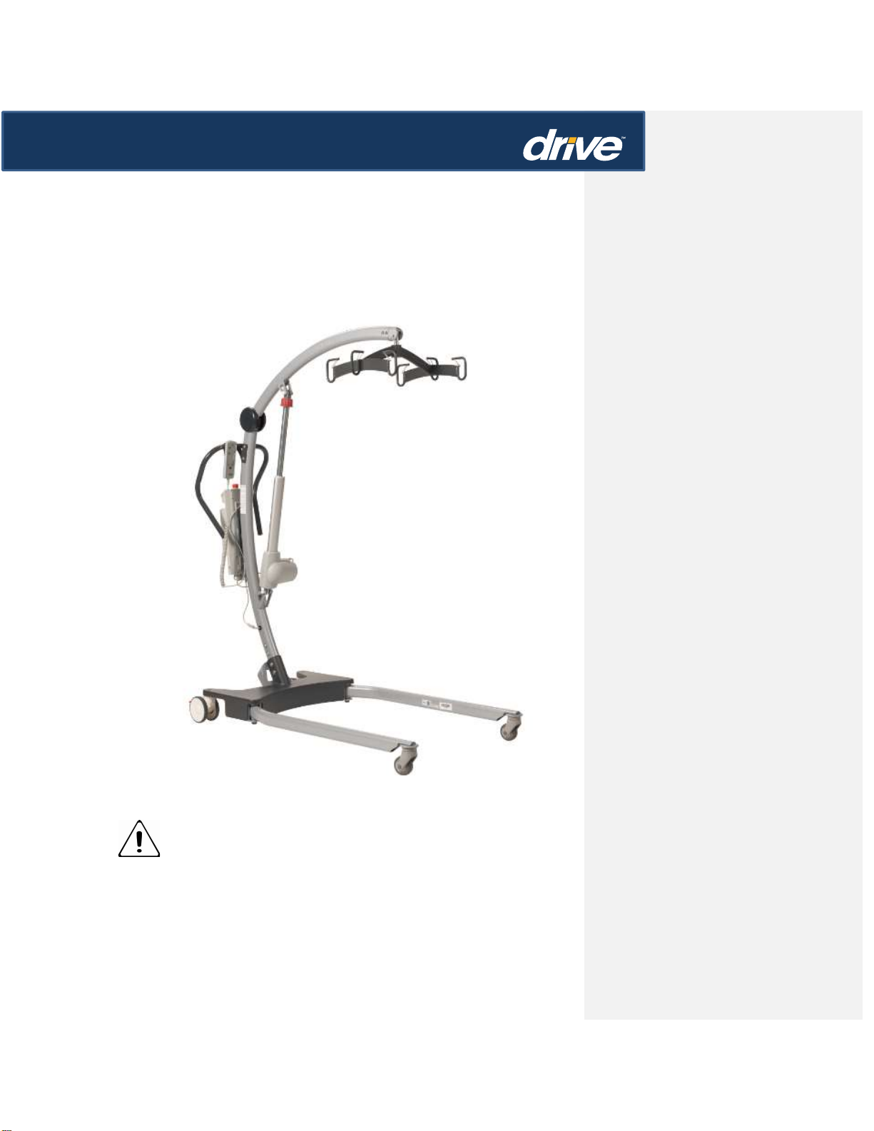
The Drive DeVilbiss Healthcare’s Levantar and Gravis Resident/Patient
Floor Lifts
Commented [SM1]: FPO

4
1. Introduction: About Your Lift
The Drive DeVilbiss Healthcare’s Levantar and Gravis floor lifts have a fresh contemporary look
with curved boom and mast and V-shaped legs which ensure a remarkable stability compared
to similar lifts, this feature makes it is possible to have a lifting capacity of, see chart below,
without comprising safety.
Product # Product Name Power/Manual Base Weight Capacity
FLNP500 LEVANTAR Manual 500 lbs
FLP500 LEVANTAR Power 500 lbs
FLNP600 GRAVIS Manual 600 lbs
FLP600 GRAVIS Power 600 lbs
Each Levantar/Gravis lift is fully assembled, load tested and certified before being
packed/shipped.
The packing is specifically designed for both export and domestic shipment to ensure the safe
arrival of the lift. A number of documents are supplied in a packet with each lift and should be
kept safely for future reference.
• TEST CERTIFICATE • USER MANUAL
The TEST CERTIFICATE is an important document and should be kept for reference purposes.
To properly maintain your lift please refer to the maintenance schedule included in this
document. If you are at all unsure what your country’s servicing requirements are, please check
with your dealer and/or a local government agency.

5
2. Statement of Intended Use
The intended use of this lifting device is for the safe lifting and transfer of an individual from one
resting surface to another (such as a bed to a wheelchair). Drive DeVilbiss Healthcare
recommends that the transfer of a patient is fully risk assessed and conducted safely over a
short distance only.
The Drive DeVilbiss Healthcare’s Levantar and Gravis lifts are suitable for patients in the
SITTING, SITTING/RECUMBENT and RECUMBENT positions.
The Drive DeVilbiss Healthcare Levantar/Gravis is an electrically operated patient lift, designed
to support and promote safe patient handling and transfer for both the patient and caregiver.
The Drive DeVilbiss Healthcare’s Levantar and Gravis lifts incorporates a 6-point cradle with
safety sling spring clips as standard and is designed to be used in conjunction with, and only,
Drive DeVilbiss branded range of slings. A 4-point cradle option is available as an add-on
accessory.
Expected Service Life
Drive DeVilbiss Healthcare’s Levantar and Gravis lifts are designed and tested for a minimum
service life of fifteen (15) years, subject to the use and maintenance procedures stated in this
manual. Use, other than in accordance with these instructions, may compromise service life.
6
3) Assembly Instructions
Carton Contents
Place the carton in a clear working area and open carefully. The carton contains:
• DRIVE DEVILBISS HEALTHCARE LEVANTAR OR GRAVIS FLOOR LIFT
MAST, BOOM, BASE, “U” SHAPPED PUSH HANDLE
• WALLET CONTAINING DOCUMENTS
• HAND CONTROL
• BATTERY PACK
• CHARGING CORD
• DESK TOP CHARGER/STAND
• FOR THOSE LIFTS THAT HAVE A MANUAL BASE – SPREADER BAR
Warning
The Drive DeVilbiss Healthcare’s Levantar and Gravis lifts are heavy and will need to be lifted
with care. You may need assistance to lift the product from the carton.
1. Remove all the parts from the carton and place on the floor, taking care to protect the finish
from damage.
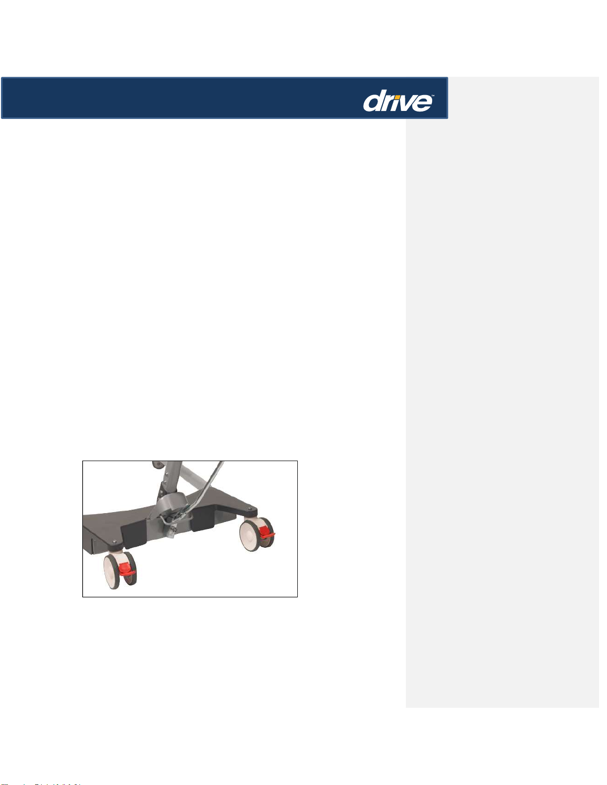
Place the base in a clear space and apply the rear brakes. If you are assembling a unit with a
power base, connect the two power base connectors before sliding mast into base. Be careful
not damaging the wire connectors.
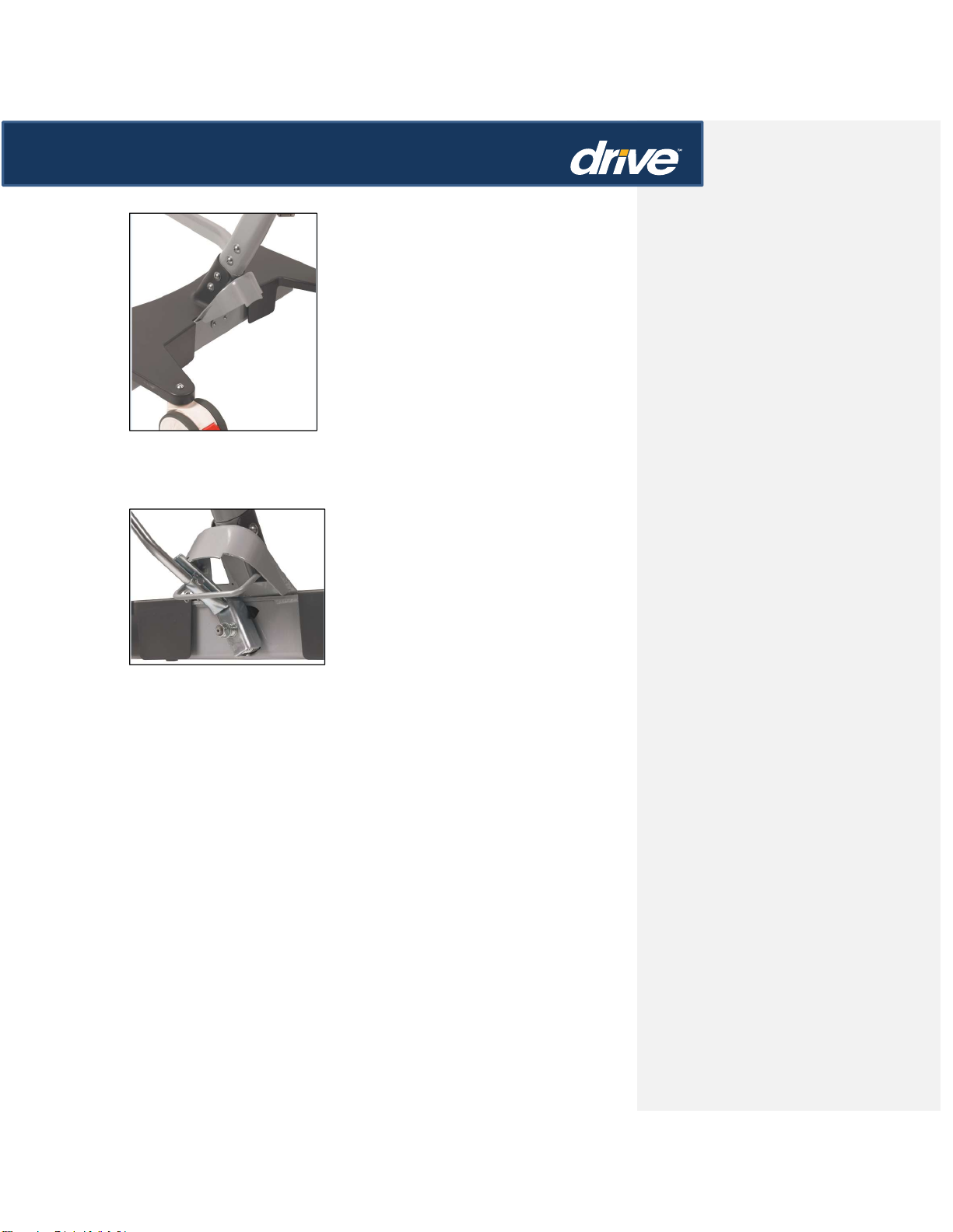
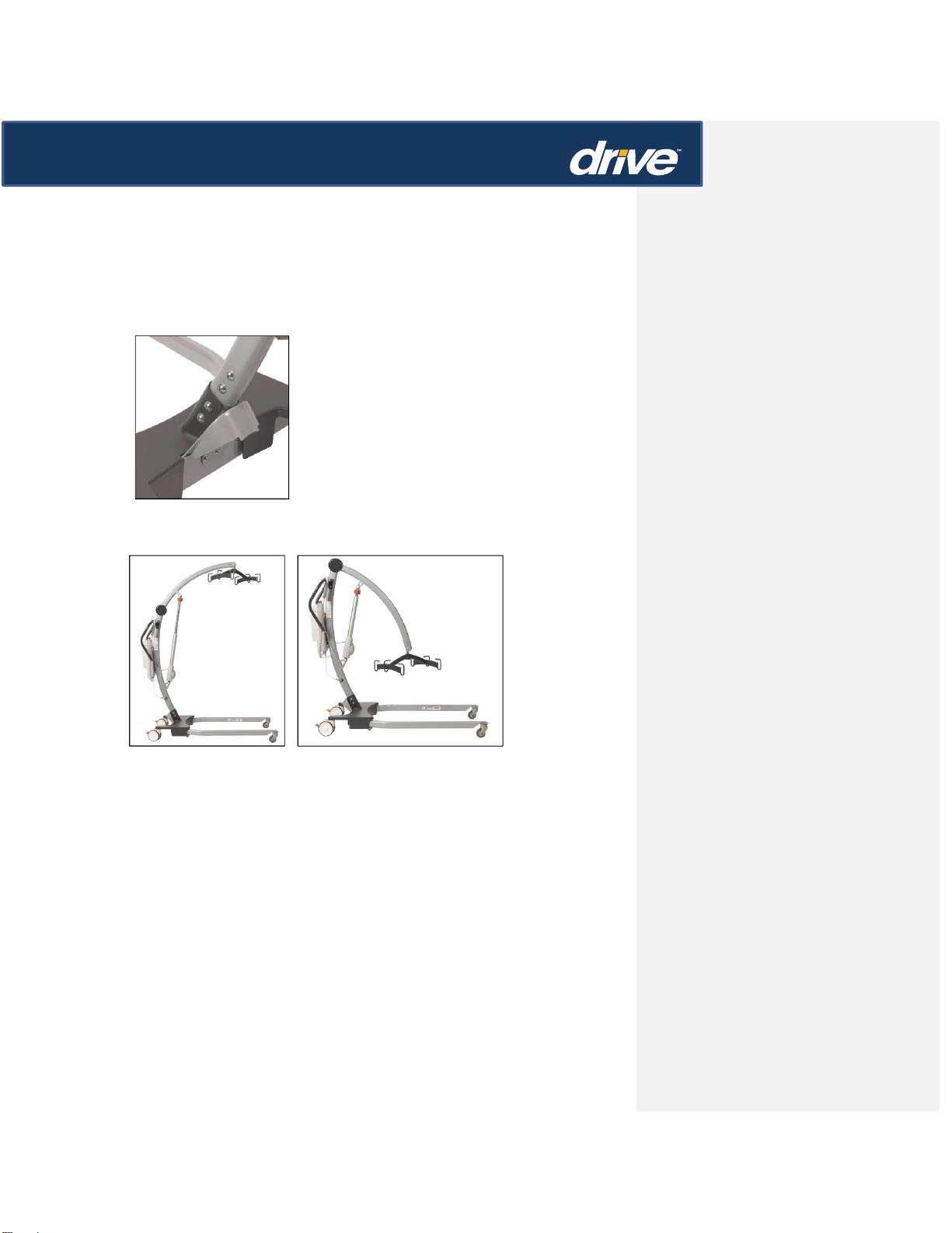
2. Fit the mast and boom assembly into the base socket
7
3. Secure the mast and boom assembly to the base with the four attachment bolts
4. If you are assembling the manual base, connect the manual leg adjustment handle to the
base.
Warning
Avoid trapping fingers. Keep fingers away from the end of the mast when inserting into
the base socket. Full engagement of the mast is indicated by the label on the side of
the mast. The electric leg operation will not function unless the mast is fully engaged.
6. Line the handle assembly up to the rear of the mast and attach using the two screws
provided. The screws needed to attach the handle are kept in the user instruction wallet

8
for safe keeping.
7. Fit power pack to the lift and make sure the latch holding the pack in place is fully engaged.
“Click” in place.
7. Plug the handset and actuator cables into the bottom of the controller. Refer to the figures on
page 13 for correct positions.
Disassembly
9
The lift should not be disassembled unless for service, repair or transport if necessary. If
disassembly is required, simply follow the assembly instructions in reverse sequence.
ALWAYS CHECK THE FOLLOWING BEFORE OPERATION
The mast is fully locked into position.
Confirm the boom rises and lowers (This is done via the hand control and/or control
module).
The legs of the lift open and close satisfactorily (This is done via the hand control
and/or control module).
The red Emergency Stop Button is located on the top of the control box and is activated
by pressing in. This will cut all power to the lift and only be reset by twisting the button
counter clockwise and releasing.
 Loading...