


 Loading...
VigorSwitch P2280x
PoE L2+ Managed Switch
User’s Guide
Version: 1.0 Firmware Version: V2.5.0 (For future update, please visit DrayTek web site) Date: July 26, 2019
ii |
VigorSwitch P2280x User’s Guide |
|
Copyrights
© All rights reserved. This publication contains information that is protected by copyright. No part may be reproduced, transmitted, transcribed, stored in a retrieval system, or translated into any language without written permission from the copyright holders.
Trademarks
The following trademarks are used in this document:
Microsoft is a registered trademark of Microsoft Corp.
Windows, Windows 95, 98, Me, NT, 2000, XP, Vista, 7, 8, 10 and Explorer are trademarks of Microsoft Corp.
Apple and Mac OS are registered trademarks of Apple Inc.
Other products may be trademarks or registered trademarks of their respective manufacturers.
Caution
Circuit devices are sensitive to static electricity, which can damage their delicate electronics. Dry weather conditions or walking across a carpeted floor may cause you to acquire a static electrical charge.
To protect your device, always:
Touch the metal chassis of your computer to ground the static electrical charge before you pick up the circuit device.
Pick up the device by holding it on the left and right edges only.
Warranty
We warrant to the original end user (purchaser) that the device will be free from any defects in workmanship or materials for a period of one (1) year from the date of purchase from the dealer. Please keep your purchase receipt in a safe place as it serves as proof of date of purchase. During the warranty period, and upon proof of purchase, should the product have indications of failure due to faulty workmanship and/or materials, we will, at our discretion, repair or replace the defective products or components, without charge for either parts or labor, to whatever extent we deem necessary tore-store the product to proper operating condition. Any replacement will consist of a new or re-manufactured functionally equivalent product of equal value, and will be offered solely at our discretion. This warranty will not apply if the product is modified, misused, tampered with, damaged by an act of God, or subjected to abnormal working conditions. The warranty does not cover the bundled or licensed software of other vendors. Defects which do not significantly affect the usability of the product will not be covered by the warranty. We reserve the right to revise the manual and online documentation and to make changes from time to time in the contents hereof without obligation to notify any person of such revision or changes.
Be a Registered Owner
Web registration is preferred. You can register your VigorSwitch via http://www.DrayTek.com.
Firmware & Tools Updates
Due to the continuous evolution of DrayTek technology, all routers will be regularly upgraded. Please consult the DrayTek web site for more information on newest firmware, tools and documents.
More update, please visit www.draytek.com.
VigorSwitch P2280x User’s Guide |
iii |
|
|
Table of Contents |
Part I Introduction.............................................................................................................. |
1 |
I-1 Introduction ................................................................................................................................... |
2 |
I-1-1 Key Features ....................................................................................................................... |
2 |
I-1-2 Specifications ...................................................................................................................... |
3 |
I-1-3 Packing List ......................................................................................................................... |
4 |
I-1-4 LED Indicators and Connectors .......................................................................................... |
4 |
I-2 Installation ..................................................................................................................................... |
6 |
I-2-1 Typical Applications............................................................................................................. |
6 |
I-2-2 Installing Network Cables.................................................................................................. |
10 |
I-2-3 Configuring the Management Agent of Switch.................................................................. |
10 |
I-2-4 Managing VigorSwitch P2280x through Ethernet Port...................................................... |
10 |
I-2-5 IP Address Assignment ..................................................................................................... |
11 |
I-3 Accessing Web Page of VigorSwitch .......................................................................................... |
15 |
I-4 Dashboard................................................................................................................................... |
16 |
I-5 Status .......................................................................................................................................... |
17 |
I-5-1 Port Bandwidth Utilization ................................................................................................. |
17 |
I-5-2 LLDP Statistics .................................................................................................................. |
17 |
I-5-3 GVRP Statistics ................................................................................................................. |
18 |
I-5-4 MLD Snooping Statistics ................................................................................................... |
18 |
I-5-5 Hardware Monitor.............................................................................................................. |
19 |
Part II Switch LAN............................................................................................................ |
21 |
II-1 General Setup............................................................................................................................ |
22 |
II-1-1 IP Address ........................................................................................................................ |
22 |
II-1-2 IPv6 Address .................................................................................................................... |
23 |
II-1-3 Management VLAN .......................................................................................................... |
24 |
II-2 Port Setting ................................................................................................................................ |
25 |
II-2-1 General Setting................................................................................................................. |
25 |
II-2-1-1 Port Settings (Coax Port 1..24) ........................................................ |
25 |
II-2-1-2 Port Settings (Fiber Port 25..28) ...................................................... |
27 |
II-2-2 Protected Ports................................................................................................................. |
29 |
II-3 Mirror.......................................................................................................................................... |
30 |
II-4 Link Aggregation ........................................................................................................................ |
31 |
II-4-1 LAG Setting ...................................................................................................................... |
31 |
II-4-2 LAG Management ............................................................................................................ |
32 |
II-4-3 LAG Port Setting............................................................................................................... |
33 |
II-4-4 LACP Setting .................................................................................................................... |
35 |
II-4-5 LACP Port Setting ............................................................................................................ |
36 |
II-5 VLAN Management.................................................................................................................... |
37 |
II-5-1 Create VLAN .................................................................................................................... |
37 |
|
VigorSwitch P2280x User’s Guide |
iv |
|
II-5-2 Interface Settings.............................................................................................................. |
38 |
II-5-3 Voice VLAN ...................................................................................................................... |
40 |
II-5-3-1 Properties ................................................................................. |
40 |
II-5-3-2 Telephony OUI Setting .................................................................. |
41 |
II-5-3-3 Port Setting ............................................................................... |
42 |
II-5-4 MAC VLAN ....................................................................................................................... |
43 |
II-5-4-1 MAC Group ................................................................................ |
43 |
II-5-4-3 Group Binding ............................................................................ |
43 |
II-5-5 Protocol VLAN .................................................................................................................. |
45 |
II-5-5-1 Protocol Group ........................................................................... |
45 |
II-5-5-2 Group Binding ............................................................................ |
46 |
II-5-6 Surveillance VLAN............................................................................................................ |
48 |
II-5-6-1 Property ................................................................................... |
48 |
II-5-6-2 Surveillance OUI.......................................................................... |
50 |
II-5-7 GVRP ............................................................................................................................... |
51 |
II-5-7-1 Property ................................................................................... |
51 |
II-5-7-2 Membership ............................................................................... |
52 |
II-6 EEE ............................................................................................................................................ |
53 |
II-7 Multicast ..................................................................................................................................... |
54 |
II-7-1 Properties ......................................................................................................................... |
54 |
II-7-2 IGMP Snooping ................................................................................................................ |
56 |
II-7-2-1 IGMP Setting .............................................................................. |
56 |
II-7-2-2 IGMP Querier Setting.................................................................... |
58 |
II-7-2-3 IGMP Static Group ....................................................................... |
59 |
II-7-2-4 IGMP Group Table........................................................................ |
60 |
II-7-2-5 IGMP Router Table....................................................................... |
61 |
II-7-2-6 Forward All ............................................................................... |
62 |
II-7-2-7 Throttling ................................................................................. |
63 |
II-7-2-8 Filtering Profile .......................................................................... |
64 |
II-7-2-9 Filtering Binding ......................................................................... |
65 |
II-7-3 MVR.................................................................................................................................. |
67 |
II-7-3-1 Property ................................................................................... |
67 |
II-7-3-2 Port Setting ............................................................................... |
68 |
II-7-3-3 Group Address ............................................................................ |
69 |
II-7-4 MLD Snooping.................................................................................................................. |
70 |
II-7-4-1 MLD Setting ............................................................................... |
70 |
II-7-4-2 MLD Static Group ........................................................................ |
72 |
II-7-4-3 MLD Group Table......................................................................... |
73 |
II-7-4-4 MLD Router Table........................................................................ |
74 |
II-7-4-5 Forward All ............................................................................... |
75 |
II-7-4-6 Throttling ................................................................................. |
76 |
II-7-4-7 Filtering Profile .......................................................................... |
77 |
II-7-4-8 Filtering Binding ......................................................................... |
78 |
II-8 Jumbo Frame............................................................................................................................. |
80 |
II-9 STP ............................................................................................................................................ |
81 |
II-9-1 Properties ......................................................................................................................... |
81 |
II-9-2 Port Setting....................................................................................................................... |
82 |
II-9-3 Bridge Setting ................................................................................................................... |
84 |
II-9-4 Port Advanced Setting...................................................................................................... |
85 |
II-9-5 Statistics ........................................................................................................................... |
86 |
VigorSwitch P2280x User’s Guide |
|
|
v |
II-9-6 MST Instance ................................................................................................................... |
87 |
II-9-7 MST Port Setting .............................................................................................................. |
88 |
II-10 MAC Address Table.................................................................................................................. |
90 |
II-10-1 Static MAC Setting ......................................................................................................... |
90 |
II-10-2 Dynamic Address Setting ............................................................................................... |
91 |
II-10-3 Dynamic Learned ........................................................................................................... |
92 |
II-11 Blocked Port Recover............................................................................................................... |
93 |
Part III ONVIF Surveillance.............................................................................................. |
95 |
III-1 Discovery .................................................................................................................................. |
96 |
III-2 Topology.................................................................................................................................... |
97 |
III-2-1 Status .............................................................................................................................. |
97 |
III-2-2 Throughput Threshold ................................................................................................... |
101 |
III-3 Video ....................................................................................................................................... |
103 |
III-4 Device Maintenance ............................................................................................................... |
104 |
III-4-1 General.......................................................................................................................... |
104 |
III-4-1 Network ......................................................................................................................... |
106 |
III-4-3 Security.......................................................................................................................... |
107 |
Part IV VLAN Routing .................................................................................................... |
109 |
IV-1 Property ................................................................................................................................... |
110 |
IV-2 Interface Setting....................................................................................................................... |
111 |
IV-3 Static Route.............................................................................................................................. |
112 |
Part V Security ............................................................................................................... |
113 |
V-1 RADIUS .................................................................................................................................... |
114 |
V-2 TACACS+.................................................................................................................................. |
116 |
V-3 Management Access Authentication......................................................................................... |
117 |
V-3-1 Method Profile ................................................................................................................ |
117 |
V-3-2 Application Authentication.............................................................................................. |
119 |
V-4 Management Access Control................................................................................................... |
120 |
V-4-1 Management Access Control Profile (ACL) ................................................................... |
120 |
V-4-2 Management Access Control Entries (ACE).................................................................. |
121 |
V-5 802.1X/MAC Authentication..................................................................................................... |
123 |
V-5-1 Properties....................................................................................................................... |
123 |
V-5-1-1 Global Settings ......................................................................... |
123 |
V-5-1-2 Port Authentication Setting.......................................................... |
124 |
V-5-2 Port Control/Settings...................................................................................................... |
125 |
V-5-3 MAC-Based Local Account ............................................................................................ |
127 |
V-5-4 Authenticated Hosts....................................................................................................... |
128 |
V-5-5 Accounting ..................................................................................................................... |
129 |
V-6 Port Security ............................................................................................................................ |
130 |
V-7 Storm Control........................................................................................................................... |
132 |
|
VigorSwitch P2280x User’s Guide |
vi |
|
V-7-1 Properties....................................................................................................................... |
132 |
V-7-2 Port Setting .................................................................................................................... |
133 |
V-8 DoS .......................................................................................................................................... |
134 |
V-8-1 Properties....................................................................................................................... |
134 |
V-8-2 DoS Port Setting ............................................................................................................ |
136 |
V-9 Dynamic ARP Inspection ......................................................................................................... |
137 |
V-9-1 Properties....................................................................................................................... |
137 |
V-9-1-1 Global Property Settings ............................................................. |
137 |
V-9-1-2 Per Port Property Settings ........................................................... |
138 |
V-9-2 Statistics......................................................................................................................... |
139 |
V-10 DHCP Snooping..................................................................................................................... |
140 |
V-10-1 Properties..................................................................................................................... |
140 |
V-10-1-1 Global Property Settings ............................................................ |
140 |
V-10-1-2 Per Port Property Settings .......................................................... |
141 |
V-10-2 Statistics....................................................................................................................... |
142 |
V-10-3 Option82 Property........................................................................................................ |
142 |
V-10-3-1 Global Option82 Property Settings ................................................ |
142 |
V-10-3-2 Per Port Option82 Property Settings .............................................. |
143 |
V-10-4 Option82 Circuit ID....................................................................................................... |
144 |
V-11 IP Source Guard .................................................................................................................... |
145 |
V-11-1 Port Settings................................................................................................................. |
145 |
V-11-2 IMPV Binding ............................................................................................................... |
146 |
V-12 IP Conflict Prevention ............................................................................................................ |
148 |
V-13 Loop Protection...................................................................................................................... |
152 |
Part VI ACL Configuration............................................................................................. |
153 |
VI-1 Create ACL ............................................................................................................................. |
154 |
VI-1-1 MAC .............................................................................................................................. |
154 |
VI-1-2 IPv4 ............................................................................................................................... |
155 |
VI-1-3 IPv6 ............................................................................................................................... |
156 |
VI-2 Create ACE............................................................................................................................. |
157 |
VI-2-1 MAC .............................................................................................................................. |
157 |
VI-2-2 IPv4 ............................................................................................................................... |
158 |
VI-2-3 IPv6 ............................................................................................................................... |
160 |
VI-3 ACL Binding ............................................................................................................................ |
162 |
Part VII QoS Configuration............................................................................................ |
163 |
VII-1 General .................................................................................................................................. |
164 |
VII-1-1 Properties..................................................................................................................... |
164 |
VII-1-1-1 QoS General Setting ................................................................. |
164 |
VII-1-1-2 Trust Ports............................................................................. |
165 |
VII-1-2 Port Settings................................................................................................................. |
166 |
VII-1-3 Queue Settings ............................................................................................................ |
167 |
VII-1-4 CoS Mapping ............................................................................................................... |
168 |
VigorSwitch P2280x User’s Guide |
|
|
vii |
VII-1-5 DSCP Mapping ............................................................................................................ |
169 |
VII-1-6 IP Precedence Mapping............................................................................................... |
170 |
VII-2 Bandwidth .............................................................................................................................. |
171 |
VII-2-1 Ingress Rate Limit ........................................................................................................ |
171 |
VII-2-2 Egress Shaping Rate ................................................................................................... |
172 |
VII-2-3 Egress Shaping Per Queue ......................................................................................... |
173 |
Part VIII PoE Configuration ........................................................................................... |
175 |
VIII-1 Properties ............................................................................................................................. |
176 |
VIII-2 Status.................................................................................................................................... |
177 |
VIII-3 Schedule............................................................................................................................... |
178 |
VIII-3-1 Schedule Profile.......................................................................................................... |
178 |
VIII-3-2 Port Scheduling........................................................................................................... |
179 |
Part IX System Maintenance ......................................................................................... |
181 |
IX-1 TR-069.................................................................................................................................... |
182 |
IX-2 OpenVPN................................................................................................................................ |
184 |
IX-3 Webhook................................................................................................................................. |
185 |
IX-4 LLDP....................................................................................................................................... |
186 |
IX-4-1 Properties...................................................................................................................... |
186 |
IX-4-2 LLDP Port Setting ......................................................................................................... |
187 |
IX-4-3 LLDP Local Device........................................................................................................ |
188 |
IX-4-4 MED Network Policy ..................................................................................................... |
189 |
IX-4-5 LLDP MED Port Settings .............................................................................................. |
190 |
IX-4-6 LLDP Remote Device.................................................................................................... |
191 |
IX-4-7 LLDP Overloading......................................................................................................... |
192 |
IX-5 SNMP ..................................................................................................................................... |
193 |
IX-5-1 View............................................................................................................................... |
194 |
IX-5-2 Group ............................................................................................................................ |
195 |
IX-5-3 Community .................................................................................................................... |
196 |
IX-5-4 User............................................................................................................................... |
197 |
IX-5-5 Engine ID ...................................................................................................................... |
199 |
IX-5-5-1 Local Engine ID ........................................................................ |
199 |
IX-5-5-2 Remote Engine ID ..................................................................... |
200 |
IX-5-6 Trap Event..................................................................................................................... |
201 |
IX-5-7 Notification .................................................................................................................... |
202 |
IX-6 sFlow ...................................................................................................................................... |
204 |
IX-7 Access Manager ..................................................................................................................... |
206 |
IX-8 Time and Date ........................................................................................................................ |
207 |
IX-8-1 System Time Zone........................................................................................................ |
207 |
IX-8-2 Time .............................................................................................................................. |
208 |
IX-9 Backup Manager..................................................................................................................... |
209 |
|
VigorSwitch P2280x User’s Guide |
viii |
|
IX-10 Upgrade Manager................................................................................................................. |
210 |
IX-11 Firmware Information............................................................................................................. |
211 |
IX-12 Account Manager.................................................................................................................. |
212 |
IX-13 Factory Default ..................................................................................................................... |
214 |
IX-14 Reboot Switch....................................................................................................................... |
215 |
Part X Diagnostics ......................................................................................................... |
217 |
X-1 Device Check........................................................................................................................... |
218 |
X-2 Cable Diagnostics.................................................................................................................... |
219 |
X-3 Ping Test .................................................................................................................................. |
220 |
X-4 SysLog..................................................................................................................................... |
221 |
X-4-1 SysLog Explorer............................................................................................................. |
221 |
X-4-2 SysLog Settings ............................................................................................................. |
222 |
X-4-2-1 SysLog Service .......................................................................... |
222 |
X-4-2-2 Local SysLog............................................................................. |
223 |
X-4-2-3 Remote SysLog.......................................................................... |
224 |
X-4-2-4 SysLog Mail.............................................................................. |
225 |
X-5 Fan Test ................................................................................................................................... |
227 |
X-6 Route Table.............................................................................................................................. |
228 |
Part XI Mail Alert ............................................................................................................ |
229 |
XI-1 Alert Setting ............................................................................................................................ |
230 |
Part XII Telnet Commands............................................................................................. |
233 |
XII-1 Accessing Telnet of VigorSwitch............................................................................................ |
234 |
XII-2 Available Commands............................................................................................................. |
236 |
XII-2-1 Clear Configuration ...................................................................................................... |
236 |
XII-2-2 Clock Configuration...................................................................................................... |
245 |
XII-2-3 Configure Configuration ............................................................................................... |
246 |
XII-2-4 Copy Configuration ...................................................................................................... |
334 |
XII-2-5 Delete Configuration .................................................................................................... |
335 |
XII-2-6 Disable Configuration................................................................................................... |
336 |
XII-2-7 End Configuration ........................................................................................................ |
336 |
XII-2-8 Exit Configuration......................................................................................................... |
336 |
XII-2-9 Ping Configuration........................................................................................................ |
337 |
XII-2-10 Reboot Configuration ................................................................................................. |
337 |
XII-2-11 Renew Configuration ................................................................................................. |
338 |
XII-2-12 Restore-defaults Configuration .................................................................................. |
338 |
XII-2-13 Save Configuration..................................................................................................... |
338 |
XII-2-14 Show Configuration.................................................................................................... |
339 |
XII-2-15 SSL Configuration...................................................................................................... |
340 |
XII-2-16 Terminal Configuration............................................................................................... |
340 |
XII-2-17 Traceroute Configuration ........................................................................................... |
341 |
VigorSwitch P2280x User’s Guide |
|
|
ix |
|
XII-2-18 UDLD Configuration................................................................................................... |
341 |
Appendix: Reference..................................................................................................... |
343 |
|
A-1 |
What’s the Ethernet ................................................................................................................. |
344 |
A-2 |
Media Access Control (MAC) .................................................................................................. |
347 |
A-3 |
Flow Control............................................................................................................................. |
351 |
Index ............................................................................................................................... |
|
354 |
x |
VigorSwitch P2280x User’s Guide |
|
Part I Introduction
VigorSwitch P2280x User’s Guide

I-1 Introduction
VigorSwitch P2280x, 24 Ports + 4 Combo UTP/SFP Ports PoE L2+ Managed Gigabit Switch, is a standard switch that meets all IEEE 802.3/u/x/z Gigabit, Fast Ethernet specifications. The switch has 24 10/100/1000Mbps TP ports. It supports telnet, http, https, SSH and SNMP interface for switch management. The network administrator can login the switch to monitor, configure and control each port’s activity. In addition, the switch implements the QoS (Quality of Service), VLAN, and Trunking. It is suitable for office application.
VigorSwitch supports IEEE 802.3az, Energy-Efficient Ethernet, and provides power saving feature. It can efficiently save the switch power with auto detect the client idle and cable length to provide different power.
1000Mbps SFP Fiber port fully complies with all IEEE 802.3z and 1000Base-SX/LX standards.
I-1-1 Key Features
Below shows key features of this device:
QoS
The switch offers powerful QoS function. This function supports 802.1p VLAN tag priority and DSCP on Layer 3 of network framework.
VLAN
Support Port-based VLAN and IEEE802.1Q Tag VLAN. Support 24 active VLANs and VLAN ID 1~4094.
Port Trunking
Allows one or more links to be aggregated together to form a Link Aggregation Group by the static setting.
Power Saving
The Power saving using the IEEE 802.3az, Energy-Efficient Ethernet to detect the client idle and cable length automatically and provides the different power. It could efficient to save the switch power and reduce the power consumption.
2 |
VigorSwitch P2280x User’s Guide |

I-1-2 Specifications
The VigorSwitch P2280x, a standalone off-the-shelf switch, provides the comprehensive features listed below for users to perform system network administration and efficiently and securely serve your network.
Hardware
24 10/100/1000Mbps Auto-negotiation Gigabit Ethernet TP ports with PoE+
Jumbo frame support 12KB
4 UTP/SFP Ethernet Ports
Programmable classifier for QoS (Layer 2/Layer 3)
16K MAC address and support VLAN ID(1~4094)
Per-port shaping, policing, and Broadcast Storm Control
Power Saving with IEEE 802.3az, Energy-Efficient Ethernet
Full-duplex flow control (IEEE802.3x) and half-duplex backpressure
Extensive front-panel diagnostic LEDs; Power, System, PoE fail and PoE/link activity
Hardware reset button for resetting configuration to factory default by pressing over 5 seconds
Management
Supports per port traffic monitoring counters
Supports a snapshot of the system Information when you login
Supports port mirror function
Supports the static trunk function
Supports 802.1Q VLAN
Supports user management and limits three users to login
Maximal packet length can be up to 9600 bytes for jumbo frame application
Supports Broadcasting Suppression to avoid network suspended or crashed
Supports to send the trap event while monitored events happened
Supports default configuration which can be restored to overwrite the current configuration which is working on via Web UI and Reset button of the switch
Supports on-line plug/unplug SFP modules
Supports Quality of Service (QoS) for real time applications based on the information taken from Layer 2 to Layer 3
Built-in web-based management and CLI management, providing a more convenient UI for the user
VigorSwitch P2280x User’s Guide |
3 |

I-1-3 Packing List
Before you start installing the switch, verify that the package contains the following:
VigorSwitch P2280x
AC Power Cord
Quick Start Guide
Rubber feet
Rack mount kit
Please notify your sales representative immediately if any of the aforementioned items is missing or damaged.
I-1-4 LED Indicators and Connectors
Before you use the Vigor device, please get acquainted with the LED indicators and connectors first. There are 8 Ethernet ports and SFP ports on the front panel of the switch. LED display area, locating on the front panel, contains an ACT, Power LED and ports working status of the switch.
|
Port 1 to 24 (PoE) |
Port 25 to 28 |
||
LED Explanation |
|
|
||
|
|
(SFP+) |
||
|
|
|
|
|
|
|
|
|
|
|
|
|
|
|
 Port 1 to 24 (GbE RJ45)
|
LED |
Color |
Explanation |
|
|
|
|
|
|
|
|
On (Red) |
An alert for system failure due to overheating or |
|
|
|
wrong voltage. |
||
|
Monitor |
|
||
|
|
|
|
|
|
Off |
The device is in normal condition and running |
||
|
|
|||
|
|
normally. |
||
|
|
|
||
|
|
|
|
|
|
|
Blinking (Green) |
The power is over (>) 80% watts PoE power budget. |
|
|
|
|
|
|
|
Alert |
Off |
The power is under (<) 80% watts PoE power |
|
|
|
budget. |
||
|
|
|
||
|
|
|
|
|
|
|
On (Green) |
The switch finishes system booting and the system |
|
|
|
is ready. |
||
|
|
|
||
|
|
|
|
|
|
SYS |
Blinking (Green) |
The switch is powered on and starts system |
|
|
booting. |
|||
|
|
|
||
|
|
|
|
|
|
|
Off |
The power is off or the system is not ready / |
|
|
|
malfunctioning. |
||
|
|
|
||
|
|
|
|
|
|
PWR |
On (Green) |
The device is powered on and running normally. |
|
|
|
|
|
|
|
Off |
The device is not ready or is failed. |
||
|
|
|||
|
|
|
|
|
|
PoE 1~24 |
On (Green) |
The port is supplied with PoE power. |
|
|
|
|
|
|
4 |
|
|
VigorSwitch P2280x User’s Guide |
|

|
Off |
No PoE power is supplied on the port. |
|
|
|
|
|
|
On (Green) |
The device is connected with 1000Mbps. |
|
|
|
|
|
Port 1 ~ 24 |
On (Amber) |
The device is connected with 10/100Mbps. |
|
|
|
||
Blinking |
The system is sending or receiving data through |
||
(GbE RJ45) |
|||
|
the port. |
||
|
|
||
|
|
|
|
|
Off |
The port is disconnected or the link is failed. |
|
|
|
|
|
|
On (Green) |
The device is connected with 1000Mbps. |
|
|
|
|
|
|
On (Blue) |
The device is connected with 10Gbps. |
|
Port 25 ~ 28 |
|
|
|
On (Amber) |
The device is connected with 10/100Mbps. |
||
(SFP+) |
|
|
|
Blinking |
The system is sending or receiving data through |
||
|
|
the port. |
|
|
|
|
|
|
Off |
The port is disconnected or the link is failed. |
|
|
|
|
Connector Explanation
|
Interface |
|
Description |
|
|
|
|
|
Port 1 ~ 24 |
(GbE RJ45) |
Port 1 to Port 24 can be used for Ethernet |
|
|
|
connection and PoE connection, depending on the |
|
Port 1 ~ 24 |
(PoE) |
|
|
device connected. |
||
|
|
|
|
|
Port 25 ~ 28 (SFP+) |
Port 25 to Port 28 are used for fiber connection. |
|
|
|
||
|
|
|
|
|
Console |
|
Used to perform telnet command control. |
|
|
|
|
|
|
|
|
|
|
|
Power inlet for AC input (100~240V/AC, 50/60Hz). |
|
|
|
|
Note:
Power Output –
IEEE 802.3af Max. 15.4W Output Supported
IEEE 802.3at Max. 30W Output Supported PoE Power Budget--
400 Watts (Max)
VigorSwitch P2280x User’s Guide |
5 |

I-2 Installation
I-2-1 Typical Applications
The VigorSwitch implements 24 Gigabit Ethernet TP ports with auto MDIX and four slots for the removable module supporting comprehensive fiber types of connection, including LC and BiDi-LC SFP modules. The switch is suitable for the following applications:
Case 1: All switch ports are in the same local area network.
Every port can access each other. (*The switch image is sample only.)
If VLAN is enabled and configured, each node in the network that can communicate each other directly is bounded in the same VLAN area.
Here VLAN area is defined by what VLAN you are using. The switch supports both port-based VLAN and tag-based VLAN. They are different in practical deployment, especially in physical location. The following diagram shows how it works and what the difference they are.
Case 2: Port-based VLAN -1 (*The switch image is sample only.)
6 |
VigorSwitch P2280x User’s Guide |

The same VLAN members could not be in different switches.
Every VLAN members could not access VLAN members each other.
The switch manager has to assign different names for each VLAN groups at one switch.
Case 3: Port-based VLAN - 2
VLAN1 members could not access VLAN2, VLAN3 and VLAN4 members.
VLAN2 members could not access VLAN1 and VLAN3 members, but they could access VLAN4 members.
VLAN3 members could not access VLAN1, VLAN2 and VLAN4.
VLAN4 members could not access VLAN1 and VLAN3 members, but they could access VLAN2 members.
Case 4: The same VLAN members can be at different switches with the same VID
VigorSwitch P2280x User’s Guide |
7 |

Case 5: Desktop Installation
1.Install the switch on a level surface that can support the weight of the unit and the relevant components.
2.Plug the switch with the female end of the provided power cord and plug the male end to the power outlet.
Case 6: Rack-mount Installation
The switch may be standalone, or mounted in a rack. Rack mounting facilitate to an orderly installation when you are going to install series of networking devices.
Procedures to Rack-mount the switch:
1.Disconnect all the cables from the switch before continuing.
2.Place the unit the right way up on a hard, flat surface with the front facing you.
3.Locate a mounting bracket over the mounting holes on one side of the unit.
4.Insert the screws and fully tighten with a suitable screwdriver.
5.Repeat the two previous steps for the other side of the unit.
6.Insert the unit into the rack and secure with suitable screws.
7.Reconnect all the cables.
Case 7: Central Site/Remote site application is used in carrier or ISP
8 |
VigorSwitch P2280x User’s Guide |

Case 8: Peer-to-peer application is used in two remote offices
Case 9: Office network
VigorSwitch P2280x User’s Guide |
9 |

I-2-2 Installing Network Cables
Crossover or straight-through cable: All the ports on the switch support Auto-MDI/MDI-X functionality. Both straight-through or crossover cables can be used as the media to connect the switch with PCs as well as other devices like switches, hubs or router.
Category 3, 4, 5 or 5e, 6 UTP/STP cable: To make a valid connection and obtain the optimal performance, an appropriate cable that corresponds to different transmitting/receiving speed is required. To choose a suitable cable, please refer to the following table.
Media |
Speed |
Wiring |
|
|
|
|
|
10/100/1000 |
10 Mbps |
Category 3,4,5 UTP/STP |
|
|
|
||
100Mbps |
Category 5 UTP/STP |
||
Mbps copper |
|||
|
|
||
1000 Mbps |
Category 5e, 6 UTP/STP |
||
|
|||
|
|
|
I-2-3 Configuring the Management Agent of Switch
Users can monitor and configure the switch through the following procedures. Configuring the Management Agent of VigorSwitch P2280x through the Ethernet Port.
There are several ways to configure and monitor the switch through Ethernet port, includes Web-UI and SNMP.
I-2-4 Managing VigorSwitch P2280x through Ethernet Port
Before start using the switch, the IP address setting of the switch should be done, then perform the following steps:
1.Set up a physical path between the configured the switch and a PC by a qualified UTP Cat. 5e cable with RJ-45 connector.
Note: If PC directly connects to the switch, you have to setup the same subnet mask between them. But, subnet mask may be different for the PC in the remote site. Please refer to the above figure about the Web Smart Switch default IP address information.
10 |
VigorSwitch P2280x User’s Guide |
2.After configuring correct IP address on your PC, open your web browser and access switch's IP address.
Default system account is "admin", with password "admin" in default. Switch IP address is "192.168.1.224" by default with DHCP client enabled.
I-2-5 IP Address Assignment
For IP address configuration, there are three parameters needed to be filled in. They are IP address, Subnet Mask, Default Gateway and DNS.
IP address:
The address of the network device in the network is used for internetworking communication. Its address structure looks is shown below. It is “classful” because it is split into predefined address classes or categories.
Each class has its own network range between the network identifier and host identifier in the 32 bits address. Each IP address comprises two parts: network identifier (address) and host identifier (address). The former indicates the network where the addressed host resides, and the latter indicates the individual host in the network which the address of host refers to. And the host identifier must be unique in the same LAN. Here the term of IP address we used is version 4, known as IPv4.
Network identifier |
Host identifier |
|
|
32 bits
With the classful addressing, it divides IP address into three classes, class A, class B and class C. The rest of IP addresses are for multicast and broadcast. The bit length of the network prefix is the same as that of the subnet mask and is denoted as IP address/X, for example, 192.168.1.0/24. Each class has its address range described below.
Class A:
Address is less than 126.255.255.255. There are a total of 126 networks can be defined because the address 0.0.0.0 is reserved for default route and 127.0.0.0/8 is reserved for loopback function.
Class B:
IP address range between 128.0.0.0 and 191.255.255.255. Each class B network has a 16-bit network prefix followed 16-bit host address. There are 16,384 (2^14)/16 networks able to be defined with a maximum of 65534 (2^16 –2) hosts per network.
VigorSwitch P2280x User’s Guide |
11 |

Class C:
IP address range between 192.0.0.0 and 223.255.255.255. Each class C network has a 24-bit network prefix followed 8-bit host address. There are 2,097,152 (2^21)/24 networks able to be defined with a maximum of 254 (2^8 –2) hosts per network.
Class D and E:
Class D is a class with first 4 MSB (Most significance bit) set to 1-1-1-0 and is used for IP Multicast. See also RFC 1112. Class E is a class with first 4 MSB set to 1-1-1-1 and is used for IP broadcast.
According to IANA (Internet Assigned Numbers Authority), there are three specific IP address blocks reserved and able to be used for extending internal network. We call it Private IP address and list below:
Class A |
---10.0.0.0 |
10.255.255.255 |
|
|
|
Class B |
172.16.0.0 --- |
172.31.255.255 |
|
|
|
Class C |
192.168.0.0 |
--- 192.168.255.255 |
|
|
|
Please refer to RFC 1597 and RFC 1466 for more information.
Subnet mask:
It means the sub-division of a class-based network or a CIDR block. The subnet is used to determine how to split an IP address to the network prefix and the host address in bitwise basis. It is designed to utilize IP address more efficiently and ease to manage IP network.
For a class B network, 128.1.2.3, it may have a subnet mask 255.255.0.0 in default, in which the first two bytes is with all 1s. This means more than 60 thousands of nodes in flat IP address will be at the same network. It’s too large to manage practically. Now if we divide it into smaller network by extending network prefix from 16 bits to, say 24 bits, that’s using its third byte to subnet this class B network. Now it has a subnet mask 255.255.255.0, in which each bit of the first three bytes is 1. It’s now clear that the first two bytes is used to identify the class B network, the third byte is used to identify the subnet within this class B network and, of course, the last byte is the host number.
Not all IP address is available in the sub-netted network. Two special addresses are reserved. They are the addresses with all zero’s and all one’s host number. For example, an IP address 128.1.2.128, what IP address reserved will be looked like? All 0s mean the network itself, and all 1s mean IP broadcast.
12 |
VigorSwitch P2280x User’s Guide |
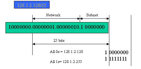
In this diagram, you can see the subnet mask with 25-bit long, 255.255.255.128, contains 126 members in the sub-netted network. Another is that the length of network prefix equals the number of the bit with 1s in that subnet mask. With this, you can easily count the number of IP addresses matched. The following table shows the result.
Prefix Length |
No. of IP matched No. of Addressable IP |
|
/32 |
1 |
- |
/31 |
2 |
- |
/30 |
4 |
2 |
/29 |
8 |
6 |
/28 |
16 |
14 |
/27 |
32 |
30 |
/26 |
64 |
62 |
/25 |
128 |
126 |
/24 |
256 |
254 |
/23 |
512 |
510 |
/22 |
1024 |
1022 |
/21 |
2048 |
2046 |
/20 |
4096 |
4094 |
/19 |
8192 |
8190 |
/18 |
16384 |
16382 |
/17 |
32768 |
32766 |
/16 |
65536 |
65534 |
|
|
|
According to the scheme above, a subnet mask 255.255.255.0 will partition a network with the class C. It means there will have a maximum of 254 effective nodes existed in this sub-netted network and is considered a physical network in an autonomous network. So it owns a network IP address which may looks like 168.1.2.0.
With the subnet mask, a bigger network can be cut into small pieces of network. If we want to have more than two independent networks in a worknet, a partition to the network must be performed. In this case, subnet mask must be applied.
For different network applications, the subnet mask may look like 255.255.255.240. This means it is a small network accommodating a maximum of 15 nodes in the network.
VigorSwitch P2280x User’s Guide |
13 |
For assigning an IP address to the switch, you just have to check what the IP address of the network will be connected with the switch. Use the same network address and append your host address to it.
First, IP Address: as shown above, enter “192.168.1.224”, for instance. For sure, an IP address such as 192.168.1.x must be set on your PC.
Second, Subnet Mask: as shown above, enter “255.255.255.0”. Choose a subnet mask suitable for your network.
Note: The DHCP Setting is enabled in default. Therefore, if a DHCP server presented on network connected to the switch, check before accessing your switch is essential.
14 |
VigorSwitch P2280x User’s Guide |

I-3 Accessing Web Page of VigorSwitch
1.Open any browser (e.g., Firefox) and type “192.168.1.224” as URL.
2.Please type “admin/admin” as the Username/Password and click Login.
3.Now, the Main Screen will appear.
Info |
The DHCP Setting is enabled in default. Therefore, if a DHCP server presented on |
|
network connected to VigorSwitch, checking before accessing VigorSwitch is |
|
essential. |
|
|
VigorSwitch P2280x User’s Guide |
15 |

I-4 Dashboard
Click Dashboard from the main menu on the left side of the main page.
A web page with default selections will be displayed on the screen. Refer to the following figure:
16 |
VigorSwitch P2280x User’s Guide |
I-5 Status
I-5-1 Port Bandwidth Utilization
This page offers the traffic statistics inlcuding data information and data of interframe gap for each port (GE1 to GE24, 10GE1 to 10GE4). In which, data of interframe gap can be displayed or hidden by choose Enable / Disable for IFG.
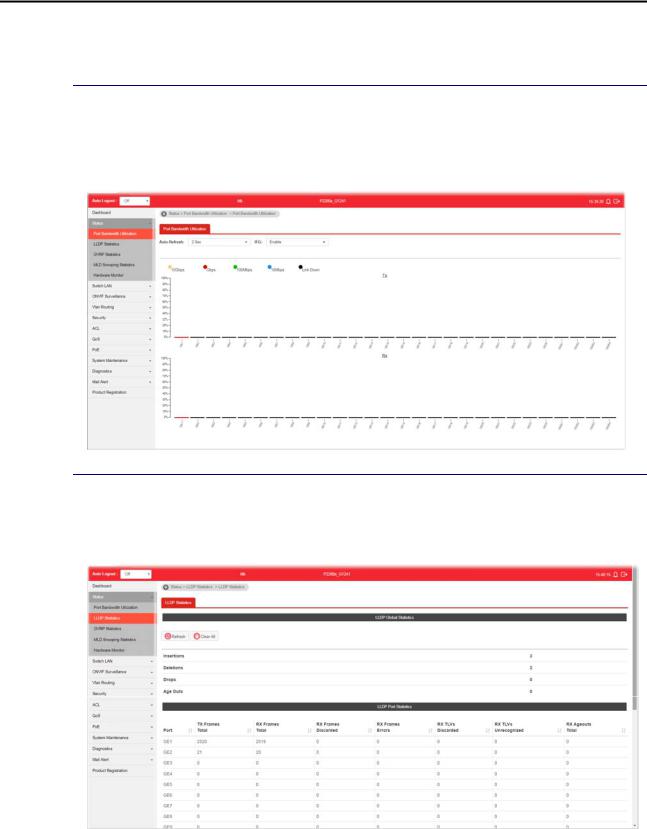
I-5-2 LLDP Statistics
This page offers the statistics of LLDP packets (in, out and error) of each port (GE1 to GE24, 10GE1 to 10GE4).
VigorSwitch P2280x User’s Guide |
17 |

I-5-3 GVRP Statistics
GVRP (Generic Attribute Registration Protocol) is used automatically for exchanging information for VLAN membership between switches. This page counts the GVRP information received on each port.
I-5-4 MLD Snooping Statistics
This page counts the MLD messages received or transmitted on the network.
18 |
VigorSwitch P2280x User’s Guide |

I-5-5 Hardware Monitor
This page displays the temperature change and voltage of VigorSwitch.
VigorSwitch P2280x User’s Guide |
19 |
This page is left blank.
20 |
VigorSwitch P2280x User’s Guide |
Loading...