

Page 1
119177-037 Rev. A 08/05/09
ENGLISH
TOOLS REQUIRED:
Drill (3/32” Drill Bit), Wire Crimpers,
Philips Head Screwdriver, Test-probe
NOTE: Steps 4 through 10
Some kits will require a wiring kit for installation
that may be sold separately.
1. CAUTION
Determine if the tow vehicle has a 2 wire
or 3 wire system.
2 WIRE SYSTEM
a) Same bulb for stop and turn signals
NOTE
Some vehicles have a separate bulb for stop signal
but also have a combination bulb for stop and turn
(such as 1992-95 Ford Taurus sedans). These
cars should be wired as 2 wire systems, using the
wires going to the common bulbs.
b) Attach the crimp on spade terminal provided
to the red “stop” wire and ground it along
with the white wire (mounting step 3).
3 WIRE SYSTEM
a) Amber turn signals.
b) Separate bulbs for stop and turn signals
(both red).
2. Determine a suitable location for mounting the
circuit protected convertor in an out of the way
spot near the left tail light in the trunk or on the
frame rail, if mounted under the vehicle.
CAUTION
When mounting under the vehicle, always make
sure that the unit is in a protected area and can
not be damaged from road debris or objects
driven over.
The Convertor shall also be mounted so that
the wiring is directed downward. If it is impossible
to direct downward, wiring should be directed
to the side.
3. Locate a suitable grounding point near the conver-
tor such as an existing ground stud or drill a 3/32”
hole and secure the white wire using the eyelet
and screw provided. (Do not drill into vehicle floor
or bed.) Clean dirt and rustproofing from area.
CAUTION
Verify what is behind any surface prior to drilling
to avoid damage to the vehicle and/or personal
injury. Do not drill into any exposed surfaces.
4. Disconnect and isolate the vehicle’s Negative (-)
battery terminal.
CAUTION
Read and follow all warnings and cautions
printed on the tow vehicle’s battery.
5. Using ring terminal (3/8” for top terminal or
1/2” for side terminal), attach an in-line fuse
holder (with fuse removed) to the Positive (+)
terminal of the battery.
NOTE
Cut the in-line fuse holder loop wiring.
6. Attach the 12 gauge wire to the fuse holder
with yellow butt connector.
7. Route 12 gauge (or larger gauge) wire from the
fuse holder to the convertor passing under or
through the vehicle.
CAUTION
When passing the wire through sheet metal
always go through an existing grommet, add a
grommet or use silicone rubber to insulate the
wire from the hole.
8. Attach the black 12 ga. wire to the red wire
from the T-Connector black box with the supplied
yellow butt connector.
Reconnect the tow vehicle’s Negative (-)
battery cable.
WARNING
Read and follow all warnings and cautions
printed on the tow vehicle’s battery.
9. When using a circuit tester, carefully probe
one wire at a time. Determine each of the vehicle
functions as shown in the illustration.
CAUTION
Do not probe across two wires or across wire
and vehicle structure.
10. Attach the trailer wiring to the vehicle as
shown in the illustration using wire splices.
WARNING
When splicing use appropriate gauge
wire splices.
11. Install the 20-amp fuse into the fuse holder.
TESTING PROCEDURE
With the ground wire connected and all of the
other circuits attached, attach the ground lead of
a circuit tester to the exposed ground terminal of
the 5-Flat end. Activate the tow vehicle’s left turn,
right turn, tail, backup and stop lights one at a
time. Probe the four receptacles of the 5-Flat
end to confirm proper functions.
12. Secure all loose wires with cable ties.
WARNING
Overloading circuit can cause fires. DO NOT
exceed lower of towing manufacturer rating or:
• Max stop/turn/backup light: 2 per side
(4.2 amps)
• Max. tail lights: (7.5 amps)
Read vehicle’s owners manual & instruction
sheet for additional information.
Installation Instructions
Directives de Montage
Instrucciones de Instalación
Circuit Protected Convertor
Convertisseur Protégé
Conversor de Circuitos Protegidos
READ THIS FIRST:
Read and follow all vehicle warnings and installation
instructions before beginning installation. Wear safety
glasses and use all safety precautions during installation.
LISEZ CECI EN PREMIER:
Lire et observer toutes les consignes de sécurité et les
instructions avant de commencer l’installation. Durant
l’installation, veiller à toujours porter des lunettes de
protection et respecter les mesures de sécurité.
LEA ESTO PRIMERO:
Lea y siga todas las advertencias e instrucciones de instalación
del vehículo antes de empezar la instalación. Use gafas
de seguridad y todas las precauciones de seguridad durante
la instalación.
PAGE 1 OF 3
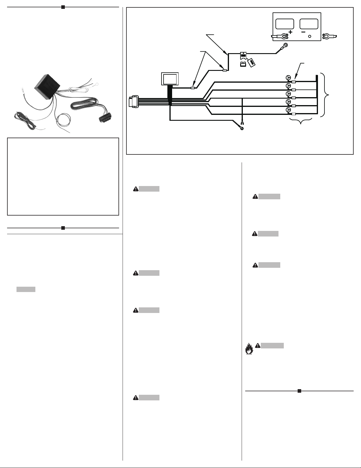
THIS TRAILER LIGHT POWER SUPPLY IS FOR
USE ON 12 VOLT NEGATIVE GROUND SYSTEMS ONLY
SECURE WIRE AFTER
INSTALLATION USING CABLE TIES
YELLOW BUTT CONNECTOR
TRAILER CONNECTOR
BATTERY RED
WHITE WIRE
GROUND SECURELY TO TOW VEHICLE
CHASSIS OR EXISTING GROUND STUD
USE 12 GA OR LARGER WIRE
12 VOLT BATTERY OF TOW VEHICLE
IN-LINE FUSE HOLDER
AND FUSE
INSTALL FUSE AFTER ALL
OTHER STEPS ARE COMPLETED
BROWN WIRE
YELLOW WIRE
RED WIRE
GREEN WIRE
BLUE WIRE
SEE WIRING STEP 1
2 WIRE SYSTEM:
CRIMP SPADE TERMINAL TO RED
WIRE AND ATTACH TO GROUND SCREW
3 WIRE SYSTEM:
ATTACH RED WIRE TO TOW VEHICLES
BRAKE LIGHT CIRCUIT
DISCONNECT NEGATIVE (-) CABLE
BEFORE WIRING POWER SUPPLY
USE BLUE WIRE TAPS 4 OR 5 PLACES
TAIL LIGHT
LEFT TURN
STOP
RIGHT TURN
BACKUP
TOW VEHICLE'S
TAIL LIGHTS
AND HARNESS
Page 2
CE BOÎTIER D’ALIMENTATION POUR LES LUMIÈRES
FRANÇAIS
OUTILS REQUIS:
Perceuse (mèche de 3/32 po),
Sertisseurs, Tournevis à pointe
cruciforme, Sonde de vérification
REMARQUE: étapes 4 et 10
Certains ensembles demandent pour l’installation
un nécessaire de filage vendu séparément.
1. ATTENTION
Déterminez si le véhicule remorqueur a
un système à 2 ou à 3 fils
Système à 2 fils
a) Même ampoule pour les signaux d’arrêt
et les clignotants
REMARQUE
Certains véhicules sont dotés d’une ampoule
distincte pour le signal d’arrêt mais ont aussi
une ampoule combinée pour l’arrêt et la direction
(par exemple la Ford Taurus berline 1992-95).
Ces véhicules devraient êtres munis de
systèmes à 2 fils, utilisant les fils allant
aux ampoules communes.
b) Fixez la cosse fournie au fil rouge d’arrêt
et branchez-le avec le fil blanc (étape 3).
Système à 3 fils
a) Signaux de virage ambrés.
b) Ampoules distinctes pour les signaux d’arrêt
et de virage (les deux sont rouges).
2. Déterminez un emplacement convenable (où il
ne nuira pas, isolé) pour monter le convertisseur
protégé: près du feux arrière gauche, dans le coffre
ou sur le châssis à gauche s’il est installé sous
le véhicule.
ATTENTION
Lors d’un montage sous le véhicule, veiller à
toujours placer l’unité dans un endroit protégé
où elle ne pourra être endommagée par des débris
routiers ou des objets percutés en roulant.
Le convertisseur doit aussi être monté de façon
que le câblage soit dirigé vers le bas. S’il est
impossible de le diriger vers le bas, le câblage
doit être dirigé vers le côté.
3. Repérer un endroit approprié (p.ex. borne de
masse) à proximité du convertisseur pour effectuer
la mise à la masse, ou percer un trou de 3/32 po et
fixer le fil blanc à l’aide de l’oeillet et de la vis fournis. (Ne pas percer le plancher ou la plateforme du
véhicule.) Nettoyer la surface pour y enlever toute
trace de saleté ou de traitement antirouille.
ATTENTION
Avant de percer, vérifier ce qui se trouve sous
la surface pour prévenir tout dommage au véhicule
ou toute lésion corporelle. Ne pas percer de
surfaces exposées.
4. Débrancher et isoler la borne négative (-) de la
batterie du véhicule.
ATTENTION
Lire et observer tous les avertissements et
consignes de sécurité qui sont imprimés sur
la batterie du véhicule de remorquage.
5. En utilisant l’oeillet (3/8” pour le terminal du
haut ou 1/2” pour le terminal du côté), fixez le
porteur de fusible (avec la fusible enlevé) au
terminal positif (+) de la batterie.
REMARQUE
Coupez le fil en cercle du porte-fusible.
6. Fixez le fil de calibre 12 au porteur de fusible
avec le manchon connecteur jaune.
7. Acheminer le fil de calibre 12 (un calibre supérieur)
depuis le porte-fusible jusqu’au convertisseur en
passant sous ou à travers le véhicule.
ATTENTION
Si vous passez le fil au travers du métal, passez
toujours au travers d’un passe-fil déjà en place,
ajoutez un passe-fil ou utilisez du caoutchouc
silicone pour isoler le fil du rebord du trou.
8. Connecter le fil noir de calibre 12 et le fil rouge
provenant de la boîte noire du connecteur en T
à l’aide du connecteur d’about jaune fourni.
Rebranchez le câble négatif (-) de la batterie
du véhicule remorqueur.
AVERTISSEMENT
Lire et observer tous les avertissements et
consignes de sécurité qui sont imprimés sur
la batterie du véhicule de remorquage.
9. Quand vous utilisez un vérificateur de circuit,
vérifiez soigneusement un fil à la fois. Déterminer
chaque fonction du véhicule tel qu’indiqué
sur l’illustration.
ATTENTION
Ne vérifiez pas en même temps deux fils ou un
fil et la structure du véhicule.
10. Fixer le câblage de la remorque au véhicule à
l’aide de jonctions de fils comme illustré.
AVERTISSEMENT
Utiliser des épissures dont le calibre est adéquat.
11. Installer un fusible de 20 A dans le porte-fusible.
PROCÉDURE D’ESSAI
Le fil de masse raccordé et les autres circuits
branchés, connectez le fil de masse d’un
vérificateur de circuit à la borne exposée de
la fiche plate à 5 conducteurs. Activer les feux
de direction gauche et droit, arrière, de recul et
d’arrêt, un à la fois. Vérifiez le fonctionnement
des quatre connecteurs femelles de la fiche
plate à 5 conducteurs.
12. Fixer tous les fils lâches à l’aide d’attaches
de câble.
AVERTISSEMENT
Un circuit surchargé peut occasionner des
incendies. NE DÉPASSEZ JAMAIS la valeur
la plus basse indiquée par le fabricant de
remorquage, ou:
• Nbre max. feux arrêt/direction/recul: 2 par côté
(4,2 ampères)
• Max. lumières arrières: (7,5 amps)
Consultez le manuel du propriétaire et la
feuille d’instructions du véhicule pour de
plus amples informations.
PAGE 2 OF 3
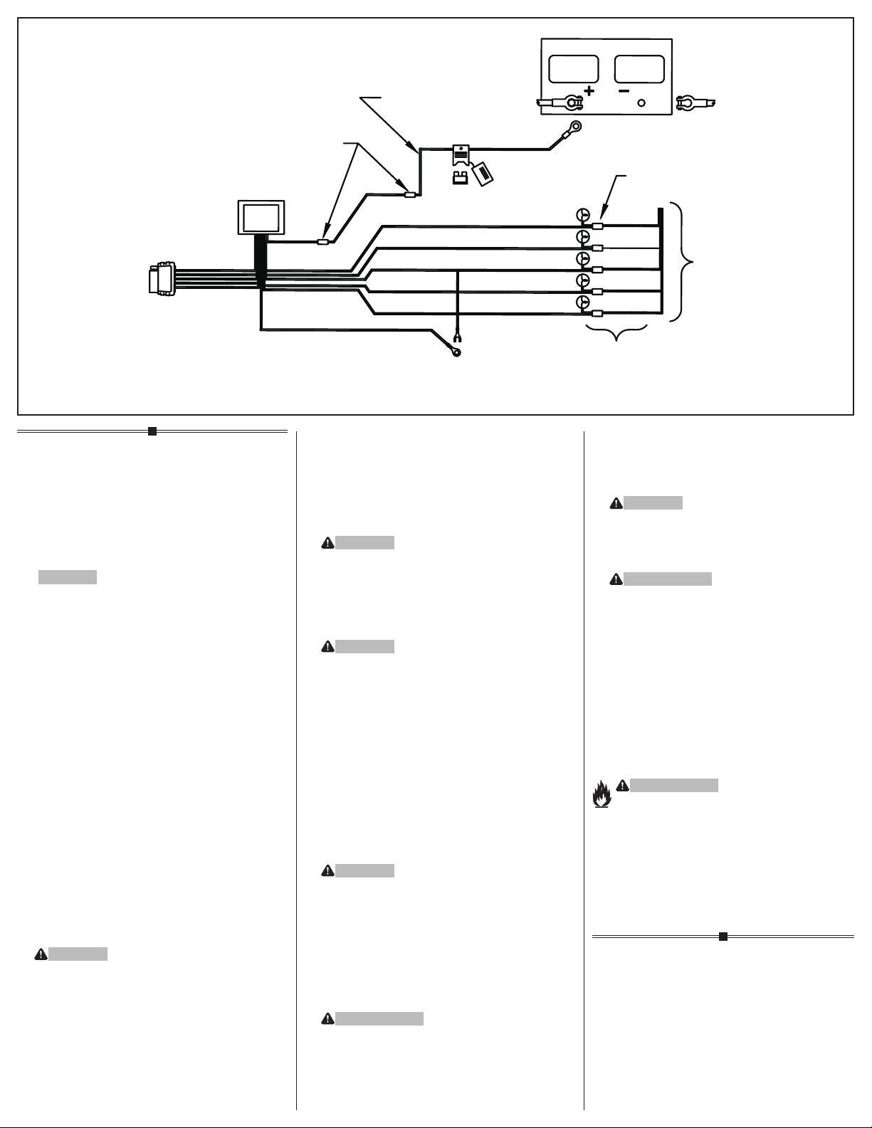
DE REMORQUE EST POUR UTILISATION SUR UN SYSTÈME
DE MISE À TERRE 12 VOLTS NÉGATIFS SEULEMENT
SUITE¸ A L'INSTALLATION, SECURISEZ LES
FILS EN UTILISANT LES COLLIERS DE SERRAGE
MANCHON CONNECTEUR JAUNE
CONN
ECTEUR DE
LA REMORQUE
BATTERIE
ROUGE
FIL BLANC
FIXEZ LA MI
AU CHÂSSIS DU VÉHICULE REMORQUEUR
UTILISEZ UN FIL DE CALIBRE 12,
OU PLUS GROS
S
E À TERRE SÉCURITAIREMENT
PORTE-FUSIBLE ET FUSIBLE
INSTALLEZ LA FUSIBLE APRÈS
QUE TOUS LES AUTRES ÉTAPES
SOIENT TERMINÉS
FIL BRUN
FIL JAUNE
FIL ROUGE
FIL VERT
FIL BLEU
BATTERIE DE 12 VOLTS DU VÉHICULE REMORQUEUR
DÉBRANCHEZ LE CÂBLE NÉGATIF (-) AVANT DE BRANCHER
LE BOÎTIER D'ALIMENTATION ÉLECTRIQUE
UTILISEZ LES CONNECTEURS
VOLANTS BLEUS À 4 OU 5 ENDROITS
FEUX ARRIERE
CLIGNOTANT
GAUCHE
ARRÊT
CLIGNOTANT
DROIT
FEU DE MARCHE
ARRIÈRE
VOIR LE FILAGE DE L’ÉTAPE 1
SYSTÈME À DEUX FILS
SERREZ LA COSSE AU FIL ROUGE ET FIXEZ¸ À LA VIS D
SYSTÈME À TROIS FILS
ATTACHEZ LE CÂBLE ROUGE AU
CIRCUIT DE LUMI
ÈRES DE FREINS DU VÉHICULE
FEU
X ARRIERES ET HARNAIS
DU VÉHI
CULE REMORQ
E MISE À TERRE
UEUR
Page 3
ESTA FUENTE DE PODER PARA LUCES
ESPAÑOL
HERRAMIENTAS NECESSARIAS:
Taladro (broca de 3/32”), Plegadores de cable,
Destornillador de estrella, Terminal de prueba
NOTA: pasos 4 a 10
Algunos kits requieren un kit de cables para instalación el cual se vende por separado.
1. ATENCIÓN
Determine si el vehículo de remolque tiene un
sistema de cableado de 2 o 3 cables.
Sistema de 2 cables
a) Usa el mismo bombillo para las direccionales
y la luz de freno.
NOTA
Algunos vehículos tienen una bombilla separada
para la luz de freno pero también tienen una bombilla combinada para freno y giro (como el Sedán
1992-95 Ford Taurus). Estos vehículos deben ser
conectados como sistemas de 2 cables, usando
los cables que van a los bombillos comunes.
b) Una el terminal plegable de pala que se provee a
el cable rojo marcado “stop” (freno)y conéctelos
a tierra junto con el cable blanco (Paso 3).
Sistema de 3 cables
a) Luces direccionales de color ámbar
b) Bombillos separados para freno y direccionales
(ambos rojos).
2. Determine un lugar apropiado para montar el protector de circuito de rendimiento normal, escoja un
lugar seguro cerca de las luces traseras izquierdas
en el baúl o en el riel izquierdo de la estructura, si
decide montarlo en la parte de afuera.
ATENCIÓN
Al instalar debajo del vehículo, siempre verifique
que la unidad esté en un área protegida y que no
se dañe con los desechos u objetos de la carretera
sobre los cuales se maneje.
El convertidor también se instalará de manera que
los cables se dirijan hacia abajo. Si es imposible
dirigirlos hacia abajo, se deben dirigir hacia el lado.
3. Encuentre un punto adecuado de conexión a tierra
cerca del convertidor como es un perno de tierra
existente o perfore un orificio de 3/32” y asegure
el cable blanco usando el ojete o tornillo que
se suministran. (No perfore en el piso o base
del vehículo). Limpie la suciedad y el anticorrosivo
del área.
ATENCIÓN
Revise qué hay detrás de cualquier superficie
antes de perforar para evitar daños al vehículo
y/o lesiones personales. No perfore ninguna
superficie expuesta.
4. Desconecte y aisle la terminal negativa (-) de la
batería del vehículo.
ATENCIÓN
Lea y siga todas las advertencias y precauciones
impresas en la batería del vehículo de remolque.
5. Usando el terminal de anillo (3/8”/9,53 mm para
el terminal de arriba o 1/2”/12,7 mm para el
terminal lateral), Una el sostenedor de fusible
en serie (con el fusible removido) al terminal
positivo (+) de la batería.
NOTA
Corte el cableado del sostenedor de fusible
en serie.
6. Una el cable de calibre 12 al sostenedor
de fusible usando el conector doble amarillo.
7. Dirija un cable calibre 12 (o calibre superior)
desde el retenedor de fusibles hasta el convertidor
pasando debajo o a través del vehículo.
ATENCIÓN
Cuando pase el cable a través de una lámina
metálica, páselo a través de un orificio blindado
ya existente o haga un nuevo agujero y use silicio
para aislar el cable del agujero.
8. Una el cable negro calibre 12 con el cable rojo
desde la caja conectora negra en T con el conector
de culata amarilla que se suministra.
Reconecte el terminal negativo (-) de la batería
del vehículo de remolque.
ADVERTENCIA
Lea y siga todas las advertencias y precauciones
impresas en la batería del vehículo de remolque.
9. Cuando use un verificador de circuitos, con
cuidado pruebe un cable a la vez. Determine
cada una de las funciones del vehículo como
se muestra en la ilustración.
ATENCIÓN
No pruebe entre dos cables o entre un cable
y la estructura del vehículo.
10. Instale los cables del remolque en el vehículo
como se muestra en la ilustración usando
empalmes de cables.
ADVERTENCIA
Al hacer empalmes use empalmes de cable
de calibre apropiado.
11. Instale el fusible de 20 amperios en el portador
de fusibles.
PROCEDIMIENTO DE PRUEBA
Con el cable a tierra conectado y todos los
otros circuitos igualmente conectados, coloque
la sonda a tierra de un probador de circuitos en
el terminal a tierra del extremo del 5-plano.
Active una por una la luces de giro a la izquierda,
giro a la derecha, traseras, reversa y de freno
del vehículo de remolque. Pruebe los cuatro
receptáculos del enchufe 5-plano para confirmar
las funciones apropiadas.
12. Asegure todos los alambres sueltos con amarres
de cables.
ADVERTENCIA
La sobrecarga del circuito puede ocasionar
incendios. NO exceda la calificación de remolque
más baja indicada por el fabricante o:
• Luz de freno/giro/reversa: 2 por lado
(4.2 amperios)
• Máx. luz trasera: (7.5 amperios)
Lea el manual del propietario y la hoja de instrucciones del vehículo para información adicional.
© 2009 Cequent Performance Products, Inc.PAGE 3 OF 3
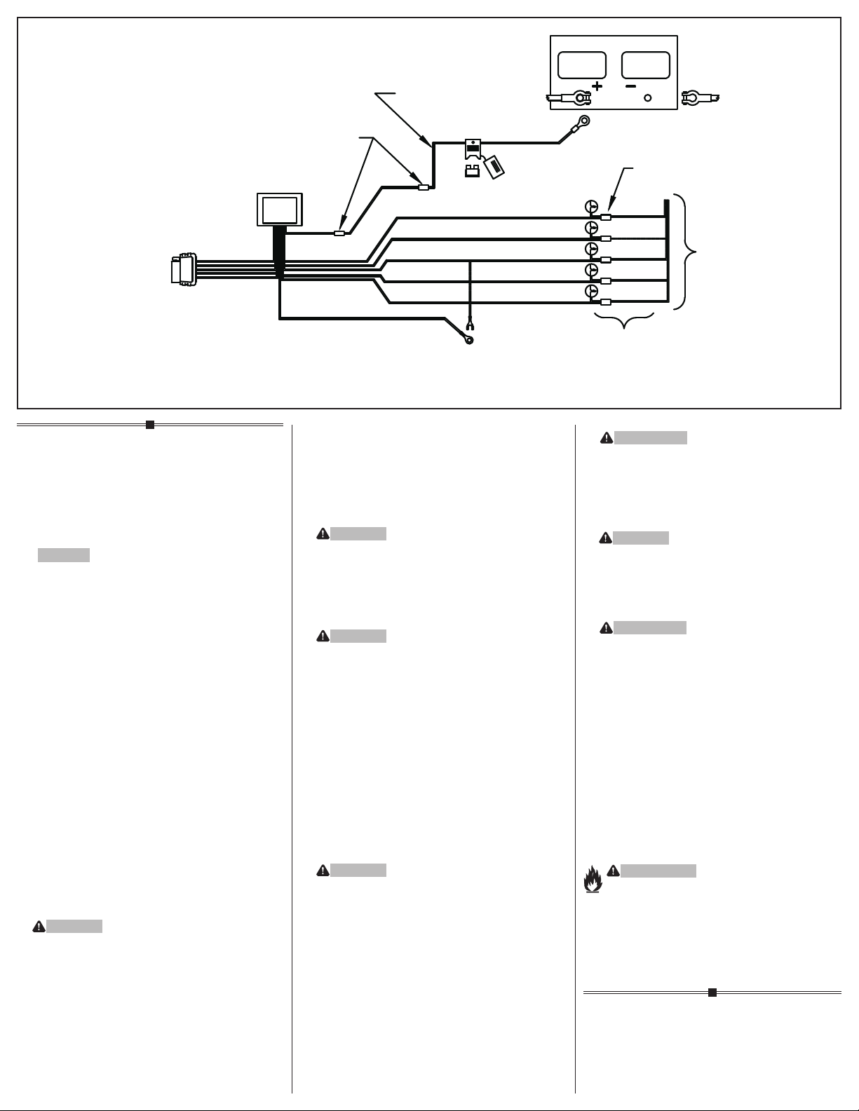
DE REMOLQUE DEBE SER USADA SOLAMENTE
EN SISTEMAS CON TIERRA NEGATIVA DE 12 VOLTIOS
BATERÍA DE 12 VOLTIOS DEL VEHÍCULO DE REMOLQUE
ASEGURE EL CABLE DESPUÉS DE LA INSTALACIÓN
USANDO LAS BANDAS DE AMARRE QUE
CONECTOR
DE REMOLQUE
USE CABLE DE CALIBRE 12 O MÁS GRANDE
SOSTENEDOR DE FUSIBLE
CONECTOR DOBLE AMARILLO
BATERIA ROJO
CABLE BLANCO
CONECTE FIRMENENTE (A TIERRA)
AL CHASIS DEL VEHICULO REMOLCADOR
EN SERIE Y FUSIBLE
INSTALE EL FUSIBLE DESPUÉ S
DE QUE TODOS LOS OTROS PASOS
HAYAN SIDO COMPLETADOS
CABLE MARRONÓ
CABLE AMARILLO
CABLE ROJO
CABLE VERDE
CABLE AZUL
DESCONECTE EL CABLE NEGATIVO (-)
ÁNTES DE CONECTAR LA FUENTE DE PODER
USE LOS CONECTORES A CORRIENTE
AZULES 4 O 5 LUGARES
LUCES
TRASERAS
DIRECCIONAL
IZQUIERDA
FRENO
DIRECCIONAL
DERECHA
LÁMPARA DE
RETROCESO
VEA EL PASO DE CABLEADO 1
SISTEMA DE 2 CABLES
PLIEGUE EL TERMINAL DE PALA JUNTO CON
EL CABLE ROJO Y ÚNALOS AL TORNILLO A TIERRA
SISTEMA DE 3 CABLES
UNA EL CABLE ROJO AL CIRCUITO DE
LAS LUCES DE FRENO DEL VEHÍCULO
LUCES TRASERAS Y CABLEADO
DEL VEHÍCULO DE REMOLQUE
 Loading...