

Equipment Required:
Fastener Kit: 4454F
Wrenches: 3/4, 15/16, 13mm
Drill Bits: 1/4”, some older models a 1/2”
Other Tools: Drill, Saber Saw
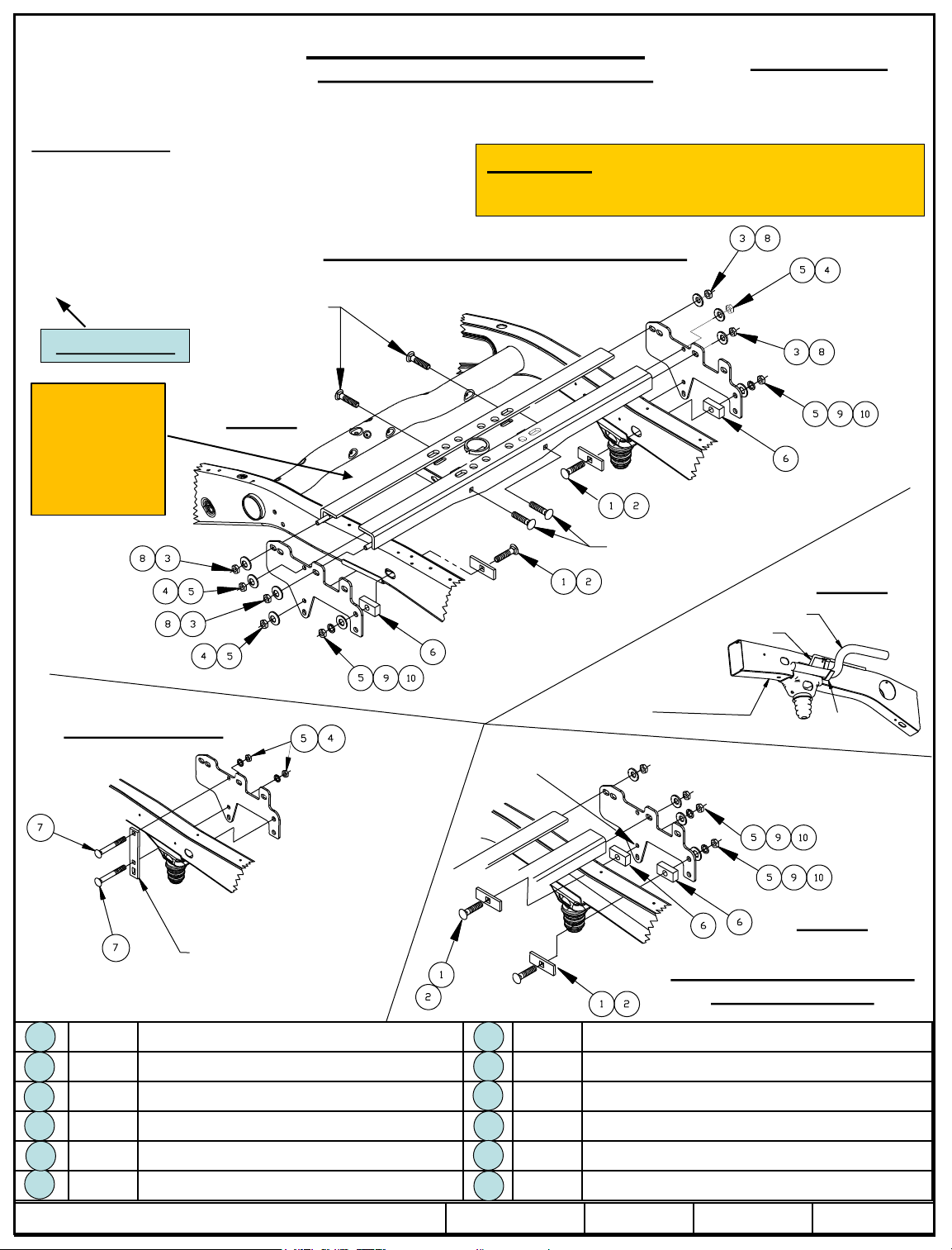
5/8” Fasteners
From Hitch Fastener Kit
Vehicle Forward
Wire harness is
close to the
front rail. If
required, add
additional
protection.
Figure 1
Installation Instructions
GOOSENECK MOUNTING KIT
Chevrolet/GMC 1500 Short & Long Beds
1500 HD, 2500LD Short Beds
WARNING: Under no circumstances do we recommend
exceeding the towing vehicle manufacturers recommended vehicle
towing capacity.
9465/9475 Hide-A-Goose Installation
Part Numbers:
4454
Clamp Installation
Clamp used on both sides of
vehicle – (Higher and lower
mounting location can be used,
depending height of frame)
5/8” fasteners from hitch
fastener Kit
Fishwire carriage
bolts and blocks
on closed frame
models
Driver’s Side Vehicle
Frame Rail
Use this hole in hitch bracket
as guide to drill frame
Figure 2
Electrical Cable
Brake Line
Cable
Bracket
Passenger’s side shown,
Driver’s side typical
Figure 3
Some older models including
1500HD & 2500LD
Qty. (4) Carriage Bolt, 1/2-13 x 2.25 GR5 Qty. (4) Carriage Bolt, 1/2 X-13 X 4.50 GR5
1
Qty. (4) Block, 1/4 X 1.00 X 3.00 Qty. (4) 5/8” Conical Toothed Washer
2
Qty. (4) 5/8-11 Hex nut Qty. (4) Lock Washer, 1/2
3
Qty. (4) ½” Conical Toothed Washer Qty. (4) Flat Washer, 1/2
4
Qty. (8) Hex Nut, 1/2 Qty. (4) Shims, 5/16 X 2.00 X 1.00
5
Qty. (4) Block, 5/8 X 1.00 X 2.00
6
© 2010, 2011 Cequent Performance Products – Printed in Mexico Sheet 1 of 8 4454N 1/23/2014 Rev. D
7
8
9
10
11
12
Qty. (2)
Fishwire – 1/2
Installation Instructions
Chevrolet/GMC 1500 Short & Long Beds
Part Numbers:
4454
1500HD, 2500LD Short Beds
NOTES:
This section of instructions refers to installing the 9465 or 9475 head only.
Always make sure the ball is fully locked before towing.
Keep the ball and ball sleeve well lubricated.
Periodically re-torque all the hitch fasteners.
Warning:
The tow vehicle manufacturers recommended towing capacities should UNDER NO CIRCUMSTANCES be exceeded.
Check for adequate clearance between the gooseneck trailer and the rear of the cab and the rear of the truck box before installing hitch.
All trucks have fuel lines, brake lines and electrical wiring located along the vehicle frame where the rail kit installs. Carefully examine the
location of fuel lines, brake lines and electrical wires before installation and be certain not to damage these when positioning the hitch
components. Be careful when drilling holes, cutting sheet metal and tightening fasteners as to not limit the integrity of these systems.
9465/9475 Hide-A-Goose Installation
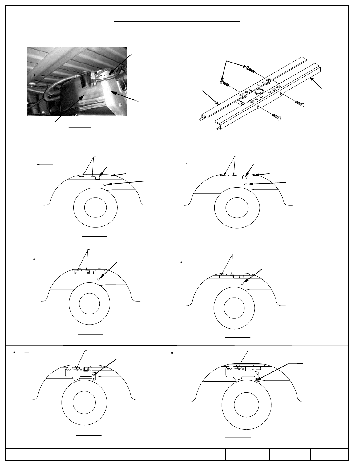
1. Figure 2 shows a cable bracket which holds a brake line to the inside of the frame rail. Loosen this bracket from the top of
the frame and move the brake line down about 1/2” so that it is not interfering with hitch cross members.
2. From underneath the passenger’s side of vehicle remove or cut out the section of the heat shield that is located between the
frame rails and the bed of the vehicle.
3. Cut the heat shield on the gas tank or bend the top edge down about 1” down to make room for the hitch (see Figure 3).
Check ball, hitch coupler, safety chains and other connections for proper operation every time you tow.
Hide-A-Goose Only – Drilled hole in bed location (see step 4).
Short Box – 44-3/4 inches
Long Box – 49-1/2 inches
4. When installing the 9465/9475 Hide-A-Goose hitch, a hole must be drilled in the bed of the truck. Mark and drill a 1/4” hole
44-3/4 inches (short box) / 49-1/2 inches (long box) from the rear of the bed and centered between the wheel wells. Using a
hole saw enlarge pilot hole to final diameter hole size. Refer to the 9465/9475 Hide-A-Goose hitch instruction sheet for hole
size.
5a. Placing Cross Members Between Bed And Frame, Method 1: Loosen The Truck Bed: Remove four truck bed bolts
(using 18mm socket) completely from the drivers side frame. The bolts are located on the bottom side of the frame. Loosen,
but do not remove, the four bolts holding the bed to the passenger side of the frame. Prop up the driver’s side of the truck bed
enough to make room for the cross members to fit between the bottom of the truck bed side flange and the top of the frame.
5b. Placing Cross Members Between Bed And Frame, Method 2: Notch the Side Flange: From the driver’s side wheel well,
notch the sheet metal flange as shown in Figure 5a for 6’ beds and Figure 5b for 8’ beds. After notching, the cut steel surfaces
should be touched up with paint to prevent rusting.
6. Slide the hitch cross members half way through the notches in the sheet metal flange and place 5/8 carriage bolts from the
9465/9475 fastener kit into the square holes on the vertical leg of the cross members, from underneath the vehicle. Slide the
hitch cross members above both vehicle frame rails and align hitch cross members as shown in Figure 6. Note: if the truck
bed has been loosened as in step 5a, the hitch can be loosely preassembled to the cross members, and the hitch and cross
members can be slid between the truck bed flange and the vehicle frame (see figure 4). The truck bed will need to be
propped up on the driver’s side about 3-1/2” to slide the hitch and cross members into position.
7. Loosely install the 9465/9475 Hide-A-Goose hitch if not done in the previous installation step. Refer to Hide-A-Goose Hitch
instruction sheet for installation.
8. Place 1/4 X 1.00 X 3.00 blocks and ½ carriage bolts through slots in the driver’s side and passenger’s side of vehicle frame
pointing outwards. Install the 5/8 X 1.00 X 2.00 block onto the carriage bolts. Install the hitch frame brackets by aligning the
rearward holes in the brackets with the carriage bolts and install the 1/2 flat washer, lock washers and hex nuts. Loosely install
the 5/8-11 hex nuts and conical toothed washers onto the threaded studs on the ends of the hitch cross members (see Figure 7).
9. Install the frame bracket clamp by placing the clamp to the inside of the frame rail, insert the 1/2-13 X 4.50 GR5 carriage bolts
through the square holes in the clamp and through the frame bracket with the threaded end pointing outwards. Install the
conical toothed washers and hex nuts. Some models require using hole in hitch bracket as guide to drill frame. See Figure 3.
10. After loosely installing the 9465/9475 Hide-A-Goose hitch and mounting kit, carefully align the hitch ball sleeve with the
opening cut in the truck bed. Torque all 5/8-11 GR5 fasteners on the brackets to 150 ft.-lb. (203 N-m) and 1/2-13 GR5
fasteners to 75 ft.-lb. (102 N-m). Use the following sequence: a) torque frame brackets to the frame of the vehicle, b) torque
cross members to the frame brackets, c) torque Hide-A-Goose hitch to cross members.
11. If vehicle bed was lifted to insert cross members, tighten bolts that attach the bed to the frame.
© 2010, 2011, 2014 Cequent Performance Products – Printed in Mexico Sheet 2 of 8 4454N 1/23/2014 Rev. D
Installation Instructions
Chevrolet/GMC 1500 Short & Long Beds
1500HD, 2500LD Short Beds
Trim or
bend heat
shield here
Forward cross member Rear
Heat
shield
5/8” carriage bolts
5/8” washer
5/8” nut
All hardware pictured is from
Hide-A-Goose Hitch fastener kit
Part Numbers:
4454
cross
member
Fuel tank
Forward
Figure 3
Rear of Gas Tank
Sections to be Notched
Vehicle
Forward
Figure 5a
Short Bed – Hide-A-Goose
Hitch Cross Members
Vehicle
Bed Hat Section
Sheet Metal Flange
Mounting Hole
Rearward
Mounting Hole
Rearward
Hitch preassembled to cross members
Sections to be Notched
Vehicle
Forward
Figure 5b
Long Bed – Hide-A-Goose
Hitch Cross Members
Vehicle
Forward
Figure 4
Bed Hat Section
Sheet Metal Flange
Rearward
Mounting Hole
Rearward
Mounting Hole
Figure 6a
Short Bed – Hide-A-Goose
Vehicle
Forward
Short Bed – Hide-A-Goose
© 2010, 2011, 2014 Cequent Performance Products – Printed in Mexico Sheet 3 of 8 4454N 1/23/2014 Rev. D
Hitch Frame Bracket
Rearward
Mounting Hole
Figure 7a
Long Bed – Hide-A-Goose
Vehicle
Forward
Figure 6b
Hitch Frame Bracket
Rearward
Mounting Hole
Figure 7b
Long Bed – Hide-A-Goose

Installation Instructions
GOOSENECK MOUNTING KIT
Chevrolet/GMC 1500 Short & Long Beds
1500HD, 2500LD Short Beds
This page was intentionally left blank.
Part Numbers:
4454
© 2010, 2011, 2014 Cequent Performance Products – Printed in Mexico Sheet 4 of 8 4454N 1/23/2014 Rev. D

Installation Instructions
GOOSENECK MOUNTING KIT
Chevrolet/GMC 1500 Short & Long Beds
1500HD, 2500LD Beds
Part Numbers:
4454
Equipment Required:
Fastener Kit: 4454F
Wrenches: 3/4, 15/16, 13mm
Drill Bits: 1/4”, some older models a 1/2”
Other Tools: Drill, Saber Saw
5/8” Fasteners
From Hitch Fastener Kit
Vehicle Forward
WARNING: Under no circumstances do we recommend
exceeding the towing vehicle manufacturers recommended vehicle
towing capacity.
6300/630044 or 8339 Gooseneck Hitch
Installation
Figure 1
Fishwire carriage bolts and
blocks on closed frame
models
Figure 2
Electrical Cable
Brake Line
Driver’s Side Vehicle
Frame Rail
Clamp Installation
Use this hole in hitch bracket
as guide to drill frame
Clamp used on both sides of
vehicle – (Higher and lower
mounting location can be used,
depending height of frame)
Qty. (4) Carriage Bolt, 1/2-13 x 2.25 GR5 Qty. (4) Carriage Bolt, 1/2 X-13 X 4.50 GR5
1
Qty. (4) Block, 1/4 X 1.00 X 3.00 Qty. (4) 5/8” Conical Toothed Washer
2
Qty. (4) 5/8-11 Hex nut Qty. (4) Lock Washer, 1/2
3
Qty. (4) ½” Conical Toothed Washer Qty. (4) Flat Washer, 1/2
4
Qty. (8) Hex Nut, 1/2 Qty. (4) Shims, 5/16 X 2.00 X 1.00
5
Qty. (4) Block, 5/8 X 1.00 X 2.00 Qty. (2) Fishwire – 1/2
6
7
8
9
10
11
12
Some older models including
Cable
Bracket
Passenger’s side shown,
Driver’s side typical
Figure 3
1500HD & 2500 LD
© 2010, 2011, 2014 Cequent Performance Products – Printed in Mexico Sheet 5 of 8 4454N 1/23/2014 Rev. D

Installation Instructions
Part Numbers:
Chevrolet/GMC 1500 Short & Long Beds
4454
1500HD, 2500LD Beds
NOTES:
This section of instructions refers to installing the 6300, 630044 or 8339 head only.
Always make sure the ball is fully locked before towing.
Keep the ball and ball pocket well lubricated.
Periodically re-torque all the hitch fasteners.
Check ball, hitch coupler, safety chains and other connections for proper operation every time you tow.
Warning:
The tow vehicle manufacturers recommended towing capacities should UNDER NO CIRCUMSTANCES be exceeded.
Check for adequate clearance between the gooseneck trailer and the rear of the cab and the rear of the truck box before installing hitch.
All trucks have fuel lines, brake lines and electrical wiring located along the vehicle frame where the rail kit installs. Carefully examine the
location of fuel lines, brake lines and electrical wires before installation and be certain not to damage these when positioning the hitch
components. Be careful when drilling holes, cutting sheet metal and tightening fasteners as to not limit the integrity of these systems.
6300/630044 Remove-A-Ball and 8339 Fold Down Gooseneck Installation
1. Figure 2 shows a cable bracket which holds a brake line to the inside of the frame rail. Loosen this bracket from the top of
the frame and move the brake line down about 1/2” so that it is not interfering with hitch cross members.
2. From underneath the passenger’s side of vehicle remove or cut out the section of the heat shield that is located between the
frame rails and the bed of the vehicle.
3a. Placing Cross Members Between Bed And Frame, Method 1: Loosen The Truck Bed: Remove four truck bed bolts
(using 18mm socket) completely from the drivers side frame. The bolts are located on the bottom side of the frame. Loosen,
but do not remove, the four bolts holding the bed to the passenger side of the frame. Prop up the driver’s side of the truck bed
enough to make room for the cross members to fit between the bottom of the truck bed side flange and the top of the frame.
3b. Placing Cross Members Between Bed And Frame, Method 2: Notch the Side Flange: From the driver’s side wheel well,
notch the sheet metal flange as shown in Figure 4a for 6’ beds and Figure 4b for 8’ beds. After notching, the cut steel surfaces
should be touched up with paint to prevent rusting.
4. Slide the hitch cross members above both vehicle frame rails and align hitch cross members as shown in Figure 5.
5. Place 1/4 X 1.00 X 3.00 blocks and 1/2-13 X 2.25 carriage bolts through slots in the driver’s side and passenger’s side of
vehicle frame pointing outwards and install the hitch frame brackets by aligning the rearward holes in the brackets with the
fasteners. Loosely install the 5/8-11 hex nuts and conical toothed washers onto the threaded studs on the ends of the hitch cross
members (see Figure 6).
6. Install the frame bracket clamp by placing the clamp to the inside of the frame rail, insert the 1/2-13 X 4.50 GR5 carriage bolts
through the square holes in the clamp and through the frame bracket with the threaded end pointing outwards. Install the ½
conical toothed washers and hex nuts. Some models require using hole in hitch bracket as guide to drill frame, see Figure 3.
7. With the rearward cross member and side brackets in position, torque the 5/8-11 GR5 fasteners that attach the brackets to the
rearward cross member to 150 ft.-lb (203 N-m) and the 1/2-13 GR5 fasteners that attach the brackets to the frame to 75 ft-lb.
(102 N-m). The forward cross member should be left loose until step 17. If vehicle bed was lifted to insert cross member,
tighten bolts that attach the bed to the frame.
WARNING The fuel tank and/or other vehicle components are located below some of the holes. A wood or metal shield must be
placed between the frame and the fuel tank to prevent puncturing the fuel tank when the drill breaks through the bed.
8. For 6300/630044 & 8339 use the center of the outer slots in the rearward hitch cross member as a template to drill 5/8”
diameter holes through the truck bed as shown in Figure 3. Not all holes can be drilled from under the vehicle, but will be
done later from inside the bed.
6300 / 630044 / 8339 Hole
Locations
© 2010, 2011, 2014 Cequent Performance Products – Printed in Mexico Sheet 6 of 8 4454N 1/23/2014 Rev.D
Use center of slots to
drill 5/8” holes
Figure 3
Forward cross
member
Rearward cross
member

Installation Instructions
Part Numbers:
Chevrolet/GMC 1500 Short & Long Beds
4454
1500HD, 2500LD Beds
9. Align the holes on the template (provided with the gooseneck hitch) with the holes previously drilled through the bed. Be sure
that the template is properly oriented toward the front of the vehicle. Center punch the holes that will be used to cut the
opening in the bed. If the vehicle is equipped with a bed liner, a section of the bed liner must be cut away so that the
gooseneck platform can contact the bed corrugations.
Durable and reusable stainless steel templates are also
available. A time saver for cutting bed liner and bed.
Template p/n 6467 for use with 6300/630044 head
Template p/n 6425 for use with 8339 head
10. Drill 1/4” pilot holes (size will depend on width of blade in saber saw). Cut out the truck bed and the bed hat section on short
bed models from underneath the bed of the vehicle and file edges as needed.
11. Install the hitch into the opening.
12. Use the hitch as a guide to drill the 5/8” diameter holes for the forward cross member and the U-Bolt holes.
11
Template p/n 5978 for use with 6300/630044 head
Template p/n 114234 for use with 8339 head
1
5/8” X 2.50 GR5 Carriage Bolt Lockwasher
Hex Nut
4 Places
13. Before installing the 5/8” carriage bolts through the hitch, the U-block shims (Part Number 5979) must be placed between the
hitch and the bed and between the cross members and the bottom of the bed. These shims are necessary to prevent the bed
corrugations from collapsing when the bolts are tightened.
14. Align the forward cross member with the 5/8 diameter drilled holes.
15. Install the 5/8 X 2.50 GR5 carriage bolts through the hitch, shims and cross members. Secure with lock washers and nuts.
Torque nuts to 150 ft.-lb. (203 N-m).
16. Install the (2) U-Bolts through the hitch and from under the vehicle install the large flat washer over the U-Bolt followed by a
spring, another large flat washer and secure with a thin 5/8” jam nut. Repeat for the other legs of the U-Bolts. The 5/8” jam
nuts are tightened until (3) threads are visible past the bottom of the jam nut.
17. Torque the 5/8 hex nuts, lock washers, and flat washers that attach the brackets to the forward cross member to 150 ft.-lb. (203
N-m).
© 2010, 2011, 2014 Cequent Performance Products – Printed in Mexico
Sheet 7 of 8 4454N 1/23/2014 Rev. D

Installation Instructions
Part Numbers:
Chevrolet/GMC 1500 Short & Long Beds
4454
1500HD, 2500LD Beds
Sections to be Notched or Bent
Vehicle
Forward
Bed Hat Section
Sheet Metal Flange
Rearward Mounting
Hole
Vehicle
Forward
Sections to be Notched or Bent
Sheet Metal Flange
Bed Hat Section
Rearward Mounting
Hole
Figure 4a
Short Bed
Remove-A-Ball/Fold Down Gooseneck
Hitch Cross Members
Vehicle
Forward
Rearward Mounting
Remove-A-Ball/Fold Down Gooseneck
Vehicle
Forward
Hole
Figure 4b
Long Bed
Hitch Cross Members
Rearward Mounting
Hole
Figure 5a
Short Bed
Remove-A-Ball/Fold Down Gooseneck
Vehicle
Forward
Figure 6a
Short Bed
Remove-A-Ball/Fold Down Gooseneck
© 2010, 2011, 2014 Cequent Performance Products – Printed in Mexico Sheet 8 of 8 4454N 1/23/2014 Rev. D
Hitch Frame Bracket
Rearward
Mounting Hole
Remove-A-Ball/Fold Down Gooseneck
Vehicle
Forward
Remove-A-Ball/Fold Down Gooseneck
Figure 5b
Long Bed
Hitch Frame Bracket
Rearward
Mounting Hole
Figure 6b
Long Bed
 Loading...