

Page 1
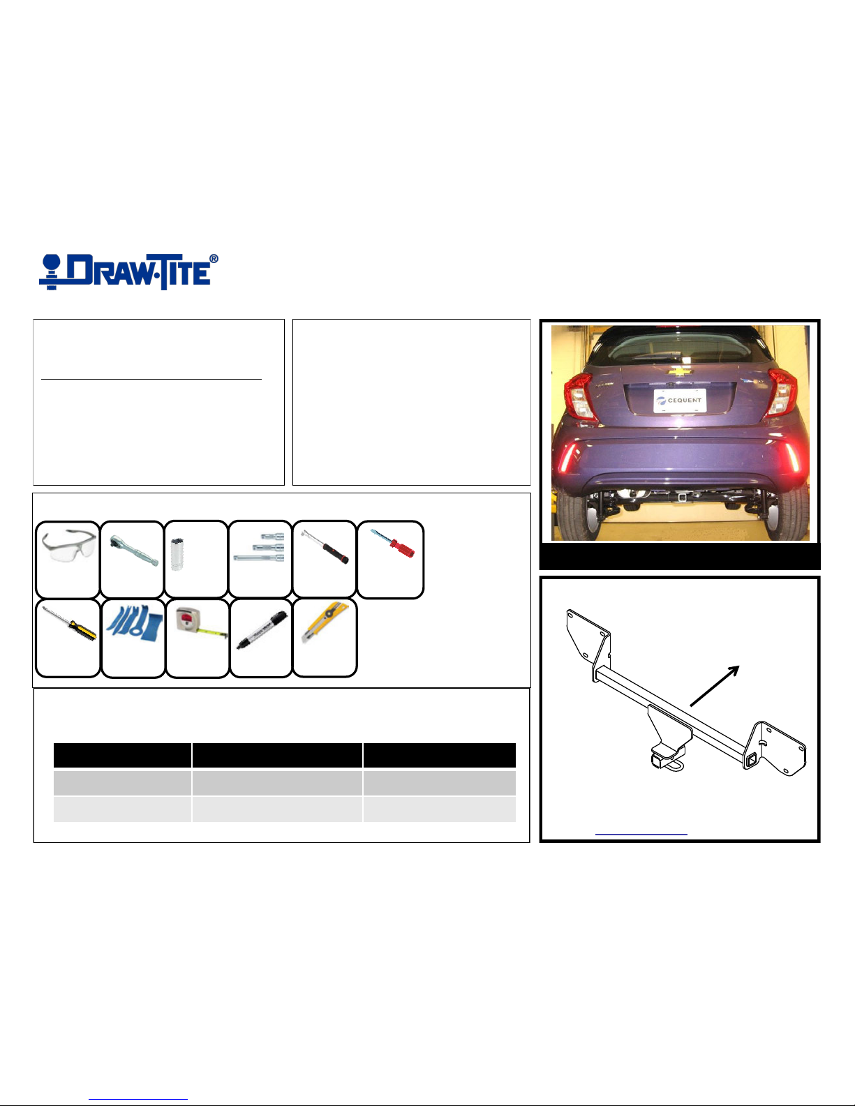
Applications:
Years Make Models
2016 -Current* Chevy Spark
Ratchet
Torque
Wrench
Safety
Glasses
Sockets
7 mm
13 mm
DO NOT EXCEED LOWER OF TOWING VEHICLE
MANUFACTURER’S RATING OR:
Hitch Type Max Gross Trailer Weight Max Tongue Weight
Weight Carrying 2000 lb. (908 kg) 200 lb. (90.8 kg)
Weight Distributing
X X
Representative Vehicle Photo
Installation Time: 45 min
The time listed above is the average time
for professional installers. If you do not
feel comfortable performing this
installation on your own or are in need of
assistance, please contact a professional
installer.
Trailer Hitch Illustration
Front of
Vehicle
6’’ Socket
Extension
Installation Instructions
PART NUMBERS: 24941, 77328, CQT24941
Equipment Required:
Phillips
Screwdriver
Tape
Measure
Flat
Head Screw
Driver
Plastic
Trim Tools
Utility
Knife
Marker
Page 2
Note: check hitch frequently, making sure all fasteners and ball are properly tightened. If hitch is removed, plug all holes in trunk pan or other body panels to prevent entry of water and exhaust fumes. A hitch or ball which
has been damaged should be removed and replaced. Observe safety precautions when working beneath a vehicle and wear eye protection. Do not cut access or attachment holes with a torch. This product complies with safety
specifications and requirements for connecting devices and towing systems of the state of New York, V.E.S.C. Regulation V-5 and SAE J684.
Installation Instructions
PART NUMBERS: 24941, 77328, CQT24941
Proper torque is needed to keep the hitch secure to the vehicle when towing.
Always wear SAFETY GLASSES
when installing hitch
1. Remove fascia
a.) using a 7 mm socket, remove (1) screw inside of rear wheel well, and (5) screws holding splash guard to fascia, both sides.
b.) using a flat head screw driver, remove (2) plastic retainers at the bottom center of Fascia.
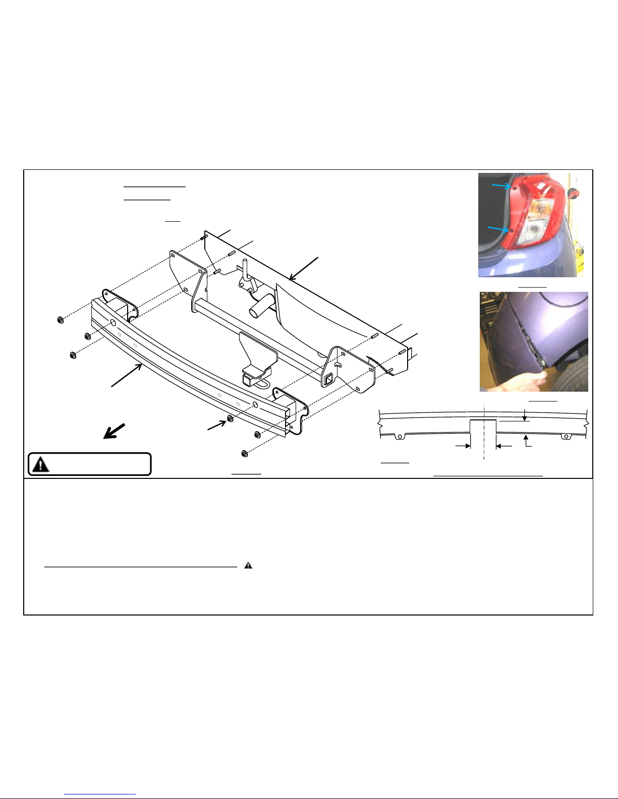
c.) using a Phillips head screw driver, remove (2) screws holding tail lights to vehicle, both sides. Gently pull taillights rearward. Unplug wiring harness or remove bulbs from taillight
housings. NOTE: Red wire is Top, Yellow wire is Center, and Blue wire is Bottom. See Figure 2.
d.) using a Phillips head screw driver, remove (2) screws holding fascia to vehicle, (1) per side.
e.) using a plastic trim panel tool, gently remove the plastic fascia starting at the wheel wells first. See Figure 3.
2. Remove bumper beam – using a 13mm socket with extension, remove (6) flange nuts attaching bumper beam to end panel. See Figure 1.
3. Hitch installation – raise hitch and bumper beam into position aligning holes with studs on the end panel. Sandwich the hitch between bumper beam and end panel. See Figure 1.
4. Reinstall fasteners - Loosely reinstall the existing (6) flange nuts onto studs in end panel, (3) per side.
5. Tighten all fasteners with torque wrench to 20 Lb.-Ft. (27 N*M)
6. Trim and reinstall fascia & splash guards – measure, mark, and trim fascia as shown in figure 4. Reinstall fascia and splash guards.
7. Reinstall taillights and wiring – reconnect the wiring and reinstall the taillights using the original (4) philips head screws, (2) per side.
Rear
Figure 1
(Sold separately)
Drawbar Kit: 3593
Drawbar must be
used in the RISE
position only
3-1/4”
2-1/4”
Bottom View of Bumper Fascia
Figure 4
Figure 2
Figure 3
Bumper end
panel
Bumper beam
Existing
M8-1.25 flange nuts
(6) Places
C
L
CENTERLINE OF BUMPER
Page 3

1a. Remove fascia
using a 7 mm socket, remove (1) screw inside of rear wheel well,
and (5) screws holding splash guard to fascia, both sides.
1c. Remove fascia
using a Phillips head screw driver, remove (2) screws holding
taillights to vehicle, both sides. Gently pull taillights rearward.
Unplug wiring harness or remove bulbs from taillight housings.
NOTE: Red wire is Top, Yellow wire is Center, and Blue wire is
Bottom.
1b. Remove fascia
using a flat head screw driver, remove (2) plastic retainers at the
bottom center of Fascia.
1d. Remove fascia
using a Phillips head screw driver, remove (2) screws holding fascia
to vehicle, (1) per side.
Page 4

1e. Remove fascia
using a plastic trim panel tool, gently remove the plastic fascia
starting at the wheel wells first.
3. Hitch installation – raise hitch and bumper beam into position
aligning holes with studs on the end panel. Sandwich the hitch
between bumper beam and end panel.
2. Remove bumper beam – using a 13mm socket with extension,
remove (6) flange nuts attaching bumper beam to end panel.
4. Reinstall fasteners - Loosely reinstall the existing (6) flange nuts
onto studs in end panel, (3) per side.
Page 5

5. Tighten all fasteners with torque wrench to
20 Lb.-Ft. (27 N*M)
6. Trim fascia – measure, mark, and trim fascia as shown
3-1/4”
2-1/4”
Bottom View of Bumper Fascia
Figure 4
CENTERLINE OF BUMPER
7. Reinstall taillights and wiring – reconnect the wiring and reinstall
the taillights using the original (4) phillips head screws, (2) per side.
Proper torque is needed to keep the hitch secure to the vehicle
when towing.
 Loading...