

Page 1
Catalog No. 8339
A
INSTALLATION INSTRUCTIONS
READ THOROUGHLY BEFORE BEGINNING
5
2
/16“ FOLDING BALL GOOSENECK HITCH
COVERED BY U.S. PATENT NOS. 5,738,363 & 5,893,575
Note: GM composite (NON METAL) bed will require Installation Kit #58209
IMPORTANT!
This product is intended to be used with Towing Products manufactured Rail Kits. If the Gooseneck Hitch
installation is made with Towing Products manufactured Rail Kits, the installation instructions for the
Gooseneck Hitch are included as part of the Towing Products Rail Kit installation instructions. Give this
installation instruction to vehicle owner after installation is complete.
General instructions for fabricated support structures.
IF TOWING PRODUCTS MANUFACTURED RAIL KITS ARE NOT USED, THIS PRODUCT BECOMES A
GENERAL APPLICATION PRODUCT. IT IS THE RESPONSIBILITY OF THE INSTALLER TO SELECT
STRUCTURALLY SAFE MATERIALS AND LOCATIONS FOR ATTACHMENT. INSTALLATION INFORMATION
FOLLOWS.
- MAXIMUM RATINGS -
DO NOT EXCEED LOWER OF TOWING VEHICLE MANUFACTURER'S RATINGS OR THOSE LISTED
BELOW:
25,000 LB GROSS TRAILER WEIGHT 6,250 LB VERTICAL LOAD
TOOLS REQUIRED:
Hand drill
Drill bits - 1/4”, 5/8”, 3/4”
Sockets and Wrenches - 9/16” & 15/16”
Center Punch
Torque Wrench
Saber Saw
Files - round and flat
Hammer
NOTE: CHECK HITCH FREQUENTLY, MAKING SURE ALL FASTENERS ARE PROPERLY TIGHTENED. A HITCH OR BALL WHICH HAS
BEEN DAMAGED SHOULD BE REMOVED AND REPLACED. OBSERVE SAFETY PRECAUTIONS WHEN WORKING BENEATH A VEHICLE
ND WEAR EYE PROTECTION. FOLLOW VEHICLE MANUFACTURER’S SPECIFICATIONS FOR MAXIMUM TRAILER WEIGHT. DO NOT
CUT ACCESS OR ATTACHMENT HOLES WITH A TORCH.
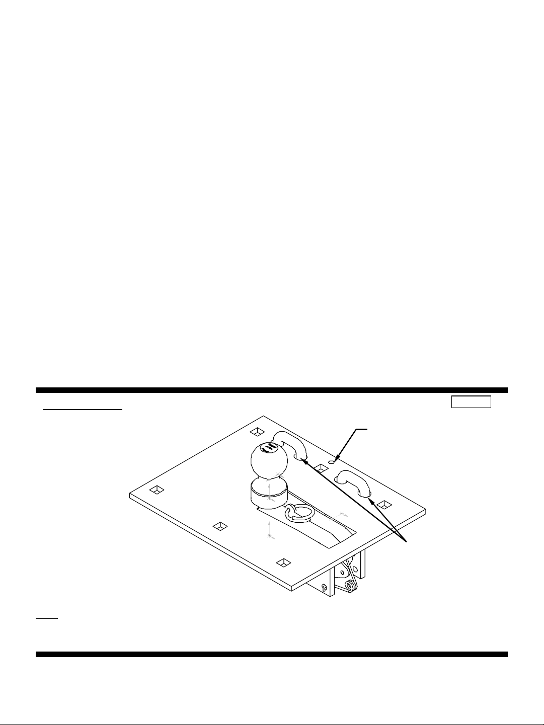
HOLE FOR BREAKAWAY
SWITCH CABLE ATTACHMENT.
(SCREW & WASHER PROVIDED)
SAFETY CHAIN ATTACHMENTS
U-BOLTS PROVIDED
Fig. 1
INSTRUCTION PART NO. N8339 1-15-07_C © 2002, 2007 CEQUENT TOWING PRODUCTS PRINTED IN U.S.A. PCN 9386
Page 2
PARTS LIST: PART BAG CONTENTS
DESCRIPTION
5/8-11 X 2.5 GRADE 5 CARRIAGE BOLTS 6
5/8-11 NUT 6
5/8 LOCKWASHER 6
5/8 U-BOLT ZINC PLATED 2
5” SPRING 4
BALL ASSEMBLY PART BAG
5/8-18 LOCKNUT 4
9/16 FLAT WASHER 8
3/8 FLAT WASHER 1
24-9 X 1” TAP SCREW 1
INSTRUCTION SHEET
Note: GM composite (NON METAL) bed will require Installation Kit #58209
INSTALLATION INSTRUCTIONS:
1. The following guidelines must be followed before installation begins:
- The hitch ball must be located along the truck’s fore/aft centerline.
- The hitch ball centerline must be located above and forward of the rear axle of the truck.
- Adequate clearance must be provided between the gooseneck trailer and the rear of the vehicle so that the gooseneck trailer does
not contact any part of the truck during turning.
- Adequate clearance must be provided between the forward corners of the gooseneck trailer and the cab of the truck.
- Determine that the ball position and under vehicle supports do not interfere with any vehicle crossmembers, brake lines, electrical
wiring, cables, fuel lines or vents.
2. With hitch ball center marked on the truck, lay template in the bed of the truck. Make sure that the template is oriented properly per
notes on the template. If truck is equipped with a bed liner a 14.5” x 12” section of the bed liner must be cut out so that the
gooseneck platform can contact the metal truck bed corrugations.
3. Center punch the holes that will be used to cut out the truck bed.
4. Drill 1/4” pilot holes (size will depend on the width of blade in saber saw).
5. Cut out truck bed. File the edges as needed.
6. Install platform into opening.
7. Use the installed platform as a guide to drill 5/8” diameter holes through the truck bed and/or under vehicle supports for the
carriage bolts and drill 3/4" diameter holes for U-bolts.
Before drilling, make sure the platform is oriented square to the truck centerline and does not interfere with
any vehicle crossmembers, brake lines, electrical wiring, cables, fuel lines or vents.
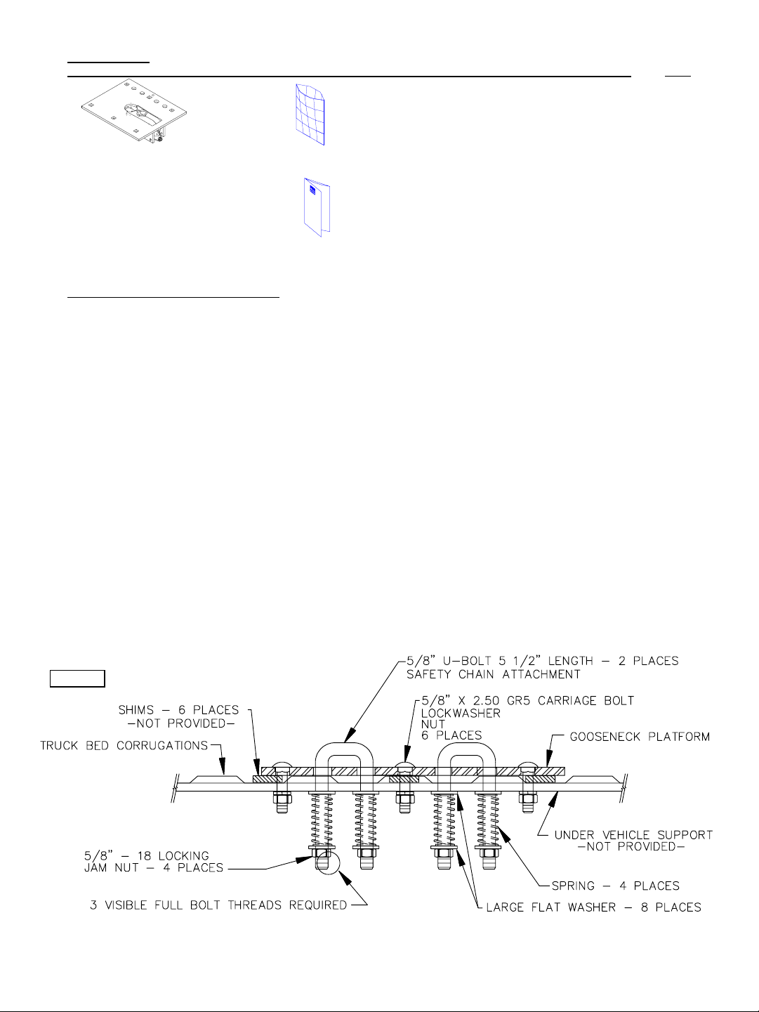
8. Before installing 5/8" carriage bolts through the platform, shims (not provided) must be placed between the platform and the bed
and between the under vehicle structure and the bottom of the bed. These shims are necessary to prevent the truck bed
corrugations from collapsing when the carriage bolts are tightened. See Fig. 2.
9. Install 5/8" x 2.50” Grade 5 carriage bolts through the platform, shims and under vehicle supports. Secure with lock washers and
nuts. Torque nuts to 150 LB-FT.
10. Install the (2) U-bolts through the platform. From under the truck install large flat washer over the U-bolt followed by a spring,
another large flat washer and secure with a thin 5/8” jam nut. Repeat for the other legs of the U-bolts. The 5/8” jam nuts are to be
tightened until 3 threads are visible past the bottom of the nut.
QTY.
Fig. 2
2
INSTRUCTION PART NO. N8339 1-15-07_C © 2002, 2007 CEQUENT TOWING PRODUCTS PRINTED IN U.S.A. PCN 9386
Page 3

OPTIONAL LAYOUT METHOD USING DIMENSIONS
CAUTION BEFORE DRILLING, CUTTING, OR SAWING CHECK BELOW BED TO ENSURE FUEL
LINES, BRAKE LINES, WIRES, ETC. WILL NOT BE DAMAGED.
Fig. 3
PLATE OUTLINE (DO NOT CUT)
1.812.08
.88
SAW LINE
5.685.68
1.81 2.08
BALL CENTER
SAW LINE
.67
.67
FRONT OF VEHICLE
6.13
4.63
3.12
2.12
2.12
3.12
4.38
12.00
1.75 2.15
5.26
14.50
7.38
7.88
CAUTION BEFORE DRILLING, CUTTING, OR SAWING CHECK BELOW BED TO ENSURE FUEL LINES,
BRAKE LINES, WIRES, ETC. WILL NOT BE DAMAGED.
3
INSTRUCTION PART NO. N8339 1-15-07_C © 2002, 2007 CEQUENT TOWING PRODUCTS PRINTED IN U.S.A. PCN 9386
Page 4

FOLDING BALL GOOSENECK OPERATION
The ball assembly offers several features with the user in mind.
-Easily accessible lift ring (Fig. B.)
-Two spring loaded safety chain mounts. (Fig. E.)
-Easily accessible grease zerk (Fig. A.)
-Ball detent lock backup to provide double coverage in preventing
ball cover from opening unintentionally.
-Spring loaded folding mechanisms to assist actuation and prevent
rattle.
-Chrome plated decorative ball.
TO RAISE BALL IN UPRIGHT POSITION
1. Grasp lift ring and raise cover until the spring holds the cover
open. Grasp ball and rock it to its vertical position. See figures A-D.
2. Lower lift ring and cover such that it locks ball in upright position.
See figure E.
3. Lift spring loaded safety chain U-bolts to attach safety chain.
To lower ball into horizontal position, repeat steps 1 then 2.
AFTER SYSTEM INSTALLATION AND BEFORE TOWING
GREASE ZERK
FIGURE A.
LIFT RING
FIGURE B.
Connect trailer to the tow vehicle following coupler manufacturer’s
operating instructions.
The coupler must be adjusted to provide about 6” of clearance
between the bottom of the trailer nose and the top of the pickup bed
sides.
Slowly back the trailer to a jackknifed position to the tow vehicle
while checking to see there is adequate clearance between the
gooseneck trailer and the rear of the vehicle. Also check to see there
is adequate clearance between the forward corners of the gooseneck
trailer and the cab of the truck. Slowly jackknife the truck and trailer
in the opposite direction and check the clearances to the end of the
truck and the cab.
FOLDING BALL GOSSENECK HITCH MAINTENANCE
-Keep ball envelope and pivoting mechanism free from dirt and debris.
-Lube ball cover pivot monthly with light weight oil or equivalent.
-Grease ball pivot at grease zerk monthly (See figure A)
-Lube ball detent regularly with light weight oil. Keep free from dirt
and debris.
-Retorque all hardware monthly.
FIGURE C.
FIGURE D.
SAFETY CHAIN
MOUNTS
FIGURE E.
4
INSTRUCTION PART NO. N8339 1-15-07_C © 2002, 2007 CEQUENT TOWING PRODUCTS PRINTED IN U.S.A. PCN 9386
Page 5

FOLDING BALL GOOSENECK HITCH SYSTEM
A
IMPORTANT INFORMATION ON TOWING
TOWING EQUIPMENT OWNERS:
towing. Save for reference. This will help you properly use and maintain your towing equipment. Refer to owner’s manuals for
your tow vehicle, trailer and other parts of your towing system. Learn the capabilities and limitations of each part. GROSS
TRAILER WEIGHT and VERTICAL LOAD are the two most important items to consider.
EXCEED THE LOWEST RATING OF ANY PART OF YOUR TOWING SYSTEM. GROSS TRAILER WEIGHT
the trailer plus cargo. Measure GROSS TRAILER WEIGHT by putting the fully loaded trailer on a vehicle scale.
is the downward force exerted on the ball by the trailer coupler. Use a vehicle scale to measure
LOAD
the fully loaded trailer on a level surface and the coupler at normal towing height.
TRAILER COUPLERS
The coupler should be smooth, clean and lightly lubricated. Adjust per coupler manufacturer’s instructions.
SAFETY CHAINS
Connect safety chains properly
loose. Leave only enough slack to permit full turning. Too much slack may prevent chains from maintaining control if other
connections separate.
TRAILER LIGHTS, TURN SIGNALS, ELECTRIC AND BREAKAWAY SWITCH CONNECTIONS
Make these safety-critical connections
brake manual control, before getting on the road.
OTHER USEFUL EQUIPMENT
IR SPRINGS, AIR SHOCKS, or HELPER SPRINGS are useful for some applications. A TRANSMISSION COOLER may be
necessary for heavy towing. Many states require TOWING MIRRORS on both sides.
TIRE INFLATION
Check often. Follow tow vehicle and trailer manufacturer’s recommendations.
CHECK YOUR EQUIPMENT/REPLACE WORN PARTS
Check ball, coupler, chains, and all other connections
Make sure all operators of your equipment read and understand this information before
EVERY TIME YOU TOW.
EVERY TIME YOU TOW,
EVERY TIME YOU TOW.
THESE WEIGHTS MUST NEVER
VERTICAL LOAD
Attach securely through the U-bolts provided so they can not bounce
no matter how short the trip. Check operation, including electric
Re-check at fuel and rest stops.
is the weight of
VERTICAL
with
NO PASSENGERS IN TRAILER!
Never allow people in the trailer while towing, under any circumstances.
TRAILER LOADING
Place heavy objects on the floor ahead of the axle. Balance the load side-to-side. Secure it to prevent shifting.
trailer rear heavy.
OF THE HITCH.
DRIVING
The additional weight of a trailer affects acceleration, braking and handling. Allow extra time for passing, stopping, and changing
lanes. A gooseneck trailer requires a large turning radius as the trailer tracks to the inside of turns. Severe bumps can damage
your towing vehicle, hitch and trailer. Drive slowly on rough roads.
PART OF YOUR TOWING SYSTEM STRIKES THE ROAD. CORRECT ANY PROBLEMS BEFORE RESUMING TRAVEL.
WARNING
DO NOT MODIFY.
instructions may result in serious personal injury or death, vehicle crash, and/or property damage.
LOAD THE TRAILER HEAVIER IN THE FRONT, BUT NOT GREATER THAN TONGUE WEIGHT RATING
STOP AND MAKE A THOROUGH INSPECTION IF ANY
Do not tow one trailer behind another, which may cause loss of control. Failure to heed warnings and follow
NEVER
load the
5
INSTRUCTION PART NO. N8339 1-15-07_C © 2002, 2007 CEQUENT TOWING PRODUCTS PRINTED IN U.S.A. PCN 9386
 Loading...