

Page 1

LITE, R1.0
Operation and Maintenance Guide
Issue 1, updated in January, 2014
Page 2

Notice
This document contains DragonWave proprietary information. Use, disclosure,
copying or distribution of any part of the information contained herein, beyond that
for which it was originally furnished, requires the written permission of
DragonWave Inc.
The information in this document is subject to change without notice and relates
only to the product defined in the introduction of this document. DragonWave
intends that information contained herein is, to the best of its knowledge, correct
and accurate. However, any/all liabilities associated with the use or accuracy of
the information contained herein must be defined in a separate agreement
between DragonWave and the customer/user.
Copyright © DragonWave Inc. 2014. All rights reserved.
Page 3

Table of Content
1 Preface .....................................................................................................3
1.1 History of changes ...........................................................................................................3
1.2 Scope of the document ....................................................................................................3
1.3 Intended audience ............................................................................................................3
1.4 Document structure ..........................................................................................................3
2 Commissioning .........................................................................................5
2.1 Before commissioning ......................................................................................................5
2.2 Commission steps ............................................................................................................5
2.2.1 Logging in........................................................................................................................5
2.2.2 Setting the management IP.............................................................................................6
2.2.3 Setting the management VLAN............................................................................ ........... 7
2.2.4
Setting the radio parameters................................................................................8
3 System configuration ..............................................................................13
3.1 System home .................................................................................................................13
3.2 System inventory ............................................................................................................13
3.3 Software inventory .........................................................................................................14
3.4 Software management ...................................................................................................15
3.5 Configuration management ............................................................................................15
3.6 P+E output .....................................................................................................................16
3.7 Licensing ........................................................................................................................16
3.8 SNTP ..............................................................................................................................17
3.9 Synchronization ..............................................................................................................17
4 Wireless radio configuration ...................................................................19
4.1 Wireless radio #1 configuration ......................................................................................19
4.2 Dynamic Channel Selection ...........................................................................................19
4.3 Received Signal Strength Indication ..............................................................................20
4.4 Modulation and ACM ......................................................................................................21
4.5 Tx power and Adaptive Transmit Power Control (ATPC) ...............................................22
Page 4

5 Ethernet configuration ............................................................................25
5.1 Ports ...............................................................................................................................25
5.2 Speed .............................................................................................................................25
5.3 VLAN management ........................................................................................................25
5.4 QoS scheduler ................................................................................................................26
5.5 Traffic criteria ..................................................................................................................26
5.6 IP priority .........................................................................................................................26
5.7 VLAN PRI priority ............................................................................................................27
5.8 Port priority .....................................................................................................................27
5.9 Aging time .......................................................................................................................27
5.10 Static Unicast FDB ........................................................................................................28
5.11 All FDB ..........................................................................................................................28
6 Management ..........................................................................................29
6.1 IP ....................................................................................................................................29
6.2 Management VLAN ........................................................................................................29
6.3 SNMP .............................................................................................................................30
6.4 Trap ................................................................................................................................30
6.5 Event log .........................................................................................................................30
6.6 Account log .....................................................................................................................31
7 Alarms ....................................................................................................33
7.1 Active alarms ..................................................................................................................33
7.2 History alarms .................................................................................................................33
8 Performance ...........................................................................................35
8.1 Ethernet ..........................................................................................................................35
8.2 Wireless ..........................................................................................................................35
9 Diagnostics .............................................................................................37
9.1 Link status .......................................................................................................................37
9.2 Link status trace ..............................................................................................................37
9.3 System running log .........................................................................................................37
10 About ....................................................................................................39
11 AutoGenerator ......................................................................................41
11.1 LiteDebug .....................................................................................................................41
11.2 Wireless ........................................................................................................................41
Page 5

11.3 ACM .............................................................................................................................41
11.4 TPC ..............................................................................................................................42
Page 6

Page 7

List of Table
TABLE 1. History of changes ..................................................................................................................... 3
TABLE 2. Document structure .................................................................................................................... 3
TABLE 3. System home ............................................................................................................................. 6
TABLE 4. Management IP .......................................................................................................................... 7
TABLE 5. Management VLAN .................................................................................................................... 8
TABLE 6. Wireless parameters .................................................................................................................. 9
TABLE 7. Configuration Summary ................................. .... ... ... ... .... ... ... .......................................... ... ... ... 11
TABLE 8. P+E output ............................................................................................................................... 16
TABLE 9. SNTP ................................. ....... ...... ....... ... ...... ....... ...... ....... ...... ....... ...... ....... ...... ...... ................ 17
TABLE 10. ACM ....................................................................................................................................... 22
TABLE 11. Default ACM adjustment threshold value .............................................................................. 22
TABLE 12. TPC ................................. ................................................................. ...................................... 23
TABLE 13. Aging time .............................................................................................................................. 27
TABLE 14. Management VLAN ... ... ... .... ... .......................................... ... ... ... .......................................... ...29
Page 8

Page 9
1 Preface
1.1 History of changes
The history of changes is shown in the following table:
Preface
TABLE 1.
1 - January, 2014
History of changes
Issue Updates Date
1.2 Scope of the document
This document provides the technical guide for commissioning and operating the software of LITE
system, LITE Link Viewer.
INFO
This document only concerns LITE system release 1.0 (LITE R1.0 in short) without specific
statements in the context.
1.3 Intended audience
This document is prepared for the u se of radio network planners and technicians who are responsible for the system operation and maintenance.
WARNING!
PERSONS HANDLING THIS EQUIPMENT MAY BE EXPOSED TO HAZARDS WHICH
COULD RESULT IN PHYSICAL INJURY! IT IS THEREFORE MANDATORY TO CAREFULLY READ AND UNDERSTAND THIS DOCUMENT.
1.4 Document structure
The document is comprised of the following chapters.
TABLE 2.
Chapter 1 Preface Provides an introduction on who and how to use this document.
Chapter 2 Commissioning Provides the guidance to do the initial commission.
Chapter 3 System configuration Provides the guidance to make system configurations.
Chapter 4 Wireless configuration Provides the guidance to make wireless configurations.
Chapter 5 Ethernet configuration Provides the guidance to make Ethernet configurations.
Chapter 6 Management Provides the guidance to make management configurations.
Chapter 7 Alarms Provides the information about alarm lists.
Chapter 8 Performance Provides the guidance to make performance configurations.
Document structure
Chapter Title Subject
LITE, R1.0, Operation and Maintenance Guide, Issue 1
3
Page 10

Preface
TABLE 2.
Chapter 9 Diagnostics Provides the guidance to make diagnostics configurations.
Chapter 10 About Provides the information about the link view.
Chapter 11 AutoGenerator Provides the guidance to make auto generator configurations.
Document structure
Chapter Title Subject
4
LITE, R1.0, Operation and Maintenance Guide, Issue 1
Page 11
2 Commissioning
2.1 Before commissioning
Before LITE system become operational, initial configuration steps need to be carried out first. And
the Commissioning wizard is recommended to be executed pr ior to the har dware inst allation on site.
The LITE system can be accessed by the Web Browser on a PC, such as Google Chrome (28.0 or
higher), Firefox (26.0 or higher), IE (9.0 or higher). If Firefox or IE is to be used, Adobe Flash Player
plug-in has to be installed first. (To download Adobe Flash Player, go to website http://
get.adobe.com/cn/flashplayer/.)
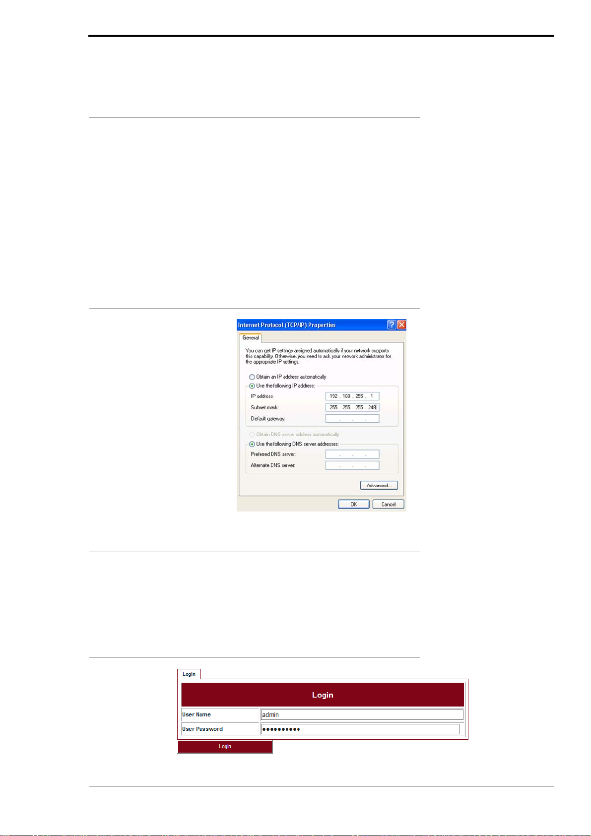
Before logging into the LITE Web interface, the network configuration of the PC must be set as
Figure 1. We suggest setting the PC IP address to 192.168.255.1 and subnet mask
255.255.255.248. This IP address is used to access LITE when the management PC is directly connected to LITE system. By default, the private IP address of LITE is 192.168.255.3 and the subnet
mask 255.255.255.248.
Commissioning
FIGURE 1.
PC network configuration
2.2 Commission steps
2.2.1 Logging in
Steps
Use the Web Browser to access the private IP address of LITE.
1.
FIGURE 2.
LITE, R1.0, Operation and Maintenance Guide, Issue 1
Step 1
5
Page 12
Commissioning
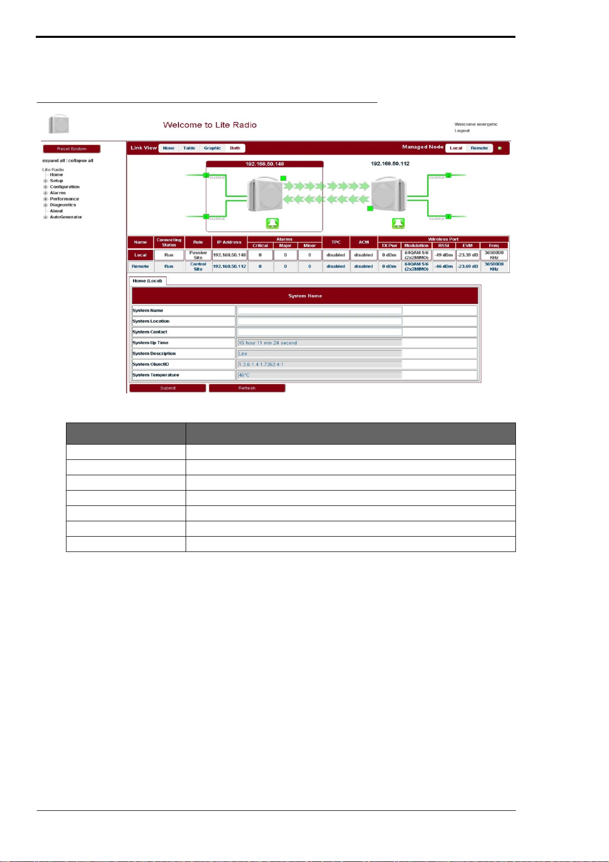
Enter User Name admin (by default) and User Password sysmanager (by default) and
2.
click Login. The home page of Link Viewer appears.
FIGURE 3.
Link Viewer
TABLE 3.
System Name Configure the system name to identify the NE.
System Location Configure the system location for easy management.
System Contact Configure the contact information for easy management.
System Up Time Show the system start up time. It is read only.
System Description Configure the system description for easy management.
System ObjectID
System Temperature Show the current temperature. It is read only.
System home
Parameter Description
2.2.2 Setting the management IP
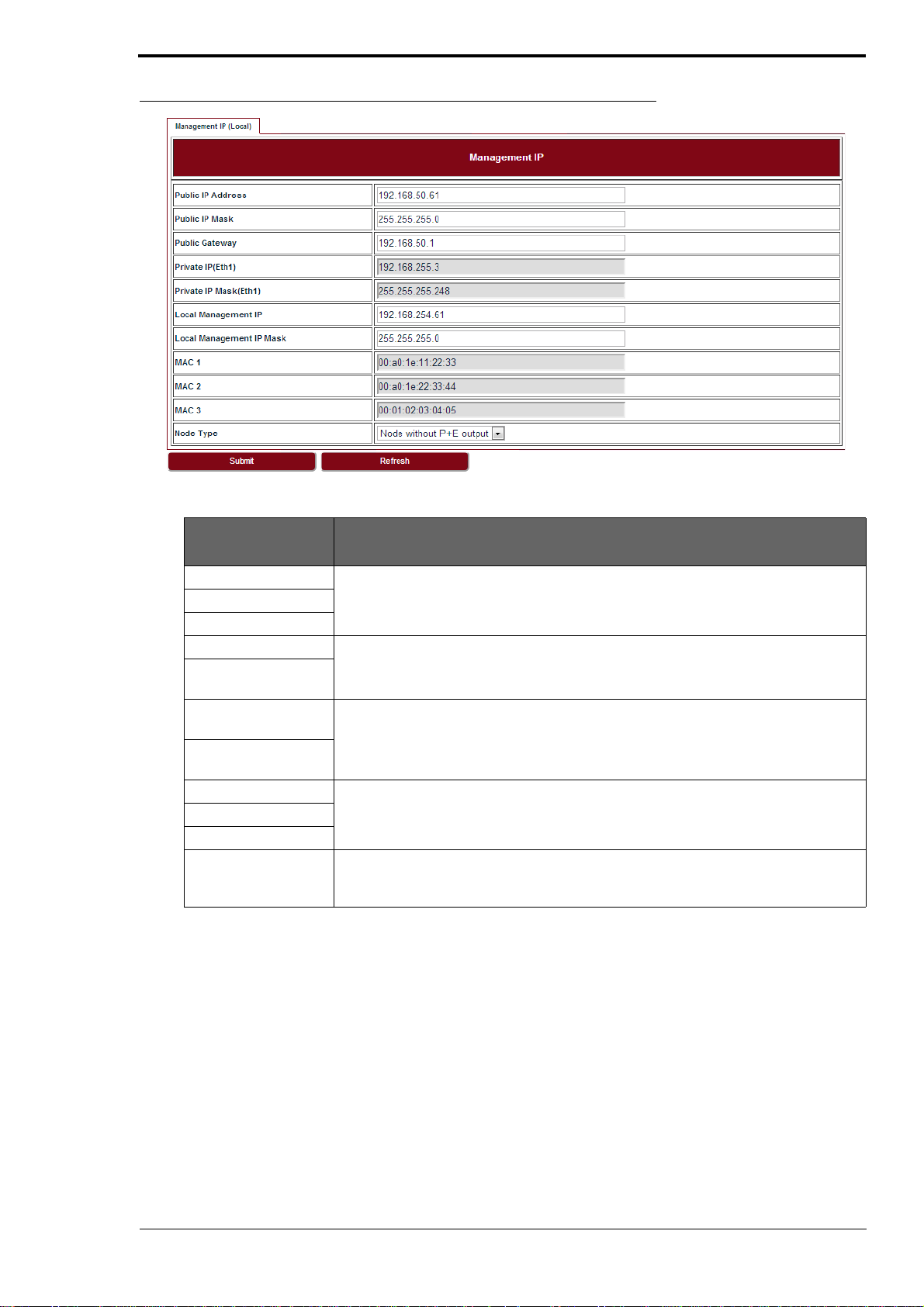
Go to Configuration > Management > IP tab (see Figure 4). The public management IP address
and local management IP address are to be set.
INFO
Don’t use IP address from 192.168.254.96 ~ 192.168.254.99. These 4 IP addresses are
reserved for internal use.
6
LITE, R1.0, Operation and Maintenance Guide, Issue 1
Page 13
Commissioning
FIGURE 4.
TABLE 4.
Management IP
Management IP
Parameter Description
Public IP Address Public IP is used to access LITE over Management VLAN (Tagged, typically using a
Public IP Mask
Public Gateway
Private IP (Eth 1) Private IP is used for commissioning.
Private IP Mask (Eth
1)
Local ManagementIPLocal Management IP is used to access LITE locally over one of the Ethe rnet ports
Local Management
IP Mask
MAC 1 Display the learned MAC addresses of Ethernet and Wireless ports.
MAC 2
MAC 3
Node Type This field is used in chain site configuration. When it is changed to Node with P+E
switch or other intranet connectivity). It is for in-band management.
untagged, for example, from a PC running WebLCT. It is also for out-of-band management.
output, the private IP would be automatically changed to 192.168.255.4, to avoid IP
address conflict in the chain site.
2.2.3 Setting the management VLAN
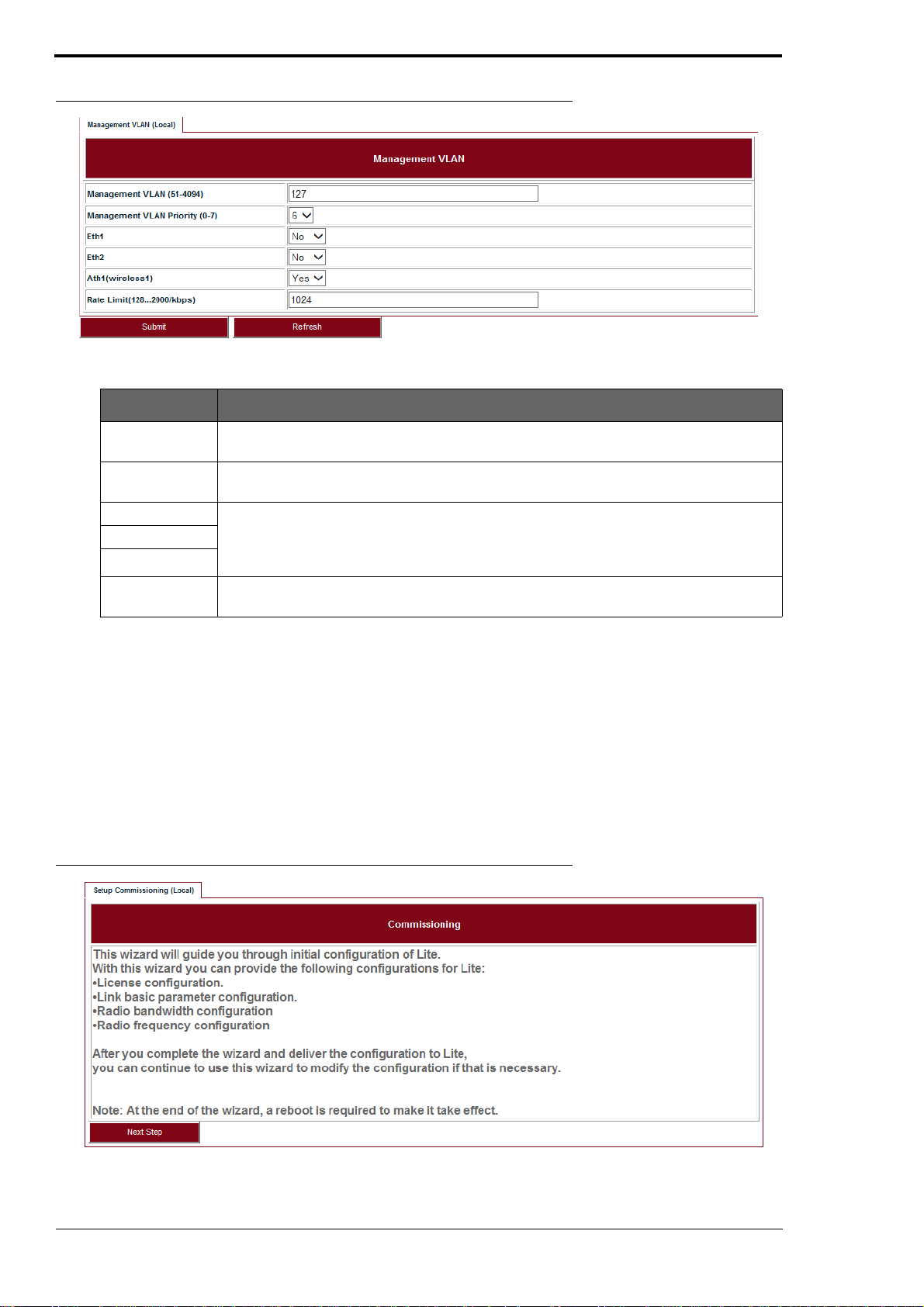
Go to Configuration > Management > Management VLAN tab (see Figure 5).
LITE, R1.0, Operation and Maintenance Guide, Issue 1
7
Page 14
Commissioning
FIGURE 5.
TABLE 5. Management VLAN
Management
VLAN
Management
VLAN Priority
Eth1 If the port is to be used as a part of the management VLAN, set to Yes. If no, it means
Eth2
Ath1(wireless1)
Rate Limit Configure the engress and eggress rate limit for management VLAN. Value from
Management VLAN
Parameter Description
Configure the management VLAN ID for remote login. VLAN range from 51 ~ 4096.
Default: 127.
Configure the management VLAN priority. Value from 0 ~ 7. Default: 6.
this port is removed from the management VLAN. If the management VLAN setting has
been set to yes, it doesn’t need to be added into the VLAN table in Ethernet > VLAN >
VLAN page.
128Kbps ~ 2Mbps. Default: 256Kbps.
2.2.4 Setting the radio parameters
Before setting the radio parameters, ensure that the correct radio standard is licensed for the geographic location where the radio is to be installed. For example: FCC for USA or Canada, ETSI for
Europe and Asia, etc.
It is also important to verify that the correct maximum speed required is licensed, as per the link
design specified for the radio in this location.
Steps
1.
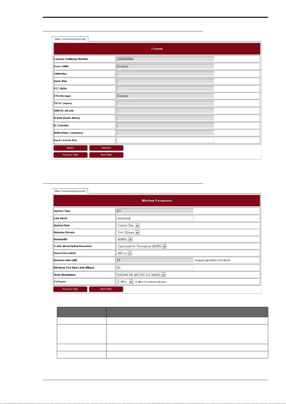
Go to Setup > Commissioning tab (see Figure 6) and click Next Step.
FIGURE 6.
Step 1
2.
Input the license key and click Modify. Click Refresh to make sure of the configuration.
8
LITE, R1.0, Operation and Maintenance Guide, Issue 1
Page 15
Commissioning
FIGURE 7.
Step 2
3.
FIGURE 8.
TABLE 6.
Set up wireless parameters according to Table 6.
Step 3
Wireless parameters
Parameter Description
Link Name Up to 32 characters, and both numbers and characters are supported.
System Role Control Site or Passive Site.
One end of LITE should be configured as the Control Site, a nd the other end the
Passive Site.
Antenna Stream V+H Stream supported.
Bandwidth 40 MHz or 20MHz.
LITE, R1.0, Operation and Maintenance Guide, Issue 1
9
Page 16
Commissioning
TABLE 6.
Traffic Mode (Uplink/
Downlink)
Guard Interval 400 ns or 800 ns.
Wireless Port Rate
Limit
Static Modulation If ACM is disabled, LITE will use Static Modulation as Tx side modulation. This is
Tx Power Tx power on each radio. Limited by EIRP. This rate limit is automatically assign ed
Wireless parameters
Parameter Description
50/50, 70/30, 30/70
For 50/50, the uplink and downlink have same bandwidth. For 70/30, it supports
asymmetric traffic for uplink and downlink.
If the maximum multi-path delay spreads more than 400 ns, we suggest to use
800 ns.
Rate limit on wireless port.
the modulation selected for this link and will not change unless ACM is enabled.
based on the modulation selected.
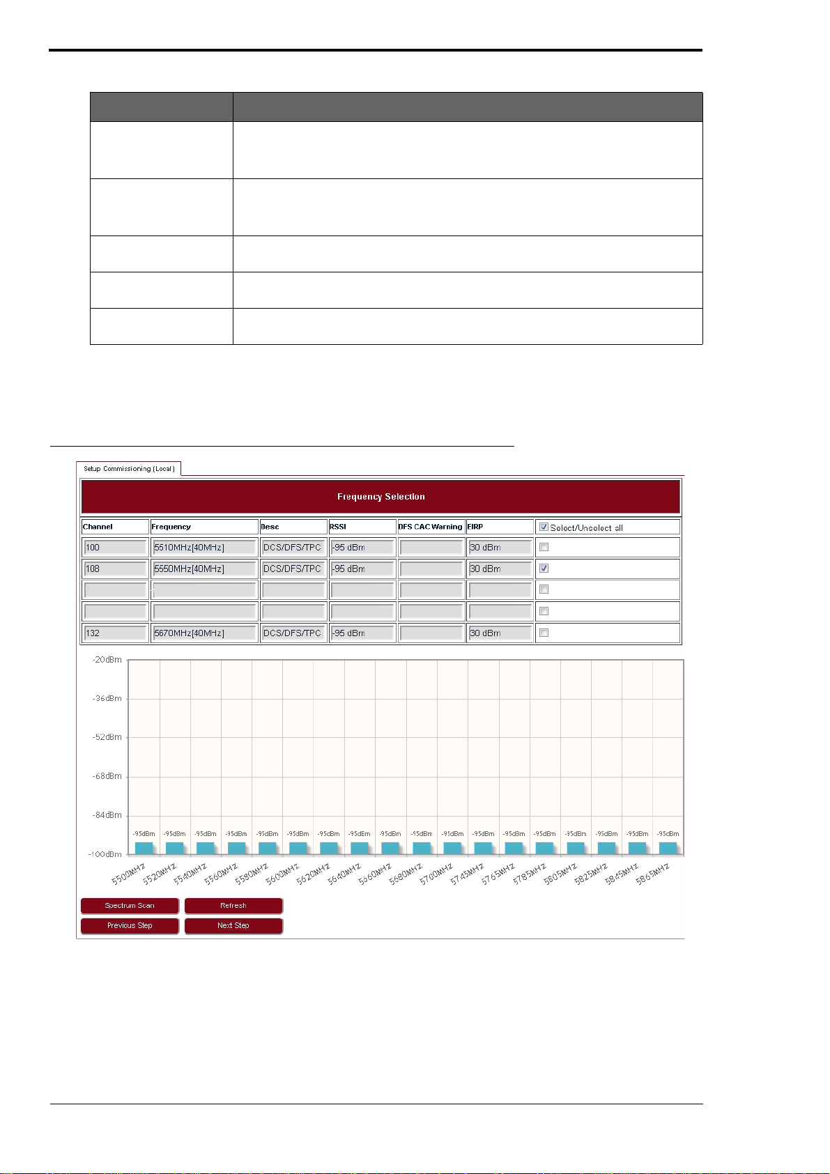
In Frequency Selection p age, click Spectrum Scan and Rx RSSI for each channel will be
4.
shown on Link Viewer (see Figure 9). This page allows the user to see which channels are
currently in use by other radio equipment nearby. It also allows the user to select specific
channels for this radio link.
FIGURE 9.
Step 4
10
5.
It is suggested to select one or more channels from those available which have RSSI that is
lower than -90 dBm in Figure 9. After selection, click Next Step.
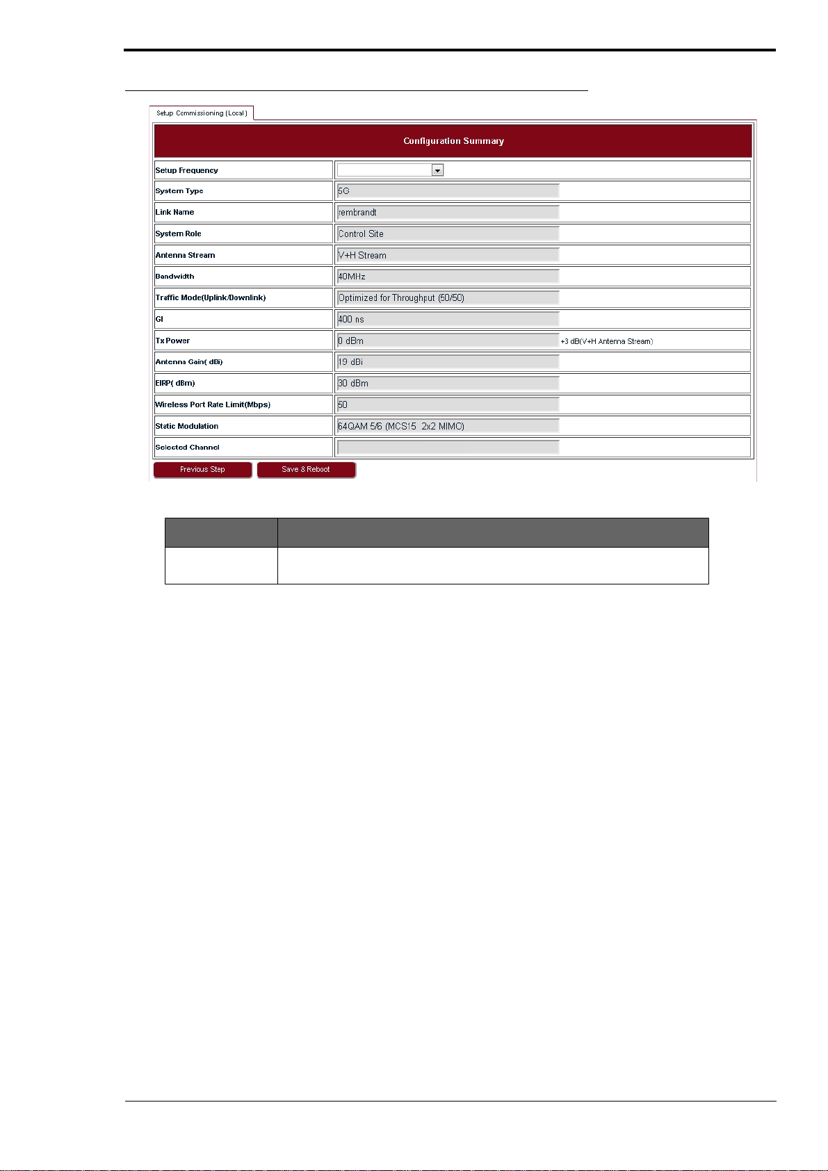
In Configuration Summary page, set the Setup Frequency field according to Table 7.
6.
LITE, R1.0, Operation and Maintenance Guide, Issue 1
Page 17
Commissioning
FIGURE 10.
Step 6
5550MHz (108)
5550MHz (108)
TABLE 7.
Configuration Summary
Parameter Description
Setup Frequency The setup frequency is the initial frequency to be used when the link is set
up.
7.
Check all the configurations in Figure 10 and click Save & Reboot so that LITE will restart
and run under new configurations.
LITE, R1.0, Operation and Maintenance Guide, Issue 1
11
Page 18

Commissioning
12
LITE, R1.0, Operation and Maintenance Guide, Issue 1
Page 19
3 System configuration
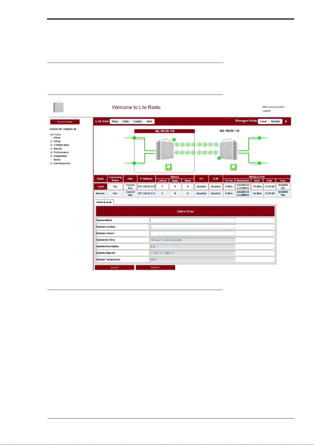
3.1 System home
Go to the Home page to set the parameters.
System configuration
FIGURE 11.
System Home
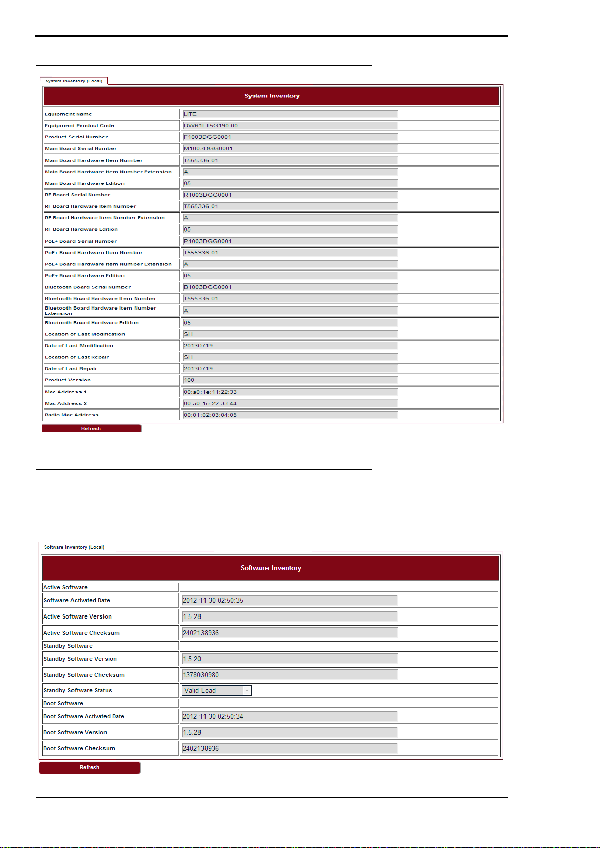
3.2 System inventory
Go to Configuration > System > System Inventory page.
LITE, R1.0, Operation and Maintenance Guide, Issue 1
13
Page 20
System configuration
FIGURE 12.
System inventory
3.3 Software inventory
Go to Configuration > System > Software Inventory page.
FIGURE 13.
Software inventory
14
LITE, R1.0, Operation and Maintenance Guide, Issue 1
Page 21
3.4 Software management
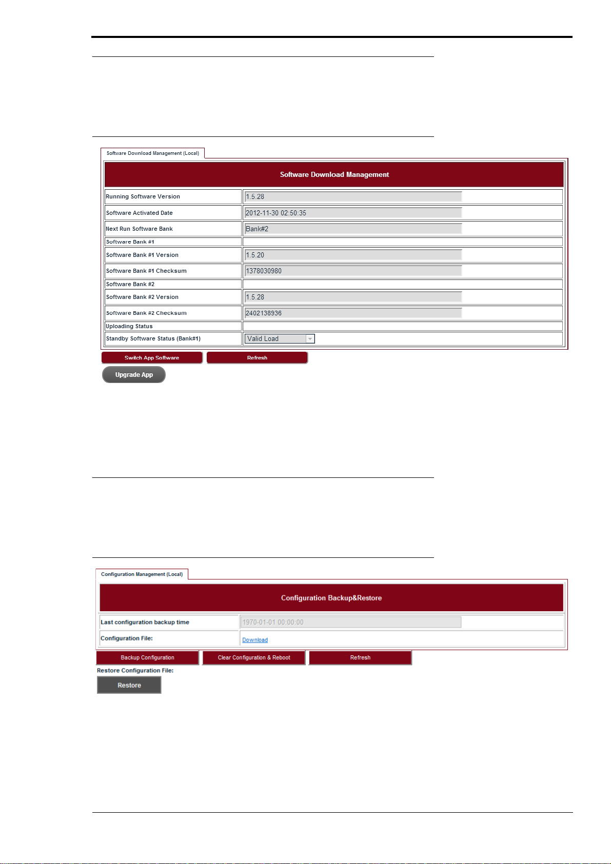
Steps
1.
Go to Configuration > System > Software Management page.
System configuration
FIGURE 14.
2.
3.
4.
Software download management
Click Upgrade App and go to the right folder path to open the target software.
Click Switch App Software, confirm the Next Run Software Bank is switched correctly.
Click Reboot System. After reboot, LITE would start up with the new software.
3.5 Configuration management
Steps
Go to Configuration > System > Configuration Management page.
1.
FIGURE 15.
Configuration backup & restore
Click Backup Configuration and click the Download link to download the backup configu-
2.
ration file.
3.
Click Clear Configuration & Reboot, confirm to clear configuration and reboot.
4.
Click Restore and go to the right folder path to open the target configuration file.
LITE, R1.0, Operation and Maintenance Guide, Issue 1
15
Page 22
System configuration
3.6 P+E output
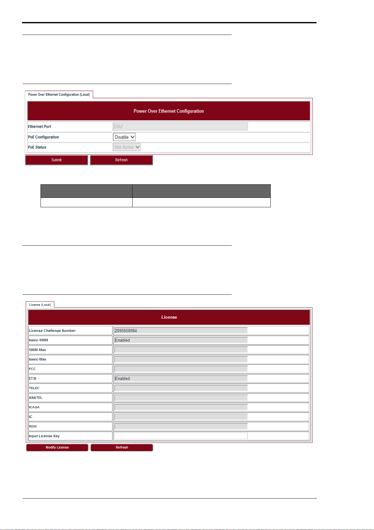
Steps
1.
Go to Configuration > System > P+E Output page.
FIGURE 16.
TABLE8.
P+E output
PoE Configuration Enable or Disable. Default: Disable.
Click Submit to apply the configuration.
2.
3.7 Licensing
P+E output configuration
Parameter Description
Steps
1.
FIGURE 17.
Go to Configuration > System > Licensing page.
License
16
2.
Click Modify License to make change on the license information.
LITE, R1.0, Operation and Maintenance Guide, Issue 1
Page 23
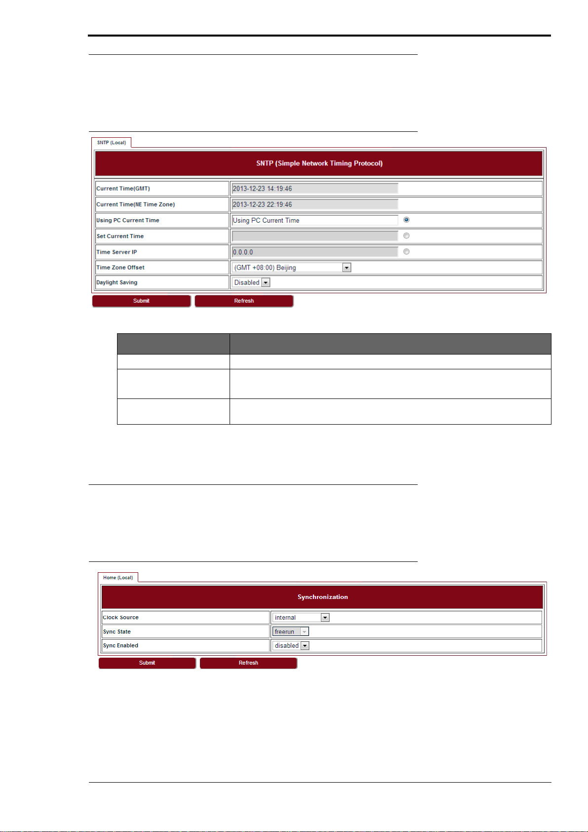
3.8 SNTP
Steps
1.
Go to Configuration > System > SNTP page.
System configuration
FIGURE 18.
TABLE9.
Time Server IP It is used to get SNTP time from Time Server.
Time Zone Offset Configure the NE time zone when Time Server is configured.
Daylight Saving Configure the NE daylight saving when Time Server is configured. Value is
SNTP
SNTP
Parameter Description
Values are from -12 ~ +13.
Enabled or Disabled.
To set SNTP, fill out all the parameters and click Submit.
2.
3.9 Synchronization
Steps
1.
Go to Configuration > System > Synchronization page.
FIGURE 19.
Synchronization
To set Synchronization, fill out all the parameters and click Submit.
2.
LITE, R1.0, Operation and Maintenance Guide, Issue 1
17
Page 24

System configuration
18
LITE, R1.0, Operation and Maintenance Guide, Issue 1
Page 25
4 Wireless radio configuration
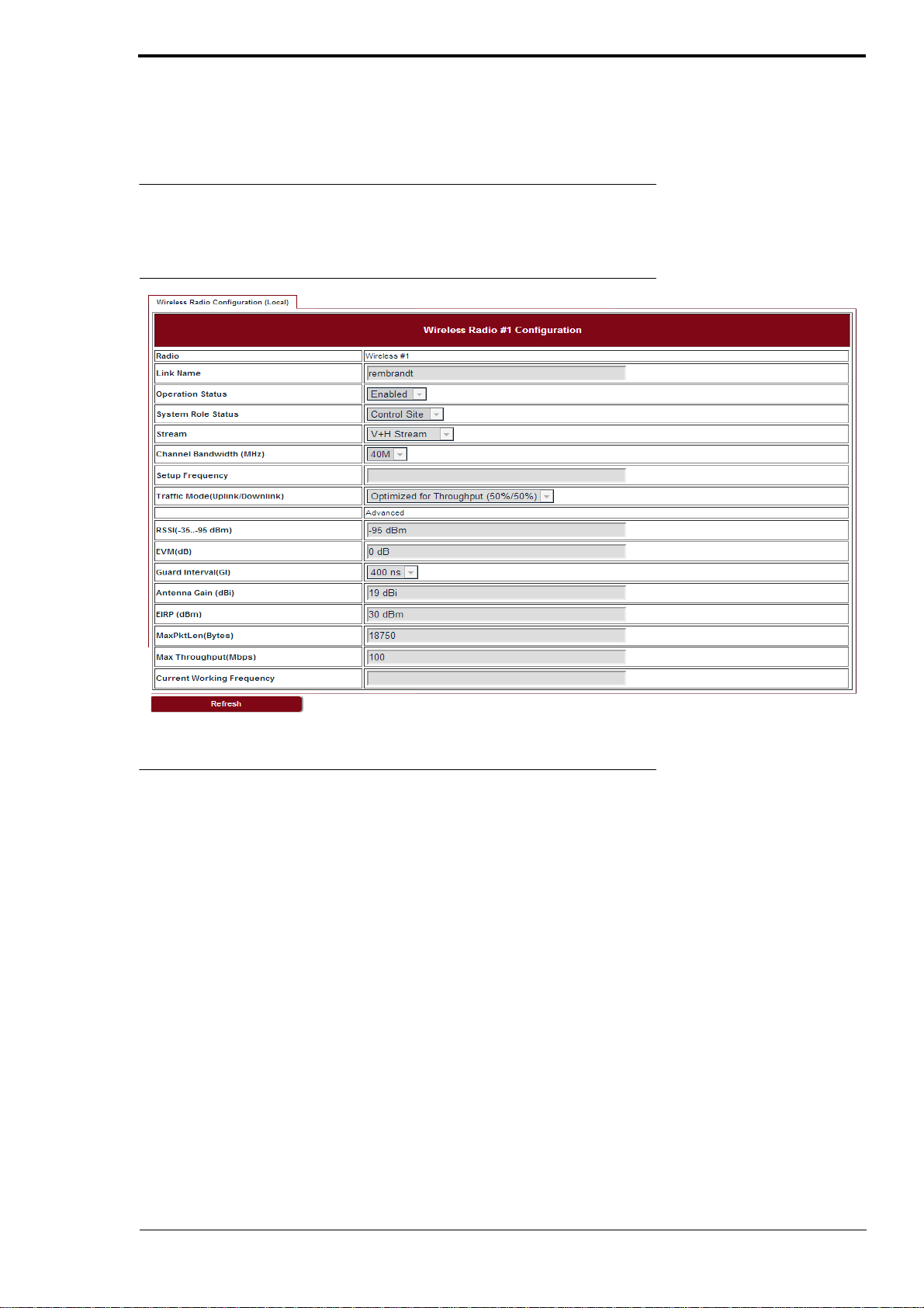
4.1 Wireless radio #1 configuration
Go to Configuration > Wireless Radio > Wireless page.
Wireless radio configuration
FIGURE 20.
Wireless radio #1 configuration
5550MHz (108)
5550MHz
4.2 Dynamic Channel Selection
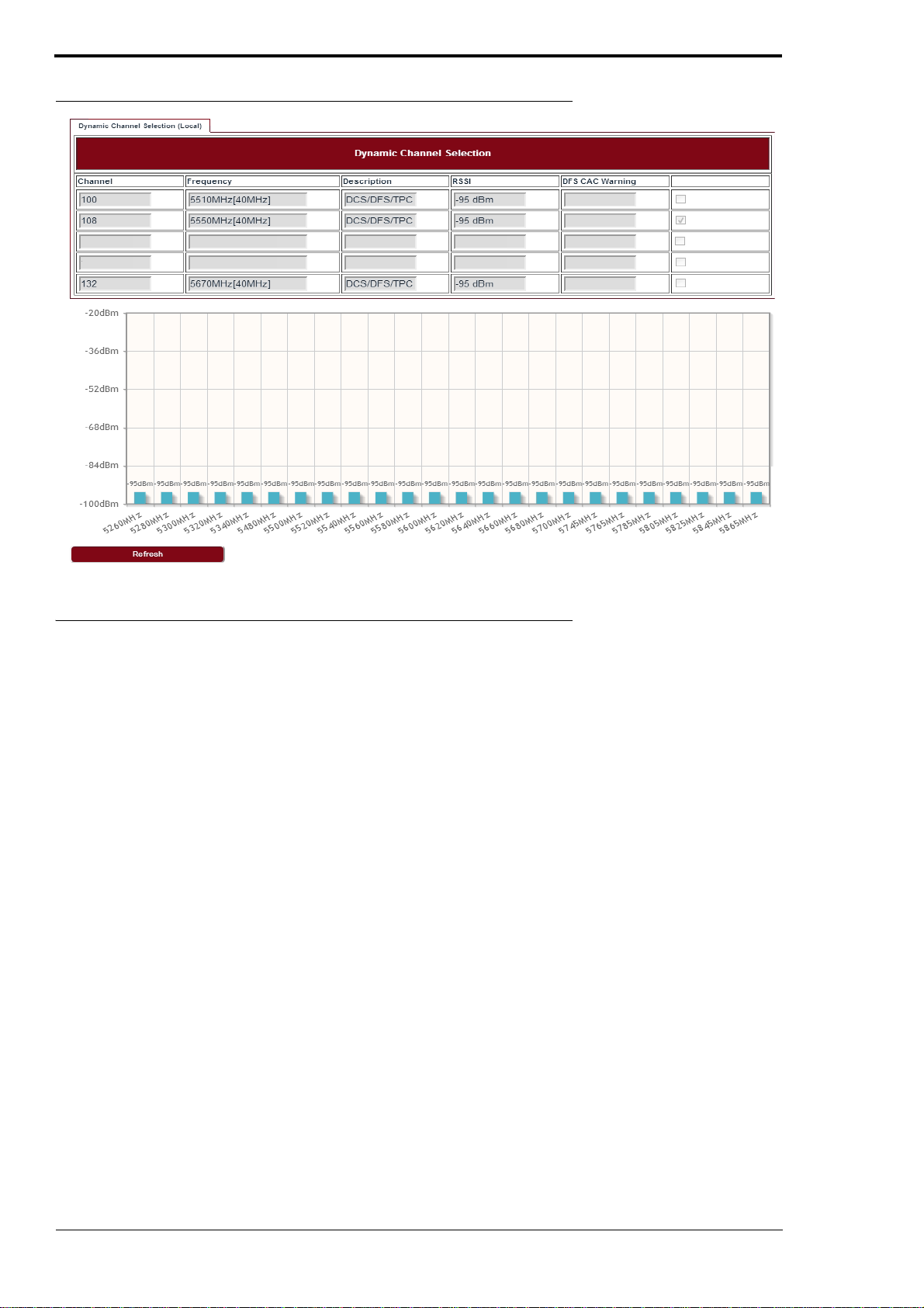
Go to Configuration > Wireless Radio > DCS page.
LITE, R1.0, Operation and Maintenance Guide, Issue 1
19
Page 26
Wireless radio configuration
FIGURE 21.
DCS
4.3 Received Signal Strength Indication
Go to Configuration > Wireless Radio > RSSI page.
20
LITE, R1.0, Operation and Maintenance Guide, Issue 1
Page 27
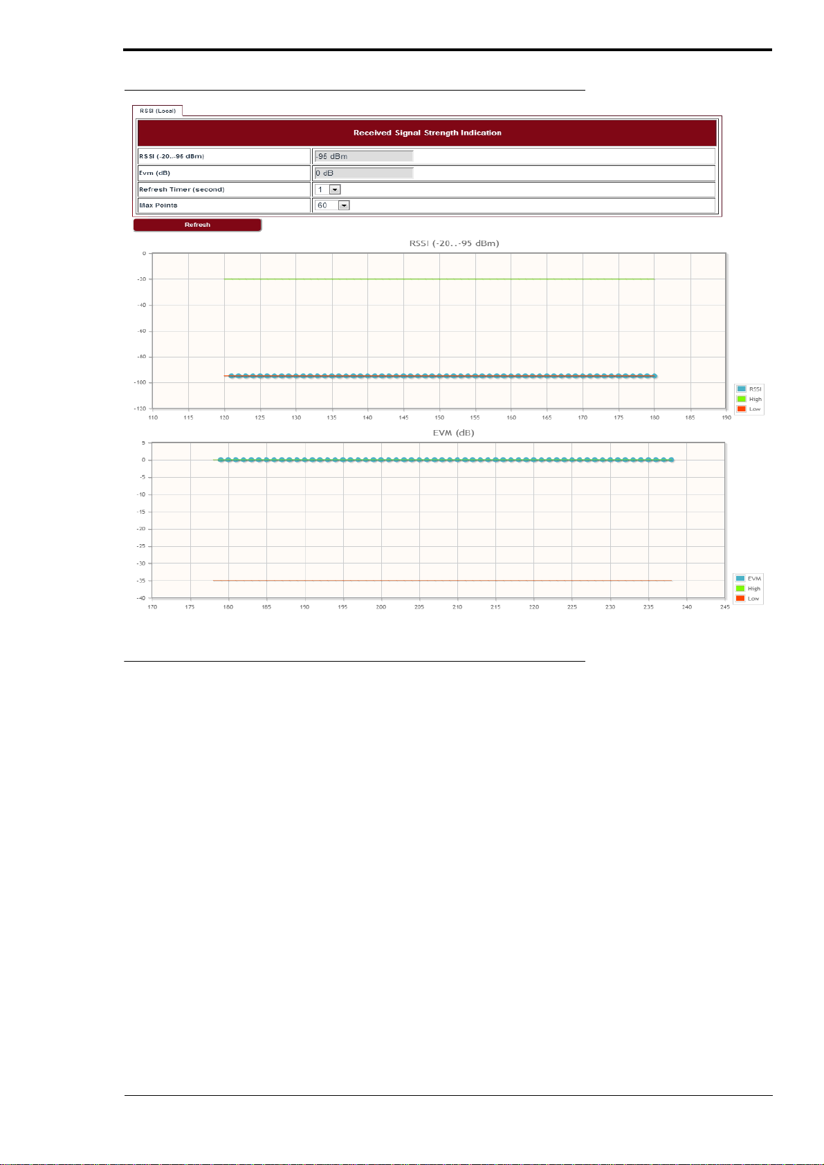
FIGURE 22. RSSI
Wireless radio configuration
4.4 Modulation and ACM
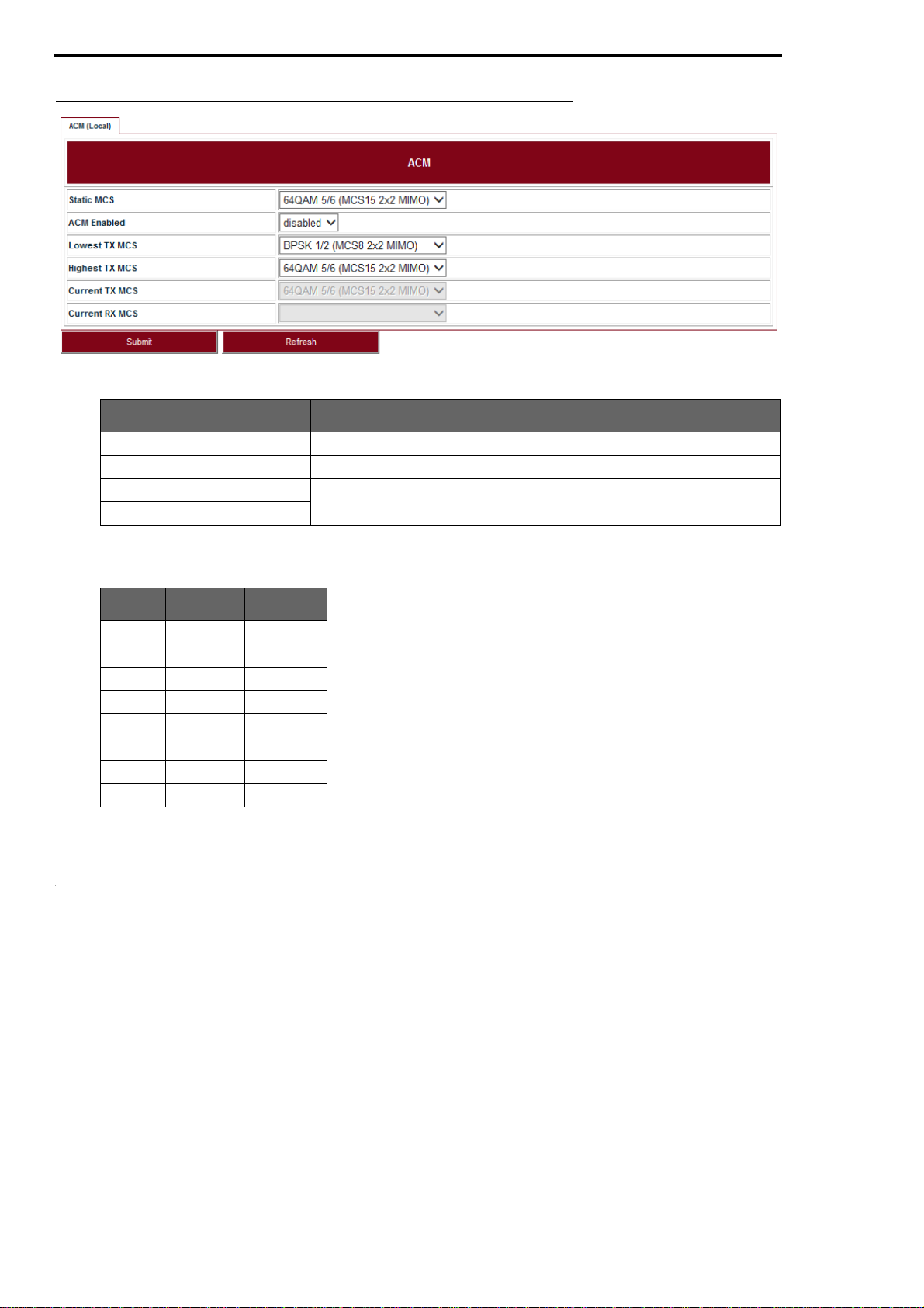
Go to Configuration > Wireless Radio > ACM page to set the modulation and ACM parameters.
LITE, R1.0, Operation and Maintenance Guide, Issue 1 21
Page 28
Wireless radio configuration
FIGURE 23. ACM
TABLE 10. ACM
Parameter Description
Static MCS The Tx modulation when ACM is disabled.
ACM Enabled Enabled or Disabled.
Lowest TX MCS MCS range for LITE, when ACM is enabled.
Highest TX MCS
TABLE 11. Default ACM adjustment threshold value
MCS Low (dB) High (dB)
MCS15 -20.5 NA
MCS14 -19.5 -21.5
MCS13 -18.5 -20.5
MCS12 -14 -19.5
MCS1 1 -12 -15
MCS10 -10 -13
MCS9 -9 -11
MCS8 NA -10
4.5 Tx power and Adaptive Transmit Power Control (ATPC)
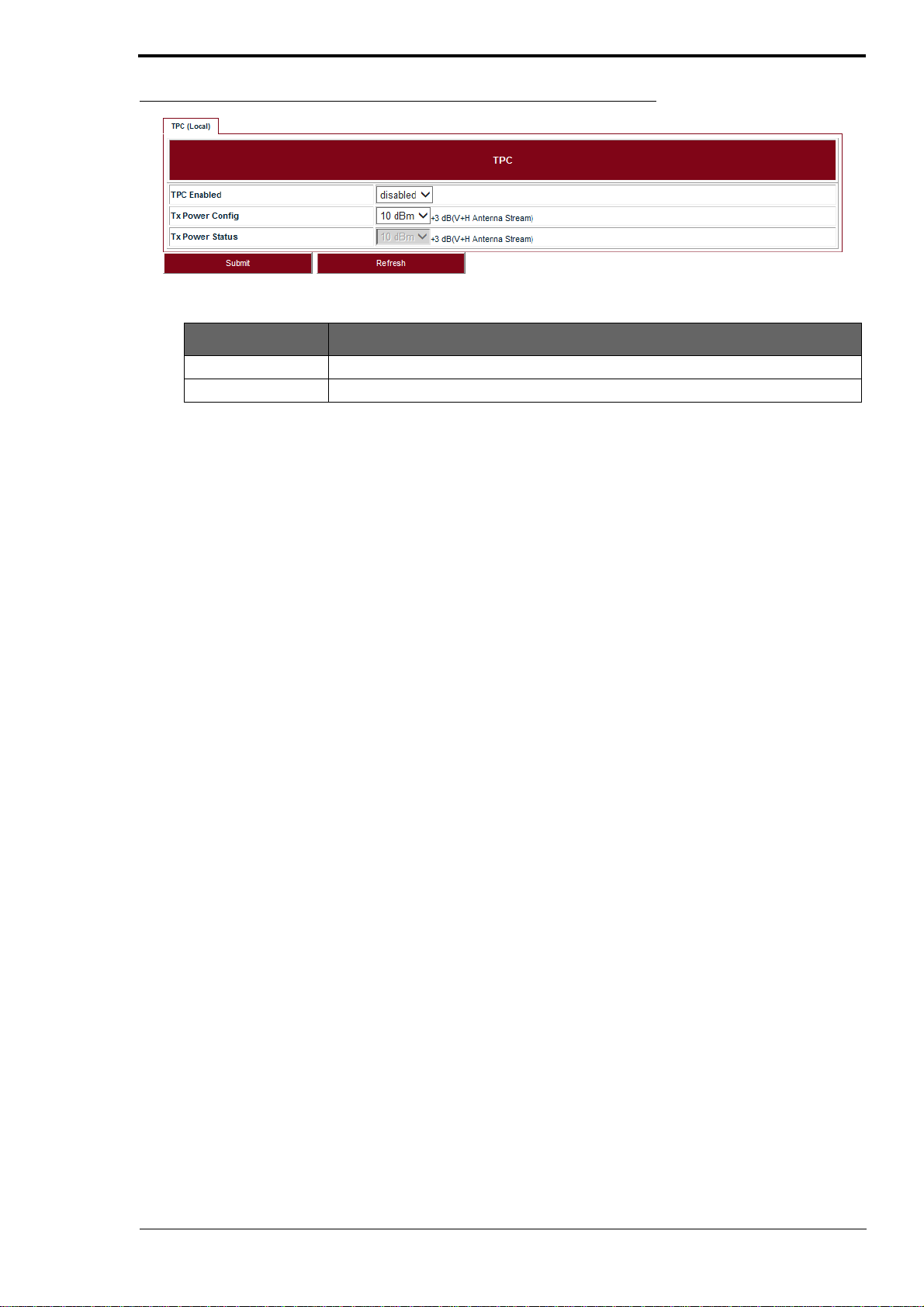
Adaptive Transmit Power Control (ATPC) allows a LITE system to adjust its transmit power to compensate for far end signal loss caused by changes in atmospheric conditio ns, e.g., heavy rain. ATPC
maintains the RSSI at the ATPC threshold, which is system mode dependent, and a djusts the transmit power as necessary in order to maintain the ATPC threshold during fading conditions.
Go to Configuration > Wireless Radio > TPC page.
22 LITE, R1.0, Operation and Maintenance Guide, Issue 1
Page 29
Wireless radio configuration
FIGURE 24. TPC
TABLE 12. TPC
Parameter Description
ATPC Enabled Enabled or Disabled. Default: Disabled.
Tx Power Config Set the Tx Power on each chain, it is limited by local regulations.
LITE, R1.0, Operation and Maintenance Guide, Issue 1 23
Page 30

Wireless radio configuration
24 LITE, R1.0, Operation and Maintenance Guide, Issue 1
Page 31
5 Ethernet configuration
5.1 Ports
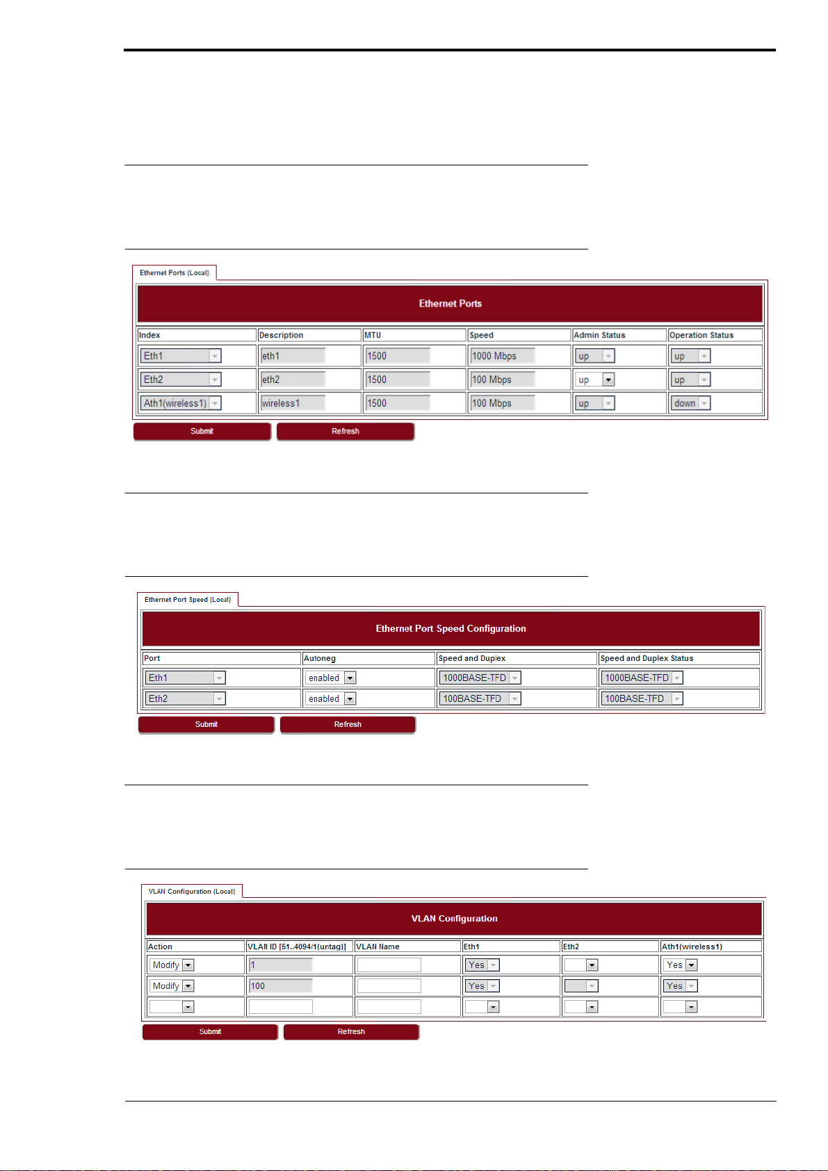
Go to Configuration > Ethernet > Port > Ports page to set the Ethernet ports.
FIGURE 25. Ethernet ports
Ethernet configuration
5.2 Speed
Go to Configuration > Ethernet > Port > Speed page to set the Ethernet port speed configuration.
FIGURE 26. Ethernet port speed configuration
5.3 VLAN management
Go to Configuration > Ethernet > VLAN > VLAN tab.
FIGURE 27. VLAN configuration
LITE, R1.0, Operation and Maintenance Guide, Issue 1 25
Page 32
Ethernet configuration
To create a VLAN, select Create in the Action drop-down list and fill out all the parameters and click
Submit.
Similarly, a VLAN can be modified or deleted by selecting Modify or Delete in the Action drop-down
list and click Submit.
5.4 QoS scheduler
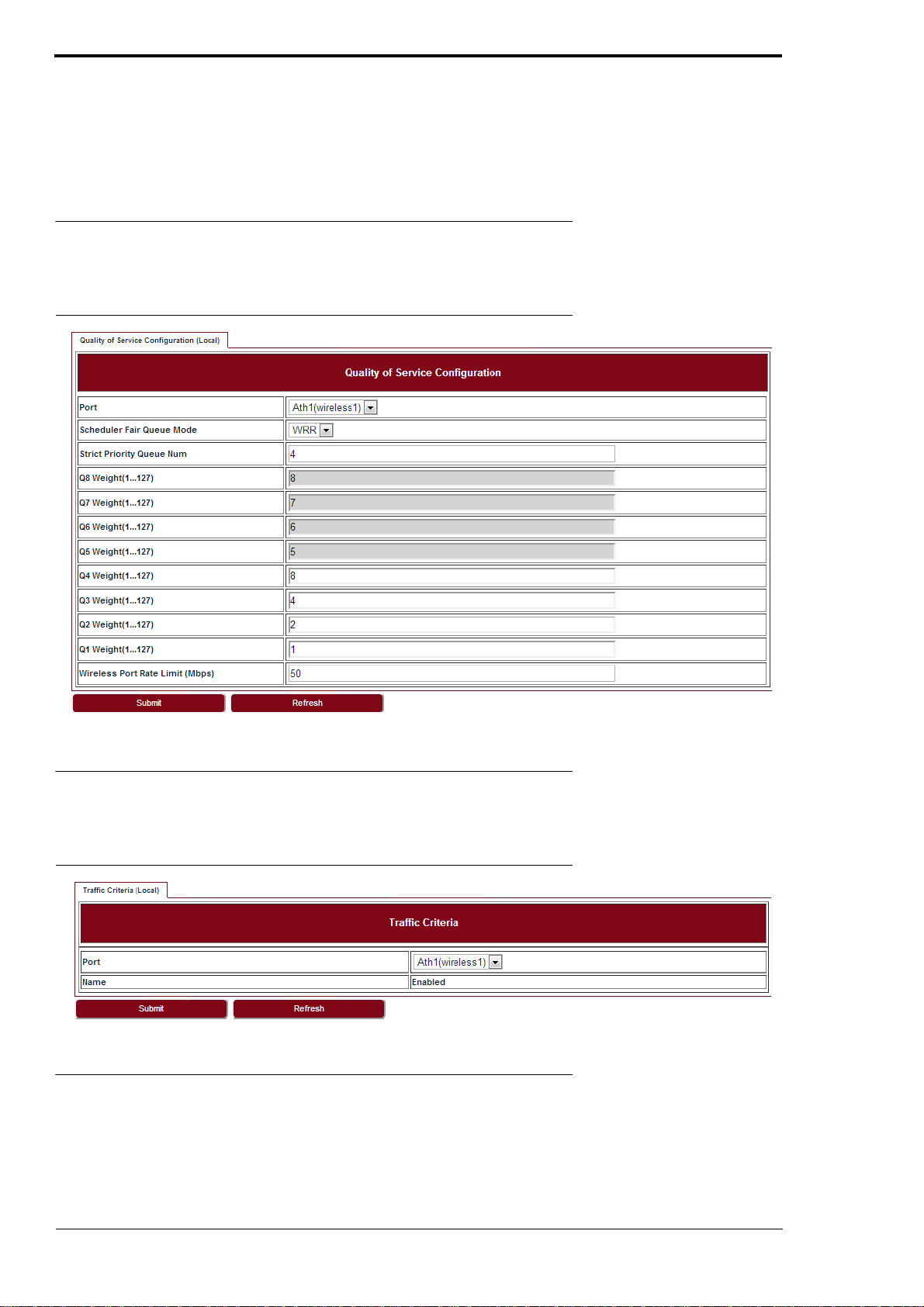
Go to Configuration > Ethernet > QoS > QoS page to set the QoS scheduler.
FIGURE 28. Quality of Service Configuration
5.5 Traffic criteria
Go to Configuration > Ethernet > QoS > Tra ffic Criteria page to set the traffic criteria.
FIGURE 29. Traffic Criteria
5.6 IP priority
Go to Configuration > Ethernet > QoS > IP Priority page to set the IP priority.
26 LITE, R1.0, Operation and Maintenance Guide, Issue 1
Page 33
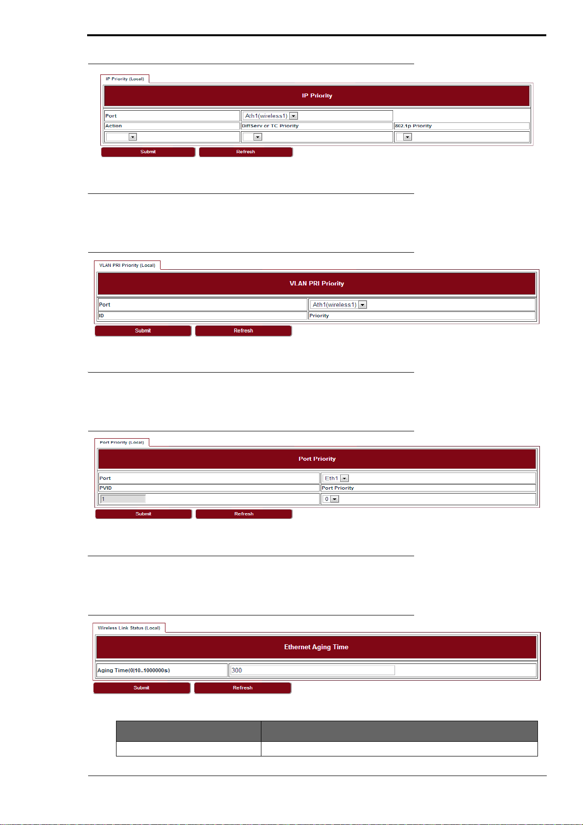
FIGURE 30. IP priority
5.7 VLAN PRI priority
Go to Configuration > Ethernet > QoS > Vlan PRI Priority page to set the VLAN PRI priority.
FIGURE 31. VLAN PRI priority
Ethernet configuration
5.8 Port priority
Go to Configuration > Ethernet > QoS > Port Priority page to set the Port priority.
FIGURE 32. Port priority
5.9 Aging time
Go to Configuration > Ethernet > FDB > Aging Time page to set the Ethernet aging time.
FIGURE 33. Aging time
TABLE 13. Aging time
Parameter Description
Aging Time 0 ~ 3825s with steps of 15s.
LITE, R1.0, Operation and Maintenance Guide, Issue 1 27
Page 34
Ethernet configuration
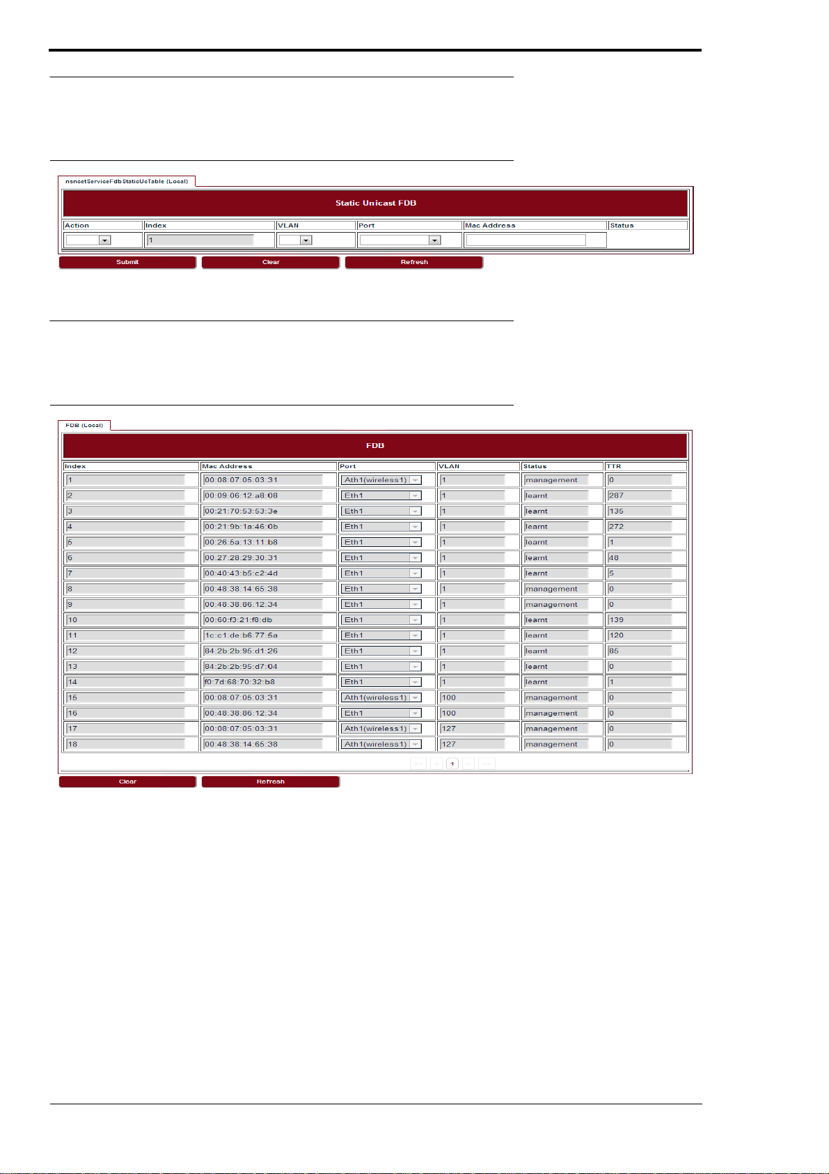
5.10 Static Unicast FDB
Go to Configuration > Ethernet > FDB > Static Unicast FDB page to set the Static Unicast FDB.
FIGURE 34. Static Unicast FDB
5.11 All FDB
Go to Configuration > Ethernet > FDB > All FDB page to see all FDB.
FIGURE 35. All FDB
28 LITE, R1.0, Operation and Maintenance Guide, Issue 1
Page 35
6 Management
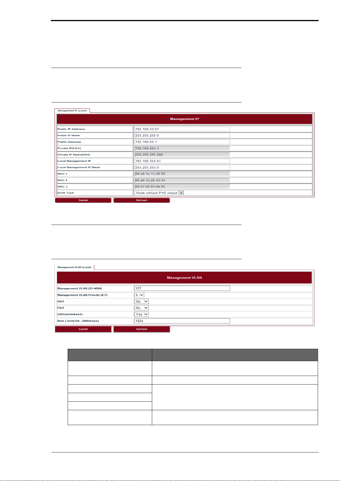
6.1 IP
Go to Configuration > Management > IP page to set the management IP.
FIGURE 36. Management IP
Management
6.2 Management VLAN
Go to Configuration > Management > Management VLAN page to set the Management VLAN.
FIGURE 37. Management VLAN
TABLE 14. Management VLAN
Parameter Description
Management VLAN Configure the management VLAN ID for remote login. Values are 51 ~
4094. Default: 127.
Management VLAN Priority Configure the management VLAN priority. Values are 0 ~ 7. Default: 6.
Eth1 Configure which port is in management VLAN.
Eth2
Ath1 (wireless1)
Rate Limit It is engress and eggress rate limit for management VLAN. Values are
128Kbps ~ 2Mbps. Default: 256Kbps.
LITE, R1.0, Operation and Maintenance Guide, Issue 1 29
Page 36
Management
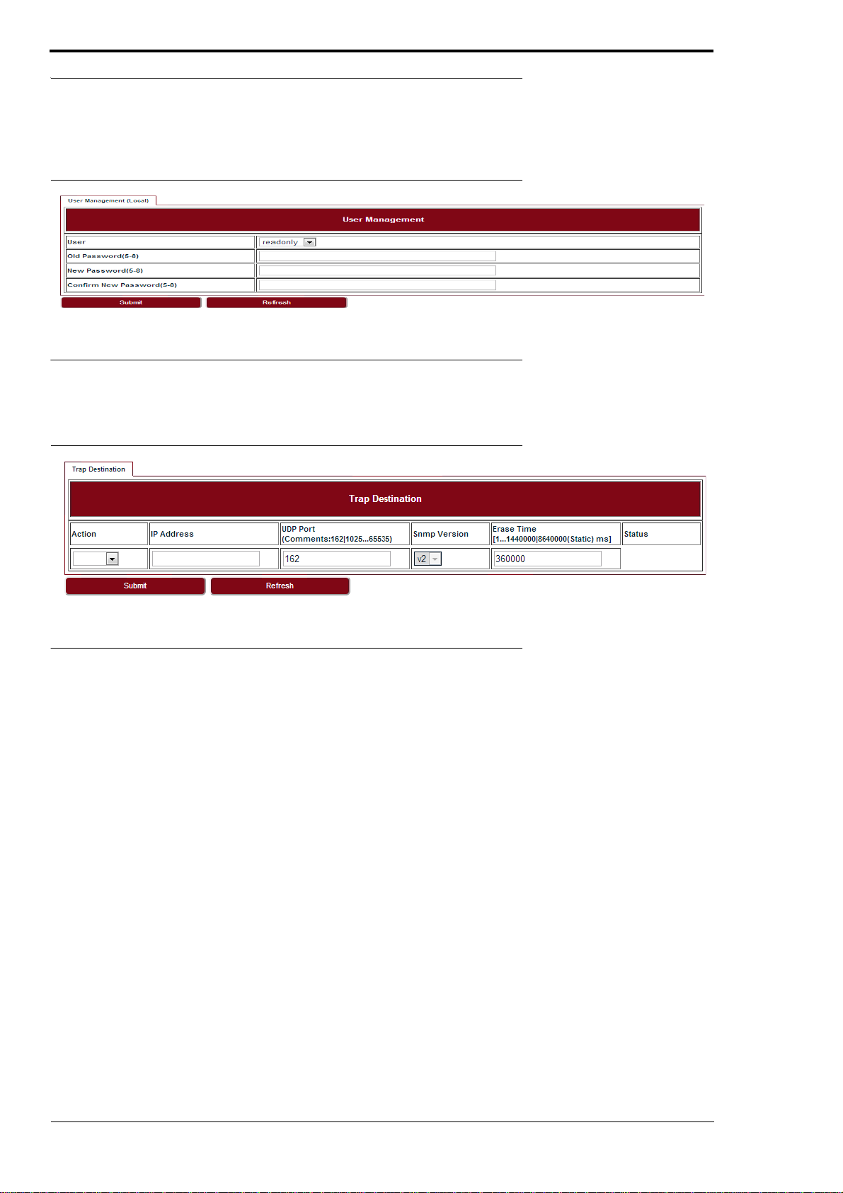
6.3 SNMP
Go to Configuration > Management > SNMP page to change the User Name and Password.
Default User Name is admin, default Password is sysmanager.
FIGURE 38. User management
6.4 Trap
Go to Configuration > Management > Trap page to set the Trap Destination parameters.
FIGURE 39. Trap
6.5 Event log
Go to Configuration > Management > Event Log page to see all the event logs.
30 LITE, R1.0, Operation and Maintenance Guide, Issue 1
Page 37
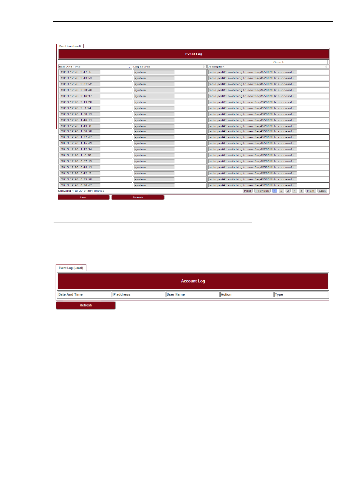
FIGURE 40. Event log
Management
6.6 Account log
Go to Configuration > Management > Account Log page to see all the account logs.
FIGURE 41. Account log
LITE, R1.0, Operation and Maintenance Guide, Issue 1 31
Page 38

Management
32 LITE, R1.0, Operation and Maintenance Guide, Issue 1
Page 39
7 Alarms
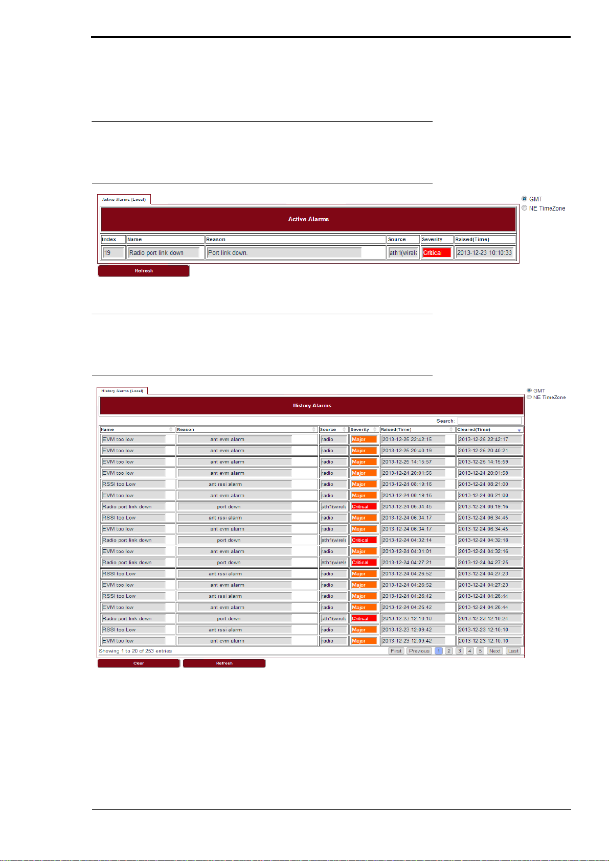
7.1 Active alarms
Go to Alarms > Active Alarms page to see the current alarm list.
FIGURE 42. Active alarms
Alarms
7.2 History alarms
Go to Alarms > History Alarms page to see the history alarm list.
FIGURE 43. History alarms
LITE, R1.0, Operation and Maintenance Guide, Issue 1 33
Page 40

Alarms
34
LITE, R1.0, Operation and Maintenance Guide, Issue 1
Page 41
8 Performance
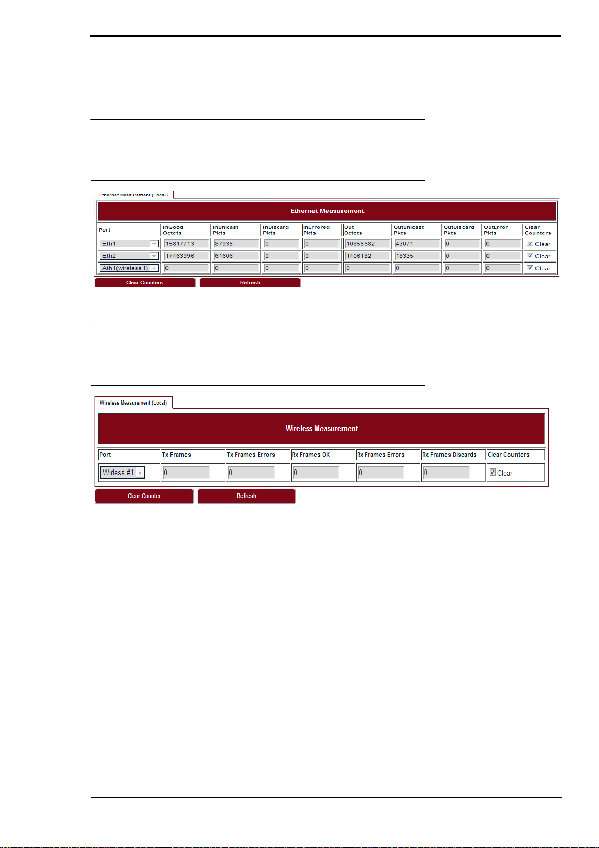
8.1 Ethernet
Go to Performance > Ethernet page to see the Ethernet measurement.
Performance
FIGURE 44.
Ethernet
8.2 Wireless
Go to Performance > Wireless page to see the Wireless measurement.
FIGURE 45.
Wireless
LITE, R1.0, Operation and Maintenance Guide, Issue 1
35
Page 42

Performance
36
LITE, R1.0, Operation and Maintenance Guide, Issue 1
Page 43
9 Diagnostics
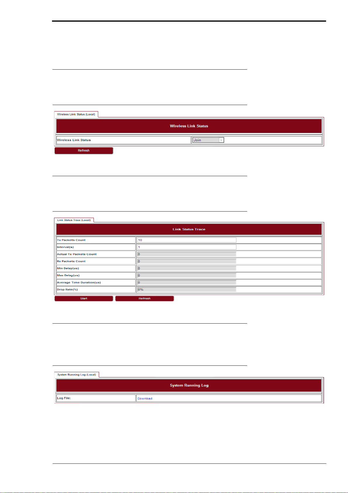
9.1 Link status
Go to Diagnostics > Link Status page to see the Wireless link status.
Diagnostics
FIGURE 46.
Link status
9.2 Link status trace
Go to Diagnostics > Link Status Trace page to see the link status trace.
FIGURE 47.
Link status trace
9.3 System running log
Go to Diagnostics > System Running Log page, click on “Download” to see the system running
log.
FIGURE 48.
LITE, R1.0, Operation and Maintenance Guide, Issue 1
System running log
37
Page 44

Diagnostics
38
LITE, R1.0, Operation and Maintenance Guide, Issue 1
Page 45
10 About
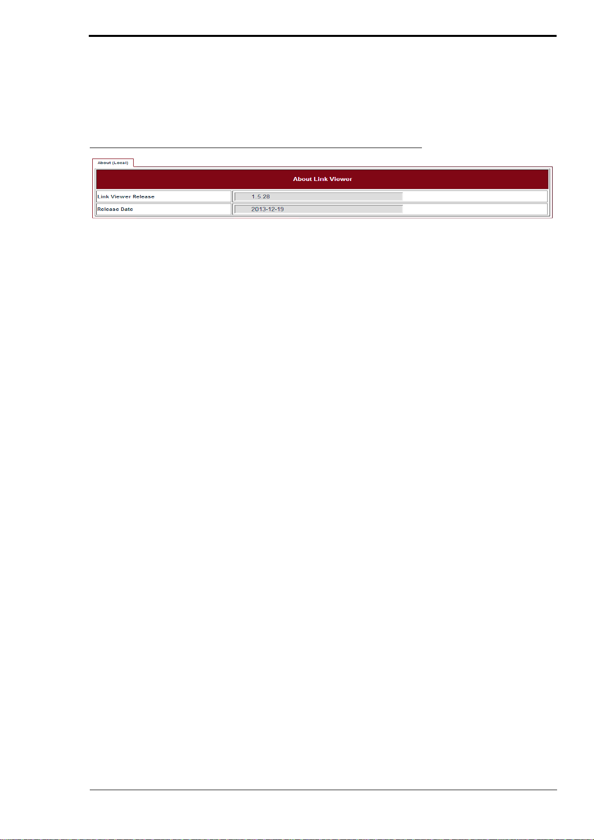
Go to the About page to see the information about the Link Viewer release.
About
FIGURE 49.
About Link Viewer
LITE, R1.0, Operation and Maintenance Guide, Issue 1
39
Page 46

About
40
LITE, R1.0, Operation and Maintenance Guide, Issue 1
Page 47
11 AutoGenerator
11.1 LiteDebug
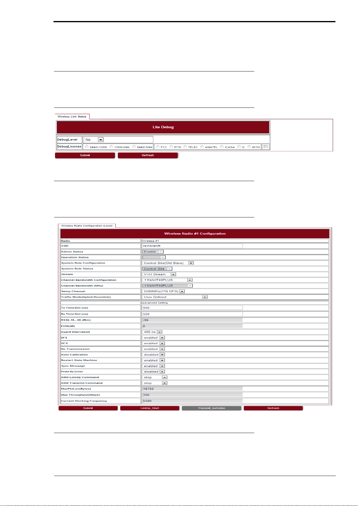
Go to AutoGenerator > LiteDebug page to set the Lite Debug parameters.
AutoGenerator
FIGURE 50.
LiteDebug
11.2 Wireless
Go to AutoGenerator > Wireless page to set the Wireless radio configuration.
FIGURE 51.
Wireless radio configuration
11.3 ACM
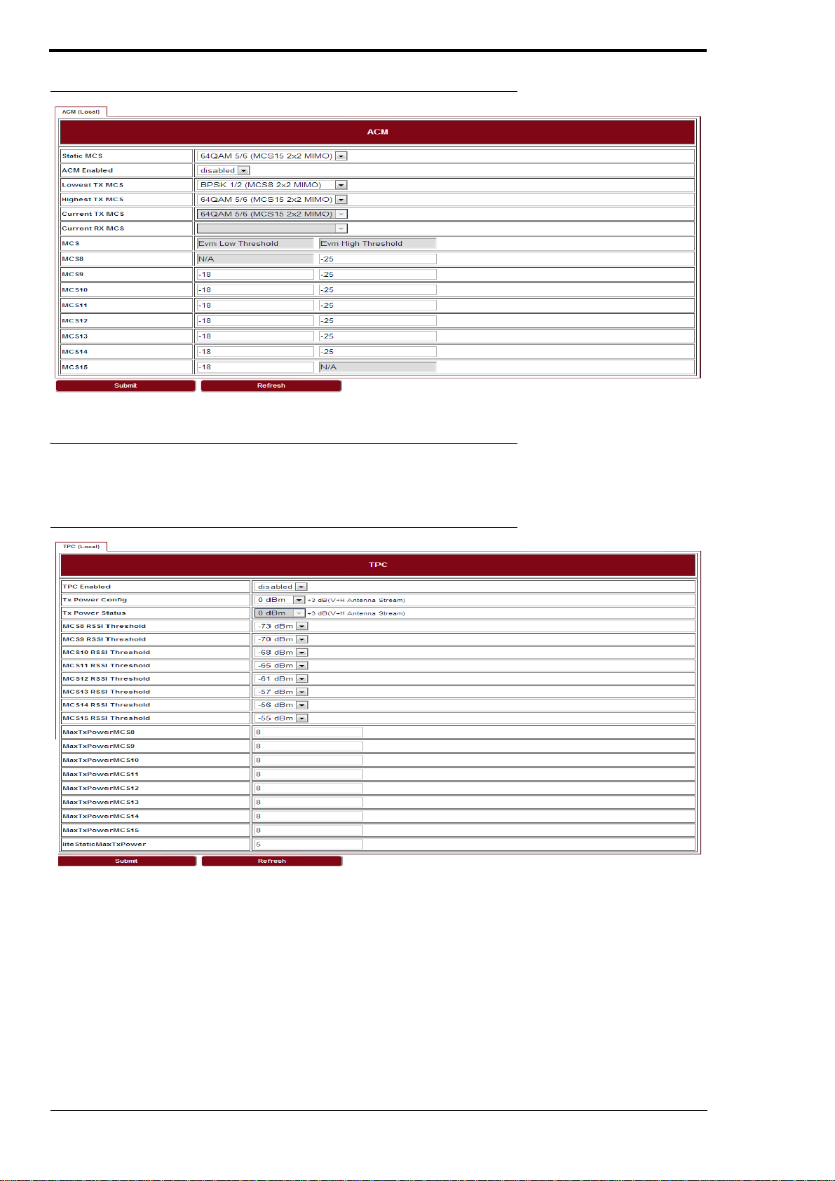
Go to AutoGenerator > ACM page to set the ACM parameters.
LITE, R1.0, Operation and Maintenance Guide, Issue 1
41
Page 48
AutoGenerator
FIGURE 52.
ACM
11.4 TPC
Go to AutoGenerator > TPC page to set the TPC parameters.
FIGURE 53.
TPC
42
LITE, R1.0, Operation and Maintenance Guide, Issue 1
Page 49

Operating Channel Declaration
Operating Channel List
Channels for 20MHz Channel Bandwidth
Channel Frequency Channel Frequency Channel Frequency
52 5260 MHz 56 5280 MHz 60 5300 MHz
64 5320 MHz 100 5500 MHz 104 5520 MHz
108 5540 MHz 112 5560 MHz 116 5580 MHz
132 5660 MHz 136 5680 MHz 140 5700 MHz
149 5745 MHz 153 5765 MHz 157 5785 MHz
161 5805 MHz 165 5825 MHz N/A N/A
Channels for 40MHz Channel Bandwidth
Channel Frequency Channel Frequency Channel Frequency
54 5270 MHz 62 5310 MHz 102 5510 MHz
110 5550 MHz 134 5670 MHz 151 5755 MHz
159 5795 MHz N/A N/A N/A N/A
Note: The channels in TDWR band (5600-5660MHz) was prohibited.
Page 50

Declaration of Conformity for RF Exposure
This microwave outdoor unit product has been found to be compliant to the
requirements set forth in CFR 47Section 1.1307 addressing RF Exposure from radio
frequency devices as defined in Evaluating Compliance with FCC Guidelines for
Human Exposure to Radio Frequency Electromagnetic Fields.
Antennas with less than 23.5 dBi gain should be located at a minimum of 39.03 cm in
more from the body of all persons.
Calculation Formula: Pd = (P
*G)/(4*pi*r2)
out
Where
Pd = power density in mW/cm2
Pout = output power to antenna in mW
G = gain of antenna in linear scale
Pi = 3.1416
r = distance between observation point and center of the radiator in cm
the limit of MPE, 1mW/cm².
Pd is
If we know the maximum gain of the antenna and the total power input to the antenna,
through the calculation, we will know the distance r where the MPE limit is reached.
43
LITE, R1.0, Operation and Maintenance Guide, Issue 1
Page 51

Federal Communications Commission (FCC) Interference Statement
This equipment has been tested and found to comply with the limits for a Class B digital device,
pursuant to Part 15 of the FCC Rules.
These limits are designed to provide reasonable protection against harmful interference in a
residential installation. This equipment generate, uses and can radiate radio frequency energy
and, if not installed and used in accordance with the instructions, may cause harmful
interference to radio communications.
However, there is no guarantee that interference will not occur in a particular installation. If this
equipment does cause harmful interference to radio or television reception, which can be
determined by turning the equipment off and on, the user is encouraged to try to correct the
interference by one of the following measures:
Reorient or relocate the receiving antenna.
Increase the separation between the equipment and receiver.
Connect the equipment into an outlet on a circuit different from that to which the receiver is
connected.
Consult the dealer or an experienced radio/TV technician for help.
This device complies with Part 15 of the FCC Rules. Operation is subject to the following two
conditions:
(1) This device may not cause harmful interference, and (2) this device must accept any
interference received, including interference that may cause undesired operation.
FCC Caution: Any changes or modifications not expressly approved by the party responsible
for compliance could void the user’s authority to operate this equipment.
RF exposure warning
This equipment complies with FCC radiation exposure limits set forth for an uncontrolled
environment.
This equipment must be installed and operated in accordance with provided instructions and
the antenna(s) used for this transmitter must be installed to provide a separation distance of at
least 39.03 cm from all persons and must not be collocated or operating in conjunction with any
other antenna or transmitter.
Page 52

IC Radiation Exposure Statement for Canada
This device complies with Industry Canada licence-exempt RSS standard(s).
Operation is subject to the following two conditions: (1) this device may not cause
interference, and (2) this device must accept any interference, including interference
that may cause undesired operation of the device.
Le présent appareil est conforme aux CNR d'Industrie Canada applicables aux
appareils radio exempts de licence. L'exploitation est autorisée aux deux conditions
suivantes : (1) l'appareil ne doit pas produire de brouillage, et (2) l'utilisateur de
l'appareil doit accepter tout brouillage radioélectrique subi, même si le brouillage est
susceptible d'en compromettre le fonctionnement.
Under Industry Canada regulations, this radio transmitter may only operate using an
antenna of a type and maximum (or lesser) gain approved for the transmitter by
Industry Canada. To reduce potential radio interference to other users, the antenna
type and its gain should be so chosen that the equivalent is otropically radiated power
(e.i.r.p.) is not more than that necessary for successful communication.
Conformément à la réglementation d'Industrie Canada, le présent émetteur radio peut
fonctionner avec une antenne d'un type et d'un gain maximal (ou inférieur) approuvé
pour l'émetteur par Industrie Canada. Dans le but de réduire les risques de brouillage
radioélectrique à l'intention des autres utilisateurs, il faut choisir le type d'antenne et
son gain de sorte que la puissance isotrope rayonnée équivalente (p.i.r.e.) ne
dépasse pas l'intensité nécessaire à l'établissement d'une communication
satisfaisante.
User manuals for transmitters equipped with detachable antennas shall also contain
the following notice in a conspicuous location:
This radio transmitter (identify the device by certification number, or model number if
Category II) has been approved by Industry Canada to operate with the antenna types
listed below with the maximum permissible gain and required antenna impedance for
each antenna type indicated. Antenna types not included in this list, having a gain
greater than the maximum gain indicated for that type, are strictly prohibited for use
with this device.
Le présent émetteur radio (identifier le dispositif par son numéro de certification ou
son numéro de modèle s'il fait partie du matériel de catégorie I) a été approuvé par
Industrie Canada pour fonctionner avec les types d'antenne énumérés ci-dessous et
ayant un gain admissible maximal et l'impédance requise pour chaque type d'antenne.
Les types d'antenne non inclus dans cette liste,ou dont le gain est supérieur au gain
maximal indiqué, sont strictement interdits pour l'exploitation de l'émetteur.
 Loading...