


Horizon COMPACT PlusTM
Wireless Ethernet
Release 1.0.1
Product Manual - Volume 1
Installation, Basic Configuration and Alignment
Version 1.2
NOTICE
This document contains confidential information, which is proprietary to DragonWave. No part of its contents can be used, copied, disclosed, or conveyed to any party in any manner whatsoever without prior written permission from DragonWave Inc.
Copyright © 2000 - 2012 DragonWave Inc.
Horizon Compact Plus Release 1.0.1 |
Wireless Ethernet Product User Manual – Volume 1 |

Table of Contents
1.0 |
USER MANUAL STRUCTURE..................................................................................... |
|
1 |
|
2.0 |
INTRODUCTION TO HORIZON COMPACT PLUS ............................................................ |
|
3 |
|
2.1 |
APPLICATIONS.................................................................................................................................... |
|
4 |
|
2.1.1 |
4G ............................................................................................................................................ |
|
4 |
|
2.1.2 3G CELLULAR BACKHAUL / ETHERNET EVOLUTION ...................................................................... |
|
4 |
||
2.1.3 |
LEASED LINE REPLACEMENT ...................................................................................................... |
|
4 |
|
2.1.4 LAST MILE FIBRE EXTENSION ..................................................................................................... |
|
4 |
||
2.2 |
TECHNICAL SPECIFICATIONS ............................................................................................................... |
|
5 |
|
3.0 |
PHYSICAL DESCRIPTION .......................................................................................... |
|
7 |
|
3.1 |
ETHERNET AND POWER CABLING ........................................................................................................ |
|
9 |
|
3.1.1 |
COPPER INTERFACE .................................................................................................................. |
|
9 |
|
3.1.2 |
OPTICAL INTERFACE .................................................................................................................. |
|
9 |
|
3.2 |
LIGHTNING PROTECTION ................................................................................................................... |
|
10 |
|
3.3 |
DUAL POLARIZATION RADIO MOUNT (DPRM) .................................................................................... |
|
11 |
|
3.4 |
POWER SPLIT RADIO MOUNT (PSRM) .............................................................................................. |
|
11 |
|
4.0 |
INSTALLATION REQUIREMENTS .............................................................................. |
|
13 |
|
4.1 |
LIGHTNING ARRESTOR UNITS............................................................................................................ |
|
16 |
|
4.1.1 OUTDOOR LIGHTNING ARRESTOR UNITS ................................................................................... |
|
16 |
||
4.1.2 INDOOR LIGHTNING ARRESTOR UNITS ...................................................................................... |
|
16 |
||
4.2 |
GROUNDED POWER FEEDS............................................................................................................... |
|
19 |
|
4.3 |
ETHERNET CABLING – COPPER INTERFACE ....................................................................................... |
|
20 |
|
4.3.1 USING OUTDOOR PONE UNIT................................................................................................... |
|
20 |
||
4.3.2 OUTDOOR PONE UNIT WEATHERPROOF GROMMET SEALS........................................................ |
21 |
|||
4.3.3 USING INDOOR PONE UNIT ...................................................................................................... |
|
21 |
||
4.3.4 ASSEMBLING THE RJ45 CONNECTOR........................................................................................ |
|
22 |
||
4.3.5 USING OUTDOOR LIGHTNING ARRESTOR UNIT........................................................................... |
|
24 |
||
4.3.6 USING INDOOR LIGHTNING ARRESTOR UNIT .............................................................................. |
|
24 |
||
5.0 |
POWERING THE HORIZON COMPACT PLUS .............................................................. |
|
26 |
|
5.1 |
COPPER INTERFACE ......................................................................................................................... |
|
26 |
|
5.1.1 USING THE OUTDOOR PONE UNIT ............................................................................................ |
|
26 |
||
5.1.2 USING THE INDOOR PONE UNIT................................................................................................ |
|
27 |
||
5.1.3 STEPS TO CONNECTING POWER ............................................................................................... |
|
27 |
||
5.1.4 |
PONE STATUS LED ................................................................................................................. |
|
28 |
|
5.2 |
OPTICAL INTERFACE ......................................................................................................................... |
|
29 |
|
5.2.1 USING THE COMPOSITE CABLE ................................................................................................. |
|
29 |
||
5.2.2 ALTERNATE POWER FEED OPTION - “Y” FEED ADAPTER CABLE ................................................. |
30 |
|||
6.0 |
INITIAL CONFIGURATION ........................................................................................ |
|
32 |
|
6.1 |
SECURE MANAGEMENT ACCESS. ...................................................................................................... |
|
32 |
|
6.2 |
USING TELNET ................................................................................................................................. |
|
32 |
|
6.2.1 |
LOGGING ON............................................................................................................................ |
|
32 |
|
Horizon Compact Plus Release 1.0.1 |
Wireless Ethernet Product User Manual – Volume 1 |
|||
|
|
|
Table of Contents |
|
|
|
iii |
6.2.2 |
CONTEXT SENSITIVE HELP ....................................................................................................... |
32 |
|
6.2.3 |
CONFIGURING RADIO BAND AND FREQUENCY CHANNELS .......................................................... |
33 |
|
6.2.4 |
CONFIGURING IP ADDRESS VALUES ......................................................................................... |
35 |
|
6.2.5 |
USER ACCOUNTS..................................................................................................................... |
36 |
|
6.2.6 |
CHANGING THE SUPER USER NAME AND PASSWORD ................................................................ |
36 |
|
6.2.7 |
ADDING OR CHANGING NOC USER ACCOUNTS........................................................................... |
37 |
|
6.2.8 |
ADDING OR CHANGING ADMIN USER ACCOUNTS ....................................................................... |
39 |
|
6.2.9 |
CHANGING NOC AND ADMIN USER PASSWORDS....................................................................... |
41 |
|
6.2.10 |
LOGGING OUT ......................................................................................................................... |
41 |
|
6.2.11 |
SESSION TIME OUT.................................................................................................................. |
41 |
|
6.2.12 |
RECOVERY OF IP ADDRESS AND SERIAL NUMBERS ................................................................... |
41 |
|
6.3 |
USING THE WEB INTERFACE.............................................................................................................. |
41 |
|
7.0 |
ANTENNA MOUNTING AND TOWER SPECIFICATIONS................................................. |
42 |
|
7.1 |
POLARIZATION.................................................................................................................................. |
43 |
|
7.1.1 |
POINT-TO-POINT LICENSED RADIO BANDS................................................................................. |
43 |
|
7.1.2 |
LMDS AND UNLICENSED RADIO BANDS (UL24) ........................................................................ |
44 |
|
7.2 |
POLE AND TOWER SPECIFICATIONS................................................................................................... |
45 |
|
8.0 |
GROUNDING, POWER AND LIGHTNING ARRESTORS ................................................. |
46 |
|
8.1 |
POWER ON ETHERNET (PONE).......................................................................................................... |
47 |
|
9.0 |
LOCATING HORIZON COMPACT PLUS SYSTEMS....................................................... |
50 |
|
9.1 |
NEAR FIELD EFFECTS ....................................................................................................................... |
50 |
|
9.2 CLEAR LINE OF SIGHT (LOS)............................................................................................................. |
52 |
||
10.0 |
PREPARING FOR ALIGNMENT ................................................................................. |
54 |
|
10.1 RECEIVED SIGNAL LEVEL (RSL) MEASUREMENTS ......................................................................... |
54 |
||
10.2 |
|
IMPORTANT FACTORS................................................................................................................... |
56 |
10.2.1 |
ANTENNA RADIATION PATTERNS .............................................................................................. |
56 |
|
10.2.2 |
CLEAR LINE OF SIGHT .............................................................................................................. |
58 |
|
10.2.3 |
SENSITIVITY OF THE ALIGNMENT ADJUSTMENT .......................................................................... |
58 |
|
11.0 |
ALIGNING THE ANTENNAS...................................................................................... |
60 |
|
11.1 VISUAL ALIGNMENT OF THE ANTENNAS.......................................................................................... |
60 |
||
11.2 RADIO FREQUENCY (RF) ALIGNMENT OF THE ANTENNAS ............................................................... |
62 |
||
11.3 SIGNS OF A HEALTHY LINK............................................................................................................ |
64 |
||
12.0 ADVANCED CONFIGURATION FEATURES ................................................................. |
66 |
||
13.0 HORIZON COMPACT PLUS MANAGEMENT ............................................................... |
68 |
||
13.1 |
|
ALARMS LIST ............................................................................................................................... |
68 |
14.0 CONFIGURATION BACKUP AND RESTORE................................................................ |
70 |
||
14.1 |
|
SYSTEM CONFIGURATION BACKUP................................................................................................ |
70 |
14.2 |
|
SYSTEM CONFIGURATION RESTORE.............................................................................................. |
70 |
14.3 |
|
USER ACCOUNTS BACKUP............................................................................................................ |
71 |
14.4 |
|
USER ACCOUNTS RESTORE.......................................................................................................... |
71 |
Horizon Compact Plus Release 1.0.1 |
Wireless Ethernet Product User Manual – Volume 1 |

DragonWave Inc. |
|
|
iv |
|
|
15.0 |
SOFTWARE UPGRADES ......................................................................................... |
72 |
15.1 |
UPGRADE PATH ........................................................................................................................... |
72 |
15.2 |
SINGLE SYSTEM........................................................................................................................... |
72 |
15.3 |
MULTIPLE SYSTEMS ..................................................................................................................... |
73 |
APPENDIX A – CLI COMMAND LIST................................................................................... |
74 |
|
APPENDIX B – SAFETY INFORMATION................................................................................ |
80 |
|
APPENDIX C - REGULATORY COMPLIANCE INFORMATION ................................................... |
84 |
|
Horizon Compact Plus Release 1.0.1 |
Wireless Ethernet Product User Manual – Volume 1 |

Table of Contents |
|
|
v |
List of Figures |
|
FIGURE 3-1 HORIZON COMPACT PLUS - COPPER INTERFACE VARIANT .............................................................. |
7 |
FIGURE 3-2 HORIZON COMPACT PLUS LED INDICATORS .................................................................................. |
7 |
FIGURE 3-3 OUTDOOR POWER INJECTOR/LIGHTNING ARRESTOR .................................................................... |
10 |
FIGURE 3-4 INDOOR POWER INJECTOR/LIGHTNING ARRESTOR........................................................................ |
10 |
FIGURE 3-5 DUAL POLARIZATION RADIO MOUNT ............................................................................................ |
11 |
FIGURE 4-1 OUTDOOR LIGHTNING ARRESTOR UNIT WITH INTEGRATED PONE SUPPLY FEED ............................ |
16 |
FIGURE 4-2 INDOOR LIGHTNING ARRESTOR UNIT WITH INTEGRATED PONE SUPPLY FEED................................ |
16 |
FIGURE 4-3 TWO INDOOR UNITS IN RACK MOUNT ADAPTER............................................................................ |
17 |
FIGURE 4-4 INDOOR UNIT WITH WALL MOUNT BRACKETS............................................................................... |
17 |
FIGURE 4-5 HORIZON COMPACT PLUS INSTALLATION ..................................................................................... |
18 |
FIGURE 4-6 GROUNDED POWER RETURN LINK ............................................................................................... |
19 |
FIGURE 4-7 GROUNDED POWER RETURN SHORTING WIRE ............................................................................. |
19 |
FIGURE 4-8 OUTDOOR UNIT PONE AND RJ45 CONNECTIONS ......................................................................... |
20 |
FIGURE 4-9 WEATHERPROOF GROMMET SEALS ............................................................................................. |
21 |
FIGURE 4-10 INDOOR UNIT PONE AND RJ45 CONNECTIONS ........................................................................... |
21 |
FIGURE 4-11 RJ45 CABLE CONNECTOR “SNAP FIT” STYLE ............................................................................ |
22 |
FIGURE 4-12 RJ45 CABLE CONNECTOR “PUSH FIT” STYLE ............................................................................ |
23 |
FIGURE 4-13 OUTDOOR LIGHTNING ARRESTOR UNIT ETHERNET CABLING – COPPER INTERFACE .................... |
24 |
FIGURE 4-14 INDOOR LIGHTNING ARRESTOR UNIT ETHERNET CABLING – COPPER INTERFACE ........................ |
24 |
FIGURE 5-1 CONNECTING POWER USING OUTDOOR PONE UNIT – COPPER INTERFACE ................................... |
26 |
FIGURE 5-2 CONNECTING POWER USING INDOOR PONE UNIT – COPPER INTERFACE....................................... |
27 |
FIGURE 5-3 PONE STATUS LED AND ALARM RESET BUTTON......................................................................... |
28 |
FIGURE 5-4 CONNECTING POWER – OPTICAL INTERFACE - INDOOR LIGHTNING ARRESTOR UNIT ...................... |
29 |
FIGURE 5-5 OPTIONAL EXTERNAL POWER FEED - OUTDOOR LIGHTNING ARRESTOR UNIT ............................... |
30 |
FIGURE 5-6 RJ45 CONNECTOR PINOUT – PORT 2 MANAGEMENT ..................................................................... |
31 |
FIGURE 7-1 HORIZON COMPACT PLUS SHOWING CLIP MOUNT FEATURES ......................................................... |
42 |
FIGURE 7-2 HORIZON COMPACT PLUS POLARIZATION MARKER ....................................................................... |
43 |
FIGURE 8-1 HORIZON COMPACT PLUS CASE GROUNDING POINT ...................................................................... |
46 |
FIGURE 8-2 OUTDOOR LIGHTNING ARRESTOR AND POWER INJECTOR ............................................................. |
48 |
FIGURE 8-3 INDOOR LIGHTNING ARRESTOR AND POWER INJECTOR ................................................................. |
48 |
FIGURE 9-1 CORRECT & INCORRECT SYSTEM LOCATION ................................................................................ |
51 |
FIGURE 9-2 OBSTRUCTION OF THE FRESNEL ZONE ......................................................................................... |
52 |
FIGURE 9-3 TREES WITHIN THE FRESNEL ZONE OBSTRUCT THE SIGNAL .......................................................... |
52 |
FIGURE 10-1 MOUNTING BRACKET WITH FINE ADJUSTMENT BOLTS .................................................................. |
54 |
FIGURE 10-2 VOLTMETER CONNECTIONS TO BNC FIELD STRENGTH MONITORING CONNECTOR ......................... |
55 |
FIGURE 10-3 MAIN AND SIDE LOBES.............................................................................................................. |
57 |
Horizon Compact Plus Release 1.0.1 |
Wireless Ethernet Product User Manual – Volume 1 |

DragonWave Inc. |
|
vi |
|
FIGURE 10-4 TYPICAL MAIN LOBE COVERAGE USING 23 GHZ RADIO WITH 24” DISH ANTENNA.......................... |
57 |
FIGURE 10-5 MAIN LOBE AND SIDE LOBES (DISTANCE OF APPROXIMATELY 4 KM) ............................................. |
58 |
FIGURE 11-1 ALIGNING SYSTEMS USING LOCAL LANDMARKS......................................................................... |
61 |
FIGURE 11-2 USING GPS AND COMPASS BEARINGS TO ALIGN SYSTEMS ........................................................ |
61 |
Horizon Compact Plus Release 1.0.1 |
Wireless Ethernet Product User Manual – Volume 1 |

Table of Contents |
|
|
vii |
List of Tables |
|
TABLE 2-1 EXAMPLE OF SYSTEM PERFORMANCE 18 GHZ 55 MHZ CHANNEL ETSI/ITU OPERATING MODES |
..... 5 |
TABLE 3-1 HORIZON PLUS LED OPERATION .................................................................................................... |
8 |
TABLE 3-2 PORT 2 POWER CABLE WIRE GAUGE............................................................................................ |
10 |
TABLE 4-1 PARTS REQUIRED......................................................................................................................... |
13 |
TABLE 5-1 PONE STATUS LED FUNCTION KEY .............................................................................................. |
28 |
TABLE 6-1 USER ACCOUNT LEVELS............................................................................................................... |
36 |
TABLE 7-1 ALLOWABLE DISH/REFLECTORS – UNLICENSED SYSTEMS ............................................................. |
44 |
TABLE 7-2 TWIST AND SWAY SPECIFICATIONS – SELECTED FREQUENCIES...................................................... |
45 |
TABLE 7-3 MOUNTING POLE SPECIFICATIONS ................................................................................................. |
45 |
TABLE 9-1 SYSTEM HEIGHT VS OBSTACLE DISTANCE FOR 24 GHZ UNLICENSED............................................. |
50 |
TABLE 10-1 ANTENNA GAINS AND BEAM WIDTHS – SELECTED FREQUENCIES................................................. |
56 |
TABLE 10-2 APPROXIMATE SIZE OF BEAM AT DESTINATION ............................................................................. |
57 |
TABLE 10-3 DEGREES PER REVOLUTION OF ADJUSTMENT.............................................................................. |
58 |
TABLE 11-1 TORQUE SPECIFICATIONS FOR ANTENNAS................................................................................... |
60 |
TABLE 15-1 SOFTWARE UPGRADE PATH ....................................................................................................... |
72 |
Horizon Compact Plus Release 1.0.1 |
Wireless Ethernet Product User Manual – Volume 1 |
1.0 User Manual Structure
This user manual is divided into four volumes:
Volume 1 (this volume) – Contains an overview of the product, basic configuration, installation and the alignment procedures that are sufficient to set up a link and have it passing traffic. Also, a list of the advanced configuration features.
Volume 2 – includes step-by-step configuration details for the advanced configuration features that are listed in Volume 1
Volume 3 – contains a complete list of the frequency tables associated with the radio bands supported, and soon to be supported, by the Horizon Compact Plus
Volume 4 - contains configuration details relating to industry standard networking features.
Horizon Compact Plus Release 1.0.1 |
Wireless Ethernet Product User Manual – Volume 1 |

DragonWave Inc.
2
This page is left blank intentionally
Horizon Compact Plus Release 1.0.1 |
Wireless Ethernet Product User Manual – Volume 1 |

2.0 Introduction to Horizon Compact Plus
DragonWave’s Horizon Compact Plus is a next-generation, high capacity, native Ethernet, microwave system offering improved economics and simplified operations. Featuring zero-footprint, the radio and the modem are integrated into one, single, compact, out-door-unit. Increased capacity (800Mbps); simplified installation and operation; and improved troubleshooting mean lower lifecycle costs. This highly integrated, carrier grade solution for Ethernet backhaul uses licensed or unlicensed spectrum.
Build your own network, easily and cost effectively. Connect fixed and mobile services to your network fast. Extend the reach of your network for Ethernet services and add on the additional capacity as you need it. Or, bring new Ethernet services to your high-capacity customers easily and cost effectively while optimizing your investment in legacy technology and facilities.
High Capacity Native Ethernet Wireless Gigabit Ethernet
Designed as an Ethernet platform from the ground up, the DragonWave Horizon Compact Plus meets the critical needs demanded by carrier class customers delivering a wireless GigE/100bT connection of up to 800 Mbps full duplex over licensed or unlicensed frequency allocations. With a native Ethernet design and ultra-low latency, the Horizon Compact Plus is optimized for next generation services.
Fixed and Scalable Bandwidth Operations
The Horizon Compact Plus is a flexible bandwidth radio platform designed specifically for customers with rapid scalability requirements. The DragonWave Horizon Compact Plus scales from 10 to 400 Mbps via a simple software configuration. For higher bandwidth needs, two radios can be polarization multiplexed on a single antenna using a Dual Polarization Radio Mount (DPRM) to provide up to 800 Mbps of capacity in a single link.
Zero-Footprint Option
The Horizon Compact Plus is a single, outdoor, compact, weatherproof unit requiring no indoor space and is available with optical and electrical GigE interface options.
Enhanced Network Management
Horizon Compact Plus fully supports remote management via in-band or out-of-band management, using SNMP (v3, V2c or V1), CLI and Web GUI. Security is a critical feature with SSH, SSL, and Radius.
Improved Reach
Horizon Compact Plus enables bandwidth extensions over extended distances by providing up to 112 dB system gain. Antennas sized up to six feet are also supported. This feature combination enables link lengths beyond 50 km/30 mi. In addition, DragonWave’s dynamic modulation allows a link to be engineered to the highest availability, while maximizing throughput in good weather conditions.
Network Protection
Using DragonWave’s Rapid Link Shutdown (RLS), Horizon Compact Plus supports mesh and ring configurations with ~50 ms switching time, enabling 99.999% available carrier class services.
Product Features
6 -60 GHz Frequency Support
Service aware Hitless Automatic Adaptive Modulation (HAAM)
Pay-as-you-grow with automatic remote scalability
Advanced QoS support with 8 levels of prioritization Lowest total cost of ownership solution
Zero footprint, fully integrated all-outdoor unit
SyncE support and optimized transport of 1588v2
Comprehensive Ethernet OAM support (802.3ah, 802.1ag, Y.1731)
Comprehensive management and provisioning with DragonVision NMS
Horizon Compact Plus Release 1.0.1 |
Wireless Ethernet Product User Manual – Volume 1 |

DragonWave Inc.
4
2.1Applications
2.1.14G
DragonWave offers a high-capacity, carrier-grade, integrated solution for Ethernet backhaul using interference-free licensed spectrum. Horizon Compact Plus enables rapid network expansion with remote scalability from 10 Mbps to 800 Mbps. With Horizon Compact Plus the radio and modem are integrated into a single all-outdoor element attached directly to the antenna, allowing simple integration and eliminating any impact on the 4G base station footprint. Management integration into the base station EMS provides a single point of control for operations personal.
2.1.23G Cellular Backhaul / Ethernet Evolution
Meet the growing demand for increased capacity and data transport resulting from 3G cellular deployments. Horizon Compact Plus provides Cost-effective, low capacity TDM services for base stations today. The DragonWave portfolio of products offers software controlled upgradeability to high-capacity native Ethernet and TDM services with ultra-low latency to enable 3G evolution with the minimum of network churn.
2.1.3Leased Line Replacement
For many businesses, the only option for last mile access is the ILEC, provided on an aging copper infrastructure with long MTTR. Horizon Compact Plus can replace leased services and eliminate recurring and expensive telecom Costs while at the same time improving service availability and enabling future growth and options for services with a scalable Ethernet network.
2.1.4Last Mile Fibre Extension
The greatest demand for broadband services is within the core metro markets. Horizon Compact Plus provides a superior complementary networking solution to rapidly extend high speed IP services from locations already attached to the service provider’s network. The DragonWave portfolio of products is ideal for network hardening, disaster recovery and applications that require legacy TDM services and carrier-grade, high capacity native Ethernet systems.
Horizon Compact Plus Release 1.0.1 |
Wireless Ethernet Product User Manual – Volume 1 |

Introduction to Horizon Compact Plus 5
2.2Technical Specifications
Frequencies |
|
|
6 GHz |
|
FCC/IC/ETSI/ITU |
7 GHz |
|
ETSI/ITU/MX |
8 GHz |
|
ETSI/ITU |
11 GHz |
|
FCC/IC/ETSI/ITU |
13 GHz |
|
ETSI/AUS/NZ/ITU |
15 GHz |
|
IC/ETSI/AUS/NZ/MX/ITU |
18 GHz |
|
FCC/IC /ETSI/AUS/NZ/ITU |
23 GHz |
|
FCC/IC/ETSI/AUS/NZ/ITU/MX |
24 GHz |
(UL) |
FCC/IC/ETSI |
24 GHz |
DEMS |
FCC/IC |
26 GHz |
|
ETSI |
28 GHz |
|
FCC/ETSI |
32 GHz |
|
ETSI |
38 GHz |
|
FCC/ETSI/AUS/NZ/MX |
60 GHz |
|
ETSI/ITU/FCC |
Mechanical |
|
|
Radio/Modem (w/o antenna) |
10.2 cm x 24.3 cm x 22.1 cm; 3.4kg |
|
|
|
(4 in x 9.6 in x 8.7 in; 7.5 lbs) |
Antenna Wind Loading |
112 kph (70 mph) Operational |
|
|
|
200 kph (125 mph) Survival |
Antenna Mount Adjustment |
± 45° Az; ± 22° El |
|
Payloads |
|
|
Interface |
|
1000/100/10 BaseT |
Latency 100 BT |
|
< 400μs, Typical < 200μs FastE |
Latency GigE |
|
< 200μs, Typical 120μs GigE |
Frame Size |
64 to 1600 Bytes, up to 9600 (GigE Mode) |
|
Flow Control |
|
Yes |
802.1p |
|
Yes – 8 levels served by 8 queues |
802.1q |
|
Yes |
Modulation Shifting |
|
Yes, hitless |
Loopback |
|
Yes, Microwave (Radio), Network |
Power |
|
Input |
-40.5 VDC to -56 VDC, isolated |
Optional Adapter |
110/240 VAC |
Consumption (GHz/Watts) |
|
6/55, 7/80, 8/80, 13/47,15/47, 18/49, 23/48, 38/43, 60/37
(with 48V DC at PonE input & 30 M of CAT5 cable to HC Plus)
Connections |
|
Power |
-48V DC Nominal, PonE |
Payload (+ Inband NMS) |
Shielded RJ45 or optical LC |
NMS (when out-of-band) |
Shielded RJ45 |
Network Management (NMS) |
|
Alarm Management |
SNMP Traps, Enterprise MIB |
NMS Compatibility |
Any SNMP based network |
|
manager SNMP v1, v2 and v3 |
Security |
3 Level Authentication |
EMS |
Web Based Management System, |
|
SSL HTTP,SSH, Radius, Telnet |
Standard EOAM |
802.1ag, 802.3ah, 802.1AB |
Environmental |
|
Operating Temperature |
-40°C to + 50°C (-40°F to +122° F) |
|
With heat shield: |
|
-40°C to + 60°C (-40°F to +140° F) |
Humidity |
100 % Condensing |
Altitude |
4500 m (14,760 ft) |
Water Tightness: |
Nema4X, IP56 (directed hose test) |
Operational Shock: |
ETSI 300-019-1-4; 5g 11ms |
Operational Vibration: |
ETSI 300-019-1-4 Class 4m5, |
|
NEBS GR-63 |
Earthquake: |
NEBS GR-63 |
Operating |
Modem Mode |
Average Packet |
Max Tx |
Threshold |
Saturation |
Mode |
|
Throughput |
Power |
(dBm) |
(dBm) |
|
|
*(Mbps) |
(dBm) |
BER 10-6 |
BER 10-6 |
HY56_71 |
QPSK PTCM2 |
71 |
23.7 |
-82.9 |
-13.1 |
HY56_166 |
16QAM PTCM2 |
166 |
21.1 |
-75.5 |
-16.8 |
HY56_214 |
32QAM PTCM2 |
214 |
21.4 |
-72.2 |
-18.5 |
HY56_261 |
64QAM PTCM2 |
261 |
20.0 |
-69.1 |
-20.0 |
HY56_308 |
128QAM PTCM2 |
308 |
19.4 |
-66.0 |
-21.6 |
HY56_356 |
256QAM PTCM2 |
356 |
19.5 |
-63.1 |
-23.0 |
HY56_380 |
256QAM 1 |
380 |
19.5 |
-60.6 |
-24.3 |
Table 2-1 Example of System Performance 18 GHz 55 MHz Channel ETSI/ITU Operating Modes
Note that system performance is a function of frequency and channel bandwidth.
*Average packet throughput is calculated using 64, 128, 256, 512, 1024, 1280, and 1518 bytes Ethernet frames.
Horizon Compact Plus Release 1.0.1 |
Wireless Ethernet Product User Manual – Volume 1 |

DragonWave Inc.
6
This page left blank intentionally
Horizon Compact Plus Release 1.0.1 |
Wireless Ethernet Product User Manual – Volume 1 |

3.0 Physical Description
Horizon Compact Plus is an integrated Ethernet modem and microwave radio transceiver, housed in a rugged weatherproof housing. It is provided with two weatherproof port connectors, Port 1 and Port 2. Port 1 can be configured as a single copper 10/100/1000 Base-t data port (GigE), or as two 10/100 Base- t data ports (port 1 and port 4). Port 1 may also be supplied with an optional optical interface. Port 2 can also be configured as a single copper 10/100/1000 Base-t data port (GigE), or as two 10/100 Base-t data ports (port 2 and port 3). All ports can be configured to carry either in-band or out-of-band management.
A BNC style connector, with protective cap, is provided for measuring field strength during the antenna alignment process. The output voltage is linear, giving 1 mV per dB values e.g. -30 mV = -30 dB. It is also used for providing a radio muting signal in system redundancy applications (not supported in this release).
A sun shield is available to increase the high temperature tolerance of the unit..
Figure 3-1 Horizon Compact Plus - Copper Interface Variant
Figure 3-2 Horizon Compact Plus LED indicators
Horizon Compact Plus Release 1.0.1 |
Wireless Ethernet Product User Manual – Volume 1 |

DragonWave Inc.
8
Table 3-1
Horizon Plus LED Operation
LED Status |
Description |
||||
|
Power LED |
|
|
|
|
OFF |
No Power Applied |
||||
|
|
|
|
||
Steady RED |
Power applied, Not fully powered up, or internal power rail failure |
||||
|
|
|
|
||
Steady GREEN |
Power applied, all rails OK |
||||
|
|
|
|
||
|
Link LED |
|
|
|
|
|
|
|
|
|
|
OFF |
System Boot Up |
||||
|
|
|
|
||
Steady RED |
RF Transmitter and Modem Not Ready |
||||
|
|
|
|
||
Slow RED Blink2 |
RF Transmitter off, Modem LOS |
||||
Steady Green |
RF Transmitter ON, Modem OK |
||||
|
|
|
|
||
Slow Alternate RED/GREEN4 |
RF Transmitter ON, Modem LOS |
||||
|
|
|
|
|
|
|
|
|
|
|
|
|
Copper |
|
|
|
|
|
|
|
|
|
Fibre |
|
|
|
|
||||
|
Ethernet LED |
|
|
|
|
|
|
|
|
|
|
|
|
|
|
|
|
|
|||||||
|
|
|
P1/P4 |
|
|
P2 |
|
|
P3 |
|
|
|
P1 Tx |
|
|
P1 |
|
|
P2 |
|
|
|
P3 |
|
|
|
|
|
|
|
|
|
|
|
|
|
|
|
|
|
|
|
|
|
|||||||
|
OFF |
|
|
Down |
|
Down |
|
Down |
|
|
|
Off |
|
Down |
|
|
Down |
|
|
Down |
|
||||
|
|
|
|
|
|
|
|
|
|
|
|
|
|
|
|
|
|
|
|
|
|
||||
|
Steady RED |
|
|
X |
|
X |
|
X |
|
|
|
On |
|
Down |
|
|
Down |
|
|
Down |
|
||||
|
|
|
|
|
|
|
|
|
|
|
|
|
|
|
|
|
|
|
|
|
|
||||
|
Slow RED Blink2 |
|
|
Down |
|
Up |
|
Down |
|
|
|
On |
|
Down |
|
|
Up |
|
|
Down |
|
||||
|
|
|
|
|
|
|
|
|
|
|
|
|
|
|
|
|
|
|
|
|
|
||||
|
Fast RED Blink1 |
|
|
Down |
|
Down |
|
Up |
|
|
|
On |
|
Down |
|
|
Down |
|
|
Up |
|
||||
|
|
|
|
|
|
|
|
|
|
|
|
|
|
|
|
|
|
|
|
|
|
||||
|
Steady GREEN |
|
|
Up |
|
Down |
|
Down |
|
|
|
On |
|
Up |
|
|
Down |
|
|
Down |
|
||||
|
|
|
|
|
|
|
|
|
|
|
|
|
|
|
|
|
|
|
|
||||||
|
Fast GREEN Blink1 |
|
|
Up |
|
Up |
|
Down |
|
|
|
On |
|
Up |
|
|
Any one is up |
|
|||||||
|
|
|
|
|
|
|
|
|
|
|
|
|
|
|
|
|
|
|
|||||||
|
Slow GREEN Blink2 |
|
|
Up |
|
Down |
|
Up |
|
|
|
Off |
|
Down |
|
|
Any one is up |
|
|||||||
|
|
|
|
|
|
|
|
|
|
|
|
|
|
|
|
|
|
|
|
|
|
||||
|
Slow Alternate RED/GREEN4 |
|
|
Down |
|
Up |
|
Up |
|
|
|
On |
|
Down |
|
|
Up |
|
|
Up |
|
||||
|
|
|
|
|
|
|
|
|
|
|
|
|
|
|
|
|
|
|
|
|
|
||||
|
Fast Alternate RED/GREEN3 |
|
|
Up |
|
Up |
|
Up |
|
|
|
Up |
|
Up |
|
|
Up |
|
|
Up |
|
||||
|
|
|
|
|
|
|
|
|
|
|
|
|
|
|
|
|
|
|
|
|
|
|
|
|
|
X : Not applicable.
1)Blink Fast: ON for 0.5sec, OFF for 0.5sec.
2)Blink Slow: ON for 2sec, OFF for 2sec
3)Alternate Fast: RED ON for 0.5sec, OFF for 0.5sec, GREEN ON for 0.5sec, OFF for 0.5sec.
4)Alternate Slow: RED ON for 2sec, OFF for 2sec, GREEN ON for 2sec, OFF for 2sec.
Horizon Compact Plus Release 1.0.1 |
Wireless Ethernet Product User Manual – Volume 1 |

Physical Description
9
3.1Ethernet and Power Cabling
DO NOT coil excess Ethernet cable, but fold in a zig-zag fashion whilst observing a minimum bend radius of 2 inches. The affect of lightning induced current surges in the tower or conductors adjacent to the Ethernet cable will be minimized when the Ethernet cable is folded in this way.
Note: For more information on installation and cabling, refer to DragonWave Technical Note: HC-TN-001.4 Horizon Compact Plus PonE.
Two options of copper interface cabling are supported along with an optical interface.
3.1.1Copper Interface
Two, weatherproof, RJ45 Ethernet connectors provide data and management connections to the unit over CAT5E cabling. Power is provided to the unit via Port 1 using a DWI proprietary power feed over the Ethernet data cable - PonE (see Section 4.0). Ethernet cables must be wired for a straight through connection.
3.1.2Optical Interface
A weatherproof, MIL specification, multi-pin, connector is provided for Port 2, which includes the power feed. Port 1 has a weatherproof optical fibre connector. Single mode and multimode fibre options are available. As with the copper variant, Port 1 supports data traffic and optional management traffic and Port 2 is for power input plus data traffic and optional management, or single wire 1+1 redundancy applications (redundancy is not supported in this release).
A composite power and Ethernet cable assembly is available, which is compatible with the Horizon Port 2 connector, which feeds power, data and optional management to the Horizon.
Where distances prevent the use of the composite cable due to power feed loss, a special “Y” feed adaptor cable is available that allows customer provided, heavier duty, wires to be spliced into the power feed connection. The power feed wires (see Table 3-2 for recommended gauge) are spliced into the adapter cable using weatherproof tap connectors. The power feed and Port 2 Ethernet cables (maximum length 100 m) are fed through a DragonWave Lightning Arrestor unit designed to protect power and network circuits from transients.
Horizon Compact Plus Release 1.0.1 |
Wireless Ethernet Product User Manual – Volume 1 |

DragonWave Inc.
10
Table 3-2 Port 2 Power Cable Wire Gauge
These values are true for all radio variants and based on a minimum voltage of 35 V DC at the Horizon.
Distance from Power Supply to Horizon Unit |
50 m |
100 m |
200 m |
300 m |
Minimum wire gauge required (AWG) |
20 |
16 |
14 |
12 |
Note that the power wires in the composite cable are comprised of two pairs of 20 AWG wire, which supports the maximum length (100 m) when out-of-band management is employed using the combined CAT5 cable.
3.2Lightning Protection
Note: For effective protection against lightning-induced surges, proper grounding and shielding practices MUST be followed for the ENTIRE installation. Consult DragonWave Inc. Technical Note: HC-TN-001.4 Horizon Compact Plus PonE and Quick Reference Guide before installation!
The Horizon Compact Plus is protected from cable transients and power surges caused by lightning, or other sources, by means of internal lightning arrestor components and external housing grounding points (See Section 8.0).
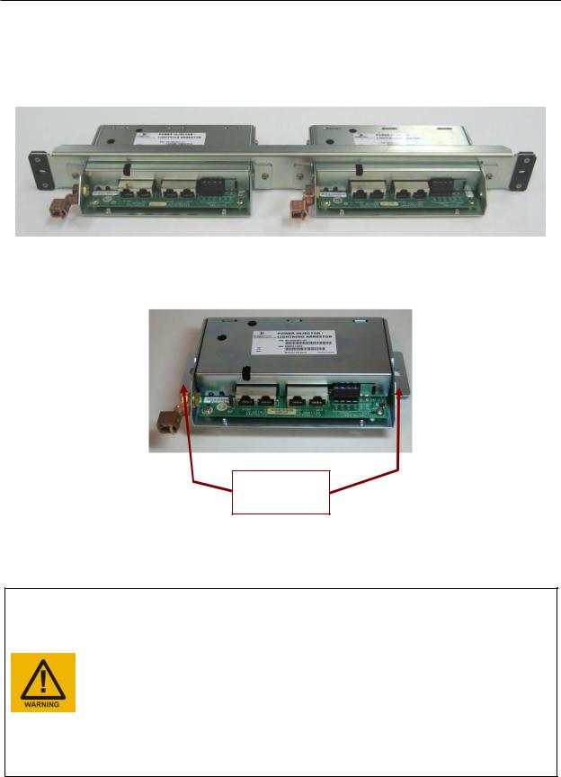
For the Horizon Compact Plus, copper interface variant, protection of the connected network and power supply is provided by a proprietary DragonWave PonE power injector/Lightning Arrestor unit, into which the Ethernet cables and power feed are connected. There are two variants of the copper power injector/Lightning Arrestor unit.
•Copper interface, outdoor use (see Figure 3-3)
omay be mounted on the outside wall of the network equipment building
•Copper interface, indoor use, wall or rack mountable (see Figure 3-4)
omust be mounted inside the network equipment building
Figure 3-3 Outdoor Power injector/Lightning Arrestor
Figure 3-4 Indoor Power injector/Lightning Arrestor
For the Horizon Compact Plus, optical interface variant, or where PonE is not used to power the Horizon, protection of the power feed and the Ethernet connections is provided by a Lightning Arrestor unit of similar physical design to those described above. For correct installation procedures see Section 4.0.
Horizon Compact Plus Release 1.0.1 |
Wireless Ethernet Product User Manual – Volume 1 |
Physical Description
11
3.3Dual Polarization Radio Mount (DPRM)
The DPRM system allows two Horizon Compact Plus units to be assembled to a single antenna. The antenna used is no different to that used for a single unit. One Horizon Compact Plus unit is mounted for horizontal polarization and the other for vertical polarization. Both units can transmit and receive simultaneously. This allows a link to carry up to 800 Mbps of Ethernet traffic. Although both units can operate on the same frequency channels, with 30 dB isolation, it is recommended that different frequency channels be used for each unit.
Figure 3-5 Dual Polarization Radio Mount
3.4Power Split Radio Mount (PSRM)
For redundancy purposes, the PSRM allows two Horizon units to be mounted to a single antenna. Both units must be oriented for the same polarization and only one unit can transmit/receive at any one time. The PSRM looks similar to the DPRM shown in Figure 3-5, but has internal components that only allow one unit to transmit/receive at a time.
Note that redundant systems do not have to use the PSRM. Each may be separately mounted to their own antennas if desired.
The benefits of the PSRM are that only one antenna is required, reducing tower real estate requirements, reducing weight and minimizing wind loading.
Disadvantages include a 4 dB loss in signal when operating on the primary systems at each end of the link and an 8.5 dB loss in signal when a secondary radio is activated (one end running on Primary and other end operating on secondary).
Note that redundancy is not supported in this release.
Horizon Compact Plus Release 1.0.1 |
Wireless Ethernet Product User Manual – Volume 1 |

DragonWave Inc.
12
This page left blank intentionally
Horizon Compact Plus Release 1.0.1 |
Wireless Ethernet Product User Manual – Volume 1 |

4.0 Installation Requirements
Note: For more information on installation and cabling, refer to DragonWave Technical Note: HC-TN-001.4 Horizon Compact Plus PonE.
Various installation kits are available. Use the following key to build the desired kit part number:
CODE |
DESCRIPTION |
INK |
Installation Kit |
R1 |
Horizon Compact Plus Release 1 |
CONNECTOR OPTIONS |
|
HCN |
No Connectors or Cables |
HCC |
Copper Connectors, Out-of-Band Mgmt |
HCI |
Copper Connectors, In-band Mgmt |
HCM |
Military connector, Copper cables |
HCF |
Optical Fibre Interface |
POWER OPTIONS |
|
AC |
Alternating Current |
DC |
Direct Current *** |
AD |
½AC ½DC |
LOCATION OPTIONS |
|
NA |
North America |
EU |
Europe |
GL |
Global |
*** Use ECO #1407 green jumper wire to connect 48V RTN to PonE ground internally when site has grounded 48 VDC return (positive)
Table 4-1 lists all the current ordering configurations, for various parts of the world.
Table 4-1 Parts Required
Kit Description |
|
Part Number |
|
|
|
Horizon Compact Plus, No connectors AC Install Kit (N. America) |
|
A-INK-CPN-AC-NA-R1 |
Horizon Compact Plus, No Connectors AC Install Kit (Europe ) |
|
A-INK-CPN-AC-EU-R1 |
Horizon Compact Plus, No Connectors Half AC, Half DC Install Kit (N. America) |
|
A-INK-CPN-AD-NA-R1 |
Horizon Compact Plus, No Connectors Half AC, Half DC Install Kit (Europe ) |
|
A-INK-CPN-AD-EU-R1 |
Horizon Compact Plus, No Connectors DC Install Kit (Global) |
|
A-INK-CPN-DC-GL-R1 |
|
|
|
Horizon Compact Plus, Rugged No connectors AC Install Kit (N. America) |
|
A-INK-CPNA-AC-NA-R1 |
|
|
|
Horizon Compact Plus, Rugged No Connectors AC Install Kit (Europe ) |
|
A-INK-CPNA-AC-EU-R1 |
|
|
|
Horizon Compact Plus, Rugged No Connectors Half AC, Half DC Install Kit (N. America) |
A-INK-CPNA-AD-NA-R1 |
|
|
|
|
Horizon Compact Plus, Rugged No Connectors Half AC, Half DC Install Kit (Europe ) |
A-INK-CPNA-AD-EU-R1 |
|
|
|
|
Horizon Compact Plus, Rugged No Connectors DC Install Kit (Global) |
|
A-INK-CPNA-DC-GL-R1 |
|
|
|
|
|
|
HC+, Indoor PonE, No connectors AC Install Kit (N. America) |
|
A-INK-CPNI-AC-NA-R1 |
|
|
|
HC+, Indoor PonE, No connectors AC Install Kit (Europe ) |
|
A-INK-CPNI-AC-EU-R1 |
|
|
|
HC+, Indoor PonE, No onnectors DC Install Kit (Global) |
|
A-INK-CPNI-DC-GL-R1 |
|
|
|
|
|
|
HC+, Indoor PonE, Rugged No connectors AC Install Kit (N. America) |
|
A-INK-HNIA-AC-NA-R1 |
|
|
|
HC+, Indoor PonE, Rugged No connectors AC Install Kit (Europe ) |
|
A-INK-HNIA-AC-EU-R1 |
|
|
|
HC+, Indoor PonE, Rugged No onnectors DC Install Kit (Global) |
|
A-INK-HNIA-DC-GL-R1 |
|
|
|
Horizon Compact Plus Release 1.0.1 |
Wireless Ethernet Product User Manual – Volume 1 |
|

DragonWave Inc.
14
|
|
Horizon Compact Plus, Copper Connectors AC Install Kit (N. America) - Includes 4 Glands and 12 |
A-INK-CPC-AC-NA-R1 |
Connectors |
|
Horizon Compact Plus, Copper Connectors AC Install Kit (Europe ) - Includes 4 Glands and 12 |
A-INK-CPC-AC-EU-R1 |
Connectors |
|
Horizon Compact Plus, Copper Connectors Half AC, Half DC Install Kit (N. America) - Includes 4 |
A-INK-CPC-AD-NA-R1 |
Glands and 12 Connectors |
|
Horizon Compact Plus, Copper Connectors Half AC, Half DC Install Kit (Europe ) - Includes 4 |
A-INK-CPC-AD-EU-R1 |
Glands and 12 Connectors |
|
Horizon Compact Plus, Copper Connectors DC Install Kit (Global) - Includes 4 Glands and 12 |
A-INK-CPC-DC-GL-R1 |
Connectors |
|
|
|
Horizon Compact Plus, Copper Connectors, Rugged AC Install Kit (N. America) - Includes 4 Glands |
A-INK-CPCA-AC-NA-R1 |
and 16 Connectors |
|
Horizon Compact Plus, Copper Connectors, Rugged AC Install Kit (Europe ) - Includes 4 Glands |
A-INK-CPCA-AC-EU-R1 |
and 16 Connectors |
|
Horizon Compact Plus, Copper Connectors, Rugged Half AC, Half DC Install Kit (N. America) - |
A-INK-CPCA-AD-NA-R1 |
Includes 4 Glands and 16 Connectors |
|
Horizon Compact Plus, Copper Connectors, Rugged Half AC, Half DC Install Kit (Europe ) - |
A-INK-CPCA-AD-EU-R1 |
Includes 4 Glands and 16 Connectors |
|
Horizon Compact Plus, Copper Connectors, Rugged DC Install Kit (Global) - Includes 4 Glands and |
A-INK-CPCA-DC-GL-R1 |
16 Connectors |
|
|
|
HC+, Indoor PonE, Copper Connectors AC Install Kit (N. America) - Includes 4 Glands and 4 |
A-INK-CPIC-AC-NA-R1 |
Connectors |
|
HC+, Indoor PonE, Copper Connectors AC Install Kit (Europe ) - Includes 4 Glands and 4 |
A-INK-CPIC-AC-EU-R1 |
Connectors |
|
HC+, Indoor PonE, Copper Connectors DC Install Kit (Global) - Includes 4 Glands and 4 |
A-INK-CPIC-DC-GL-R1 |
Connectors |
|
|
|
HC+, Indoor PonE, Copper Connectors, Rugged AC Install Kit (N. America) - Includes 4 Glands and |
A-INK-HICA-AC-NA-R1 |
8 Connectors |
|
HC+, Indoor PonE, Copper Connectors, Rugged AC Install Kit (Europe ) - Includes 4 Glands and 8 |
A-INK-HICA-AC-EU-R1 |
Connectors |
|
HC+, Indoor PonE, Copper Connectors, Rugged DC Install Kit (Global) - Includes 4 Glands and 8 |
A-INK-HICA-DC-GL-R1 |
Connectors |
|
|
|
Horizon Compact Plus, Inband MGMT Copper Connectors AC Install Kit (N. America) - Includes 2 |
A-INK-CPI-AC-NA-R1 |
Glands and 6 Connectors |
|
Horizon Compact Plus, Inband MGMT Copper Connectors AC Install Kit (Europe )- Includes 2 |
A-INK-CPI-AC-EU-R1 |
Glands and 6 Connectors |
|
Horizon Compact Plus, Inband MGMT Copper Connectors Half AC, Half DC Install Kit (N. America) |
A-INK-CPI-AD-NA-R1 |
- Includes 2 Glands and 6 Connectors |
|
Horizon Compact Plus, Inband MGMT Copper Connectors Half AC, Half DC Install Kit (Europe ) - |
A-INK-CPI-AD-EU-R1 |
Includes 2 Glands and 6 Connectors |
|
Horizon Compact Plus, Inband MGMT, Copper Connectors DC Install Kit (Global) - Includes 2 |
A-INK-CPI-DC-GL-R1 |
Glands and 6 Connectors |
|
|
|
Horizon COMPACT PLUS, Inband MGMT Copper Connectors Rugged AC Install Kit (N. America) - |
A-INK-CPIA-AC-NA-R1 |
Includes 2 Glands and 4 Connectors |
|
Horizon Compact Plus, Inband MGMT Copper Connectors Rugged AC Install Kit (Europe )- |
A-INK-CPIA-AC-EU-R1 |
Includes 2 Glands and 4 Connectors |
|
Horizon COMPACT PLUS, Inband MGMT Copper Connectors Rugged Half AC, Half DC Install Kit |
A-INK-CPIA-AD-NA-R1 |
(N. America) - Includes 2 Glands and 4 Connectors |
|
Horizon COMPACT PLUS, Inband MGMT Copper Connectors Rugged Half AC, Half DC Install Kit |
A-INK-CPIA-AD-EU-R1 |
(Europe ) - Includes 2 Glands and 4 Connectors |
|
Horizon COMPACT PLUS, Inband MGMT, Copper Connectors Rugged DC Install Kit (Global) - |
A-INK-CPIA-DC-GL-R1 |
Includes 2 Glands and 4 Connectors |
|
|
|
HC+, Indoor PonE, Inband MGMT Copper Connectors AC Install Kit (N. America) - Includes 2 |
A-INK-CPII-AC-NA-R1 |
Glands and 2 Connectors |
|
HC+, Indoor PonE, Inband MGMT Copper Connectors AC Install Kit (Europe )- Includes 2 Glands |
A-INK-CPII-AC-EU-R1 |
and 2 Connectors |
|
HC+, Indoor PonE, Inband MGMT, Copper Connectors DC Install Kit (Global) - Includes 2 Glands |
A-INK-CPII-DC-GL-R1 |
and 2 Connectors |
|
Horizon Compact Plus Release 1.0.1 |
Wireless Ethernet Product User Manual – Volume 1 |

|
|
Installation Requirements |
|
|
|
15 |
|
|
|
|
|
|
|
||
HC+, Indoor PonE, Inband MGMT Copper Connectors Rugged AC Install Kit (N. America) - Includes |
A-INK-HIIA-AC-NA-R1 |
||
2 Glands and 4 Connectors |
|
|
|
HC+, Indoor PonE, Inband MGMT Copper Connectors Rugged AC Install Kit (Europe )- Includes 2 |
A-INK-HIIA-AC-EU-R1 |
||
Glands and 4 Connectors |
|
|
|
HC+, Indoor PonE, Inband MGMT, Copper Connectors Rugged DC Install Kit (Global) - Includes 2 |
A-INK-HIIA-DC-GL-R1 |
||
Glands and 4 Connectors |
|
|
|
|
|
||
Horizon Compact Plus, Mil Connectors AC Install Kit (N. America) |
A-INK-CPM-AC-NA-R1 |
||
|
|
||
Horizon Compact Plus, Mil Connectors AC Install Kit (Europe ) |
A-INK-CPM-AC-EU-R1 |
||
|
|
||
Horizon Compact Plus, Mil Connectors Half AC, Half DC Install Kit (N. America) |
A-INK-CPM-AD-NA-R1 |
||
|
|
||
Horizon Compact Plus, Mil Connectors Half AC, Half DC Install Kit (Europe ) |
A-INK-CPM-AD-EU-R1 |
||
|
|
||
Horizon Compact Plus, Mil Connectors DC Install Kit (Global) |
A-INK-CPM-DC-GL-R1 |
||
|
|
||
|
|
||
HC+, Indoor PonE, Mil Connectors AC Install Kit (N. America) |
A-INK-CIM-AC-NA-R1 |
||
|
|
||
HC+, Indoor PonE, Mil Connectors AC Install Kit (Europe ) |
A-INK-CIM-AC-EU-R1 |
||
|
|
||
HC+, Indoor PonE, Mil Connectors DC Install Kit (Global) |
A-INK-CIM-DC-GL-R1 |
||
|
|
||
|
|
||
Horizon Compact Plus, Fiber AC Install Kit (N. America) |
A-INK-CPF-AC-NA-R1 |
||
|
|
||
Horizon Compact Plus, Fiber AC Install Kit (Europe ) |
A-INK-CPF-AC-EU-R1 |
||
|
|
||
Horizon Compact Plus, Fiber Half AC, Half DC Install Kit (N. America) |
A-INK-CPF-AD-NA-R1 |
||
|
|
||
Horizon Compact Plus, Fiber Half AC, Half DC Install Kit (Europe ) |
A-INK-CPF-AD-EU-R1 |
||
|
|
||
Horizon Compact Plus, Fiber DC Install Kit (Global) |
A-INK-CPF-DC-GL-R1 |
||
|
|
||
|
|
||
HC+, Indoor PonE, Fiber AC Install Kit (N. America) |
A-INK-CIF-AC-NA-R1 |
||
|
|
||
HC+, Indoor PonE, Fiber AC Install Kit (Europe ) |
A-INK-CIF-AC-EU-R1 |
||
|
|
||
HC+, Indoor PonE, Fiber DC Install Kit (Global) |
A-INK-CIF-DC-GL-R1 |
||
|
|
||
|
|
||
INST KIT,HALF LINK,Horizon Compact Plus,NO CONN,AC,N.A.,R1 |
AH-INK-CPN-AC-NA-R1 |
||
|
|
||
INST KIT,HALF LINK,Horizon Compact Plus,NO CONN,DC,GLOBAL,R1 |
AH-INK-CPN-DC-GL-R1 |
||
|
|
||
|
|
||
INST KIT,HALF LINK,Horizon Compact Plus,Rugged NO CONN,AC,N.A.,R1 |
AH-INK-CPNA-AC-NA-R1 |
||
|
|
||
INST KIT,HALF LINK,Horizon Compact Plus,Rugged NO CONN,DC,GLOBAL,R1 |
AH-INK-CPNA-DC-GL-R1 |
||
|
|
||
|
|
||
INST KIT,HALF LINK,Horizon Compact Plus,COPPER CONN,AC,N.A.,R1 |
AH-INK-CPC-AC-NA-R1 |
||
|
|
||
INST KIT,HALF LINK,Horizon Compact Plus,COPPER CONN,DC,GLOBAL,R1 |
AH-INK-CPC-DC-GL-R1 |
||
|
|
||
INST KIT,HALF LINK,HC+ INDOOR PonE,COPPER CONN,DC,GLOBAL,R1 |
AH-INK-CIC-DC-GL-R1 |
||
|
|
||
|
|
||
INST KIT,HALF LINK,HC+ INDOOR PonE,FIBER,AC,N.A.,R1) |
AH-INK-CIF-AC-NA-R1 |
||
|
|
||
INST KIT,HALF LINK,HC+ INDOOR PonE,FIBER,AC,EU,R1 |
AH-INK-CIF-AC-EU-R1 |
||
|
|
||
INST KIT,HALF LINK,HC+ INDOOR PonE,FIBER,DC,GLOBAL,R1 |
AH-INK-CIF-DC-GL-R1 |
||
|
|
||
INST KIT,HALF LINK,HC+,MIL CONN,AC,N.A.,R1 |
AH-INK-CPM-AC-NA-R1 |
||
|
|
||
INST KIT,HALF LINK,HC+,MIL CONN,DC,GLOBAL,R1 |
AH-INK-CPM-DC-GL-R1 |
||
|
|
||
INST KIT,HALF LINK,HC+,FIBER,AC,N.A.,R1 |
AH-INK-CPF-AC-NA-R1 |
||
|
|
||
INST KIT,HALF LINK,HC+,FIBER,DC,GLOBAL,R1 |
AH-INK-CPF-DC-GL-R1 |
||
|
|
||
INST KIT,HALF LINK,HC+, Indoor PonE, Mil Connectors AC Install Kit (N. America) |
AH-INK-CIM-AC-NA-R1 |
||
|
|
||
INST KIT,HALF LINK,HC+, Indoor PonE, Mil Connectors AC Install Kit (Europe ) |
AH-INK-CIM-AC-EU-R1 |
||
|
|
||
INST KIT,HALF LINK,HC+, Indoor PonE, Mil Connectors DC Install Kit (Global) |
AH-INK-CIM-DC-GL-R1 |
||
|
|
|
|
Horizon Compact Plus Release 1.0.1 |
Wireless Ethernet Product User Manual – Volume 1 |

DragonWave Inc.
16
4.1Lightning Arrestor Units
The importance of protecting network and power systems from damaging voltage transients, induced by lightning and other sources, cannot be over emphasized.
DragonWave supplies four types of Lightning Arrestor Units.
•Outdoor rated Lightning Arrestor with integrated power on Ethernet (PonE)
•Indoor rated Lightning Arrestor with integrated power on Ethernet (PonE)
•Outdoor rated Lightning Arrestor only
•Indoor rated Lightning Arrestor only
All four provide protection for up to two Ethernet network cables plus redundant power feeds.
4.1.1Outdoor Lightning Arrestor Units
The Outdoor units are housed in a weatherproof plastic enclosure employing gland nut seals for cable entry. Access to network and power terminals is via a gasket sealed lid, which is secured by four retaining screws. Figure 4-1 shows the Lightning Arrestor unit with integrated PonE, with lid removed.
Figure 4-1 Outdoor Lightning Arrestor Unit with Integrated PonE Supply Feed
4.1.2Indoor Lightning Arrestor Units
The Indoor units are housed in a metal enclosure with an integral grounding lug and with direct access to network and power connection terminations.
Figure 4-2 Indoor Lightning Arrestor Unit with Integrated PonE Supply Feed
Horizon Compact Plus Release 1.0.1 |
Wireless Ethernet Product User Manual – Volume 1 |
Installation Requirements
17
Mounting systems for the indoor units include a 19” rack mounting adapter, which accommodates up to two units within a 1U rack space, and wall mount brackets, allowing a single unit to be wall, or shelf, mounted as required (screw slots will accommodate 6mm (1/4”) diameter screws on 7.2” centres, horizontally).
Figure 4-3 Two Indoor Units in Rack Mount Adapter
Wall mounting brackets are removable
Figure 4-4 Indoor Unit with Wall Mount Brackets
Rack/cabinet in which Indoor units are installed must only be used for the purposes of housing lightning suppression equipment.
Rack/cabinet must be equipped, grounded and bonded for lightning suppression purposes.
Rack/cabinet must meet all local electrical and safety codes
Rack/cabinet must be certified by a qualified safety/lightning engineer.
DO NOT connect the grounding lug to AC power supply wiring ground!
DO NOT mix AC power supply option with site-supplied 48 VDC!
DO NOT connect the network to the RJ45 connectors marked
“TO HORIZON UNPROTECTED”. Damage to switches or routers may result
Horizon Compact Plus Release 1.0.1 |
Wireless Ethernet Product User Manual – Volume 1 |
DragonWave Inc.
18
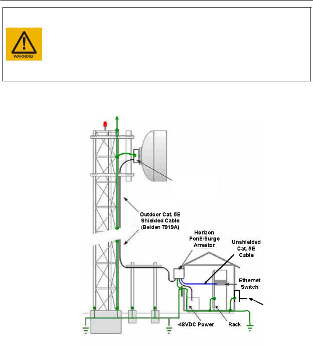
DO NOT mount the PonE unit to the tower!
The Outdoor rated PonE Injector/Lightning Arrestor MUST be mounted as close as possible to, and above, the building entry point (BEP) and its external grounding lug must be connected to the nearest lightning (LPS) ground with #6 AWG (minimum) grounding wire, avoiding loops and sharp bends.
DO NOT connect the grounding lug to AC power supply wiring ground! DO NOT mix AC power supply option with site-supplied 48 VDC!
DO NOT connect the network to the RJ45 connectors marked
“TO HORIZON UNPROTECTED”. Damage to switches or routers may result
Horizon
Compact
Plus
BEPconnect tower ground to shack ground
Power feed to shack
Figure 4-5 Horizon Compact Plus Installation
Horizon Compact Plus Release 1.0.1 |
Wireless Ethernet Product User Manual – Volume 1 |

Installation Requirements
19
4.2Grounded Power Feeds
Where the return side of a site-supplied power feed is grounded, provision is made on all versions of the lightning arrestor units to link the return feed to the integral grounding lug on the unit. A shorting link is stored on J4. When grounding is required, this is transferred to J5 (see Figure 4-6).
Shorting link is stored on J4 and transferred to J5, as shown, when grounding is required
Figure 4-6 Grounded Power Return Link
On earlier models of both the indoor and outdoor lightning arrestors, the shorting link feature is not present. To ground the return side of the power supply for the earlier models, connect a shorting wire between the “RTN” connection on the power connection block and the grounding point on the PCB as shown in Figure 4-7.
Figure 4-7 Grounded Power Return Shorting Wire
Horizon Compact Plus Release 1.0.1 |
Wireless Ethernet Product User Manual – Volume 1 |

DragonWave Inc.
20
4.3Ethernet Cabling – Copper Interface
DO NOT coil excess Ethernet cable, but fold in a zig-zag fashion whilst observing a minimum bend radius of 2 inches. The effect of lightning induced current surges in the tower or conductors adjacent to the Ethernet cable will be minimized when the Ethernet cable is folded in this way.
For the copper interface, data cabling from the Horizon Compact Plus unit to the PonE Power Injector/Lightning Arrestor consists of outdoor rated, shielded, CAT5E cables equivalent to Belden 7919A. The shielded cables require shielded RJ45 connectors. Use of standard indoor unshielded RJ45 connectors may result in a lack of lightning protection, poorly constructed cables, intermittent connections and data loss. Depending on the system configuration ordered and fielded, up to four shielded RJ45 and two unshielded RJ45 connectors are provided.
The cables terminate in a DWI Power on Ethernet (PonE) Power Injector/Lightning Arrestor unit located either outside of the building cable entry point (using the outdoor PonE unit) or inside the network equipment building (using the indoor PonE unit).
DO NOT CONNECT SHIELDED RJ45 CONNECTORS TO ETHERNET CABLES CONNECTING THE LIGHTNING ARRESTOR TO THE NETWORK SWITCH.
Note: Straight through Ethernet cables must be used between the PonE power injector and the Horizon Compact Plus. The use of a cross-over type, or incorrectly wired CAT5E cables, will cause the PonE power injector to go into an alarm condition and not power up the Horizon Compact Plus. A Status LED indicates the status of the PonE power injector (see Section 5.1.4)
The PonE unit contains Lightning Arrestors and must be grounded according to local or regional Electrical Codes. Unshielded Ethernet cables are connected between the PonE unit and the Ethernet switch or router. Power for the PonE unit is supplied by 2-wire 16 AWG electrical wiring, carrying 48 V DC (-48 V or +48 V) with a maximum current draw of 2 amperes.
If Port 2 is not being used, ensure that a protective weatherproof cap is fitted to the port receptacle.
4.3.1Using Outdoor PonE Unit
Figure 4-8 Outdoor Unit PonE and RJ45 Connections
Horizon Compact Plus Release 1.0.1 |
Wireless Ethernet Product User Manual – Volume 1 |
 Loading...