

Page 1

Harmony Lite, R1.1
Product Description
Revision 1, Updated in September, 2014
Document Number: PM-000157-01-EN
Page 2

NOTICE
This document contains DragonWave proprietary information. Use, disclosure,
copying or distribution of any part of the information contained herein, beyond that
for which it was originally furnished, requires the written permission of
DragonWave Inc.
The information in this document is subject to change without notice and relates
only to the product defined in the introduction of this document. DragonWave
intends that information contained herein is, to the best of its knowledge, correct
and accurate. However, any/all liabilities associated with the use or accuracy of
the information contained herein must be defined in a separate agreement
between DragonWave and the custom er /u ser .
Copyright © DragonWave Inc. 2014. All rights reserved.
2
Page 3

Table of Contents
Table of Contents . . . . . . . . . . . . . . . . . . . . . . . . . . . . . . . . . . . . . . . . . . 3
1 Preface . . . . . . . . . . . . . . . . . . . . . . . . . . . . . . . . . . . . . . . . . . . . . . . . . . 9
1.1 What’s New in This Release? . . . . . . . . . . . . . . . . . . . . . . . . . . . . . . . . . 9
1.2 Changes History . . . . . . . . . . . . . . . . . . . . . . . . . . . . . . . . . . . . . . . . . . . 9
1.3 Scope of The Document . . . . . . . . . . . . . . . . . . . . . . . . . . . . . . . . . . . . . 9
1.4 Intended Audience. . . . . . . . . . . . . . . . . . . . . . . . . . . . . . . . . . . . . . . . . . 9
1.5 FCC & IC RF Exposure Warnings . . . . . . . . . . . . . . . . . . . . . . . . . . . . . . 9
1.6 Waste Electrical and Electronic Equipment (WEEE). . . . . . . . . . . . . . . 10
1.7 RoHS Compliance . . . . . . . . . . . . . . . . . . . . . . . . . . . . . . . . . . . . . . . . . 10
1.8 CE Statement . . . . . . . . . . . . . . . . . . . . . . . . . . . . . . . . . . . . . . . . . . . . 11
2 Overview . . . . . . . . . . . . . . . . . . . . . . . . . . . . . . . . . . . . . . . . . . . . . . . . 12
2.1 Available Bandwidth and Modulation. . . . . . . . . . . . . . . . . . . . . . . . . . . 13
2.2 Applications . . . . . . . . . . . . . . . . . . . . . . . . . . . . . . . . . . . . . . . . . . . . . . 13
2.2.1 Small Cell Backhaul in Non-line-of-sight (NLOS) Environment . . . . . . . 13
2.2.2 Rural Backhaul . . . . . . . . . . . . . . . . . . . . . . . . . . . . . . . . . . . . . . . . . . . 14
2.2.3 Public Safety and Vertical Applications . . . . . . . . . . . . . . . . . . . . . . . . . 14
2.3 Environmental Standards . . . . . . . . . . . . . . . . . . . . . . . . . . . . . . . . . . . 14
3 Features. . . . . . . . . . . . . . . . . . . . . . . . . . . . . . . . . . . . . . . . . . . . . . . . . 15
3.1 Main Features . . . . . . . . . . . . . . . . . . . . . . . . . . . . . . . . . . . . . . . . . . . . 15
3.2 Adaptive Coding and Modulation (ACM) . . . . . . . . . . . . . . . . . . . . . . . . 15
3.3 Transmit Power Control (TPC). . . . . . . . . . . . . . . . . . . . . . . . . . . . . . . . 16
3.4 2x2 Multiple-input and Multiple-output (2x2 MIMO). . . . . . . . . . . . . . . . 16
3.5 Dynamic Frequency Selection (DFS). . . . . . . . . . . . . . . . . . . . . . . . . . . 17
3.6 Dynamic Channel Selection (DCS) . . . . . . . . . . . . . . . . . . . . . . . . . . . . 17
3.7 Retransmission . . . . . . . . . . . . . . . . . . . . . . . . . . . . . . . . . . . . . . . . . . . 18
3.8 Configurable Uplink/Downlink Ratio. . . . . . . . . . . . . . . . . . . . . . . . . . . . 19
3.9 Quality of Service (QoS) . . . . . . . . . . . . . . . . . . . . . . . . . . . . . . . . . . . . 20
3.9.1 Priority Determination (Classification) . . . . . . . . . . . . . . . . . . . . . . . . . . 20
3.9.2 Scheduling. . . . . . . . . . . . . . . . . . . . . . . . . . . . . . . . . . . . . . . . . . . . . . . 20
3.9.3 CoS Queue and Egress Port Rate Limiting (Shaping). . . . . . . . . . . . . . 22
3.10 Power over Ethernet . . . . . . . . . . . . . . . . . . . . . . . . . . . . . . . . . . . . . . . 22
3.10.1 P+E . . . . . . . . . . . . . . . . . . . . . . . . . . . . . . . . . . . . . . . . . . . . . . . . . . . . 22
3.10.2 PoE+ . . . . . . . . . . . . . . . . . . . . . . . . . . . . . . . . . . . . . . . . . . . . . . . . . . . 23
3.11 Synchronization . . . . . . . . . . . . . . . . . . . . . . . . . . . . . . . . . . . . . . . . . . . 25
3.12 Co-site Synchronization. . . . . . . . . . . . . . . . . . . . . . . . . . . . . . . . . . . . . 26
3.13 OFDM Modulation . . . . . . . . . . . . . . . . . . . . . . . . . . . . . . . . . . . . . . . . . 28
3.14 Low-density Parity Check (LDPC) Encoding . . . . . . . . . . . . . . . . . . . . . 29
3.15 LLDP . . . . . . . . . . . . . . . . . . . . . . . . . . . . . . . . . . . . . . . . . . . . . . . . . . . 30
3.16 Radio Port Performance Monitoring. . . . . . . . . . . . . . . . . . . . . . . . . . . . 31
3.17 Adaptive Noise Immunity (ANI) . . . . . . . . . . . . . . . . . . . . . . . . . . . . . . . 31
4 Mechanical Structure and Interfaces . . . . . . . . . . . . . . . . . . . . . . . . . . . 32
4.1 Dimensions and Weight. . . . . . . . . . . . . . . . . . . . . . . . . . . . . . . . . . . . . 32
4.2 Interfaces. . . . . . . . . . . . . . . . . . . . . . . . . . . . . . . . . . . . . . . . . . . . . . . . 32
3
Page 4

4.2.1 P+E In (Eth 1) Interface . . . . . . . . . . . . . . . . . . . . . . . . . . . . . . . . . . . . . 34
4.2.2 P+E Out (Eth 2) Interface . . . . . . . . . . . . . . . . . . . . . . . . . . . . . . . . . . . . 35
4.2.3 PoE+ In Interface (optional) . . . . . . . . . . . . . . . . . . . . . . . . . . . . . . . . . . 36
4.2.4 Internal Interface (optional). . . . . . . . . . . . . . . . . . . . . . . . . . . . . . . . . . . 37
4.2.5 RF Interface (optional) . . . . . . . . . . . . . . . . . . . . . . . . . . . . . . . . . . . . . . 38
4.2.6 RSSI/EVM Interface . . . . . . . . . . . . . . . . . . . . . . . . . . . . . . . . . . . . . . . . 38
5 Product Structure . . . . . . . . . . . . . . . . . . . . . . . . . . . . . . . . . . . . . . . . . . 40
5.1 Packet Processing Module . . . . . . . . . . . . . . . . . . . . . . . . . . . . . . . . . . . 40
5.2 Power Supply Module. . . . . . . . . . . . . . . . . . . . . . . . . . . . . . . . . . . . . . . 41
5.3 IEEE 1588v2 Module . . . . . . . . . . . . . . . . . . . . . . . . . . . . . . . . . . . . . . . 41
5.4 Baseband and RF Module . . . . . . . . . . . . . . . . . . . . . . . . . . . . . . . . . . . 41
5.5 Antenna. . . . . . . . . . . . . . . . . . . . . . . . . . . . . . . . . . . . . . . . . . . . . . . . . . 41
6 Management. . . . . . . . . . . . . . . . . . . . . . . . . . . . . . . . . . . . . . . . . . . . . . 42
6.1 Web-based GUI (Link Viewer) Management . . . . . . . . . . . . . . . . . . . . . 42
6.2 Accessing . . . . . . . . . . . . . . . . . . . . . . . . . . . . . . . . . . . . . . . . . . . . . . . . 42
6.3 SNMP Agent. . . . . . . . . . . . . . . . . . . . . . . . . . . . . . . . . . . . . . . . . . . . . . 42
6.4 SNTP, SFTP and SSH . . . . . . . . . . . . . . . . . . . . . . . . . . . . . . . . . . . . . . 42
6.5 Software Upgrade. . . . . . . . . . . . . . . . . . . . . . . . . . . . . . . . . . . . . . . . . . 43
6.6 License . . . . . . . . . . . . . . . . . . . . . . . . . . . . . . . . . . . . . . . . . . . . . . . . . . 43
7 Technical Specification. . . . . . . . . . . . . . . . . . . . . . . . . . . . . . . . . . . . . . 45
7.1 Regulation Compliance. . . . . . . . . . . . . . . . . . . . . . . . . . . . . . . . . . . . . . 45
7.2 Radio Performance. . . . . . . . . . . . . . . . . . . . . . . . . . . . . . . . . . . . . . . . . 47
7.3 Ethernet Throughput. . . . . . . . . . . . . . . . . . . . . . . . . . . . . . . . . . . . . . . . 49
7.4 Latency . . . . . . . . . . . . . . . . . . . . . . . . . . . . . . . . . . . . . . . . . . . . . . . . . . 60
8 Standards . . . . . . . . . . . . . . . . . . . . . . . . . . . . . . . . . . . . . . . . . . . . . . . . 66
4
Page 5

List of Figures
Figure 1 WEEE Label . . . . . . . . . . . . . . . . . . . . . . . . . . . . . . . . . . . . . . . . . . . . . 10
Figure 2 CE Mark. . . . . . . . . . . . . . . . . . . . . . . . . . . . . . . . . . . . . . . . . . . . . . . . . 11
Figure 3 Equipment Appearance . . . . . . . . . . . . . . . . . . . . . . . . . . . . . . . . . . . . . 12
Figure 4 NLOS Application . . . . . . . . . . . . . . . . . . . . . . . . . . . . . . . . . . . . . . . . . 14
Figure 5 ACM for Traffic Growing . . . . . . . . . . . . . . . . . . . . . . . . . . . . . . . . . . . . 15
Figure 6 TPC Design . . . . . . . . . . . . . . . . . . . . . . . . . . . . . . . . . . . . . . . . . . . . . . 16
Figure 7 QoS Architecture . . . . . . . . . . . . . . . . . . . . . . . . . . . . . . . . . . . . . . . . . . 20
Figure 8 P+E functionality . . . . . . . . . . . . . . . . . . . . . . . . . . . . . . . . . . . . . . . . . . 22
Figure 9 Power Feeding Two Lites with P+E PSE Equipment at A Chain Site . . 23
Figure 10 PoE+ functionality schema . . . . . . . . . . . . . . . . . . . . . . . . . . . . . . . . . . 23
Figure 11 Power Feeding Two Lites Using PoE+ Equipment at A Chain Site. . . . 24
Figure 12 Co-site Synchronization Realization . . . . . . . . . . . . . . . . . . . . . . . . . . . 26
Figure 13 Co-site Synchronization Mechanism . . . . . . . . . . . . . . . . . . . . . . . . . . . 27
Figure 14 PoE+/P+E Interfaces . . . . . . . . . . . . . . . . . . . . . . . . . . . . . . . . . . . . . . . 32
Figure 15 P+E Interfaces. . . . . . . . . . . . . . . . . . . . . . . . . . . . . . . . . . . . . . . . . . . . 33
Figure 16 Lite With Box Cover. . . . . . . . . . . . . . . . . . . . . . . . . . . . . . . . . . . . . . . . 34
Figure 17 Function modules of Lite . . . . . . . . . . . . . . . . . . . . . . . . . . . . . . . . . . . . 40
5
Page 6

List of Tables
Table 1 Changes History . . . . . . . . . . . . . . . . . . . . . . . . . . . . . . . . . . . . . . . . . . . . 9
Table 2 FCC & IC RF Recommended Safe Separation Distances . . . . . . . . . . . 10
Table 3 SP Queues Configuration. . . . . . . . . . . . . . . . . . . . . . . . . . . . . . . . . . . . 21
Table 4 Dimensions and Weight . . . . . . . . . . . . . . . . . . . . . . . . . . . . . . . . . . . . . 32
Table 5 P+E In. . . . . . . . . . . . . . . . . . . . . . . . . . . . . . . . . . . . . . . . . . . . . . . . . . . 34
Table 6 Pinout Definition of P+E In . . . . . . . . . . . . . . . . . . . . . . . . . . . . . . . . . . . 35
Table 7 P+E Out . . . . . . . . . . . . . . . . . . . . . . . . . . . . . . . . . . . . . . . . . . . . . . . . . 35
Table 8 Pinout Definition of P+E Out. . . . . . . . . . . . . . . . . . . . . . . . . . . . . . . . . . 36
Table 9 PoE+ In. . . . . . . . . . . . . . . . . . . . . . . . . . . . . . . . . . . . . . . . . . . . . . . . . . 36
Table 10 Pinout Definition of PoE+ In . . . . . . . . . . . . . . . . . . . . . . . . . . . . . . . . . . 37
Table 11 Internal . . . . . . . . . . . . . . . . . . . . . . . . . . . . . . . . . . . . . . . . . . . . . . . . . . 37
Table 12 Pinout Definition of Internal. . . . . . . . . . . . . . . . . . . . . . . . . . . . . . . . . . . 38
Table 13 RSSI/EVM parameters . . . . . . . . . . . . . . . . . . . . . . . . . . . . . . . . . . . . . . 39
Table 14 5 GHz . . . . . . . . . . . . . . . . . . . . . . . . . . . . . . . . . . . . . . . . . . . . . . . . . . . 45
Table 15 3 GHz . . . . . . . . . . . . . . . . . . . . . . . . . . . . . . . . . . . . . . . . . . . . . . . . . . . 45
Table 16 2 GHz . . . . . . . . . . . . . . . . . . . . . . . . . . . . . . . . . . . . . . . . . . . . . . . . . . . 46
Table 17 5 GHz Radio Performance . . . . . . . . . . . . . . . . . . . . . . . . . . . . . . . . . . . 47
Table 18 3 GHz Radio Performance . . . . . . . . . . . . . . . . . . . . . . . . . . . . . . . . . . . 47
Table 19 2 GHz Radio Performance . . . . . . . . . . . . . . . . . . . . . . . . . . . . . . . . . . . 48
Table 20 MCS table. . . . . . . . . . . . . . . . . . . . . . . . . . . . . . . . . . . . . . . . . . . . . . . . 49
Table 21 Ethernet L1 Throughput of 50/50 Tx/Rx Ratio (40 MHz/GI:400 ns) . . . . 49
Table 22 Ethernet L1 throughput of 50/50 Tx/Rx ratio (40 MHz/ GI:800 ns) . . . . . 49
Table 23 Ethernet L1 throughput of 50/50 Tx/Rx ratio (20 MHz/ GI:400 ns) . . . . . 50
Table 24 Ethernet L1 throughput of 50/50 Tx/Rx ratio (20 MHz/ GI:800 ns) . . . . . 50
Table 25 Ethernet L2 throughput of 50/50 Tx/Rx ratio (40 MHz/ GI:400 ns) . . . . . 51
Table 26 Ethernet L2 throughput of 50/50 Tx/Rx ratio (40 MHz/ GI:800 ns) . . . . . 51
Table 27 Ethernet L2 throughput of 50/50 Tx/Rx ratio (20 MHz/ GI:400 ns) . . . . . 51
Table 28 Ethernet L2 throughput of 50/50 Tx/Rx ratio (20 MHz/ GI:800 ns) . . . . . 52
Table 29 Ethernet L1 Tx throughput of 70/30 Tx/Rx ratio (40 MHz/ GI:400 ns) . . 52
Table 30 Ethernet L1 Rx throughput of 70/30 Tx/Rx ratio (40 MHz/ GI:400 ns) . . 53
Table 31 Ethernet L1 Tx throughput of 70/30 Tx/Rx ratio (40 MHz/ GI:800 ns) . . 53
Table 32 Ethernet L1 Rx throughput of 70/30 Tx/Rx ratio (40 MHz/ GI:800 ns) . . 54
Table 33 Ethernet L1 Tx throughput of 70/30 Tx/Rx ratio (20 MHz/ GI:400 ns) . . 54
Table 34 Ethernet L1 Rx throughput of 70/30 Tx/Rx ratio (20 MHz/ GI:400 ns) . . 55
Table 35 Ethernet L1 Tx throughput of 70/30 Tx/Rx ratio (20 MHz/ GI:800 ns) . . 55
Table 36 Ethernet L1 Rx throughput of 70/30 Tx/Rx ratio (20 MHz/ GI:800 ns) . . 56
Table 37 Ethernet L2 Tx throughput of 70/30 Tx/Rx ratio (40 MHz/ GI:400 ns) . . 56
Table 38 Ethernet L2 Rx throughput of 70/30 Tx/Rx ratio (40 MHz/ GI:400 ns) . . 57
Table 39 Ethernet L2 Tx throughput of 70/30 Tx/Rx ratio (40 MHz/ GI:800 ns) . . 57
Table 40 Ethernet L2 Rx throughput of 70/30 Tx/Rx ratio (40 MHz/ GI:800 ns) . . 58
Table 41 Ethernet L2 Tx throughput of 70/30 Tx/Rx ratio (20 MHz/ GI:400 ns) . . 58
Table 42 Ethernet L2 Rx throughput of 70/30 Tx/Rx ratio (20 MHz/ GI:400 ns) . . 59
Table 43 Ethernet L2 Tx throughput of 70/30 Tx/Rx ratio (20 MHz/ GI:800 ns) . . 59
Table 44 Ethernet L2 Rx throughput of 70/30 Tx/Rx ratio (20 MHz/ GI:800 ns) . . 60
Table 45 Latency - 50/50 Tx/Rx Ratio 40 MHz/GI:400 ns . . . . . . . . . . . . . . . . . . . 60
6
Page 7

Table 46 Latency - 50/50 Tx/Rx Ratio 40 MHz/GI:800 ns . . . . . . . . . . . . . . . . . . 61
Table 47 Latency - 50/50 Tx/Rx Ratio 20 MHz/GI:400 ns . . . . . . . . . . . . . . . . . . 61
Table 48 Latency - 50/50 Tx/Rx Ratio 20 MHz/GI:800 ns . . . . . . . . . . . . . . . . . . 61
Table 49 Latency - 70/30 Tx/Rx Ratio 40 MHz/GI:400 ns . . . . . . . . . . . . . . . . . . 62
Table 50 Latency - 70/30 Tx/Rx Ratio 40 MHz/GI:800 ns . . . . . . . . . . . . . . . . . . 62
Table 51 Latency - 70/30 Tx/Rx Ratio 20 MHz/GI:400 ns . . . . . . . . . . . . . . . . . . 63
Table 52 Latency - 70/30 Tx/Rx Ratio 20 MHz/GI:800 ns . . . . . . . . . . . . . . . . . . 63
Table 53 Latency - 30/70 Tx/Rx Ratio 40 MHz/GI:400 ns . . . . . . . . . . . . . . . . . . 63
Table 54 Latency - 30/70 Tx/Rx Ratio 40 MHz/GI:800 ns . . . . . . . . . . . . . . . . . . 64
Table 55 Latency - 30/70 Tx/Rx Ratio 20 MHz/GI:400 ns . . . . . . . . . . . . . . . . . . 64
Table 56 Latency - 30/70 Tx/Rx Ratio 20 MHz/GI:800 ns . . . . . . . . . . . . . . . . . . 65
Table 57 IEEE Standards . . . . . . . . . . . . . . . . . . . . . . . . . . . . . . . . . . . . . . . . . . . 66
Table 58 CEPT standards . . . . . . . . . . . . . . . . . . . . . . . . . . . . . . . . . . . . . . . . . . 66
Table 59 ETSI Standards . . . . . . . . . . . . . . . . . . . . . . . . . . . . . . . . . . . . . . . . . . . 67
Table 60 ITUT Standards . . . . . . . . . . . . . . . . . . . . . . . . . . . . . . . . . . . . . . . . . . . 68
Table 61 IEC Standards . . . . . . . . . . . . . . . . . . . . . . . . . . . . . . . . . . . . . . . . . . . . 68
Table 62 NEBS Standards . . . . . . . . . . . . . . . . . . . . . . . . . . . . . . . . . . . . . . . . . . 68
Table 63 FCC Standards . . . . . . . . . . . . . . . . . . . . . . . . . . . . . . . . . . . . . . . . . . . 68
Table 64 ICES Standards. . . . . . . . . . . . . . . . . . . . . . . . . . . . . . . . . . . . . . . . . . . 69
Table 65 UL Standards. . . . . . . . . . . . . . . . . . . . . . . . . . . . . . . . . . . . . . . . . . . . . 69
Table 66 ECC Standards . . . . . . . . . . . . . . . . . . . . . . . . . . . . . . . . . . . . . . . . . . . 69
Table 67 IC Standards . . . . . . . . . . . . . . . . . . . . . . . . . . . . . . . . . . . . . . . . . . . . . 69
7
Page 8

8
Page 9

DragonWave Inc. Preface
1Preface
1.1 What’s New in This Release?
• 3 GHz support;
• Tx/Rx ratio: 70/30;
• Co-site synchronization;
• PM of radio interface;
• LLDP.
1.2 Changes History
The changes history is shown below:
Revision Updates Update date
1 1st revision. September, 2014
Table 1 Changes History
1.3 Scope of The Document
This document provides the technical description and the technical specifications of
Harmony Lite (also referred to as Lite in the following context) system.
g
This document only concerns Lite system release 1.1 without specific statements in the
context.
1.4 Intended Audience
This document is intended for the radio network planners and technicians who are
responsible for the system planning and management.
f
f
Persons handling this equipment may be exposed to hazards which could result in
physical injury! It is therefore mandatory to carefully read and understand this document.
This is the text in French:
Les personnes qui manipulent cet équipement peuvent être exposés à des risques q ui
pourraient entraîner des blessures graves! il est donc impératif de lire attentivement et
de comprendre ce document.
1.5 FCC & IC RF Exposure Warnings
To satisfy FCC & IC RF exposure requirements for RF transmitting devices, the following distances should be maintained between the antenna of this device and persons
during device operation:
9
Page 10

DragonWave Inc.Preface
Equipment Separation Distance
Lite 5 GHz 39.03 cm (~ 15.37 in) or more
Lite 3 GHz 80.40 cm (~ 31.51 in) or more
Table 2 FCC & IC RF Recommended Safe Separation Distances
To ensure compliance, operation at closer than these distances is not recommended.
The antenna used for this transmitter must not be collocated in conjunction with any
other antenna or transmitter.
1.6 Waste Electrical and Electronic Equipment (WEEE)
All waste electrical and electronic products must be disposed of separately from the
municipal waste stream via designated collection facilities appointed by the government
or the local authorities. The WEEE label (see Figure 1) is applied to all such devices.
Figure 1 WEEE Label
The correct disposal and separate collection of waste equipment will help prevent poten-
tial negative consequences for the environment and human health. It is a precondition
for reuse and recycling of used electrical and electronic equipment.
For more detailed information about disposal of such equipment, please contact DragonWave Inc.
The above statements are fully valid only for equipment installed in the countries o f the
European Union and is covered by the directive 2002/96/EC. Countries outside the
European Union may have other regulatio ns re gar din g th e disp o sa l of electrical and
electronic equipment.
1.7 RoHS Compliance
This product complies with the European Union RoHS Directive 2011/65/EU on the
restriction of use of certain hazardou s substances in electrical and electronic equipment.
The directive applies to the use of lead, mercury, cadmium, hexavalent chromium, polybrominated biphenyls (PBB), and polybrominated diphenylethers (PBDE) in electrical
and electronic equipment put on the market after 1 July 2006.
Materials usage information on DragonWave Inc. Electronic Information Products
imported or sold in the People’s Republic of China
This product complies with the Chinese standard SJ/T 11364-2006 on the restriction of
the use of certain hazardous substances in electrical and electronic equipment. The
standard applies to the use of lead, mercury, cadmium, hexavalent chromium, polybro-
10
Page 11

DragonWave Inc. Preface
minated biphenyls (PBB), and polyb rominated diphenyl ethers (PBDE) in electrical and
electronic equipment put on the market after 1 March 2007.
1.8 CE Statement
The CE conformity declaration for the product is fulfilled when the system is built and
cabled in line with the information given in the manual and the docume ntation specified
within it, such as installation instructions, cable lists or the like. Where necessary projectspecific documentation should be taken into consideration. Deviations from the specifications or independent modifications to the layout, such as use of cable types with lower
screening values for example, can lead to violation of the CE protection requirements.
In such cases the conformity declaration is invalidated. The responsibility for any
problems which subsequently arise rests with the party responsible for deviating from
the installation specifications.
Figure 2 CE Mark
11
Page 12

DragonWave Inc.Overview
2Overview
Lite is a complete sub-6 GHz microwave system housed within a single outdoor weatherproof enclosure. The system has standard Ethernet interfaces and the antenna can
be integrated or separated. The system is an integrated, zoning-friendly, packet micro wave solution, optimized for the urban environment.
Figure 3 Equipment Appearance
Lite provides a host of benefits, including:
• Non-line-of-sight (NLOS) support across both licensed and unlicensed TDD spectrum;
• Complete scalability, supporting 20/40 MHz channel bandwidth;
• Advanced interference avoidance features including site synchronization;
• Flexible network architecture options.
In addition, Lite has the following advantages:
• support of adaptive coding and modulation (ACM);
• support of transition power control (TCP);
• support of 2x2 multiple-input and multiple-output (2x2 MIMO);
• support of dynamic frequency selection (DFS);
• support of dynamic channel selection (DCS);
• support of retransmission;
• support of configurable uplink/downlink ratio;
• support of QoS (advanced quality of service with 8 queues);
• support of power over Ethernet (P+E, PoE+);
• support of synchronization;
• support of co-site synchronization;
• support of OFDM modulation;
• support of low-density parity check (LDPC) encoding;
• software upgradable to support SyncE and 1588v2 transparent clock;
• support of up to 230 Mbit/s aggregate capacity;
• support of small cell optimized backhaul for NLOS applications;
• performance with very low delay;
• support of licensed or unlicensed spectrum;
• requirement of simple installation as an integrated outd oo r unit;
12
Page 13

DragonWave Inc. Overview
• requirement of minimized footprint and power consumption (under 17 W) with green
design;
• support of adaptive noise immunity (ANI).
2.1 Available Bandwidth and Modulation
Lite product family supports the following frequency bands:
• 4.9 ~ 5.8 GHz (5 GHz);
• 3.4 ~ 3.8 GHz (3 GHz);
• 2.3 ~ 2.7 GHz (2 GHz).
Lite supports modulation schema BPSK, QPSK, 16 QAM and forwards error correction
coding with rates of 1/2, 2/3, 3/4 and 5/6. 20 MHz and 40 MHz channel spacings are
supported. See 7.2.
2.2 Applications
2.2.1 Small Cell Backhaul in Non-line-of-sight (NLOS) Environment
Many types of radio transmission depend, to varying degrees, on line of sight (LOS)
between the transmitter and receiver. Small cell backhaul is changing this rule of g ame.
Most small cells are installed of light poles of on the walls of buildings in urban areas and
inevitably encounter obstructions such as trees, street curves and buildings between the
endpoints of the backhaul links.The non-line-of-sight (NLOS) capability of Lite ideally
suites itself in this environment because it operates at the frequency lower than 6 GHz.
Furthermore, by supporting both licen se d an d un licen s ed spe ctr u m, Lite allo ws ope ra tors to select a spectrum strategy that best meets their requirements.
This wireless backhaul solution delivers significant total cost of ownership (TCO)
improvements over existing macro-cell backhaul solutions, allowing operato rs to expand
their networks cost-effectively.
Lite can be deployed using a tree topology (Figure 4), with macro-cell traffic aggregation
points on rooftops, and tail, chain or small hub microsites at street level. This architecture provides:
• Less network interference than point-to-multipoint system due to the use of directive
antennas;
• Simple network connectivity and reliable path planning.
• An evolution path towards protected network architecture.
13
Page 14

Figure 4 NLOS Application
DragonWave Inc.Overview
2.2.2 Rural Backhaul
The need for extending cellular phone and data network to rural areas requires a
backhaul solution that achieves the lowest TCO while meeting the stringent link throughput and distance requirements. Lite provides a cost-effective solution that supports long
ling-of-sight distance (> 20 km) using licensed and unlicensed frequency bands and
achieves high throughput and low latency.
2.2.3 Public Safety and Vertical Applications
Lite can also be used to build secure, reliable and cost effective transport for first
responders (police, fire and medical), video surveillance and sensor network backhauling along motorways, sea ports, electricity grid, oil and gas pipelines and border security
fence, etc.
2.3 Environmental Standards
In normal operation condition, the working temperature range for Lite is from -40 ºC to
+55 ºC. For the detailed information, refer to the document of Environmental Product
Declaration.
14
Page 15

DragonWave Inc. Features
3Features
3.1 Main Features
Lite embraces the following features:
• Adaptive Coding and Modulation (ACM)
• Transmit Power Control (TPC)
• 2x2 Multiple-input and Multiple-output (2x2 MIMO)
• Dynamic Frequency Selection (DFS)
• Dynamic Channel Selection (DCS)
• Retransmission
• Configurable Uplink/Downlink Ratio
• Quality of Service (QoS)
• Power over Ethernet
• Synchronization
• Co-site Synchronization
• OFDM Modulation
• Low-density Parity Check (LDPC) Encoding
• LLDP
• Radio Port Performance Monitoring
• Adaptive Noise Immunity (ANI)
3.2 Adaptive Coding and Modulation (ACM)
ACM allows the user to improve link utilization by making high capacity data transmission reliable. ACM changes code and modulation according to the link quality in the
same channel bandwidth.
Figure 5 ACM for Traffic Growing
ACM refers to the automatic modulation adjustment that a wireless system can perform
to prevent weather related fading from disrupting communication on the link.
When server weather condition, such as a heavy rain, affects the transmission and
reception of data over a wireless network, the radio system automatically changes the
modulation, so that non-real-time data-based applications may be affected by signal
degradation, but real-time applications will run smoothly and continuously.
Since communication signals are modulated, higher modulation levels increase the
number of bits that are transferred per signal, thus enablin g higher throughputs, or better
spectral efficiencies. It should be noted that, when using a higher modu lation technique,
better signal-to-noise ratios (SNR) are needed to overcome interference and ma intain a
tolerable bit error ratio (BER) level.
15
Page 16

Lite measures the receiving signal quality by calculating the receiving EVM at any time.
ACM allows the system to choose the best modulation in order to overcome fading and
other interference.
The algorithm uses the highest possible modulation in accordance with link quality degradation.
The switch between modulation depends on the re ceiv ing s ign al qu a lity.
For example, on a clear day, using 64 QAM modulation, the transmit and receive data
capacity can be 120 Mbit/s. When the weather becomes over cast and stormy, the ACM
algorithm changes the modulation to 32 QAM and the system transmits at 100 Mbit/s.
Switchover has the ability to step up or down through all the modulation schemes
between BPSK and 64 QAM. This guarantees that the link will operate at the highest
possible modulation scheme at any time.
3.3 Transmit Power Control (TPC)
TPC controls the far-end transmit power level in order to keep the r eceived signa l level
above a certain user-defined threshold, in accordance with the particular modulation
method and capacity being used.
TPC allows traffic to transmit at a low power level while enough SNR is maintained. It is
a green design which reduces the interference to other system and power con sumption.
DragonWave Inc.Features
Figure 6 TPC Design
User can define target power for the local site and Lite will measure the difference
between the RSSI and target power, and feedback to remote site so that th e remote site
can adjust the transmit power accordingly.
TPC feature provides the customer with more flexibility in network design.
3.4 2x2 Multiple-input and Multiple-output (2x2 MIMO)
In radio, MIMO is the use of multiple antennas at both the transmitter and receiver to
improve communication performance. It is one of several forms of smart antenna technology.
MIMO technology offers significant increases in data throughput without additional
bandwidth. It achieves this goal by spreading the same total transmit power over the
antennas to achieve an array gain that improves the spectral efficiency (more bits per
second per hertz of bandwidth) or to achieve a diversity gain ghat improves the li nk reliability.
By using a dual polarized (cross polarization) antenna, Lite supports 2x2 MIMO with a
single antenna.
16
Page 17

DragonWave Inc. Features
3.5 Dynamic Frequency Selection (DFS)
Radar detection is required when Lite operates on channels that have a nominal bandwidth falling partly, or completely, within the frequency range from 5250 MHz to 53 50
MHz, or 5470 MHz to 5725 MHz.
Furthermore, Lite does not share the channel with other de vice, so beside radar signal,
once Lite detected other equipment operating on the same channel, it will automatically
switch to another channel.
Lite implements DFS according to EN 301 893, EN 302 502, FCC 47CFR part 15 operating as a master.
Accordingly, the operational behavior and individual DFS requirement that are associated with Lite are as follows:
• At installation (or re-installation), it is assumed to have no available channels within
the 5250 MHz to 5350 MHz band and/or the 5470 MHz and 5725 MHz band. In such
a case, before starting operations on one of those channels, the equipment perfor ms
a channel availability check (CAC) to ensure that there is no radar operating on the
channel. If no radar has been detected, the channel becomes an available channel
and remains as is until a radar signal is detected during the in-service monitoring.
There will be no transmissions by Lite within the channel being checked during this
process.
• Once Lite has started operations on an available channel, that channel becomes th e
operating channel. During normal operation, the operating channel will be monitored
(in-service monitoring) to ensure that there is no radar operating on the channel.
• If a radar signal or signal from other device is detected dur ing in-service monitoring,
Lite devices in the link will stop transmitting on this channel which becomes an
unavailable channel.
• An unavailable channel becomes a usable channel after the n on-occupancy period.
A new CAC is required to verify that there is no radar operating on the channel,
before it may be used again. If no radar is detected, the channel becomes an available channel once again.
3.6 Dynamic Channel Selection (DCS)
Besides DFS required by regulation, Lite also implements DCS to dynamically select the
working channel according to the interference level, because the interference from cochannel and adjacent channels may affect the performance of Lite.
• Spectrum scan
Before occupying a channel, Lite must scan the current band and select the best
channel as the operation channel.
After the spectrum scan, Lite will give a graphic report of the interference level of
each 20 MHz channel.
• In-service monitoring
After occupying a channel, Lite executes in-service monitoring to detect if there is
interference from co-channel or adjacent channel.
By monitoring the errors on the physical layer, Lite can count the PHY error, channel
utilization ratio and packet error rate to determine whether to change to another
channel.
17
Page 18

• Channel shutdown
When interference signal detected in operation channel exceeds the threshold, Lite
will notify the remote site and switch to another channel.
3.7 Retransmission
At unlicensed frequency band, especially in urban areas, the interference is not predictable due to the complicated and dynamically changing environment. The sporad ic burst
of interference may result in packet loss (defective packet is also dropped by the
receiver).
Lite implements dynamic packet retransmission mechanism by which the corrupted or
lost packet is retransmitted until it is received correctly or the timeout reaches.
The retransmission function implements a negative ackn owledgement (NACK) method.
The receiver explicitly notifies the sender when packets, messages, or segments were
received incorrectly and thus may need to be retransmitted, and the transmitter will
buffer the recent transmitted packets and retransmit the requested packets.
DragonWave Inc.Features
18
Page 19

DragonWave Inc. Features
3.8 Configurable Uplink/Downlink Ratio
To meet the different market data model requirements, Lite supports configurable
uplink/downlink ratio to better utilize the radio bandwidth.
Lite downlink/uplink ratio can be set to 50:50, 70:30 or 30:70 which can improve the
bandwidth utilization for different scenarios. E.g., uplink and downlink traffic are not
usually balanced, the download traffic usually being much more than the uplink traffic.
In this case, 30:70 ratio can be used to improve bandwidth utilization.
19
Page 20

3.9 Quality of Service (QoS)
Figure 7 shows the QoS architecture of Lite with the following main components.
• Priority determination (classification)
• Scheduling
• CoS queue and egress port rate limiting (shaping).
DragonWave Inc.Features
Figure 7 QoS Architecture
3.9.1 Priority Determination (Classification)
Lite supports service priority determination based on the 802.1p byte/DSCP. Dependin g
on the priority determination of the data, the system will direct the data into different
queues.
3.9.2 Scheduling
Lite supports 8 queues on each port, each queue corresponding to one priority, from the
highest CoS7 to the lowest CoS0. The following scheduling methods are supported by
Lite:
• Strict priority (SP)
The SP mothod schedules access to the egress port between the QoS queues, from
the highest QoS queue index to the lowest. The purpose is to provide a lower latency
service to the higher QoS class of traffic.
Traffic in higher priority queues is scheduled first until all demand is met or until all
available bandwidth is used.
Strict priority queues have no limit or CIR so it will get all the bandwidth required if it
is available, before bandwidth is offered to other queues.
20
Page 21

DragonWave Inc. Features
• Weighted round robin (WRR)
WRR is used to allocate a bandwidth per queue to ensu re that each queue gets th e
amount of bandwidth determined by the weighing assigned.
The available bandwidth is distributed to the queues in need of bandwidth proportional to the assigned weight.
Once every WRR minimum bandwidth per queue has been satisfied, excess bandwidth is allocated in proportion to the weights of the queues competing for the
excess bandwidth.
The weight of each queue can be configurable from 1 to 127.
• Deficit Weighted Round Robin (DWRR)
An inherent limitation of WRR mode is that the actual bandwidth allocated to a
queue depends on the frame size, but as frame sizes are not known to the scheduler, it is hard to control the bandwidth allocated to a queue.
To address this issue, DWRR is invented. It is a modified version of WRR.
DWRR has two parameters, credit counter (also called deficit counter) and quantum.
DWRR serves the frames at the head of every non-empty queue whose credit
counter is greater than the frame’s size. If the credit counter is lower, the queue is
skipped and its credit is increased by a given value called quantum. Hence, the
function of quantum is somewhat like weight but is in bytes. This increased value is
used to calculate the credit counter the next time around when the scheduler
examines this queue for serving its head-of-line frame. If the queue is served, the
credit is decremented by the size of frame being served.
• SP + WRR/DWRR
The combination of SP and WRR/DWRR method is supported. In this method, a
certain number of CoS queues (out of 8) on an egress por t work in SP mode , while
the rest of the queues on the same port work in WRR/DWRR mode. it is possible to
enable all CoS queues either in SP or WRR/DWRR mode, or some with SP and the
rest with WRR/DWRR. However, the queues configured for SP mode must have a
higher index value than those for WRR/DWRR mode. The SP mode iindices must
also be consecutive.
Up to 8 queues (starting from Q8) can be configured for strict priority queues (see
Table 3). SP queues use SP based on CoS values to assign bandwidth ahead of
other WRR or DWRR queues.
Number of SP Queues Configured Corresponding SP Queues
1Q8
2Q7, Q8
3 Q6, Q7, Q8
4 Q5, Q6, Q7, Q8
5 Q4, Q5, Q6, Q7, Q8
6 Q3, Q4, Q5, Q6, Q7, Q8
7 Q2,Q3, Q4, Q5, Q6, Q7, Q8
8 Q1, Q2,Q3, Q4, Q5, Q6, Q7, Q8
Table 3 SP Queues Configuration
21
Page 22
3.9.3 CoS Queue and Egress Port Rate Limiting (Shaping)
Traffic shaping is supported across each egress port.
Lite supports port rate limiting by L1 and L2.
3.10 Power over Ethernet
To be size/cost optimized, there is no dedicated external power supply interface to Lite.
The power supply feed to Lite is provided over Ethernet interface.
Both standard PoE+ (IEEE 802.3at) and P+E solutions are supported.
DragonWave Inc.Features
g
Lite is available in 2 hardware versions, one supporting both PoE+ and P+E, another
supporting only P+E. Refer to 4.2 for the mechanism. Refer to the document of Order
Codes Reference for the order codes of the 2 versions.
The system’s rated voltage is -48 VDC, rated current 1.0 A.
P+E is a proprietary power over Ethernet solution that supports at least 60 W of power
output. Lite also supports one P+E output which facilitates powering an additional Lite.
The PoE+ and P+E circuits are independent.
3.10.1 P+E
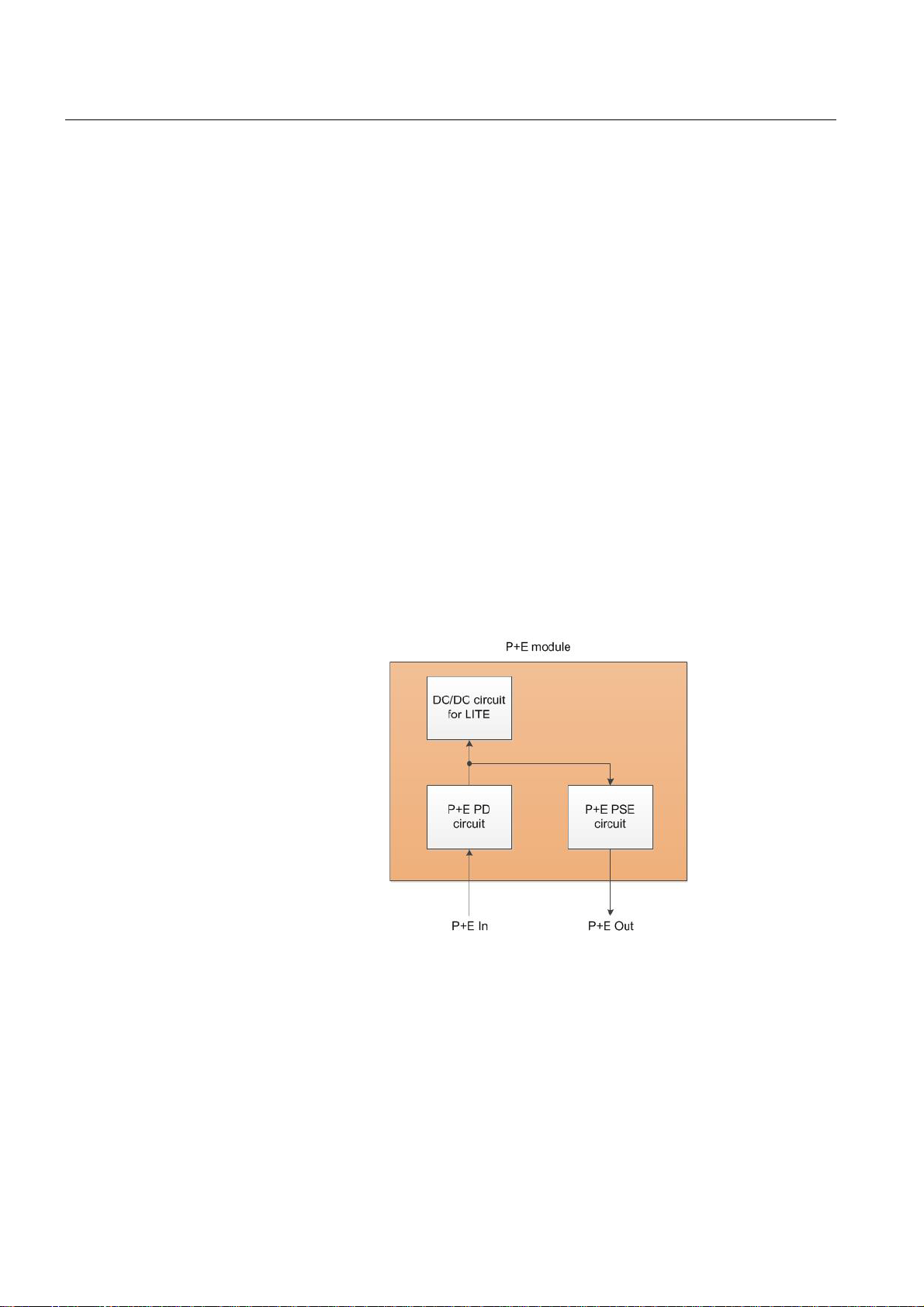
The functionality of the P+E feature is shown is Figure 8.
22
Figure 8 P+E functionality
• The P+E In interface works as a P+E PD (powered device) port. Lite can be fed by
a P+E PSE (power source equipment) via this port. This interface can be connected
to the following systems:
– IDU such as Hub 800 (with order code T555800M B.0 1) or First Mile 200 i;
– AC/DC or DC/DC proprietary Power Injector;
– Base station with P+E functionality.
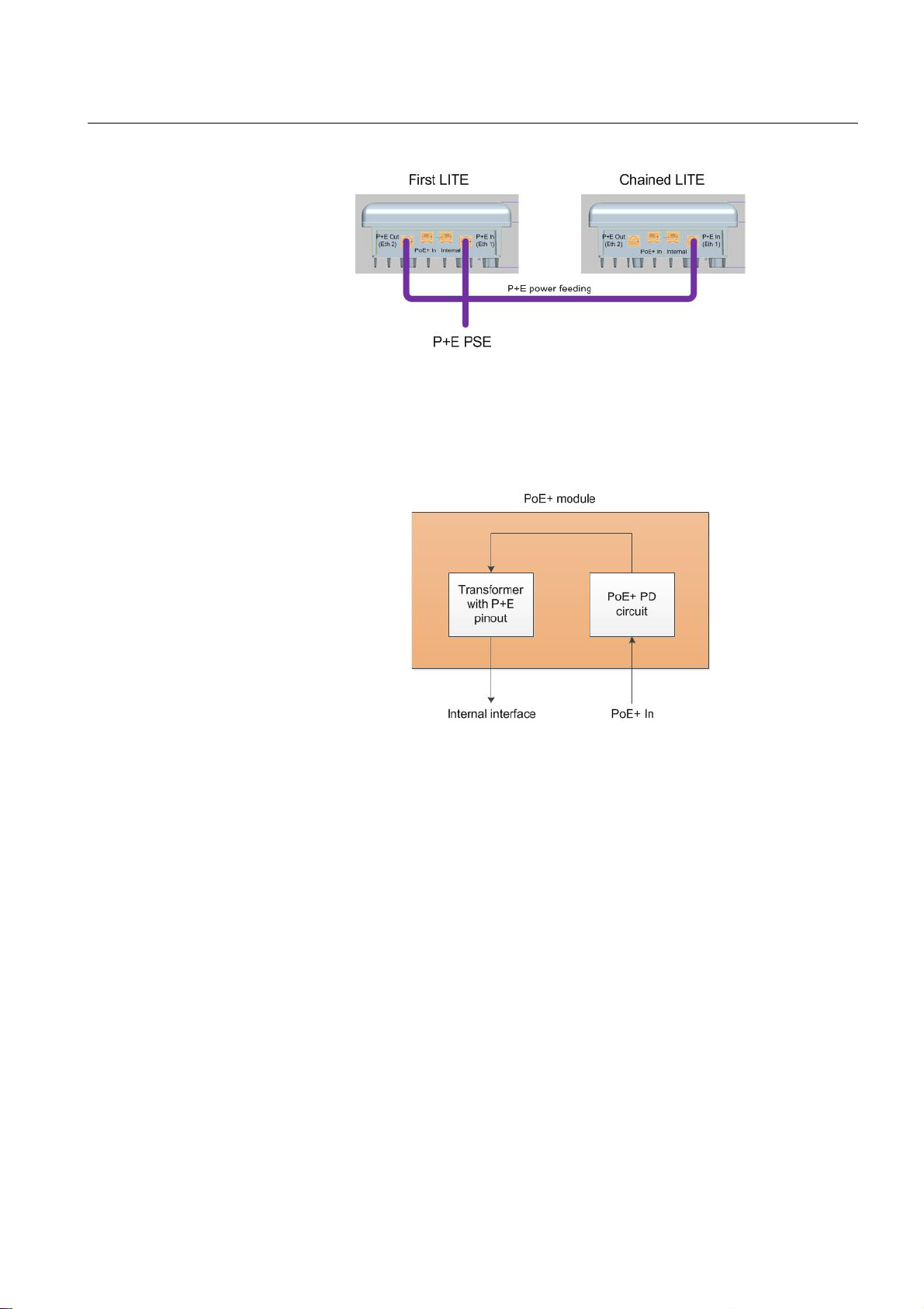
• The P+E Out interface works as P+E PSE port and can be used to feed another Lite
at the same location (chain site).
Figure 9 shows the scenario where a P+E device is powering two Lites.
Page 23
DragonWave Inc. Features
Figure 9 Power Feeding Two Lites with P+E PSE Equipment at A Chain Site
3.10.2 PoE+
The functionality of the PoE+ feature is shown in Figure 10.
Figure 10 PoE+ functionality schema
• The PoE+ In interface works as a PoE + PD por t. Lite can be powered by a standard
PoE+ PSE via this port. This interface can be connected to the following systems:
– Generic IDU that uses PoE+ modality;
– Base station with PoE+ functionality
– PoE+ Power Injector.
• The Internal interface is a port with P+E po wer pinout. This port transfers power and
Ethernet traffic between PoE+ In and P+E In interfaces.
• The P+E Out interface works as P+E PSE port and can be used to feed another Lite
at the same location (chain site).
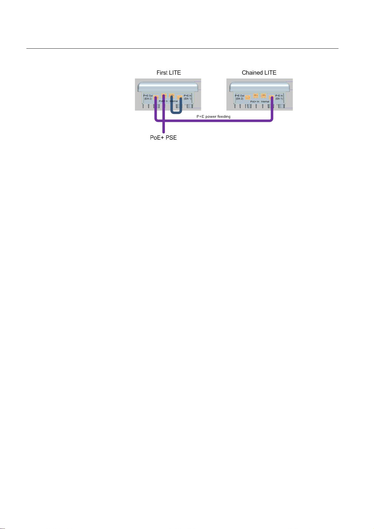
At a chain site, two Lites can be powered from a single PoE+ PSE power feed. Figure
11 shows the scenario where a PoE+ device is powering two Lites.
23
Page 24
DragonWave Inc.Features
Figure 11 Power Feeding Two Lites Using PoE+ Equipment at A Chain Site
24
Page 25

DragonWave Inc. Features
3.11 Synchronization
Sync Ethernet is supported on both Ethernet interfaces.
Lite can also deliver synchronization and timing across the radio when RF interface is
selected as timing source.
TDD RF is naturally unfriendly to synchronization and timing delivery, Lite can achieve
synchronization quality close to physical timing based on proprietary time stamping
mechanism.
25
Page 26
3.12 Co-site Synchronization
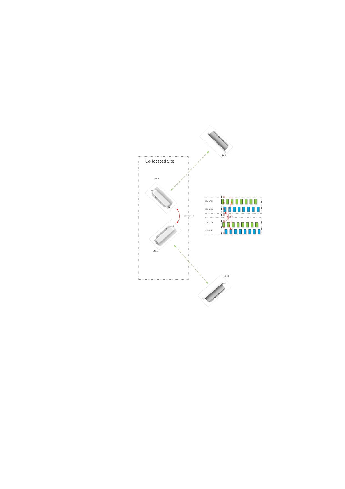
To better reuse the frequency and reduce the interference of co-site imple mentation, cosite synchronization is implemented.
When two collocated Lites who use the sa me frequency or frequency close to each other
are not synchronized and one of them is in transmitting status and another one is receiving status, the receiving Lite will receive the remote site signal plus the transmitting Lite’s
interference signal, which results in packet loss or even link breakdown.
DragonWave Inc.Features
26
Figure 12 Co-site Synchronization Realization
Co-site synchronization is used to control all links connected to the same node to
transmit and receive at the same time, thus transmitting ov er receiving interfer ence can
be avoided. Site synchronization is achieved through in-band protocol on GE interfaces
without any need for GPS signal and/or dedicated distribution.
A 1588-like mechanism is employed to synchronize the transmission trigger. One Lite
at the hub site is assigned the role of master an d the rest co-site Lites are assigned
slave. The 1588-like protocol synchronizes the transmitting and receiving time and
interval so the Lite in the same site can switch to transmit or to receive at the same time
to avoid any site receiving the signal from the collocated Lite.
When the co-site synchronization is enabled, the Tx/Rx cycle will be aligned so the local
Tx will not interfere with the collocated Rx.
Page 27

DragonWave Inc. Features
Figure 13 Co-site Synchronization Mechanism
27
Page 28

3.13 OFDM Modulation
The PHY block of Lite is a half-duplexed OFDM baseband processor which supports 52
sub-carrier in 20 MHz bandwidth and 114 sub-carrier in 40 MHz bandwidth which allows
the system to have high spectral efficiency while have robust performance against
narrow-band interference and frequency-selective fading due to multi-path.
Configurable GI allows Lite to work in different scenarios to combat with different delay
spread. The short GI configuration allows Lite to work in low delay spread condition to
have better throughput while the long GI configuration allows Lite to have better radio
performance in worse delay spread condition by sacrificing the throughput.
DragonWave Inc.Features
28
Page 29

DragonWave Inc. Features
3.14 Low-density Parity Check (LDPC) Encoding
Lite implies LDPC as the FEC coding method which can correct bit error during transmission. It allows the system to survive in poor SNR scenario. In the same SNR scenario, it may allow the system to work in higher modulation scheme or have a better
packet error performance.
Lite supports 1/2, 2/3, 3/4, 5/6 LDPC encoding combined with different modulation
schemes, to meet different SNR and through pu t re qu ire m ent.
29
Page 30

3.15 LLDP
LLDP is supported to advertise the system key capabilities on the Ethernet LAN and also
learn the key capabilities of other systems on the same Ethernet LAN. Information like
system name and description, IP management address, etc., can be sent or received as
LLDPDU (LLDP data unit) via SNMP MIB for every station to know their neighbors,
LLDP frames are sent at a fixed rate on each port of every station and no acknowledgement is expected from the receiver. It is so-called one way connectionless data link layer
protocol which runs on MAC layer.
LLDP allows the NMS to build the physical topology of the network under its supervision.
The NMS can only get a complete picture of the controlled network when all the NEs
support LLDP.
Both Single-IDU mode and Dual-IDU mode support LLDP.
For detailed information about LLDP, refer to IEEE 802.1 ABTM-2005.
DragonWave Inc.Features
30
Page 31

DragonWave Inc. Features
3.16 Radio Port Performance Monitoring
Lite provides sophisticated performance monitoring method to allow customer to
monitor its working status, e.g.,
• Tx/Rx power statistics do the Tx/Rx monitoring and the attenuation cha nge information collection;
• EVM statistics do the link quality monitoring;
• Link available time adds up the working time of the link;
• Packet error statistics do the packet error calculation in both real time and history,
allowing the customer to understand the impact of link quality degradation;
• Interference statistics do the co-channel interference and off-channel interference
calculation in both real time and history to help the customer make man ual operation
when it is needed.
3.17 Adaptive Noise Immunity (ANI)
5 GHz unlicensed band often operates in challenging environment with many different
sources of interference, compromising the performance of Lite.
Many system can operate in the same frequency band, such as WLAN devices, wireless
cameras and microwave ovens. This may have significant influence on Lite. By activating Adaptive Noise Immunity, Lite ignores sources of interference in the radio fie l d and
only focuses on remote Lite with sufficient signal strength. This process is based on
measured values of the link with regard to interferences in the radio field. If a defined
threshold is exceeded, the reception sensitivity of Lite will be reduced respectively.
Therefore, the probability is increased that the system will ignore interferences while
searching for a free transmission slot. These adaptive changes of the reception sensitivity are based on the permanent check of the radio field.
31
Page 32
4 Mechanical Structure and Interfaces
4.1 Dimensions and Weight
The following table lists the dimensions and weight of the equipment.
Item Value
Height 218 mm
Width 223 mm
Depth 97.0 mm (with 190x190 mm integrated antenna )
94.5 mm (with box cover for external antenna)
DragonWave Inc.Mechanical Structure and Interfaces
Weight (without daughter card or
cables)
Table 4 Dimensions and Weight
4.2 Interfaces
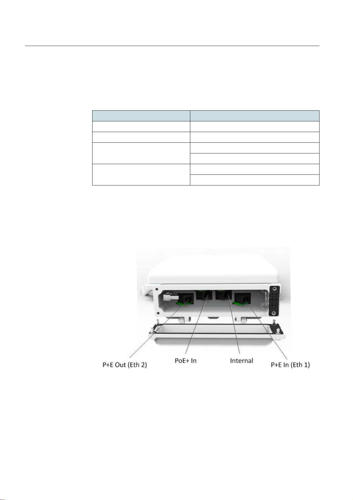
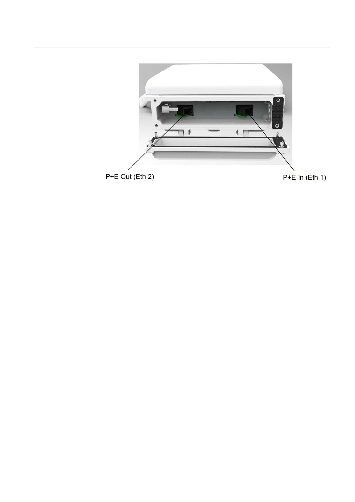
Lite is a compact system with two versions, PoE+/P+E version (Figure 14) and P+E
version (Figure 15).
1.80 Kg (with 190x190 mm integrated antenna)
2.03 Kg (with box cover for external antenna)
32
Figure 14 PoE+/P+E Interfaces
Page 33
DragonWave Inc. Mechanical Structure and Interfaces
Figure 15 P+E Interfaces
The PoE+/P+E version supports both PoE+ and P+E feeding method, but not in the
same time. It embeds 4 interfaces, whose functions will be introduced in the following
text.
The P+E version supports only P+E feeding method. It embeds 2 interfaces, whose
functions will be introduced in the following text.
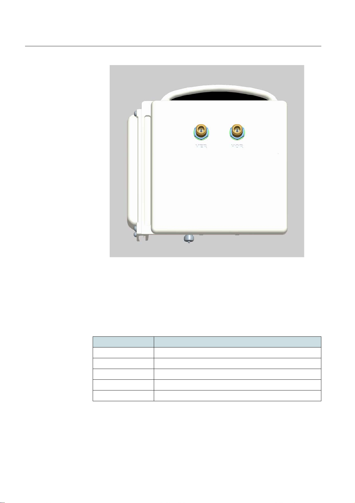
Lite has two deployments, one is with an integrated antenna, the other is with a box
cover (Figure 16) to co-work with an external antenna.
33
Page 34
DragonWave Inc.Mechanical Structure and Interfaces
Figure 16 Lite With Box Cover
The main connectors are all enclosed in the weatherproof compartment, having a
hinged lid with a weather seal. The grounding point locates on the back.
4.2.1 P+E In (Eth 1) Interface
This is a P+E PD interface which can be connected to an IDU’s power sourcing equipment port or a collocated Lite’s power sourcing equipment port.
Property Description
Interface type 100/1000 Base-T
Duplex mode half and full with auto-negotiation or manual
Rate 100/1000 Mbit/s with auto-negotiation
MDI type auto sensing MDI/MDIX or manual
Front panel reference P+E IN (ETH 1)
Table 5 P+E In
34
Page 35
DragonWave Inc. Mechanical Structure and Interfaces
Property Description
Connector type
Suggested cable Shielded twisted pair (STP cat5e), at least 24 AWG wire
Power supply Works as P+E PD port. Lite can be fed by P+E PSE via this
Table 5 P+E In
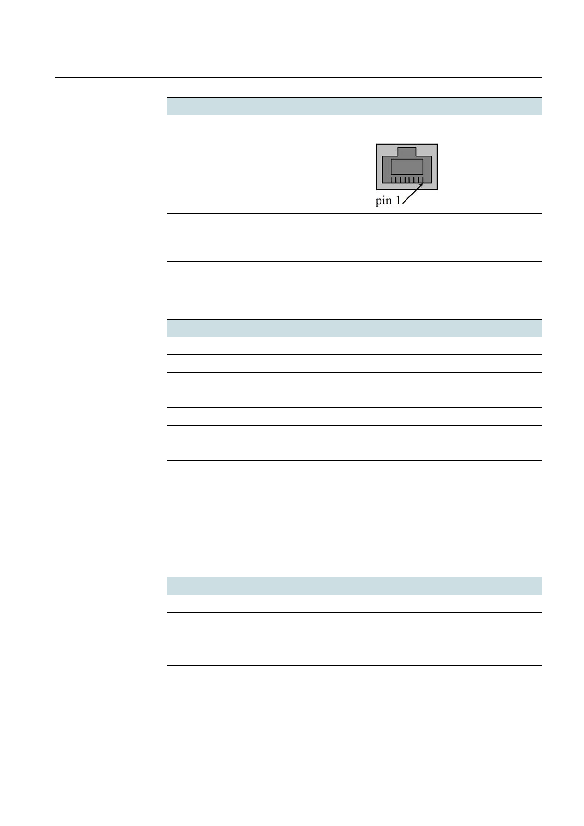
The pinout definition is shown in the following table.
Pin Number Pin Function Power Pinout
1 pair A+ negative
2 pair A- negative
3 pair B+ negative
4 pair C+ positive
Shielded GE RJ45 8 pin gold plated contacts.
port.
5 pair C- positive
6 pair B- negative
7 pair D+ positive
8 pair D- positive
Table 6 Pinout Definition of P+E In
4.2.2 P+E Out (Eth 2) Interface
This is a P+E PSE interface which can be used to connect with collocated Lite at the
chain site. This interface can also be used for troubleshooting and installation in field.
Property Description
Interface type 100/1000 Base-T
Duplex mode half and full with auto-negotiation or manual
Rate 100/1000 Mbit/s with auto-negotiation
MDI type auto sensing MDI/MDIX or manual
Front panel reference P+E OUT (ETH 2)
Table 7 P+E Out
35
Page 36
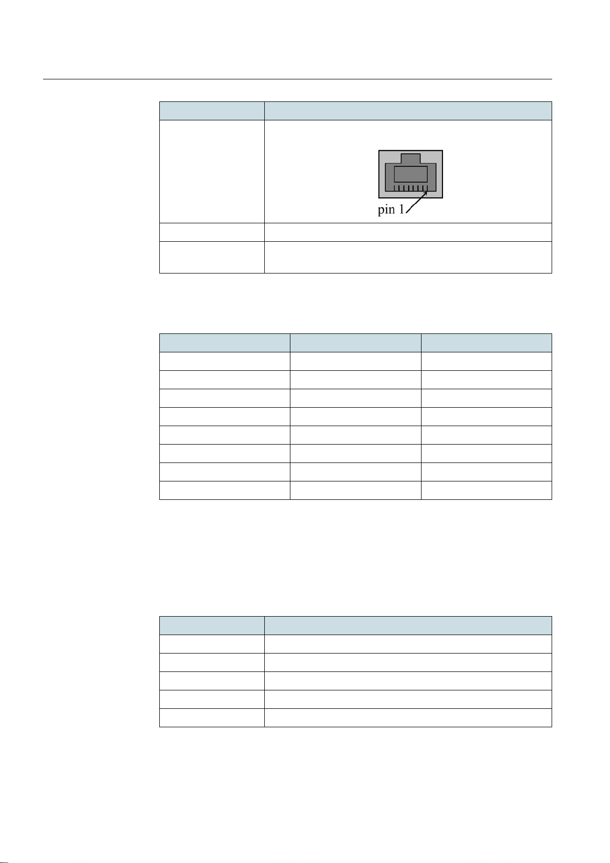
Property Description
DragonWave Inc.Mechanical Structure and Interfaces
Connector type
Suggested cable Shielded twisted pair (STP cat5e), at least 24 AWG wire
Power supply Works as P+E PSE port. It can feed to the second Lite at a
Table 7 P+E Out
The pinout definition is shown in the following table.
Pin Number Pin Function Power Pinout
1 pair A+ negative
2 pair A- negative
3 pair B+ negative
4pair C+positive
Shielded GE RJ45 8 pin gold plated contacts.
chain site.
5pair C-positive
6 pair B- negative
7pair D+positive
8pair D-positive
Table 8 Pinout Definition of P+E Out
4.2.3 PoE+ In Interface (optional)
The optional PoE+ In interface is located with the Internal interface on the PoE+ module,
which is only required in the PoE+ application. The PoE+ In interface is a PoE+ PD port
that can be connected with an IDU which can work as PoE+ PSE.
Property Description
Interface type 100/1000 Base-T
Duplex mode half and full with auto-negotiation or manual
Rate 100/1000 Mbit/s with auto-negotiation
MDI type auto sensing MDI/MDIX or manual
Front panel reference PoE+ IN
36
Table 9 PoE+ In
Page 37
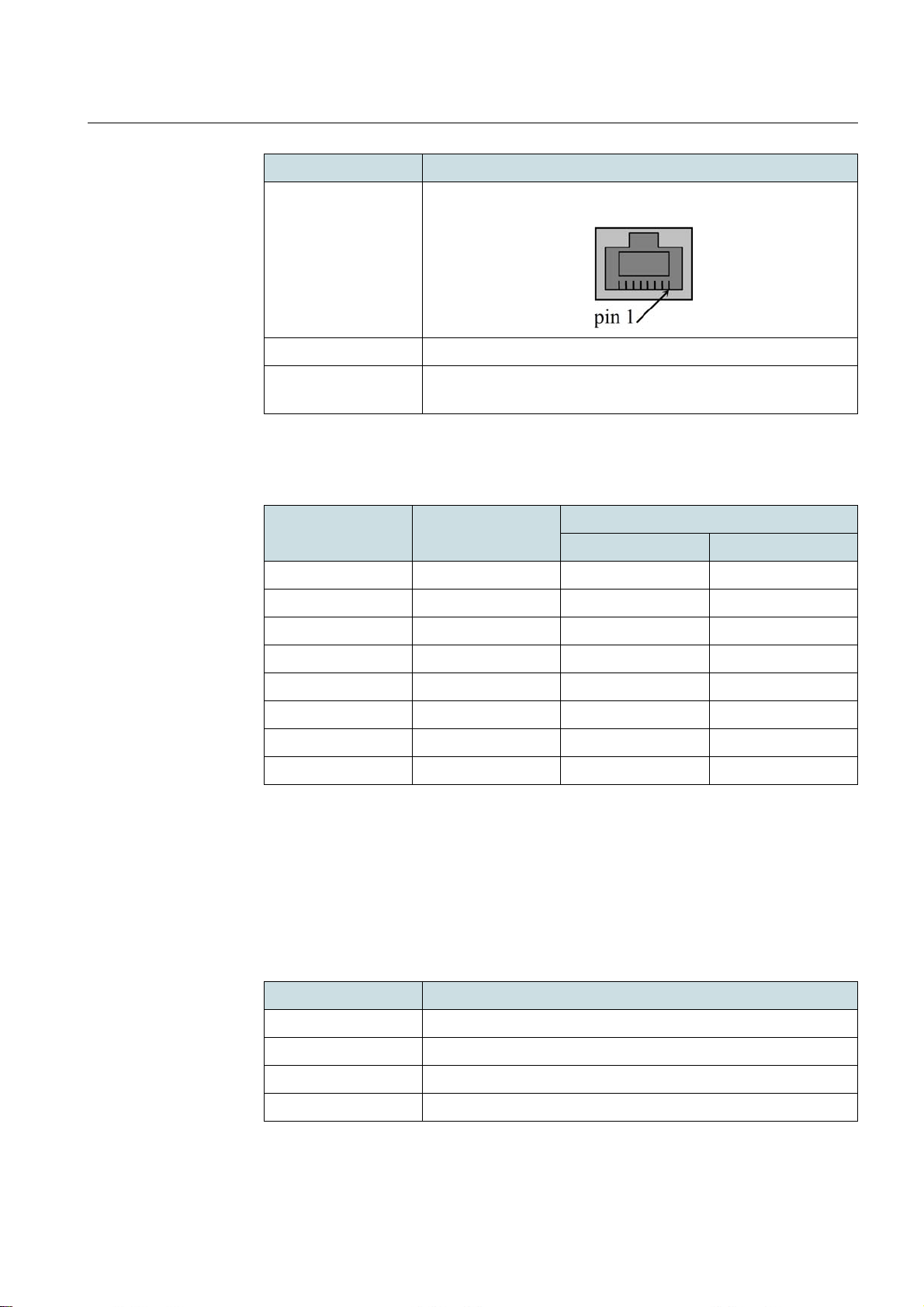
DragonWave Inc. Mechanical Structure and Interfaces
Property Description
Connector type
Suggested cable Shielded twisted pair (STP cat5e), at least 24 AWG wire
Power supply Works as P+E PD port. Lite can be fed by standard PoE+ PSE
Table 9 PoE+ In
The pinout definition is shown in the following table.
Pin Number Pin Function Power Pinout Alternatives
1 pair A+ positive/negative 2 pair A- positive/negative 3 pair B+ negative/positive -
Shielded GE RJ45 8 pin gold plated contacts.
via this port.
Alternative A Alternative B
4 pair C+ - positive
5 pair C- - positive
6 pair B- negative/positive 7 pair D+ - negative
8 pair D- - negative
Table 10 Pinout Definition of PoE+ In
4.2.4 Internal Interface (optional)
This optional Internal interface is located with the PoE+ In interface on the PoE+ module,
which is only required in the PoE+ application. This interface is used to transfer power
and Ethernet traffic between PoE+ and P+E, when Lite is connected with PoE+ PSE via
PoE+ In interface.
Property Description
Interface type 100/1000 Base-T
Duplex mode half and full with auto-negotiation or manual
Rate 100/1000 Mbit/s with auto-negotiation
Front panel reference INTERNAL
Table 11 Internal
37
Page 38
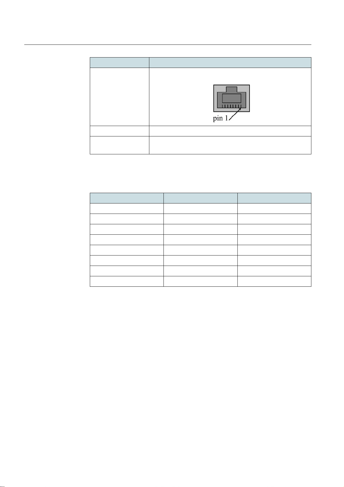
Property Description
DragonWave Inc.Mechanical Structure and Interfaces
Connector type
Suggested cable Shielded twisted pair (STP cat5e), at least 24 AWG wire
Power supply The P+E power pinout is built into this port. It is an internal port
Table 11 Internal
The pinout definition is shown in the following table.
Pin Number Pin Function Power Pinout
1 pair A+ negative
2 pair A- negative
3 pair B+ negative
4pair C+positive
Shielded GE RJ45 8 pin gold plated contacts.
to provide power transfer between P+E and PoE+.
5pair C-positive
6 pair B- negative
7pair D+positive
8pair D-positive
Table 12 Pinout Definition of Internal
4.2.5 RF Interface (optional)
The RF interfaces consist of two N-type antenna connectors located on a box cover.
These interfaces are used when Lite is assembled with external antenna.
4.2.6 RSSI/EVM Interface
RSSI interface enables the measurement of the received RF signal level by means of a
standard voltmeter through a female BNC 50 ohm, an IP66 waterproof connector.
38
Page 39

DragonWave Inc. Mechanical Structure and Interfaces
Parameter Value
Output voltage
range and
received power
range
Accuracy ±1 dB for EVM indication;
Table 13 RSSI/EVM parameters
BCN output = A.BCD;
A.B show EVM, and CD show RSSI;
For example:
BNC = 1.479V means RSSI = -79dBm, EVM = -14dB;
BCN = 2.245V means RSSI = -45dBm, EVM = -22dB.
RSSI indication is mainly used to demonstrate the tren d.
39
Page 40
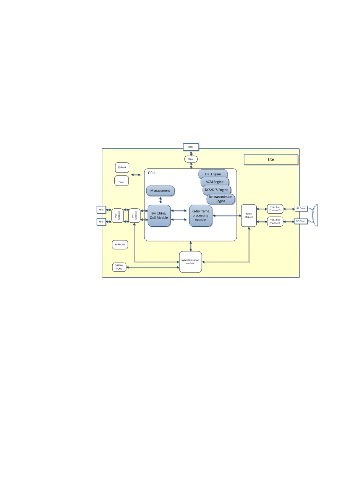
DragonWave Inc.Product Structure
5 Product Structure
Figure 17 shows the top-level block diagram. Lite includes 6 function modules, including
• Frame processing module (switching, QoS, radio frame processing);
• Control function (TPC/ACM/DCS/DFS/Retransmission) processing module;
• Power supply module;
• IEEE 1588v2 processing module;
• Baseband and RF module;
• Antenna.
Figure 17 Function modules of Lite
5.1 Packet Processing Module
The packet processing module provides th e fo llowin g func tio ns :
• Packet switching;
• QoS mapping and scheduling;
• Frame fragmentation and aggregation;
• MAC frame encapsulation.
The packet switching unit switches traffic between an Ethernet port and a radio port, and
also performs VLAN manipulation.
The switch can be done based on port or on MAC learning. Lite supports up to 48 VLANs
switch.
The QoS mapping and scheduling unit maps the QoS class for different traffic an d implements strict priority or WRR/DWRR scheduling to provide different SLA for different
traffic classes.
The frame fragmentation and aggregation unit support aggreg ates different packets into
the same MAC frame to better utilize the radio bandwidth and fragments packets that
40
Page 41

DragonWave Inc. Product Structure
exceed the radio frame limit, to allow long packets to be processed in low modulation
schemes, or low radio bandwidth.
The MAC frame encapsulation unit encapsulates packets into the radio frame.
5.2 Power Supply Module
The power supply module supports power over Ethernet. It generates tertiary voltage
sources which are stabilized, monitored and distributed to the other sections.
5.3 IEEE 1588v2 Module
The 1588 module processes 1588 packets, controls 1588 time stamping and runs the
proprietary 1588-like synchronization process.
5.4 Baseband and RF Module
The baseband and RF module encapsulates the MAC frames into radio frames, modulates and demodulates, encrypts, processes TPC and DFS functions.
5.5 Antenna
The antenna is connected to the RF module. Lite support both integrated antenna and
external antenna which will provide flexibility for customer for installation and other purposes.
41
Page 42

6 Management
Lite can be managed locally or remotely. Both in-band and out-band management are
realized through 3 types of management IP addresse s. Lite can be mana ged by a Webbased GUI (i.e., Link Viewer) or NetViewer. It can also be managed by other standard
third party management systems which support SNMP.
6.1 Web-based GUI (Link Viewer) Management
Through an embedded Link Viewer program in Lite, the user can access Lite system
through network to monitor, administer and configure it. More specifically, with this userfriendly program, the user can perform the following tasks:
• System general parameter management;
• Radio parameter management;
• Service management;
• DCN management;
• Software management;
• Licensing management;
• Performance management;
• Maintenance.
DragonWave Inc.Management
6.2 Accessing
Lite supports the following 3 kinds of management IP addresses to guarantee the operators accessibility in any conditions.
• Public IP to support the management through management VLAN.
The IP address, management VLAN and priority of the management IP are configurable.
• Local management IP to support local access to Lite, collocated Lite and remote
Lite.
It supports direct connection between Lite and the mana gement computer. The local
management IP is configurable.
• Private IP to support Lite access when both public IP and local managem ent IP are
lost.
This IP address only supports the access to local Lite and limited access to radio link
through the private in-band management channel.
6.3 SNMP Agent
Lite has an inbuilt simple network management protocol (SNMP) agent that provides
management functions for the whole radio terminal. Fault, performance and configuration management functions can be performed using SNMP actions. The version supported is SNMP v2c.
42
6.4 SNTP, SFTP and SSH
The simple network time protocol (SNTP) functionality is used to update the real time
clock of the node by connecting to an NTP server, which must be accessible through the
IP-based DCN. The SNTP can be enabled or disabled in NetViewer.
Page 43

DragonWave Inc. Management
Secured file transfer protocol (SFTP) is supported for the purpose of so ftware download
and large file size downloads, e.g., performance monitoring data.
SSH is supported for remote command interface control.
6.5 Software Upgrade
Lite software can be upgraded from previous release so that new features will be supported without hardware change. The upgrade can be performed both locally or
remotely by Link Viewer.
6.6 License
The user who wants to use certain features ha s to purchase the corresponding licenses.
A license can be purchased together with the hardware and the applica tion software
when the system is initially purchased, or it can be later purchased and installed onto an
already operating system. If the license is ordered together with the equipment, it is
installed during commissioning.
Lite is delivered to the customer with the basic software release and the basic license
pre-installed, so essential functions are enabled. There are additional features that may
be required, for instance, when the network scales up, or network security is required. If
additional features need to be activated, the customer can acquire an upgrading license.
The basic license configuration is 50 Mbps UL + DL capacity.
Lite provides the following upgrading licenses:
• Basic (50 Mbps) to 100 Mbps upgrade license;
• Basic (50 Mbps) to full-capacity (230 Mbps) upgrade license;
• 100 Mbps to full-capacity (230 Mbps) upgrade license;
• License for co-site synchronization;
• License for Ethernet OAM (in future release);
• License for 1588v2 TC clock synchronization (in future release);
• License for security (SNMPv3, SSH and SFTP) (in future release);
• License for Radio Ring (in future release).
The following country code licenses are used to meet different regulations in different
countries. One of them has to be purchased for use in different countries and areas.
• FCC (required in USA);
• ETSI (required in European countries);
• TELEC (required in Japan);
• ANATEL (required in Brazil);
• ICASA (required in South Africa);
• IC (required in Canada);
• RALI (required in Australia);
• ROW (required in rest of the world).
One country code license can only be activated once and is not allowed to be changed
to another one.
In-field license upgrade is also supported, which can be performed by custome r service
staff or by the user. The upgrade can be pe rformed both locally and re motely using DWI
43
Page 44

DragonWave Inc.Management
proprietary EMSs, e.g., Link Viewer. The upgrade may also be performed by other no nDWI proprietary EMSs by the customer themselves.
When the unit is not managed remotely, make sure that the license has been retrieved
for the equipment before going to the site. There are no emergency license available.
44
Page 45
DragonWave Inc. Technical Specification
7 Technical Specification
7.1 Regulation Compliance
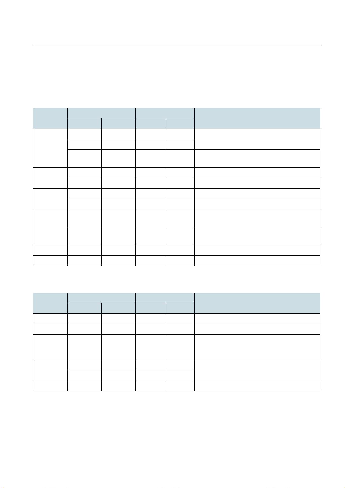
The following tables provide the regulation compliance information.
Regulation Frequency Band (MHz) Channel Bandwidth Regulatory Compliance
Start End 20 MHz 40 MHz
FCC/IC 5250 5350 Yes Yes FCC 47CFR, Part 15, Subpart E and IC RSS-
5470 5725 Yes Yes
5725 5850 Yes Yes FCC 47CFR, Part 15, Subpart C and IC RSS-
ETSI 5470 5725 Yes Yes ETSI EN 301 893
5725 5875 Yes NA ETSI EN 302 502
TELEC 5180 5240 Yes Yes TELEC Item 19-3 of Article 2 Paragraph 1
210
210
5500 5700 Yes Yes TELEC Item 19-3-2 of Article 2 Paragraph 1
ANATEL 5470 5725 Yes Yes ANATEL RESOLUTION No.506, From July 1,
2008 Section X
5725 5850 Yes Yes ANATEL RESOLUTION No.506, From July 1,
2008 Section IX
ICASA 5725 5875 Yes NA South Africa ICASA Vol.547 31 March 2011
ROW 5250 5875 Yes Yes No regulation limitation
Table 14 5 GHz
Regulation Frequency Band (MHz) Channel Bandwidth Regulatory Compliance
Start End 20 MHz 40 MHz
IC 3475 3650 Yes Yes IC RSS-192
FCC/IC 3650 3700 Yes N A FCC Part 90, Subpar t Z an d IC RSS- 19 7
ETSI 3400 3800 Yes Yes ECC RECOMMENDATION (04)05
CEPT/ERC/RECOMMENDATION 12-08 E
Article 21.5 ITU-T Radio Regulations
RALI 3425 3492.5 Yes Yes RALI: FX 19
3542.5 3575 Yes Yes
ROW 3400 3800 Yes Yes No regulation limitation
Table 15 3 GHz
RALI: FX 14
45
Page 46
DragonWave Inc.Technical Specification
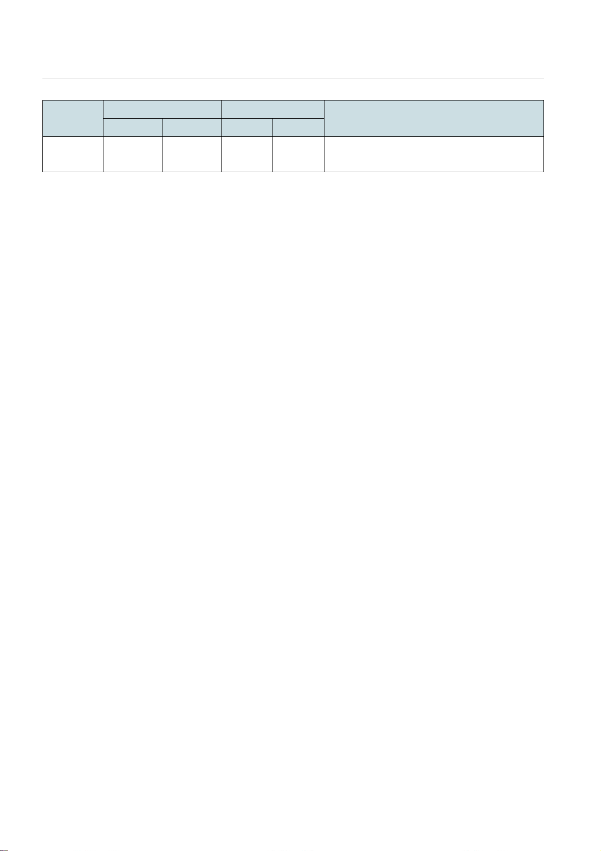
Regulation Frequency Band (MHz) Channel Bandwidth Regulatory Compliance
Start End 20 MHz 40 MHz
ETSI 2570 2620 Yes Yes EC Decision 2008/477/EC
ECC Report 131
Table 16 2 GHz
46
Page 47
DragonWave Inc. Technical Specification
7.2 Radio Performance
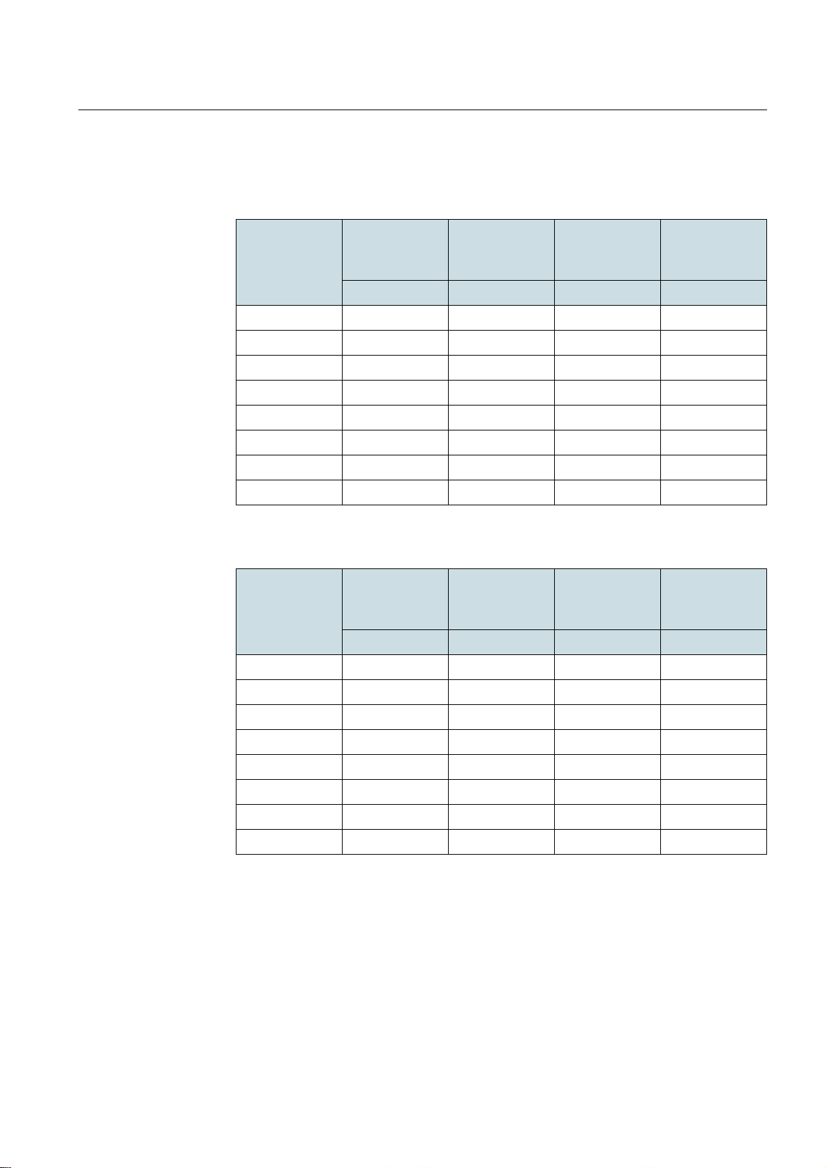
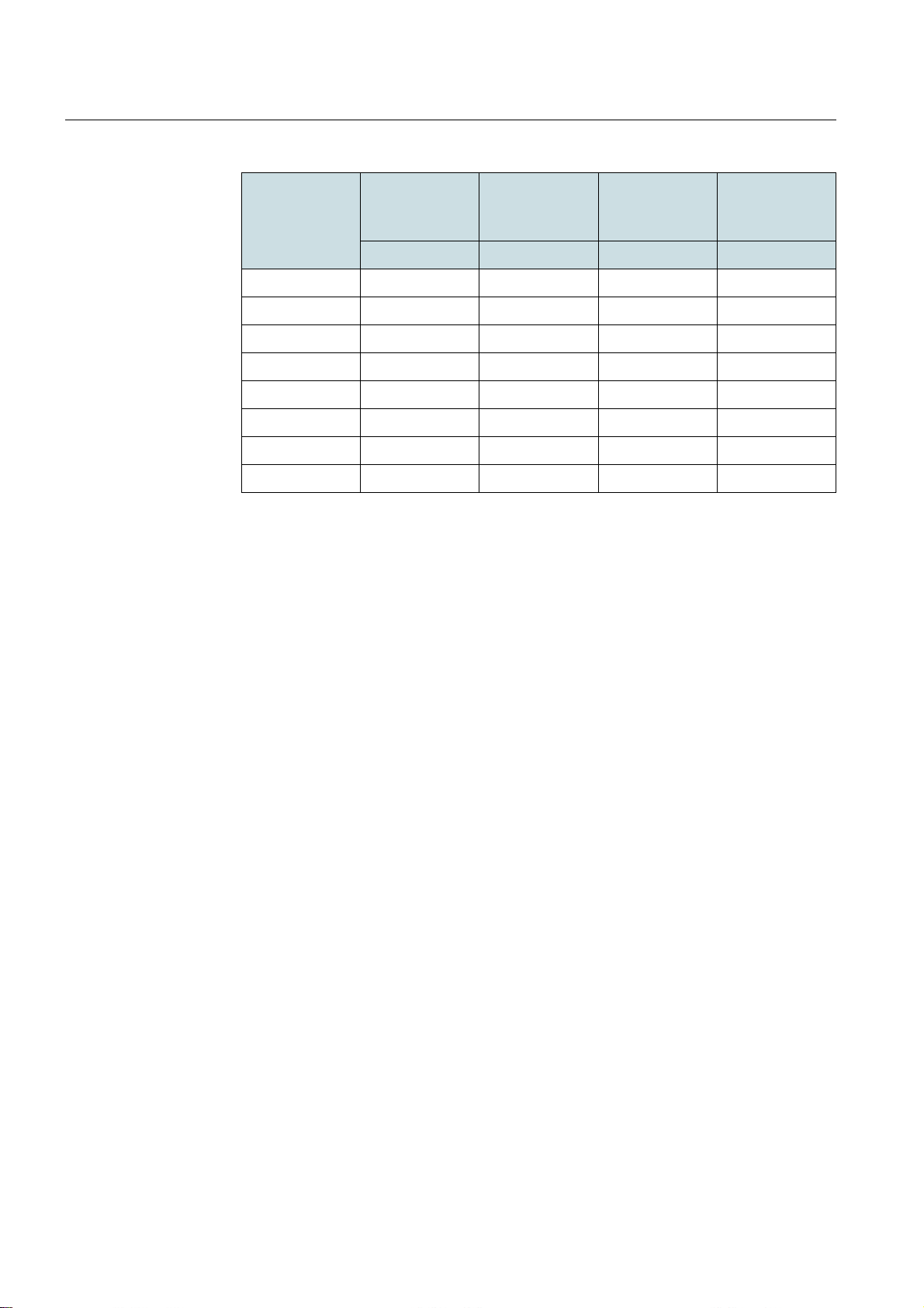
The following tables provide the transmit power and receive sensitivity of the h ardware,
the real transmit power is limited by local regulation.
Modulation
Format
BPSK 1/2 17 17 -83 -81
QPSK 1/2 17 17 -82 -78
QPSK 3/4 17 17 -77 -77
16QAM 1/2 17 17 -76 -74
16QAM 3/4 17 17 -75 -73
64QAM 2/3 17 17 -69 -66
64QAM 3/4 17 17 -69 -66
64QAM 5/6 17 17 -66 -65
Table 17 5 GHz Radio Performance
Modulation
Format
Max Transmit
Power (dBm)
20 MHz 40 MHz 20 MHz 40 MHz
Max Transmit
Power (dBm)
Max Transmit
Power (dBm)
Max Transmit
Power (dBm)
Receiving
Sensitivity
(dBm)
Receiving
Sensitivity
(dBm)
Receiving
Sensitivity
(dBm)
Receiving
Sensitivity
(dBm)
20 MHz 40 MHz 20 MHz 40 MHz
BPSK 1/2 22 22 -83 -82
QPSK 1/2 22 22 -82 -81
QPSK 3/4 22 22 -77 -80
16QAM 1/2 22 22 -76 -75
16QAM 3/4 22 21 -75 -73
64QAM 2/3 21 20 -69 -68
64QAM 3/4 20 19 -69 -66
64QAM 5/6 19 18 -66 -65
Table 18 3 GHz Radio Performance
47
Page 48
DragonWave Inc.Technical Specification
Modulation
Format
BPSK 1/2 26 26 -83 -81
QPSK 1/2 26 26 -82 -78
QPSK 3/4 26 26 -77 -77
16QAM 1/2 26 26 -76 -74
16QAM 3/4 25 25 -75 -73
64QAM 2/3 23 23 -69 -66
64QAM 3/4 22 22 -69 -66
64QAM 5/6 21 21 -66 -65
Table 19 2 GHz Radio Performance
Max Transmit
Power (dBm)
20 MHz 40 MHz 20 MHz 40 MHz
Max Transmit
Power (dBm)
Receiving
Sensitivity
(dBm)
Receiving
Sensitivity
(dBm)
48
Page 49
DragonWave Inc. Technical Specification
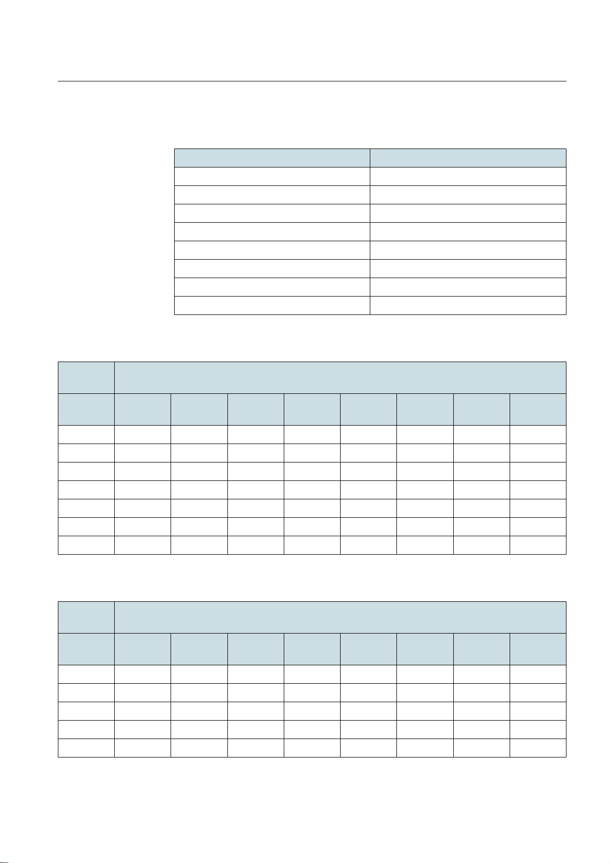
7.3 Ethernet Throughput
The following table shows the Ethernet Throughput of Lite.
MCS Modulation & Coding Rate
8 BPSK 1/2
9 QPSK 1/2
10 QPSK 3/4
11 16 QAM 1/2
12 16 QAM 3/4
13 64 QAM 2/3
14 64 QAM 3/4
15 64 QAM 5/6
Table 20 MCS table
40 MHz/
GI:400 ns
Frame
Size
64 12.60 21.00 42.75 61.81 92.80 116.73 116.66 116.53
128 9.90 18.00 36.00 53.75 78.40 114.43 128.14 143.37
256 9.90 16.50 33.00 48.91 72.00 105.80 117.94 131.36
512 9.00 15.75 31.50 46.23 68.80 101.20 112.84 125.01
1024 9.00 15.00 30.75 44.61 66.40 97.18 108.38 120.77
1280 9.00 15.00 30.75 44.61 67.20 97.75 108.38 121.48
1518 6.19 15.00 30.75 44.61 67.20 92.58 107.10 121.48
Table 21 Ethernet L1 Throughput of 50/50 Tx/Rx Ratio (40 MHz/GI:400 ns)
40 MHz/
GI:800 ns
Frame
Size
BPSK 1/2 QPSK 1/2 QPSK 3/4 16QAM
BPSK 1/2 QPSK 1/2 QPSK 3/4 16QAM
Throughput (Mbps)
16QAM
1/2
Throughput (Mbps)
1/2
3/4
16QAM
3/4
64QAM
2/3
64QAM
2/3
64QAM
3/4
64QAM
3/4
64QAM
64QAM
5/6
5/6
64 9.80 21.00 41.33 57.00 87.75 114.29 116.15 116.03
128 8.40 18.00 34.80 48.00 73.50 102.50 114.43 128.14
256 7.00 16.50 31.90 45.00 67.50 93.79 105.80 117.94
512 7.00 15.75 30.45 43.00 65.25 89.69 101.20 112.84
1024 7.00 15.00 29.73 41.00 62.25 87.12 97.18 108.38
Table 22
Ethernet L1 throughput of 50/50 Tx/Rx ratio (40 MHz/ GI:800 ns)
49
Page 50
DragonWave Inc.Technical Specification
40 MHz/
Throughput (Mbps)
GI:800 ns
Frame
Size
BPSK 1/2 QPSK 1/2 QPSK 3/4 16QAM
1/2
16QAM
3/4
64QAM
2/3
64QAM
3/4
64QAM
1280 7.00 15.00 29.73 41.00 63.00 87.13 97.75 109.01
1518 7.00 15.00 29.73 41.00 63.00 87.13 98.33 109.01
Table 22
20 MHz/
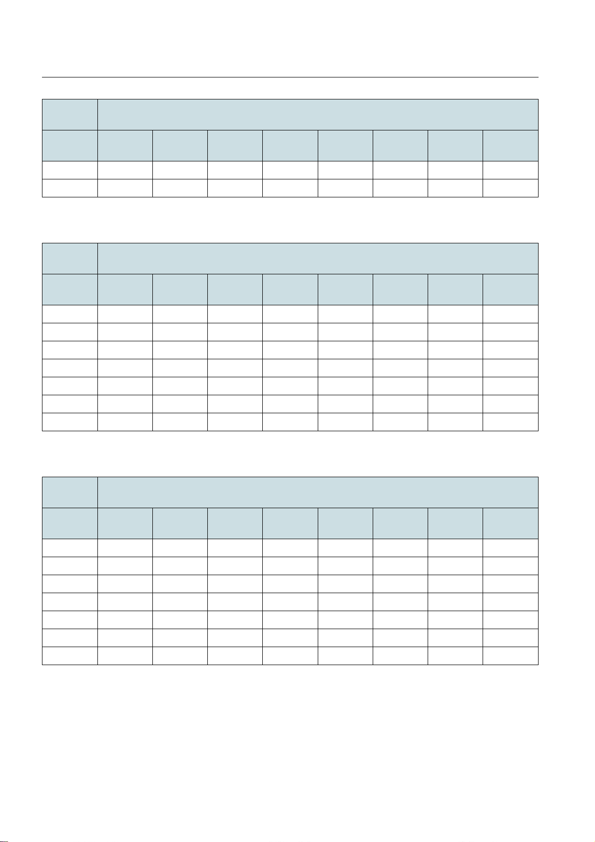
Ethernet L1 throughput of 50/50 Tx/Rx ratio (40 MHz/ GI:800 ns)
Throughput (Mbps)
GI:400 ns
Frame
Size
BPSK 1/2 QPSK 1/2 QPSK 3/4 16QAM
1/2
16QAM
3/4
64QAM
2/3
64QAM
3/4
64QAM
64 2.80 9.80 14.00 18.20 42.75 55.58 58.94 69.60
128 2.00 8.40 12.00 15.60 36.00 46.80 50.23 59.40
256 2.00 7.00 11.00 14.30 33.00 43.88 46.64 54.00
512 2.00 7.00 10.00 13.65 31.50 41.93 44.08 51.60
1024 2.00 7.00 9.38 13.00 30.75 39.98 42.54 49.80
5/6
5/6
1280 2.00 7.00 10.00 13.00 30.75 39.98 42.54 49.80
1518 2.00 7.00 10.00 13.00 30.75 39.98 42.54 49.80
Table 23
20 MHz/
Ethernet L1 throughput of 50/50 Tx/Rx ratio (20 MHz/ GI:400 ns)
Throughput (Mbps)
GI:800 ns
Frame
Size
BPSK 1/2 QPSK 1/2 QPSK 3/4 16QAM
1/2
16QAM
3/4
64QAM
2/3
64QAM
3/4
64QAM
64 2.80 4.38 14.00 21.00 36.40 48.45 60.38 66.13
128 2.00 6.13 12.00 18.00 31.20 40.80 50.93 56.93
256 2.00 7.00 11.00 14.06 28.60 37.40 47.78 52.33
512 2.00 4.38 9.38 15.75 27.30 35.70 45.15 49.45
1024 2.00 7.00 9.38 15.00 26.65 34.85 43.58 47.73
1280 2.00 6.13 10.00 15.00 26.65 34.85 43.58 47.73
1518 2.00 7.00 10.00 15.00 26.65 34.85 43.58 47.73
Table 24
Ethernet L1 throughput of 50/50 Tx/Rx ratio (20 MHz/ GI:800 ns)
5/6
50
Page 51
DragonWave Inc. Technical Specification
40 MHz/
Throughput (Mbps)
GI:400 ns
Frame
Size
BPSK 1/2 QPSK 1/2 QPSK 3/4 16QAM
1/2
16QAM
3/4
64QAM
2/3
64QAM
3/4
64QAM
64 9.60 16.00 32.57 47.10 70.70 88.93 88.89 88.79
128 8.56 15.57 31.14 46.49 67.81 98.96 110.82 123.99
256 9.18 15.30 30.61 45.37 66.78 98.13 109.39 121.84
512 8.66 15.16 30.32 44.49 66.21 97.40 108.60 120.31
1024 8.83 14.71 30.16 43.76 65.13 95.31 106.30 118.46
1280 8.86 14.77 30.28 43.93 66.17 96.25 106.71 119.61
1518 6.11 14.80 30.35 44.03 66.33 91.37 105.71 119.90
Table 25
40 MHz/
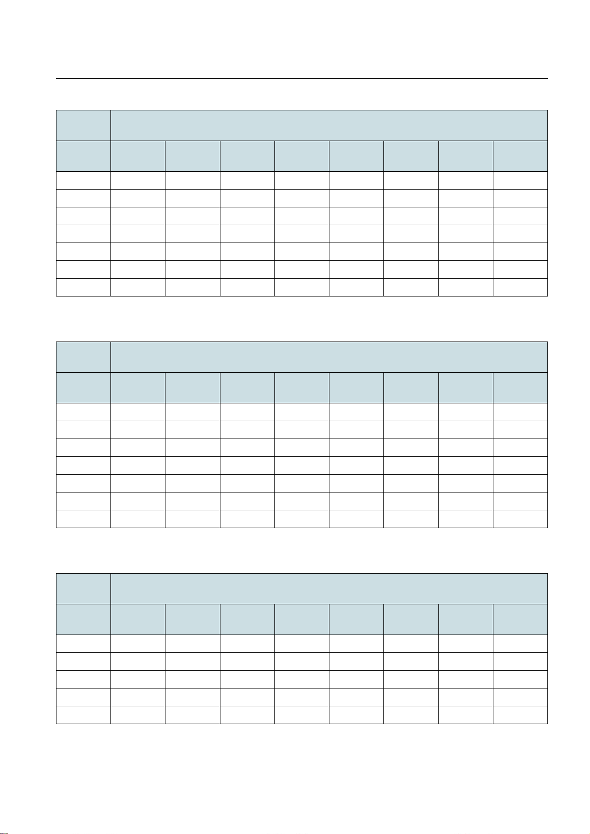
Ethernet L2 throughput of 50/50 Tx/Rx ratio (40 MHz/ GI:400 ns)
Throughput (Mbps)
GI:800 ns
Frame
Size
BPSK 1/2 QPSK 1/2 QPSK 3/4 16QAM
1/2
16QAM
3/4
64QAM
2/3
64QAM
3/4
64QAM
5/6
5/6
64 7.47 16.00 31.49 43.43 66.86 87.08 88.50 88.40
128 7.26 15.57 30.10 41.51 63.57 88.65 98.96 110.82
256 6.49 15.30 29.59 41.74 62.61 86.99 98.13 109.39
512 6.74 15.16 29.31 41.38 62.80 86.32 97.40 108.60
1024 6.87 14.71 29.16 40.21 61.06 85.46 95.31 106.30
1280 6.89 14.77 29.27 40.37 62.03 85.78 96.25 107.34
1518 6.91 14.80 29.34 40.47 62.18 85.99 97.05 107.60
Table 26
20 MHz/
Ethernet L2 throughput of 50/50 Tx/Rx ratio (40 MHz/ GI:800 ns)
Throughput (Mbps)
GI:400 ns
Frame
Size
BPSK 1/2 QPSK 1/2 QPSK 3/4 16QAM
1/2
16QAM
3/4
64QAM
2/3
64QAM
3/4
64QAM
64 2.13 7.47 10.67 13.87 32.57 42.34 44.90 53.03
128 1.73 7.26 10.38 13.49 31.14 40.48 43.44 51.37
256 1.86 6.49 10.20 13.26 30.61 40.70 43.26 50.09
512 1.92 6.74 9.62 13.14 30.32 40.35 42.42 49.66
5/6
1024 1.96 6.87 9.20 12.75 30.16 39.21 41.72 48.85
Table 27
Ethernet L2 throughput of 50/50 Tx/Rx ratio (20 MHz/ GI:400 ns)
51
Page 52
DragonWave Inc.Technical Specification
20 MHz/
Throughput (Mbps)
GI:400 ns
Frame
Size
BPSK 1/2 QPSK 1/2 QPSK 3/4 16QAM
1/2
16QAM
3/4
64QAM
2/3
64QAM
3/4
64QAM
1280 1.97 6.89 9.85 12.80 30.28 39.36 41.88 49.03
1518 1.97 6.91 9.87 12.83 30.35 39.46 41.98 49.15
Table 27
20 MHz/
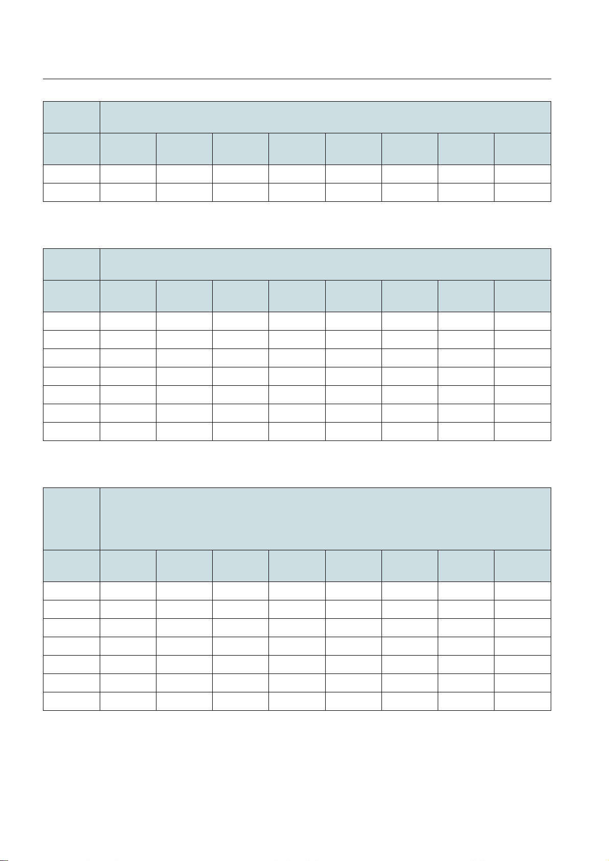
Ethernet L2 throughput of 50/50 Tx/Rx ratio (20 MHz/ GI:400 ns)
Throughput (Mbps)
GI:800 ns
Frame
Size
BPSK 1/2 QPSK 1/2 QPSK 3/4 16QAM
1/2
16QAM
3/4
64QAM
2/3
64QAM
3/4
64QAM
64 2.13 3.33 10.67 16.00 27.73 36.91 46.00 50.38
128 1.73 5.30 10.38 15.57 26.98 35.29 44.04 49.23
256 1.86 6.49 10.20 13.04 26.53 34.69 44.31 48.53
512 1.92 4.21 9.02 15.16 26.27 34.36 43.45 47.59
1024 1.96 6.87 9.20 14.71 26.14 34.18 42.74 46.81
5/6
5/6
1280 1.97 6.03 9.85 14.77 26.24 34.31 42.90 46.99
1518 1.97 6.91 9.87 14.80 26.30 34.40 43.01 47.10
Table 28
40 MHz/
Ethernet L2 throughput of 50/50 Tx/Rx ratio (20 MHz/ GI:800 ns)
Throughput (Mbps)
GI:400 ns/
Tx Ratio:
70
Frame
Size
BPSK 1/2 QPSK 1/2 QPSK 3/4 16QAM
1/2
16QAM
3/4
64QAM
2/3
64QAM
3/4
64QAM
64 14.74 60.29 85.97 94.81 127.28 177.60 188.35 189.72
128 12.65 60.04 85.08 93.16 125.98 170.72 181.61 199.68
256 11.79 59.02 85.62 90.20 123.93 167.42 177.94 193.37
512 11.76 57.74 84.38 89.87 123.16 165.65 173.28 189.41
1024 11.45 59.04 83.16 90.05 123.16 165.65 173.28 188.65
1280 11.41 59.29 83.51 90.62 123.93 166.07 176.01 190.58
1518 11.38 59.29 83.69 91.32 123.67 167.42 175.83 193.63
5/6
Table 29
52
Ethernet L1 Tx throughput of 70/30 Tx/Rx ratio (40 MHz/ GI:400 ns)
Page 53
DragonWave Inc. Technical Specification
40 MHz/
Throughput (Mbps)
GI:400 ns/
Tx Ratio:
30
Frame
Size
BPSK 1/2 QPSK 1/2 QPSK 3/4 16QAM
1/2
16QAM
3/4
64QAM
2/3
64QAM
3/4
64QAM
64 5.72 49.56 59.99 55.32 70.40 89.30 88.95 95.85
128 5.33 46.07 59.85 54.07 70.28 88.36 87.21 93.36
256 5.14 45.65 58.60 54.30 69.10 85.99 85.09 91.82
512 4.96 47.26 56.95 54.43 69.10 85.99 84.39 90.47
1024 4.86 46.84 58.55 53.82 69.10 85.99 85.09 91.05
1280 4.84 46.84 58.55 53.82 69.10 84.55 85.47 91.82
1518 4.83 46.84 58.55 53.82 69.10 84.55 86.19 91.63
Table 30
40 MHz/
Ethernet L1 Rx throughput of 70/30 Tx/Rx ratio (40 MHz/ GI:400 ns)
Throughput (Mbps)
GI:800 ns/
Tx Ratio:
70
5/6
Frame
Size
BPSK 1/2 QPSK 1/2 QPSK 3/4 16QAM
1/2
16QAM
3/4
64QAM
2/3
64QAM
3/4
64QAM
64 12.78 66.20 83.09 88.44 125.49 158.60 169.90 188.35
128 11.07 65.60 82.09 87.65 120.21 152.70 163.90 181.61
256 10.32 64.49 81.23 85.34 119.28 149.54 160.58 177.94
512 10.30 62.99 81.41 85.28 117.33 147.56 159.02 173.28
1024 10.01 64.47 80.73 85.28 116.36 147.79 158.36 173.37
1280 9.97 64.74 80.57 85.28 117.33 148.78 160.11 175.92
1518 9.95 64.74 80.90 85.17 118.31 149.76 160.58 176.53
Table 31
Ethernet L1 Tx throughput of 70/30 Tx/Rx ratio (40 MHz/ GI:800 ns)
5/6
53
Page 54
DragonWave Inc.Technical Specification
40 MHz/
Throughput (Mbps)
GI:800 ns/
Tx Ratio:
30
Frame
Size
BPSK 1/2 QPSK 1/2 QPSK 3/4 16QAM
1/2
16QAM
3/4
64QAM
2/3
64QAM
3/4
64QAM
64 4.91 56.30 57.97 52.39 68.12 80.07 82.40 88.95
128 4.82 50.02 57.86 51.20 68.05 79.22 81.46 87.21
256 4.50 50.95 56.63 51.44 66.91 78.38 79.19 85.09
512 3.96 56.87 55.29 51.44 66.91 78.38 79.19 84.39
1024 4.25 52.28 56.59 47.44 69.17 77.08 79.57 85.09
1280 4.24 52.28 56.59 49.22 67.99 78.38 77.86 85.47
1518 4.22 52.28 56.59 47.44 69.17 77.08 78.24 86.19
Table 32
20 MHz/
Ethernet L1 Rx throughput of 70/30 Tx/Rx ratio (40 MHz/ GI:800 ns)
Throughput (Mbps)
GI:400 ns/
Tx Ratio:
70
5/6
Frame
Size
BPSK 1/2 QPSK 1/2 QPSK 3/4 16QAM
1/2
16QAM
3/4
64QAM
2/3
64QAM
3/4
64QAM
64 3.40 84.95 43.39 43.55 93.97 85.37 82.99 97.50
128 3.21 78.42 42.98 44.10 90.92 84.88 82.02 94.81
256 3.00 78.42 42.42 44.44 90.92 82.14 80.03 93.28
512 2.80 83.59 42.89 43.55 89.40 82.58 80.03 92.51
1024 2.74 82.83 42.97 43.66 89.40 81.20 80.39 92.51
1280 2.73 82.83 38.96 46.29 90.92 82.14 80.03 93.28
1518 2.82 80.47 42.97 43.66 90.92 82.14 80.03 94.06
Table 33
Ethernet L1 Tx throughput of 70/30 Tx/Rx ratio (20 MHz/ GI:400 ns)
5/6
54
Page 55
DragonWave Inc. Technical Specification
20 MHz/
Throughput (Mbps)
GI:400 ns/
Tx Ratio:
30
Frame
Size
BPSK 1/2 QPSK 1/2 QPSK 3/4 16QAM
1/2
16QAM
3/4
64QAM
2/3
64QAM
3/4
64QAM
64 1.46 71.13 36.18 32.55 67.45 50.96 46.31 53.03
128 1.28 79.31 32.75 32.78 67.45 49.24 45.48 52.03
256 1.20 79.31 35.18 33.29 64.06 49.24 45.48 52.03
512 1.15 79.31 34.83 33.54 61.84 50.18 45.48 52.03
1024 1.13 79.31 22.32 48.01 64.06 47.55 46.23 52.03
1280 1.13 79.31 34.83 33.54 64.06 49.24 45.48 52.03
1518 1.12 79.31 34.83 33.54 64.06 49.24 45.48 52.03
Table 34
20 MHz/
Ethernet L1 Rx throughput of 70/30 Tx/Rx ratio (20 MHz/ GI:400 ns)
Throughput (Mbps)
GI:800 ns/
Tx Ratio:
70
5/6
Frame
Size
BPSK 1/2 QPSK 1/2 QPSK 3/4 16QAM
1/2
16QAM
3/4
64QAM
2/3
64QAM
3/4
64QAM
64 3.40 84.95 43.39 51.98 73.30 77.17 89.29 92.72
128 3.21 78.42 42.98 50.88 73.28 76.36 87.59 90.33
256 3.00 78.42 42.42 51.27 72.07 75.54 85.15 88.12
512 2.80 83.59 42.89 50.24 72.07 75.54 85.15 87.38
1024 2.74 82.83 42.97 50.37 72.07 74.27 85.57 88.12
1280 2.82 80.47 42.97 50.37 72.07 75.54 85.15 88.85
1518 2.82 80.47 42.97 50.37 72.07 75.54 85.87 88.66
Table 35
Ethernet L1 Tx throughput of 70/30 Tx/Rx ratio (20 MHz/ GI:800 ns)
5/6
55
Page 56
DragonWave Inc.Technical Specification
20 MHz/
Throughput (Mbps)
GI:800 ns/
Tx Ratio:
30
Frame
Size
BPSK 1/2 QPSK 1/2 QPSK 3/4 16QAM
1/2
16QAM
3/4
64QAM
2/3
64QAM
3/4
64QAM
64 1.46 71.13 36.18 37.56 52.71 48.03 50.62 50.29
128 1.28 79.31 32.75 37.82 52.71 46.42 49.75 49.34
256 1.20 79.31 35.18 35.78 50.91 47.35 49.75 49.34
512 1.15 72.46 37.56 38.69 50.18 46.42 49.75 49.34
1024 1.13 77.97 35.33 38.69 50.18 46.42 49.75 49.34
1280 1.13 79.31 34.83 38.69 50.18 46.42 49.75 49.34
1518 1.12 77.97 35.33 38.69 50.18 46.42 49.75 49.34
Table 36
40 MHz/
Ethernet L1 Rx throughput of 70/30 Tx/Rx ratio (20 MHz/ GI:800 ns)
Throughput (Mbps)
GI:400 ns/
Tx Ratio:
70
5/6
Frame
Size
BPSK 1/2 QPSK 1/2 QPSK 3/4 16QAM
1/2
16QAM
3/4
64QAM
2/3
64QAM
3/4
64QAM
64 11.23 21.68 44.72 65.51 97.51 147.37 165.84 169.30
128 10.94 21.23 43.81 63.96 95.97 141.28 159.09 177.38
256 10.94 20.87 43.72 61.89 93.66 137.96 155.41 171.32
512 11.32 20.87 43.09 61.38 92.89 136.30 151.11 167.27
1024 11.23 21.23 42.82 61.38 92.89 136.30 151.11 166.60
1280 11.23 21.32 43.09 61.89 93.66 136.85 153.57 168.62
1518 11.23 21.32 43.18 62.41 93.66 137.96 153.57 171.32
Table 37
Ethernet L2 Tx throughput of 70/30 Tx/Rx ratio (40 MHz/ GI:400 ns)
5/6
56
Page 57
DragonWave Inc. Technical Specification
40 MHz/
Throughput (Mbps)
GI:400 ns/
Tx Ratio:
30
Frame
Size
BPSK 1/2 QPSK 1/2 QPSK 3/4 16QAM
1/2
16QAM
3/4
64QAM
2/3
64QAM
3/4
64QAM
64 4.36 8.87 18.43 26.53 40.14 59.60 66.60 73.71
128 4.61 8.63 18.04 25.64 39.48 58.65 65.03 71.40
256 4.77 8.79 17.89 25.64 38.82 56.75 62.92 69.67
512 4.77 9.10 17.81 25.64 38.82 56.75 62.40 68.51
1024 4.77 9.02 18.20 25.64 38.82 56.75 62.92 69.09
1280 4.77 9.02 18.20 25.64 38.82 55.80 62.92 69.67
1518 4.77 9.02 18.20 25.64 38.82 55.80 63.45 69.67
Table 38
40 MHz/
Ethernet L2 Rx throughput of 70/30 Tx/Rx ratio (40 MHz/ GI:400 ns)
Throughput (Mbps)
GI:800 ns/
Tx Ratio:
70
5/6
Frame
Size
BPSK 1/2 QPSK 1/2 QPSK 3/4 16QAM
1/2
16QAM
3/4
64QAM
2/3
64QAM
3/4
64QAM
64 9.74 21.68 43.22 60.46 94.30 130.85 147.37 165.84
128 9.57 21.23 42.27 59.50 89.97 124.93 141.28 159.09
256 9.57 20.87 41.48 57.58 88.53 121.98 137.96 155.41
512 9.91 20.87 41.57 57.58 87.08 120.00 136.30 151.11
1024 9.82 21.23 41.57 57.58 86.36 120.00 135.74 151.11
1280 9.82 21.32 41.57 57.58 87.08 120.99 137.40 153.57
1518 9.82 21.32 41.74 57.58 87.81 121.98 137.96 154.18
Table 39
Ethernet L2 Tx throughput of 70/30 Tx/Rx ratio (40 MHz/ GI:800 ns)
5/6
57
Page 58
DragonWave Inc.Technical Specification
40 MHz/
Throughput (Mbps)
GI:800 ns/
Tx Ratio:
30
Frame
Size
BPSK 1/2 QPSK 1/2 QPSK 3/4 16QAM
1/2
16QAM
3/4
64QAM
2/3
64QAM
3/4
64QAM
64 9.74 21.68 43.22 60.46 94.30 130.85 147.37 165.84
128 9.57 21.23 42.27 59.50 89.97 124.93 141.28 159.09
256 9.57 20.87 41.48 57.58 88.53 121.98 137.96 155.41
512 9.91 20.87 41.57 57.58 87.08 120.00 136.30 151.11
1024 9.82 21.23 41.57 57.58 86.36 120.00 135.74 151.11
1280 9.82 21.32 41.57 57.58 87.08 120.99 137.40 153.57
1518 9.82 21.32 41.74 57.58 87.81 121.98 137.96 154.18
Table 40
20 MHz/
Ethernet L2 Rx throughput of 70/30 Tx/Rx ratio (40 MHz/ GI:800 ns)
Throughput (Mbps)
GI:400 ns/
Tx Ratio:
70
5/6
Frame
Size
BPSK 1/2 QPSK 1/2 QPSK 3/4 16QAM
1/2
16QAM
3/4
64QAM
2/3
64QAM
3/4
64QAM
64 2.59 9.74 14.21 18.09 44.63 58.95 61.97 73.71
128 2.78 9.57 13.91 18.09 43.18 58.01 60.99 71.40
256 2.78 9.57 13.73 18.09 43.18 56.14 59.01 69.67
512 2.69 9.91 14.21 18.09 42.46 56.14 59.01 69.09
1024 2.69 9.82 14.15 18.09 42.46 55.20 59.01 69.09
1280 2.69 9.82 12.83 18.09 43.18 56.14 59.01 69.67
1518 2.78 9.82 14.15 18.09 43.18 56.14 59.01 70.25
Table 41
Ethernet L2 Tx throughput of 70/30 Tx/Rx ratio (20 MHz/ GI:400 ns)
5/6
58
Page 59
DragonWave Inc. Technical Specification
20 MHz/
Throughput (Mbps)
GI:400 ns/
Tx Ratio:
30
Frame
Size
BPSK 1/2 QPSK 1/2 QPSK 3/4 16QAM
1/2
16QAM
3/4
64QAM
2/3
64QAM
3/4
64QAM
64 1.11 3.74 5.70 7.22 17.89 24.06 25.29 29.61
128 1.11 4.17 5.65 7.22 17.89 23.25 24.45 28.62
256 1.11 4.17 6.07 7.75 17.89 23.25 24.45 28.62
512 1.11 4.17 6.01 7.75 17.27 23.25 24.45 28.62
1024 1.11 4.17 3.85 7.75 17.89 22.45 24.45 28.62
1280 1.11 4.17 6.01 7.75 17.89 23.25 24.45 28.62
1518 1.11 4.17 6.01 7.75 17.89 23.25 24.45 28.62
Table 42
20 MHz/
Ethernet L2 Rx throughput of 70/30 Tx/Rx ratio (20 MHz/ GI:400 ns)
Throughput (Mbps)
GI:800 ns/
Tx Ratio:
70
5/6
Frame
Size
BPSK 1/2 QPSK 1/2 QPSK 3/4 16QAM
1/2
16QAM
3/4
64QAM
2/3
64QAM
3/4
64QAM
64 2.59 9.74 14.21 21.59 38.05 50.58 63.99 70.64
128 2.78 9.57 13.91 20.87 37.42 49.76 62.48 68.43
256 2.78 9.57 13.73 20.87 36.80 48.94 60.45 66.21
512 2.69 9.91 14.21 20.87 36.80 48.94 60.45 65.66
1024 2.69 9.82 14.15 20.87 36.80 48.12 60.45 66.21
1280 2.78 9.82 14.15 20.87 36.80 48.94 60.45 66.76
1518 2.78 9.82 14.15 20.87 36.80 48.94 60.96 66.76
Table 43
Ethernet L2 Tx throughput of 70/30 Tx/Rx ratio (20 MHz/ GI:800 ns)
5/6
59
Page 60
DragonWave Inc.Technical Specification
20 MHz/
GI:800 ns/
Tx Ratio:
30
Frame
Size
64 1.11 3.74 5.70 8.33 15.50 20.97 25.91 28.38
128 1.11 4.17 5.65 8.33 15.50 20.27 25.04 27.43
256 1.11 4.17 6.07 8.33 14.97 20.27 25.04 27.43
512 1.11 3.81 6.01 8.94 15.50 20.27 25.04 27.43
1024 1.11 4.10 6.01 8.94 15.50 20.27 25.04 27.43
1280 1.11 4.17 6.01 8.94 15.50 20.27 25.04 27.43
1518 1.11 4.10 6.01 8.94 15.50 20.27 25.04 27.43
Table 44
BPSK 1/2 QPSK 1/2 QPSK 3/4 16QAM
Ethernet L2 Rx throughput of 70/30 Tx/Rx ratio (20 MHz/ GI:800 ns)
Throughput (Mbps)
16QAM
1/2
3/4
64QAM
2/3
64QAM
3/4
64QAM
7.4 Latency
The following tables show the latency of Lite.
5/6
40 MHz/
GI:400 ns
MCS BPSK
Coding
1/2
64 4.02 4.97 1.72 1.59 1.76 1.80 1.79 1.92
128 3.47 3.78 1.55 1.71 1.65 1.67 1.82 1.83
256 3.22 3.65 1.57 1.67 1.74 1.75 1.73 1.84
512 3.42 3.55 1.62 1.67 1.75 1.75 1.69 1.84
1024 3.84 3.74 1.75 1.63 1.65 1.67 1.70 1.84
1280 3.60 3.89 1.86 1.86 1.69 1.69 1.67 1.84
1518 3.69 3.81 1.89 1.84 1.69 1.77 1.71 1.84
Table 45
Latency - 50/50 Tx/Rx Ratio 40 MHz/GI:400 ns
QPSK
Coding
1/2
QPSK
Coding
3/4
Latency (ms)
16 QAM
Coding
1/2
16 QAM
Coding
3/4
64 QAM
Coding
2/3
64 QAM
Coding
3/4
64 QAM
Coding
5/6
60
Page 61
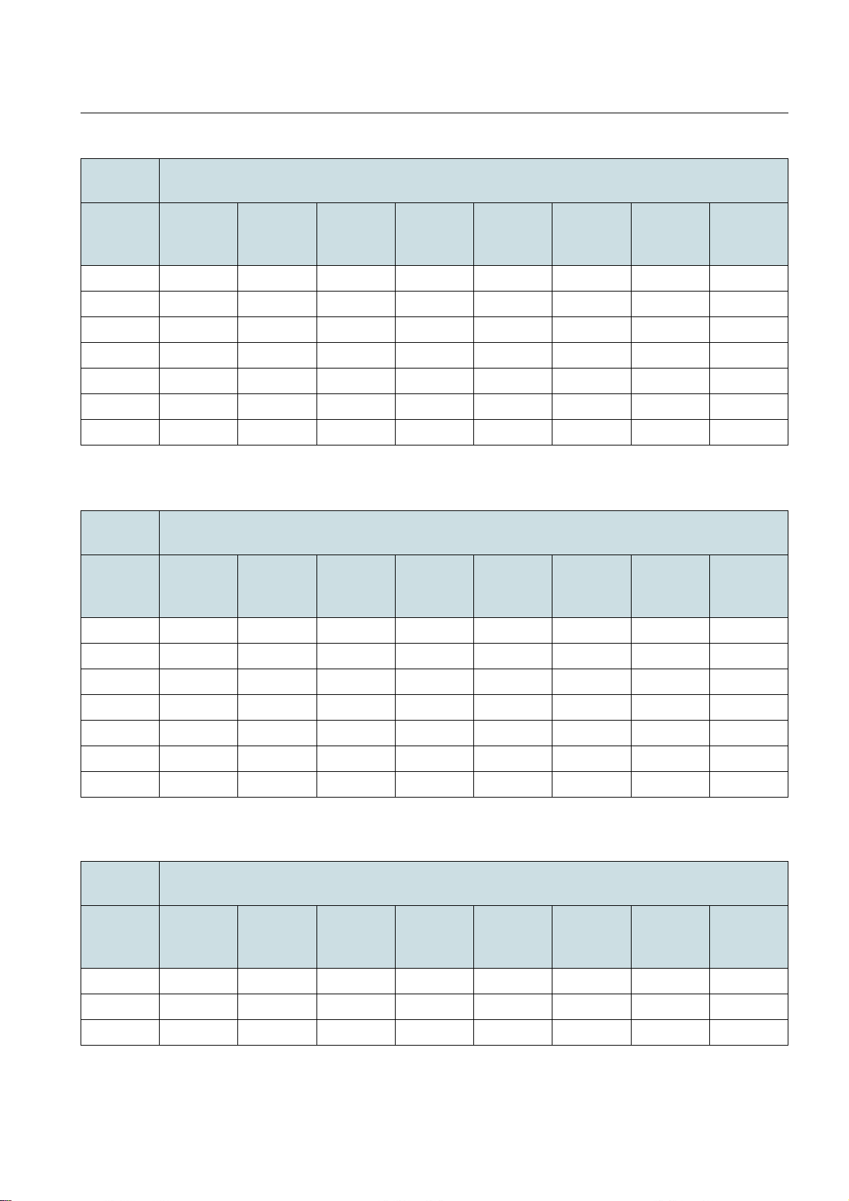
DragonWave Inc. Technical Specification
40 MHz/
Latency (ms)
GI:800 ns
MCS BPSK
Coding
1/2
QPSK
Coding
1/2
QPSK
Coding
3/4
16 QAM
Coding
1/2
16 QAM
Coding
3/4
64 QAM
Coding
2/3
64 QAM
Coding
3/4
64 8.19 9.59 1.76 1.62 1.77 1.85 1.80 1.80
128 3.60 3.60 1.57 1.65 1.66 1.67 1.70 1.86
256 3.63 3.40 1.58 1.58 1.78 1.68 1.79 1.77
512 3.60 3.46 1.67 1.60 1.72 1.69 1.79 1.74
1024 3.53 3.68 1.79 1.56 1.65 1.71 1.71 1.75
1280 3.66 3.79 1.88 1.90 1.74 1.74 1.71 1.72
1518 4.15 3.77 1.95 1.82 1.73 1.79 1.81 1.75
Table 46
20 MHz/
Latency - 50/50 Tx/Rx Ratio 40 MHz/GI:800 ns
Latency (ms)
GI:400 ns
MCS BPSK
Coding
1/2
QPSK
Coding
1/2
QPSK
Coding
3/4
16 QAM
Coding
1/2
16 QAM
Coding
3/4
64 QAM
Coding
2/3
64 QAM
Coding
3/4
64 QAM
Coding
5/6
64 QAM
Coding
5/6
64 4.92 4.28 4.90 5.19 1.75 1.63 1.63 1.69
128 4.51 3.59 3.89 3.95 1.58 1.66 1.65 1.78
256 3.91 3.62 3.56 3.74 1.61 1.63 1.68 1.82
512 3.64 3.58 3.59 3.82 1.66 1.63 1.65 1.76
1024 4.62 3.54 3.88 3.89 1.77 1.65 1.66 1.62
1280 5.51 3.66 3.79 3.99 1.91 1.85 1.88 1.76
1518 5.68 4.34 4.00 4.03 1.91 1.84 1.91 1.91
Table 47 Latency - 50/50 Tx/Rx Ratio 20 MHz/GI:400 ns
20 MHz/
Latency (ms)
GI:800 ns
MCS BPSK
Coding
1/2
QPSK
Coding
1/2
QPSK
Coding
3/4
16 QAM
Coding
1/2
16 QAM
Coding
3/4
64 QAM
Coding
2/3
64 QAM
Coding
3/4
64 4.69 4.13 4.52 4.63 1.75 1.64 1.68 1.66
128 4.55 3.64 3.71 3.65 1.58 1.64 1.70 1.81
256 3.95 3.35 3.37 3.44 1.60 1.61 1.71 1.78
64 QAM
Coding
5/6
Table 48
Latency - 50/50 Tx/Rx Ratio 20 MHz/GI:800 ns
61
Page 62
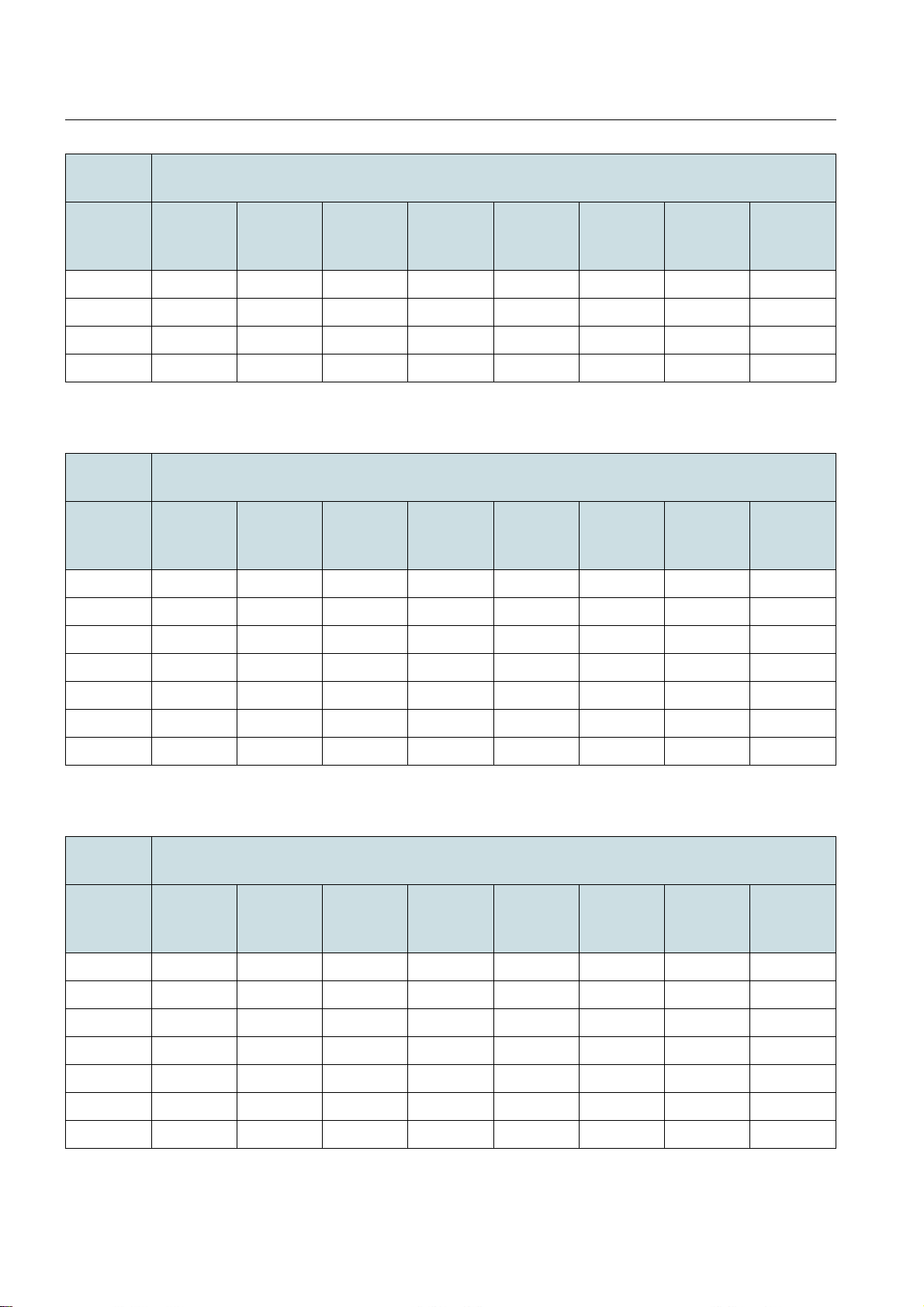
DragonWave Inc.Technical Specification
20 MHz/
Latency (ms)
GI:800 ns
MCS BPSK
Coding
1/2
QPSK
Coding
1/2
QPSK
Coding
3/4
16 QAM
Coding
1/2
16 QAM
Coding
3/4
64 QAM
Coding
2/3
64 QAM
Coding
3/4
512 3.60 3.63 3.64 3.34 1.71 1.68 1.68 1.77
1024 4.69 3.60 3.83 3.58 1.86 1.79 1.70 1.72
1280 5.56 3.89 3.98 3.65 1.91 1.94 1.90 1.90
1518 5.75 4.27 3.92 4.99 1.99 1.79 1.89 1.92
Table 48
40 MHz/
Latency - 50/50 Tx/Rx Ratio 20 MHz/GI:800 ns
Latency (ms)
GI:400 ns
MCS BPSK
Coding
1/2
QPSK
Coding
1/2
QPSK
Coding
3/4
16 QAM
Coding
1/2
16 QAM
Coding
3/4
64 QAM
Coding
2/3
64 QAM
Coding
3/4
64 3.12 1.94 2.02 1.94 2.08 2.10 2.23 2.30
128 3.28 1.99 2.04 2.10 1.98 2.11 2.22 2.18
64 QAM
Coding
5/6
64 QAM
Coding
5/6
256 3.32 1.93 2.06 2.15 2.10 2.22 2.16 2.17
512 3.51 1.94 2.08 2.23 2.15 2.25 2.19 2.21
1024 3.80 2.34 2.08 2.09 2.11 2.21 2.18 2.23
1280 3.68 2.36 2.31 2.19 2.15 2.25 2.18 2.20
1518 3.85 2.31 2.31 2.18 2.21 2.28 2.18 2.21
Table 49
40 MHz/
Latency - 70/30 Tx/Rx Ratio 40 MHz/GI:400 ns
Latency (ms)
GI:800 ns
MCS BPSK
Coding
1/2
QPSK
Coding
1/2
QPSK
Coding
3/4
16 QAM
Coding
1/2
16 QAM
Coding
3/4
64 QAM
Coding
2/3
64 QAM
Coding
3/4
64 3.09 1.96 1.98 2.15 2.08 2.14 2.08 2.23
128 3.29 2.03 2.00 2.17 2.19 2.18 2.10 2.22
256 3.41 1.90 2.06 2.22 2.06 2.17 2.21 2.16
512 3.54 1.90 2.10 2.25 2.15 2.21 2.24 2.19
1024 3.66 2.26 2.10 2.11 2.12 2.17 2.18 2.18
64 QAM
Coding
5/6
1280 3.80 2.35 2.34 2.29 2.15 2.16 2.23 2.18
1518 3.99 2.33 2.29 2.31 2.22 2.23 2.25 2.18
Table 50
Latency - 70/30 Tx/Rx Ratio 40 MHz/GI:800 ns
62
Page 63
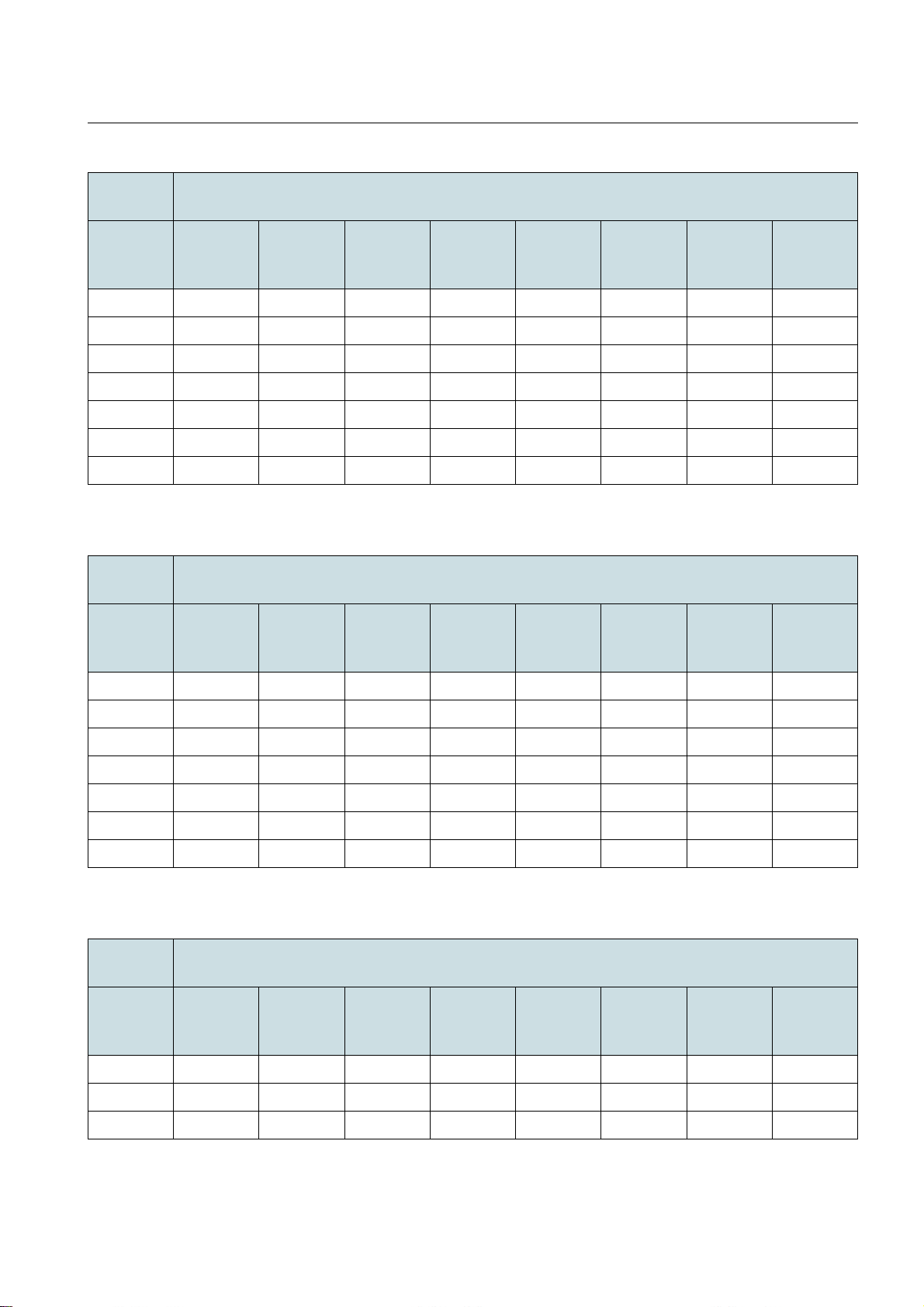
DragonWave Inc. Technical Specification
20 MHz/
Latency (ms)
GI:400 ns
MCS BPSK
Coding
1/2
QPSK
Coding
1/2
QPSK
Coding
3/4
16 QAM
Coding
1/2
16 QAM
Coding
3/4
64 QAM
Coding
2/3
64 QAM
Coding
3/4
64 3.25 3.10 3.11 1.94 2.11 2.15 2.13 1.99
128 3.35 3.28 3.36 1.97 2.11 2.08 2.08 2.16
256 3.54 3.40 3.42 1.97 2.15 2.19 2.14 2.18
512 4.09 3.54 3.55 2.07 2.17 2.21 2.17 2.17
1024 3.88 3.68 3.63 2.36 2.15 2.09 2.09 2.18
1280 4.06 3.72 3.86 2.34 2.37 2.17 2.15 2.18
1518 4.26 4.05 3.68 2.31 2.37 2.32 2.16 2.20
Table 51
20 MHz/
Latency - 70/30 Tx/Rx Ratio 20 MHz/GI:400 ns
Latency (ms)
GI:800 ns
MCS BPSK
Coding
1/2
QPSK
Coding
1/2
QPSK
Coding
3/4
16 QAM
Coding
1/2
16 QAM
Coding
3/4
64 QAM
Coding
2/3
64 QAM
Coding
3/4
64 QAM
Coding
5/6
64 QAM
Coding
5/6
64 3.26 3.11 3.12 1.98 2.02 2.15 2.05 1.98
128 3.37 3.32 3.39 2.06 2.09 2.04 2.11 2.13
256 3.55 3.43 3.40 1.94 2.04 2.22 2.19 2.18
512 4.13 3.57 3.52 1.94 2.05 2.18 2.20 2.26
1024 3.95 3.67 3.65 2.30 2.11 2.06 2.11 2.13
1280 4.14 3.81 3.83 2.38 2.39 2.23 2.22 2.19
1518 4.27 4.14 3.70 2.34 2.24 2.37 2.20 2.20
Table 52
40 MHz/
Latency - 70/30 Tx/Rx Ratio 20 MHz/GI:800 ns
Latency (ms)
GI:400 ns
MCS BPSK
Coding
1/2
QPSK
Coding
1/2
QPSK
Coding
3/4
16 QAM
Coding
1/2
16 QAM
Coding
3/4
64 QAM
Coding
2/3
64 QAM
Coding
3/4
64 3.23 3.09 3.16 2.26 2.29 2.42 2.26 2.29
128 3.43 3.16 3.21 2.17 2.24 2.39 2.36 2.40
256 3.60 3.25 3.30 2.27 2.17 2.41 2.37 2.38
64 QAM
Coding
5/6
Table 53
Latency - 30/70 Tx/Rx Ratio 40 MHz/GI:400 ns
63
Page 64
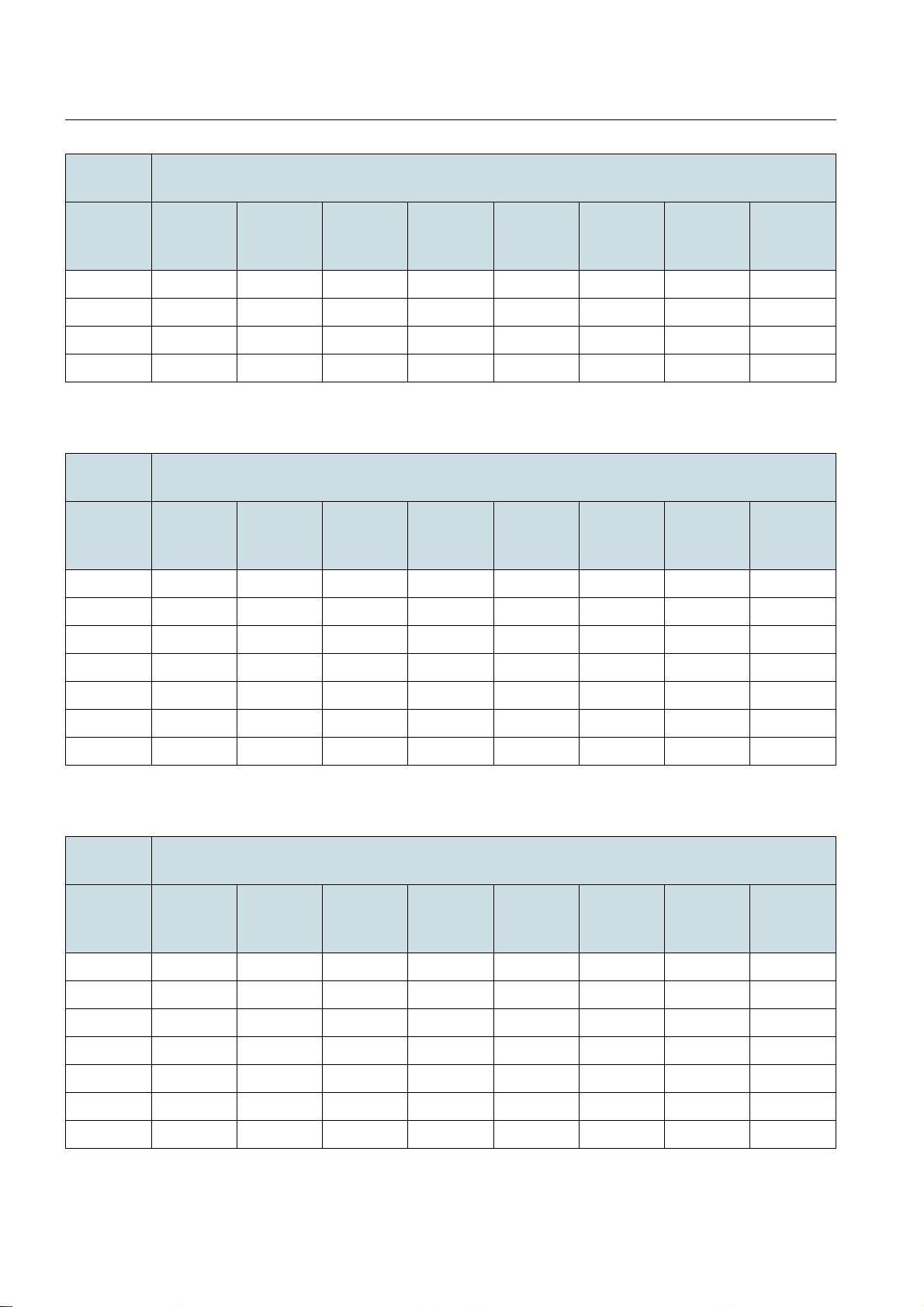
DragonWave Inc.Technical Specification
40 MHz/
Latency (ms)
GI:400 ns
MCS BPSK
Coding
1/2
QPSK
Coding
1/2
QPSK
Coding
3/4
16 QAM
Coding
1/2
16 QAM
Coding
3/4
64 QAM
Coding
2/3
64 QAM
Coding
3/4
512 3.75 3.43 3.39 2.34 2.19 2.41 2.34 2.35
1024 4.24 3.62 3.49 2.45 2.17 2.23 2.29 2.37
1280 4.31 3.76 3.60 2.54 2.44 2.37 2.34 2.32
1518 4.39 4.21 3.68 2.57 2.40 2.42 2.33 2.36
Table 53
40 MHz/
Latency - 30/70 Tx/Rx Ratio 40 MHz/GI:400 ns
Latency (ms)
GI:800 ns
MCS BPSK
Coding
1/2
QPSK
Coding
1/2
QPSK
Coding
3/4
16 QAM
Coding
1/2
16 QAM
Coding
3/4
64 QAM
Coding
2/3
64 QAM
Coding
3/4
64 3.43 3.11 3.15 2.27 2.27 2.41 2.42 2.25
128 3.42 3.16 3.22 2.23 2.25 2.28 2.38 2.35
64 QAM
Coding
5/6
64 QAM
Coding
5/6
256 3.53 3.25 3.32 2.26 2.17 2.40 2.41 2.37
512 3.96 3.43 3.40 2.35 2.29 2.37 2.40 2.33
1024 4.27 3.64 3.48 2.47 2.31 2.22 2.23 2.29
1280 4.36 3.84 3.67 2.58 2.48 2.36 2.37 2.34
1518 4.59 4.21 3.63 2.59 2.38 2.49 2.41 2.33
Table 54
20 MHz/
Latency - 30/70 Tx/Rx Ratio 40 MHz/GI:800 ns
Latency (ms)
GI:400 ns
MCS BPSK
Coding
1/2
QPSK
Coding
1/2
QPSK
Coding
3/4
16 QAM
Coding
1/2
16 QAM
Coding
3/4
64 QAM
Coding
2/3
64 QAM
Coding
3/4
64 3.91 3.33 3.28 3.10 3.15 2.27 2.25 2.25
128 4.03 3.41 3.28 3.13 3.25 2.21 2.21 2.22
256 4.62 3.53 3.45 3.25 3.35 2.25 2.24 2.26
512 4.73 3.77 3.76 3.36 3.41 2.26 2.32 2.30
1024 7.16 4.25 4.32 4.18 3.69 2.57 2.52 2.52
64 QAM
Coding
5/6
1280 8.25 4.34 4.32 4.18 3.69 2.57 2.52 2.52
1518 9.38 4.41 4.28 4.25 3.71 2.55 2.56 2.53
Table 55
Latency - 30/70 Tx/Rx Ratio 20 MHz/GI:400 ns
64
Page 65
DragonWave Inc. Technical Specification
20 MHz/
Latency (ms)
GI:800 ns
MCS BPSK
Coding
1/2
QPSK
Coding
1/2
QPSK
Coding
3/4
16 QAM
Coding
1/2
16 QAM
Coding
3/4
64 QAM
Coding
2/3
64 QAM
Coding
3/4
64 3.94 3.36 3.30 3.12 3.17 2.27 2.30 2.28
128 4.03 3.45 3.30 3.20 3.26 2.31 2.24 2.19
256 4.65 3.57 3.50 3.29 3.30 2.25 2.29 2.26
512 4.79 3.98 3.81 3.49 3.40 2.25 2.36 2.34
1024 7.21 4.32 4.31 3.67 3.54 2.54 2.48 2.45
1280 8.29 4.41 4.23 3.87 3.67 2.57 2.59 2.50
1518 9.37 4.63 4.30 4.26 3.64 2.55 2.59 2.61
Table 56
Latency - 30/70 Tx/Rx Ratio 20 MHz/GI:800 ns
64 QAM
Coding
5/6
65
Page 66
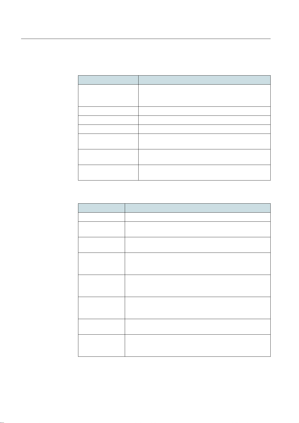
DragonWave Inc.Standards
8 Standards
Lite is in compliance with the following standards.
Recommendation Recommendation Name
IEEE 802.3-2005 Carrier sense multiple access with collision detection
(CSMA/CD) access method and physical layer specifica-
tions
IEEE 802.1Q Virtual LANs
IEEE 802.1ad Provider bridge (QinQ)
IEEE 802.1D-2004 Media access control (MAC) bridge
IEEE 802.11-2012 Wireless LAN medium access control (MAC) and physical
layer (PHY) specifications
IEEE 802.11n-2009 Wireless LAN medium access control (MAC) and physical
layer (PHY) specifications
IEEE P802.3at/D1.0 Enhanced data terminal equipment (DTE) power via
media dependent interface (MDI) enhancements
Table 57 IEEE Standards
Recommendation Recommendation Name
EN 60215 Safety Requirements for radio transmitting eq uip men t
EN 60950-1 Information technology equipment - Safety - Part 1: General
requirements
EN 60950-22 Information Technology Equipment - Safety - Part 22: Equipment
to be Installed Outdoors
EN 61000-4-2 Electromagnetic compatibility (EMC) - Part 4 : Testing and mea-
surement techniques - Section 2: Electrostatic discharge
requirements
EN 61000-4-3 Electromagnetic compatibility (EMC) - Part 4: Testing and mea-
surement techniques - Section 3: Radiated electromagnetic field
requirements
EN 61000-4-4 Electromagnetic compatibility (EMC) - Part 4: Testing and mea-
surement techniques – Section 4: Electrical fast transient/burst
immunity test. Basic EMC Publication
EN 61000-4-5 Electromagnetic compatibility (EMC) - Part 4: Testing and mea-
surement techniques - Section 5: Surge immunity test
66
EN 61000-4-6 Electromagnetic compatibility (EMC) - Part 6: Testing and mea-
surement techniques - Section 6: Immunity to conducted disturbances, induced by radio frequency fields
Table 58
CEPT standards
Page 67

DragonWave Inc. Standards
Recommendation Recommendation Name
EN 55022 Limits and methods of measurement of radio interference char-
acteristics of information technology equipment
Table 58
CEPT standards
Recommendation Recommendation Name
EN 300 019-1-1 Environmental conditions and environmental tests for tele-
communications equipments. Parts 1-1: Classification of
environmental conditions: Storage
EN 300 019-1-2 Environmental conditions and environmental tests for
telecommunications equipments. Parts 1-2: Classification
of environmental conditions: Transportation
EN 300 019-1-4 (2003-
04)
Environmental conditions and environmental tests for
telecommunications equipments. Parts 1-4: Classification
of environmental conditions: Stationary use at nonweather protected locations
EN 300 019-2-1 Environmental conditions and environmental tests for tele-
communications equipment; Part 2-1: Specification of
environmental tests; Storage
EN 300 019-2-2 Environmental conditions and environmental tests for tele-
communications equipment; Part 2-2: Specification of
environmental tests; Transportation
EN 300 019-2-4 – Environmental conditions and environmental tests for
telecommunications equipment; Part 2-4: Specification of
environmental tests; Stationary use at non-weather protected locations
EN 301 489-1 Electromagnetic compatibility and Radio spectrum Matters
(ERM); Electro-Magnetic Compatibility (EMC) standard for
radio equipment and services; Part 1: Common technical
requirements
EN 301 489-17 Electromagnetic compatibility and Radio spectrum Matters
(ERM); Electro-Magnetic Compatibility (EMC) standard for
radio equipment and services;
EN 300 132-2 (2007-10) Power supply interface at the input to telecommunications
equipment; Part 2: operated by direct current (DC)
EN 301 893 V1.7.1
(2012-06)
Broadband Radio Access Networks (BRAN); 5 GHz high
performance RLAN; Harmonized EN covering the essential requirements of article 3.2 of the R&TTE Directive
EN 302 502 V1.2.1
(2008-07)
Broadband Radio Access Networks (BRAN); 5, 8 GHz
fixed broadband data transmitting systems; Harmonized
EN covering the essential requirements of article 3.2 of the
R&TTE Directive
Table 59 ETSI Standards
67
Page 68
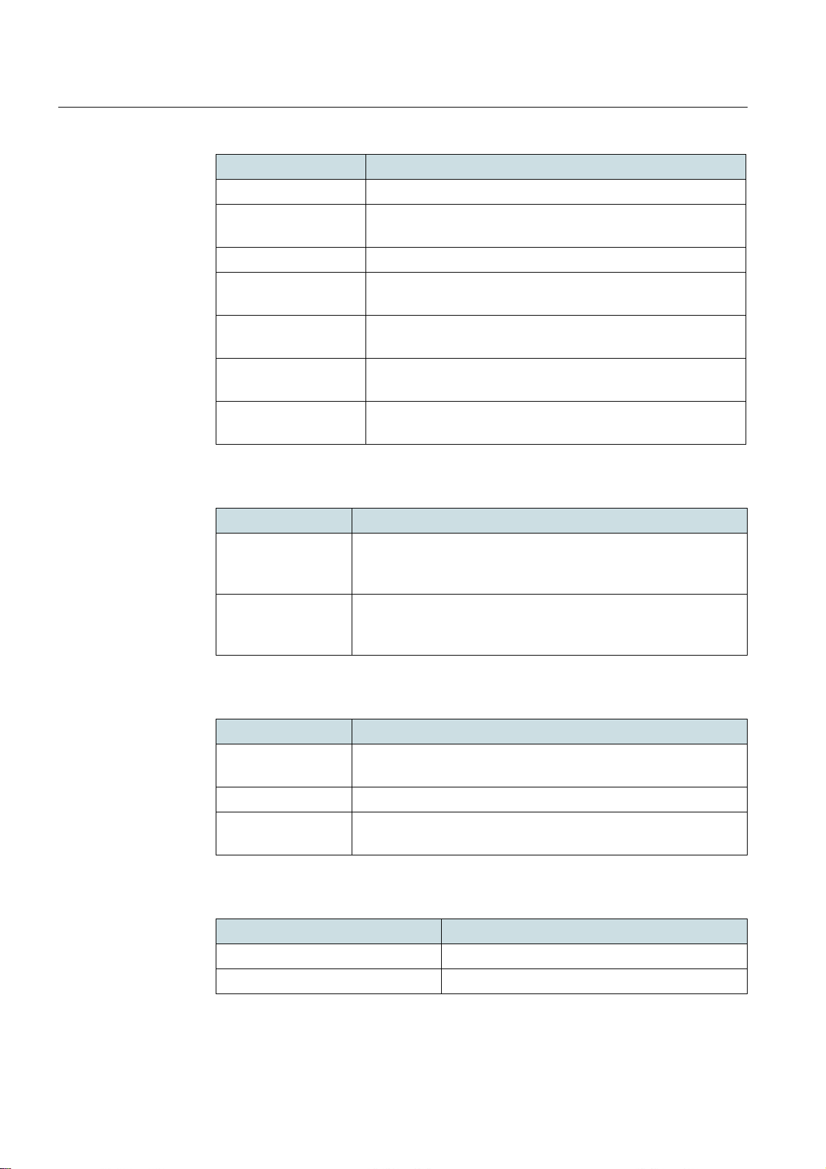
DragonWave Inc.Standards
Recommendation Recommendation Name
G.8261/Y.1361 Timing and synchronization aspects in packet networks
G.8262/Y.1362 Timing characteristics of synchronous Ethernet equipment
slave clock (EEC)
G.8264/Y.1364 Distribution of timing information throug h pa ck et ne tworks
G.826 End-to- end error performance par ameters and objectives for
international, constant bit-rate digital paths and connections
G.828 Error performance parameters and objectives for intern a -
tional, constant bit-rate synchronous digital paths
K.48 EMC requirements for telecommunicatio n eq uipm en t –
Product family Recommendation
Y.1731 OAM functions and mechanisms for Ethernet based
networks
Table 60
ITUT Standards
Recommendation Recommendation Name
EN 61000-4-11 Electromagnetic compatibility (EMC) - Part 4-11: Testing and
measurement techniques - Voltage dips, short interrup tions and
voltage variations immunity tests
EN 61000-4-29 Electromagnetic compatibility (EMC) – Part 4-29: Testing and
measurement techniques – Voltage dips, short interruptions
and voltage variations on d.c. input power port immunity tests
Table 61
IEC Standards
Recommendation Recommendation Name
GR-63-CORE Network equipment-building system (NEBS) requirement:
Physical protection
GR-478-CORE Network maintenance: Alarm and control for network elements
GR-1089-CORE Electromagnetic compatibility and electrical safety: Generic
criteria for network telecommunications equipment
68
Table 62
NEBS Standards
Recommendation Recommendation Name
CFR47 Part 15 Subpart B Class B Unintentional radiators (Digital Emissions)
CFR47 Part 15 Subpart C Intentional radiators
Table 63
FCC Standards
Page 69
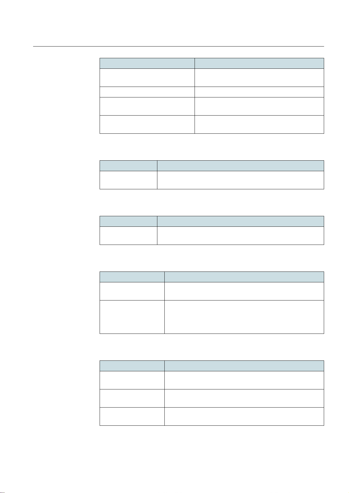
DragonWave Inc. Standards
Recommendation Recommendation Name
CFR47 Part 15 Subpart E Unlicensed national information infrastructure
devices
CFR47 Part 90 Subpart Y Private land mobile radio services
CFR47 Part 27 Miscellaneous wireless communications
services
CFR47 Part 90 Subpart Z Wireless Broadband Services in the 3650-3700
MHz Band.
Table 63
FCC Standards
Recommendation Recommendation Name
ICES-003 Information technology equipment (ITE) - Limits and methods of
measurement
Table 64
ICES Standards
Recommendation Recommendation Name
UL 50E Enclosures for electrical equipment, environmental consider-
ations
Table 65
UL Standards
Recommendation Recommendation Name
ECC recommendation
(06)04
Use of the band 5 725-5 875 for broadband fixed wireless
access (BFWA)
ECC/DEC/(04)08 ECC decision of 09 July 2004 on the harmonized use of the
5 GHz frequency bands for the implementation of wireless
access systems including radio local area networks
(WAS/RLANs)
Table 66
ECC Standards
Recommendation Recommendation Name
IC RSS-210 License-exempt Radio Apparatus (All Frequency Bands):
Category I Equipment
IC RSS-192 Fixed Wireless Access Equipment Operating in the Band
3450-3650 MHz
SRSP-303.4 Technical Requirements for Fixed Wireless Access Systems
Operating in the Band 3475-3650 MHz
Table 67
IC Standards
69
Page 70

DragonWave Inc.Standards
Recommendation Recommendation Name
IC RSS-197 Wireless Broadband Access Equipment Operating in the
Band 3650-3700 MHz
SRSP-303.65 Technical Requirements for Wireless Broadband Services
(WBS) in the Band 3650-3700 MHz
Table 67
IC Standards
70
 Loading...