

Doughpro Proluxe RECT5741 User Manual
7
(951) 657-0379
(951) 657-4594
(951) 657-0379
For 24 hour assistance please call (951) 236-7092
Note: Always follow hood manufacture cleaning and maintence procedures
2) “Never store combustible material beneath the oven, keep this are clear
at all times.”
3
4
“Improper installation, adjustment, alteration, service or maintenance can cause
property damage, injury or death. Read the installation, operation and maintenance
instruction thoroughly before installing or servicing this equipment.”
5) Duct: As with all commercial cooking equipment, Doughpro recommends
gas supply when pressure testing is equal or less than 1/2 PSI.”
Warning: Always disconnect power cord from electrical outlet before
servicing any electrical component in this oven.
never run the oven with doors in place.
six
This happens with wood burning ovens.
(951) 657-0379
(951) 657-0379
---------
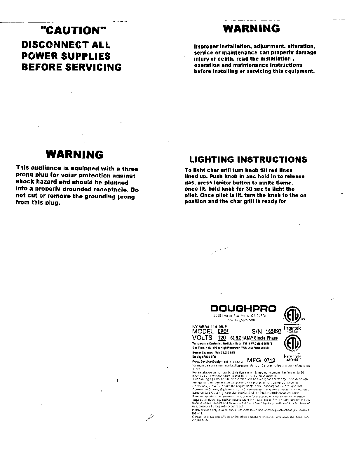
··CAUTION··
DISCONNECT ALL
POWER SUPPLIES
BEFORE SERVICING
WARNING
This
appliance
pronA
shock
pluA
hazard
into a properlv
not
cut
or
from
this
plug.
is
for
voiur
and
Arounded
remove
equipped
protection
should
the
grounding
with a three
be
pluAAed
receptacle.
aAainst
prong
Do
WARNING
ImDroper Installation. adjustment. alteration.
or
service
Injury
oDeration and maintenance Instructions
before installing
LIGHTING
To
llcaht
lined
UD.
Aas.
Dress IAnitor button
once
lit.
Dllot. Once Dilot Is
position and
maintenance can Dropertv damage
or
death. read
the
or
servicing
installation.
this
INSTRUCTIONS
char
qrlll
tum
knob
till
red lines
Push
knob In and hold In
hold knob
for
lit.
the
char
to
lanlte flame.
30 sec
tum
the
grill
Is ready
to
knob
to
light
to
for
eqUipment.
release
the
the
on
DOUGHPRO
20281
Harvill
Ave,
Perns,
','Il,,\!,/\i
a(IU9~lpro
NY MEA# 114·08·E
MODEL
VOLTS
Tlmp.rlture
O.Type:
Burner capacity:
Disploy67~OOBTU
Food
Minimum
1
inch"
Far
install:ation
eacf1
side
Tnis
COOKing
tt"le
Standard for
Operations,
Comme(C'lal
transition
Refe,
l'eqUired
building codes. Inspect
lJ~e,
creosote
In5t:~11
trtt un:t
ContoOlct
in
your
OP07
120
60
HZ
Controller: Rid
Naturale.
High
Maln7S,oOO
Service
Equipment
Clearance
fl"om combustible
on
nun-combustible
of
oven
dOor
opening
equipment
'.,,-entallation
NFPA
96,
or
COOKing
Equipment;
to 3 Class
.A.
tIO"il) required
buildup
use
only
in
blli,Cllng
grease
and
rn:ly
accorda'"rCe
officals or tire
to
manat"C'tures installation instruction fur precaution'),
air
and
local
arE2i
1AMP
Lion
Mod.tT1624
Pr.sur-e4"WClowPressuFIMin.
BTU
""''""",,
rnaterI3\~,'
flljors
anCl
36"
is
to
be
PI"O\-~deCl
Control
and
with
the
requirements
UL
71
U . .A.lternJtively it
duct
constructed
for
Imtalla!iOn
clean
tr-II?_
o"/en
IJccur
rapiW:..'
·'i'iiU""1
installation 3nd
offic.I3l:::
CA
92570
com
SIN
Single
VAC
ULffE18C.76
M
FG:
tup
only.
E;~tend
in
fn1nt
of
door
'·"'.'IU'"I
an
exuast
Fire Protection
in
me
to
1994
of
tile
e;~'aust
ind
flue
,-",llout
restricti,:j:1S,
~
Phase
QI1l
1:.
mcne=:;
sk1es
non-combustible
opening
I,'ood
testel1
Df
Corn
mer
Standard
for
may,'
be (onnecte[1
Uniform
~,:ecr(lniC3.1
c!ear
Mod
Ensure
frequently-under
Clp~r3ting
Instructions
instsli:Jlior'i
Intertek
4001284
@
Intertek
4001284
:aM tJaiJ(
fll10ring
for
compliarce
':1.)1
COOking
Exua:;t
Hoojs
',,'Id a UL
COde
anee:;
and
compliance
cert.aln
l;ondition~
pru'-1cled
and
of
t)"IC
to
30"
ror
listed
(fIlniiTIUlri
in:peUlon
ulJen
'''''''IU"I
local
witI"J
wr
Phone (951) 657-0379
Fax (951) 657-4594
Table of Contents
Oven Installation and Operation Manual
Section One:
Toll Free (800) 624-6717
Description of Doughpro Oven
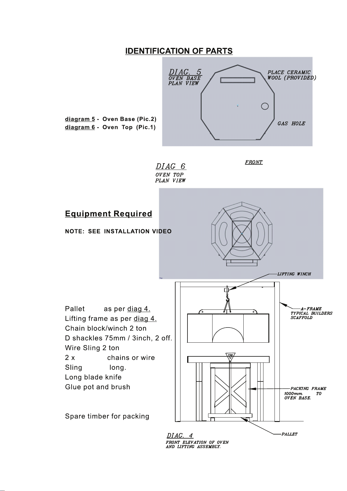
Identification of Parts
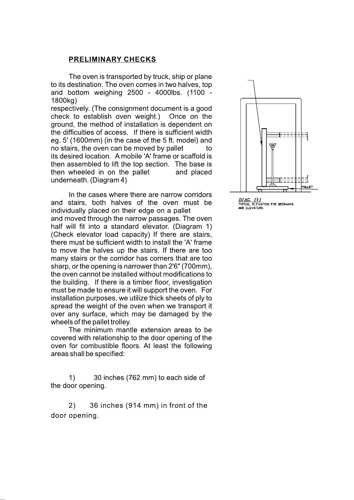
Preliminary Checks
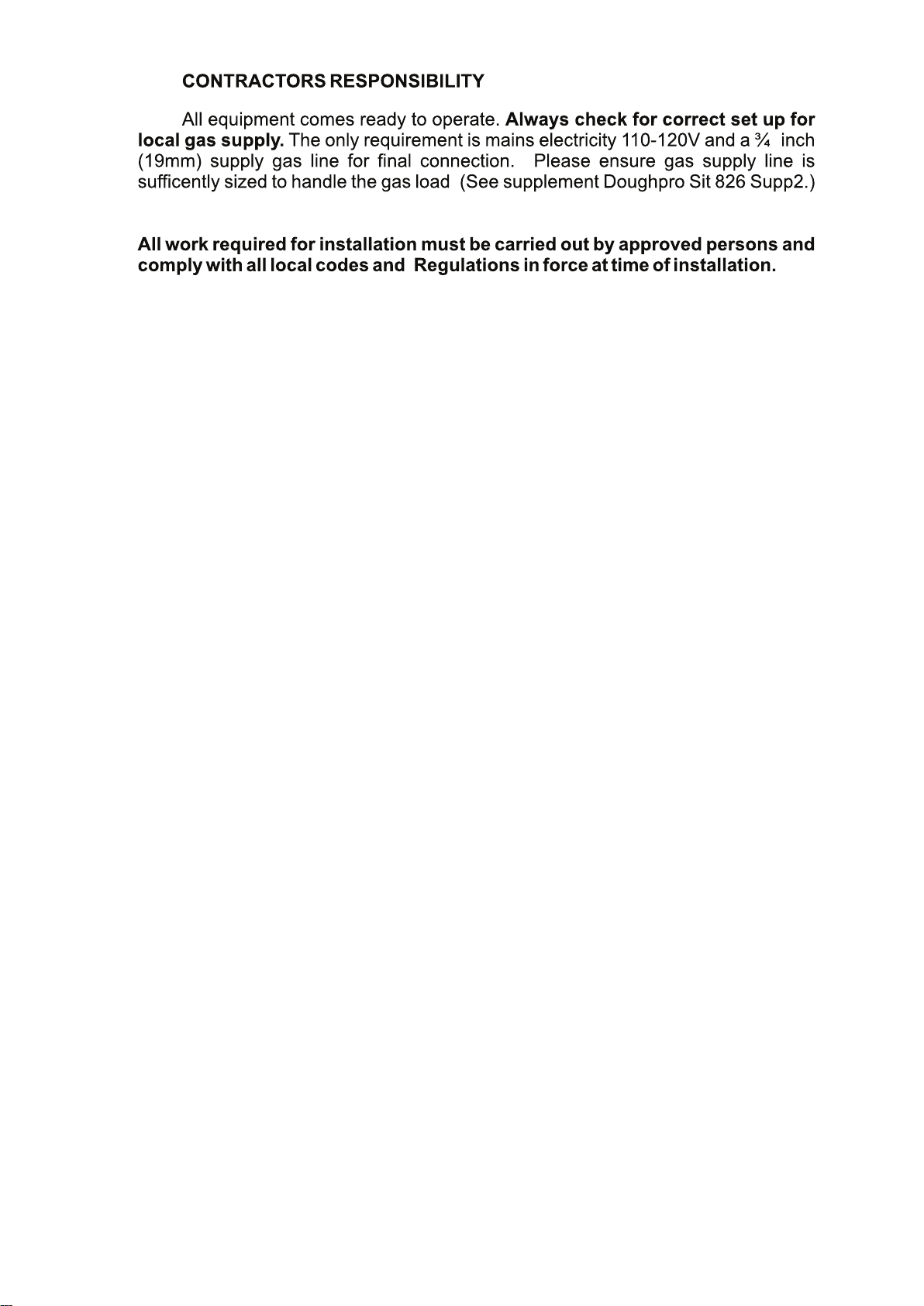
Contactors Responsibility
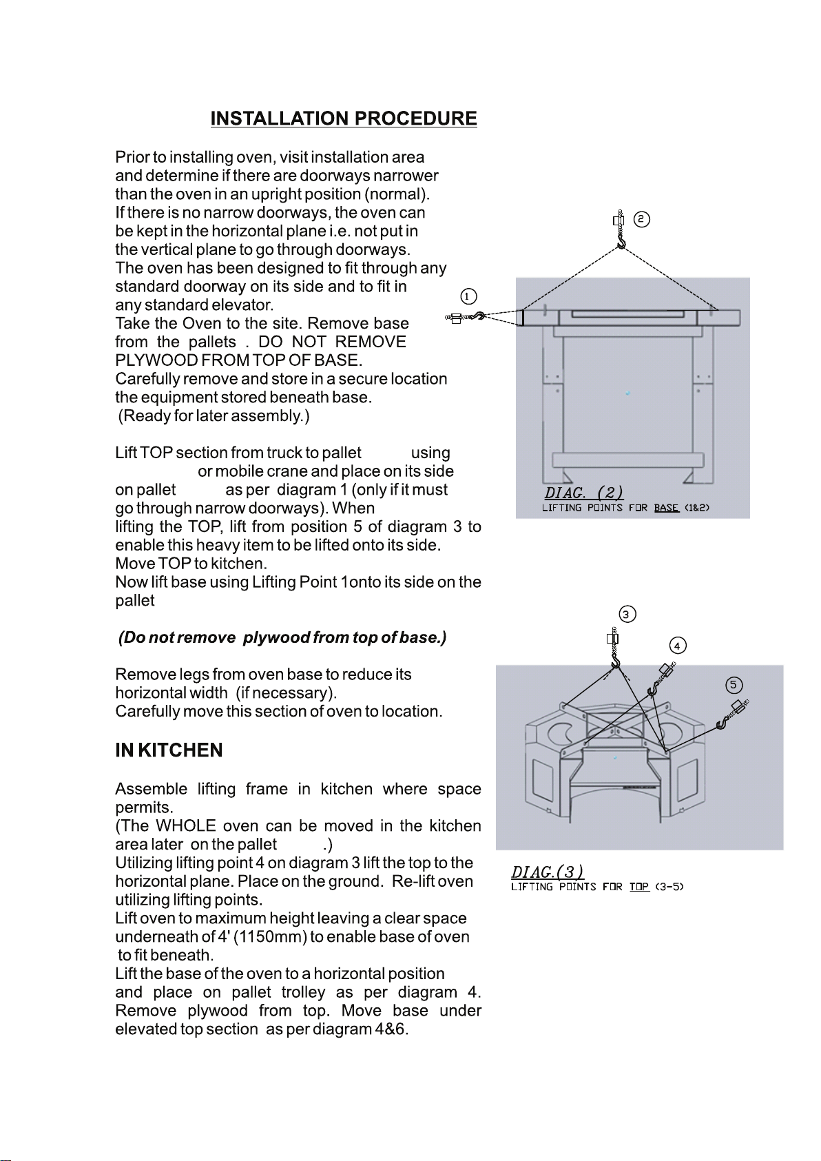
Installation Procedures
•Transportation
•Assembly
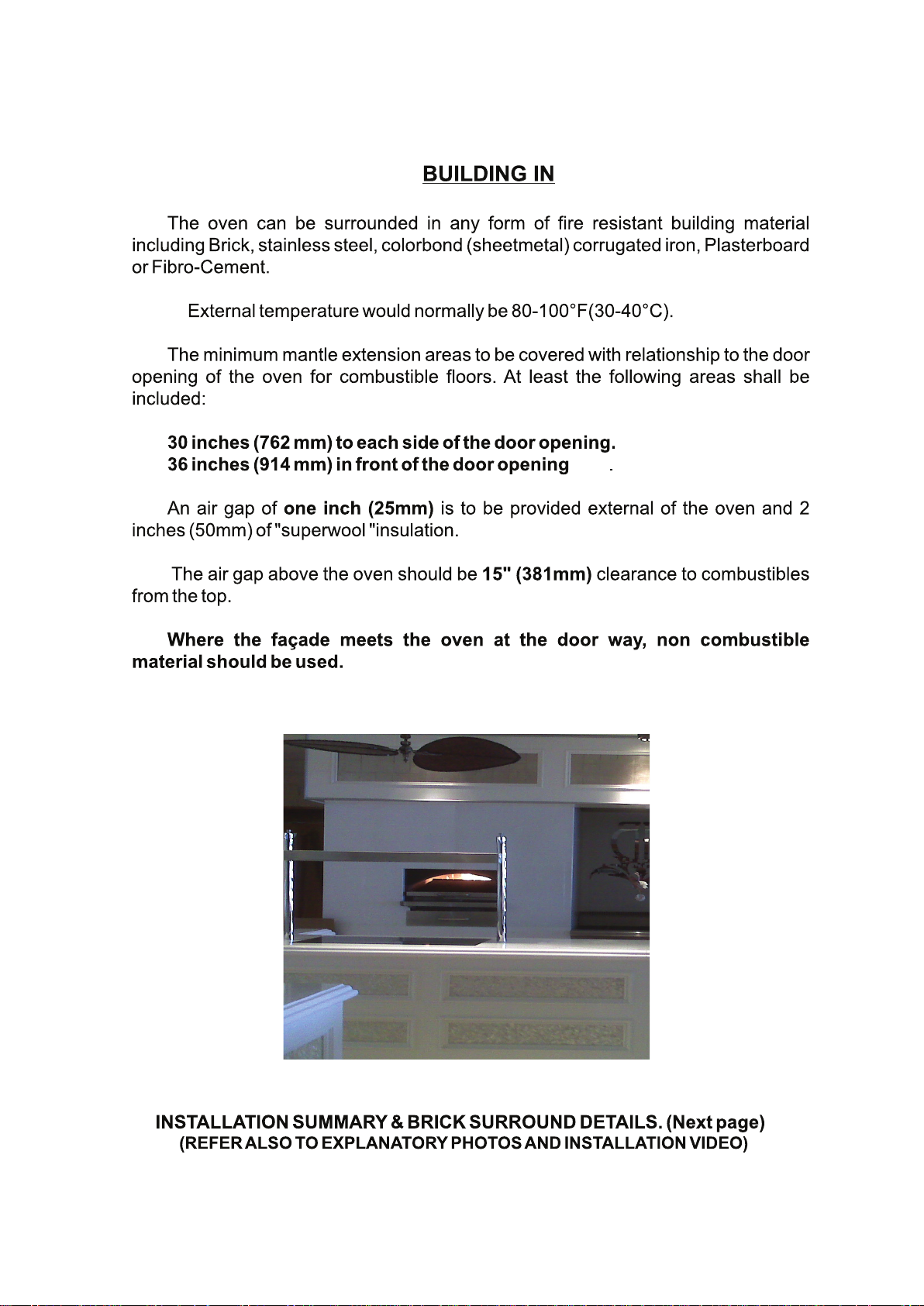
Building In
Surrounding the Oven In Brick
Oven Controls Installation
Gas System for Doughpro Ovens
•Connection of Gas System
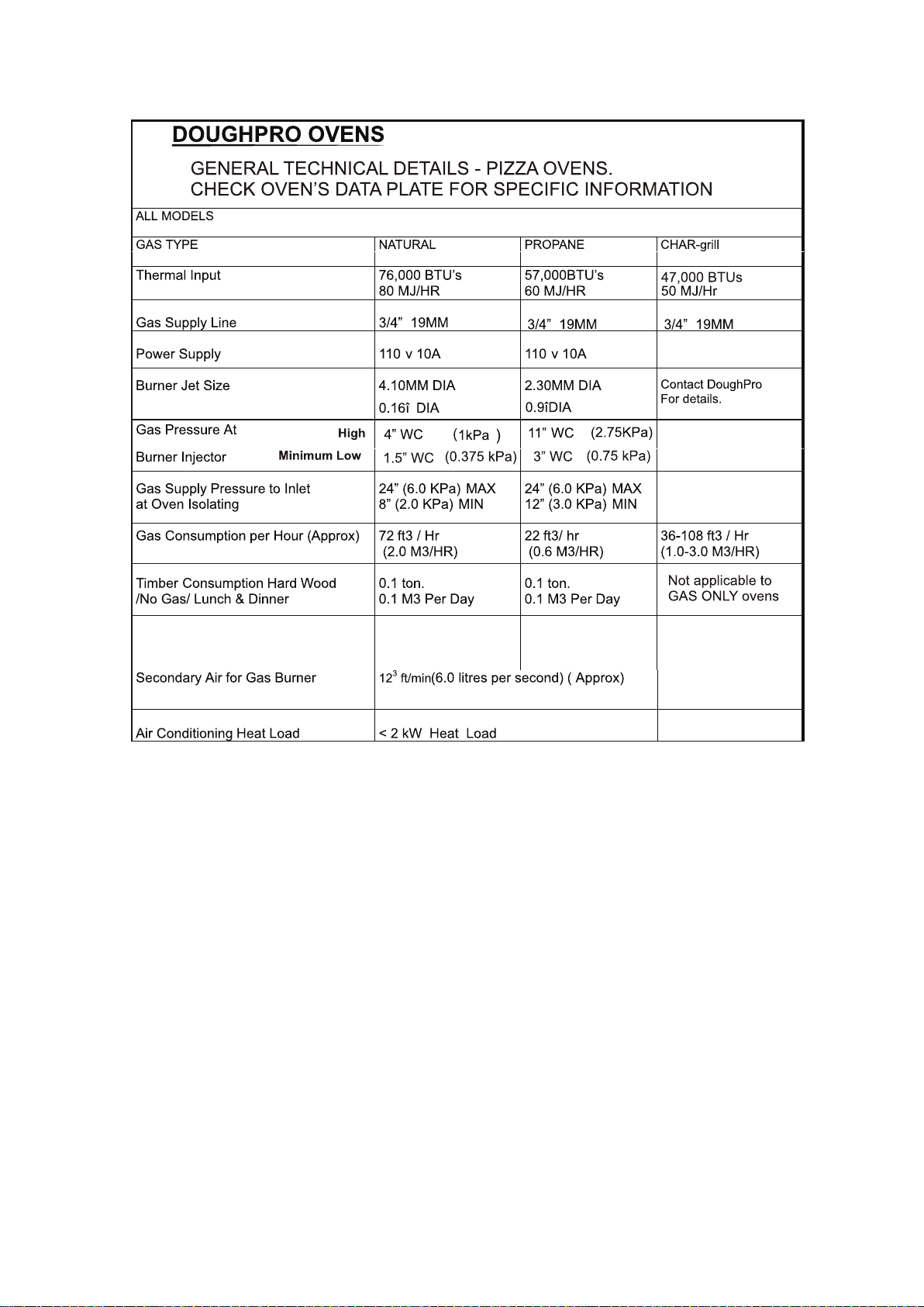
•Technical Details
•Right Flame Color
Commissioning
7
8
9
10
11
13
14
18
19
20
21
22
23
26
27
Preheat / Curing of Oven
Spare Parts List
Overview of Oven Controls
Burner Removing Instructions
Technical Details
•Single Gas Box EXP and Parts
•Oven Electrical Info
•Double Gas Box EXP and Parts
28
29
30
31
39
45
46

Section Two:
Controller Configurations
Gas Ovens
•General Gas Details
•Preheating/Cooking
•Firing up to cook
Wood Ovens
•Recommended woods
•Ash Disposal
Coal Oven
•Removing ash box
•EXP drawing/Parts list
Char-grill
•Char-grill operation
•Cleaning the char-grill
•EXP and parts list
54
59
60
61
64
65
68
69
71
72
73
Care and cleaning
Oven Venting recommendations
Oven Installation clearance
Section Three:
Oven Materials
Warranty and Return Policy
76
77
84
85
91
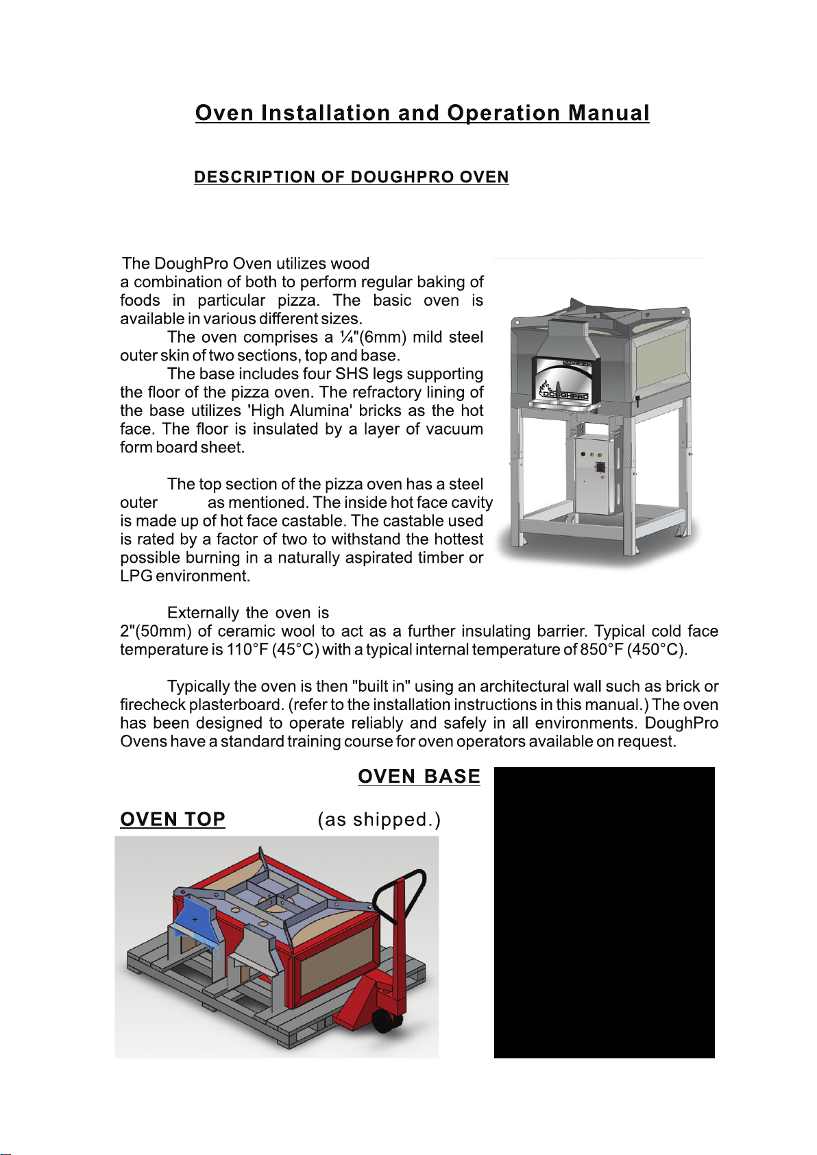
frame
,coal or gas or
to be covered in a further
7
jack
2200 lbs
10 feet
jack
JACK
8
or shipped in one piece
jack
jack
jack
jack
9
and correct pressure is available to the gas box.
Installer is responsible to make sure oven is level to the oor
10
forklift
jack
jack
jack
jack
11
NOTE: ALWAYS FOLLOW HOOD MANUFACTURES CLEANING PROCEDURES
Captive Air...
National Accounts
Captive-Aire Systems Inc.
4641 Paragon Park
Raleigh NC 27616
800/334-9256
919/882-5204 fax#
12
Doughpro
R ND- RE C- R G O Manual
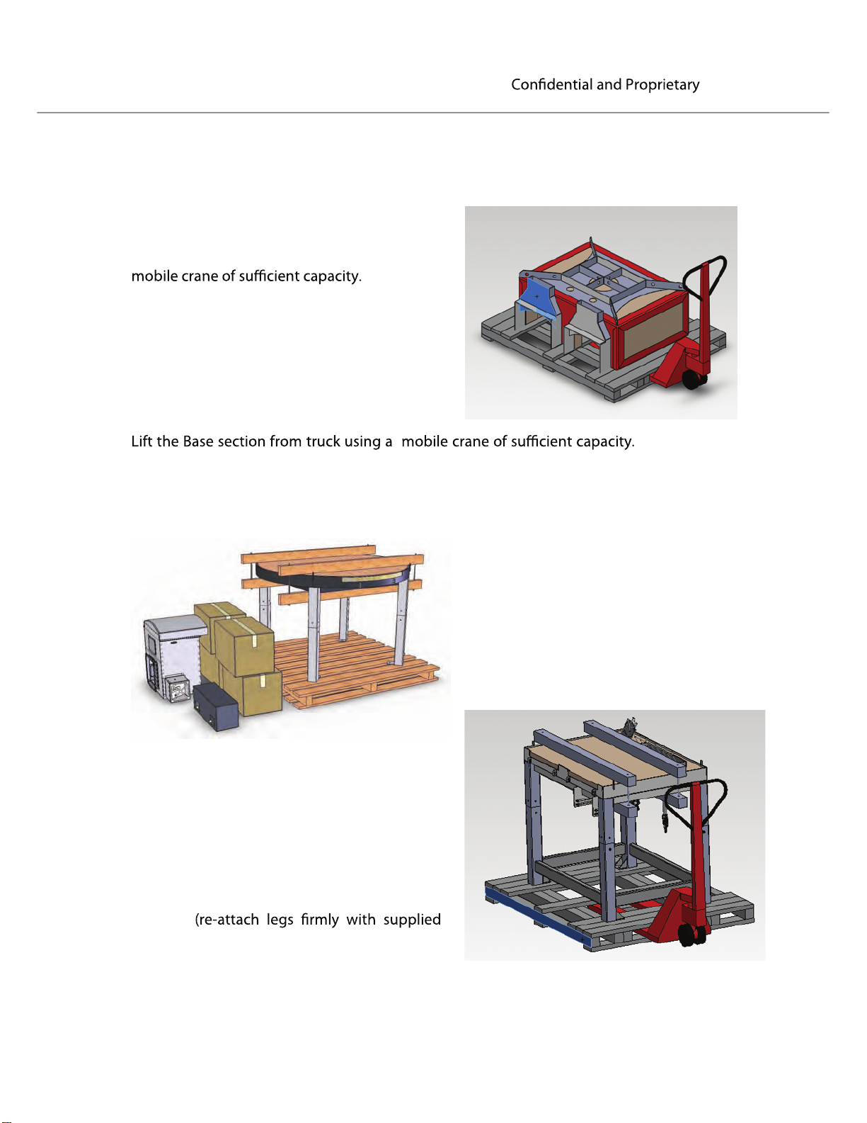
Transportation
the Oven to the site.
Take
Lift the Upper section from truck using a
Move
from pallet and place on it’s side on pallet
jack if it must go through narrow doorways See previous section - Lifting Positions )
(Remove from pallet and place on its side on pallet jack if it must go through narrow
doorways - See previous section - Lifting Positions)
Do NOT remove plywood from top of Base.
the Upper section to kitchen. (Remove
Carefully remove the equipment stored
beneath the Base and store in a secure
location (ready for later assembly).
Now lift the Base onto pallet jack. (On it’s
side if it must go through narrow doorways:
See previous section - Lifting Positions)
Remove leg
width if necessary.
Carefully move this section of oven to
location
bolts if transported on its side).
s from oven base to red
uce its
13
Doughpro
RND-REC-RGO Manual
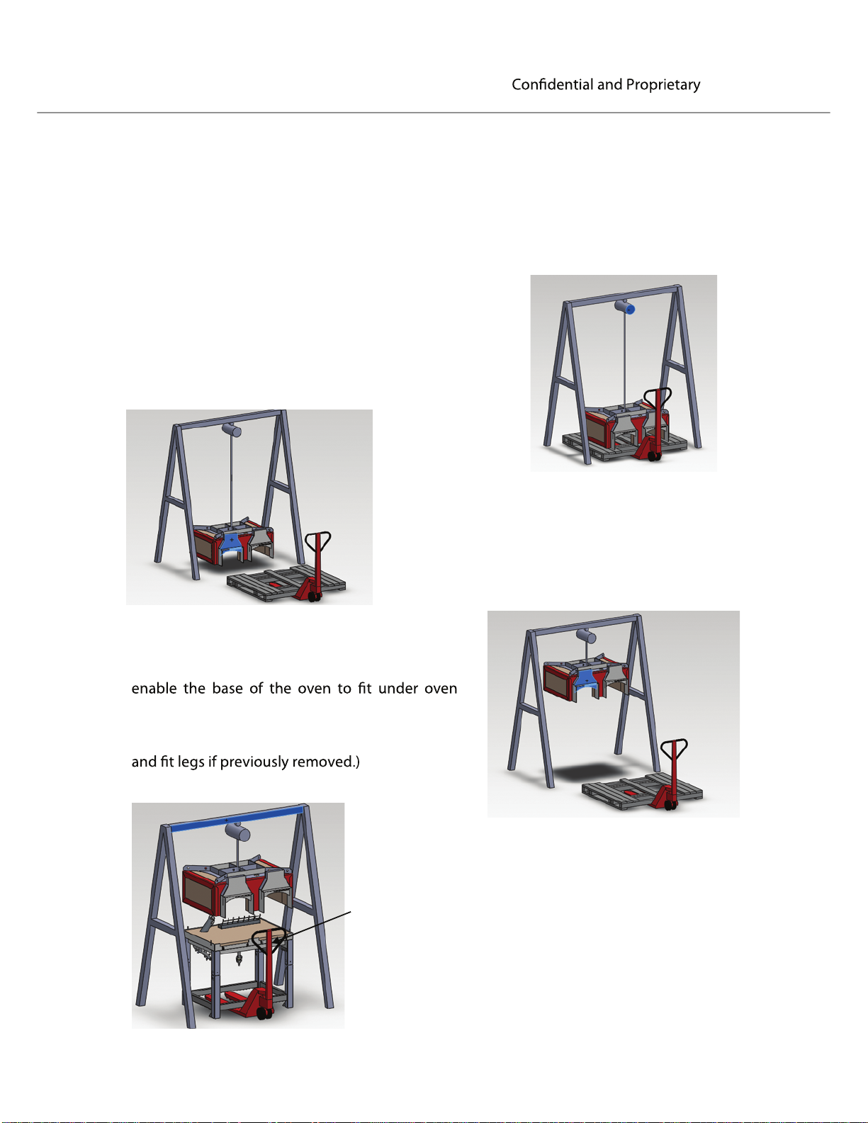
Assembly
The procedure mentioned below uses an “A-Frame” lifting method for assembling the
oven. Other lifting methods may be used e.g. a fork truck or crane, however the
following principals still apply.
Assemble lifting frame in kitchen where space permits.
(The assembled oven must be able to be moved
within the kitchen area without obstruction later on the
pallet jack.)
Utilizing lifting point 3 on previous dia
top free of the pallet and place on the ground, while
moving the base
Lift the oven top to such a height to leave a
clear space underneath of minimum 46 inches to
top.
(Lift the base of the oven to a horizontal position
Move base under elevated top section using a lifting
frame or a stack of narrow pallets, being careful not to
damage any equipment under the oven; e.g.
burners, sensors, etc.
gram, lift the
into position.
You may now remove the protective plywood from the
top of the base.
14
Doughpro
RND-REC-RGO Manual
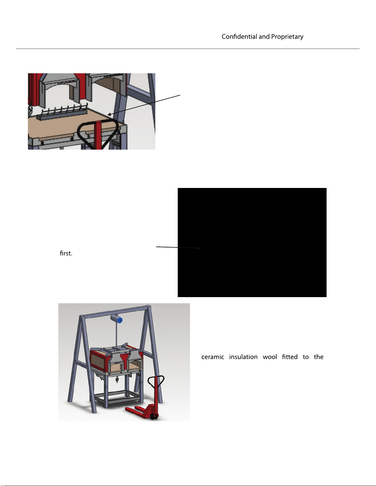
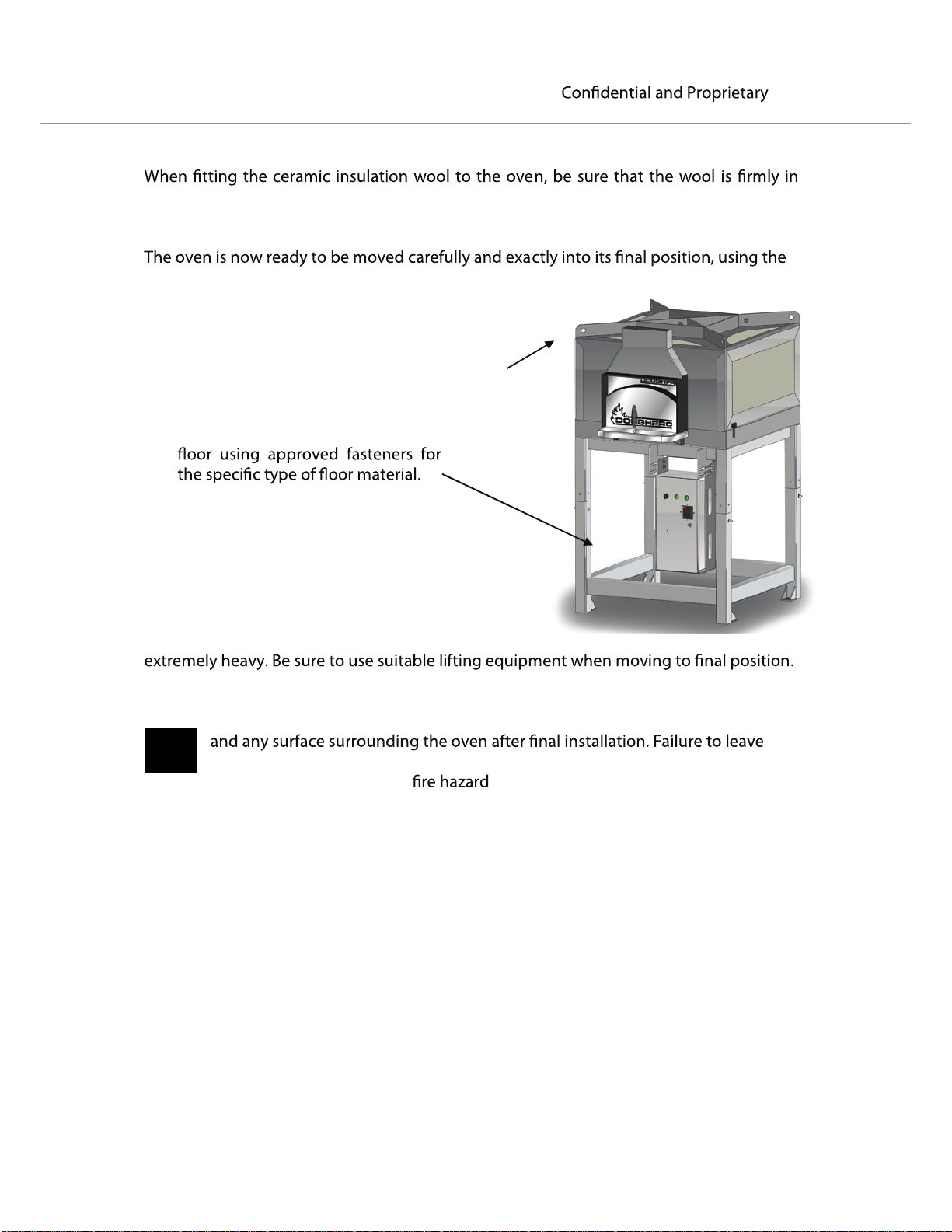
Position wool strips so that they
remain hidden when the two halves
of the oven are assembled together.
Align the top and base using
the positioning tabs welded to
the base, locating the rear tab
Ensure that the oven
mouth aligns with the cutouts in the base.
Place strips of 2 inch x 1/2 inch ceramic
insulation wool (supplied) beneath the top of
the oven where the top section touches the
base.
NOTE: No wool should come between the
steel of the top and base.
With the two halves together the oven is
now ready to have the supplied 2 inch
external surfaces.
The “A-frame” can now be dismantled
and removed.
15
Doughpro
RND-REC-RGO Manual
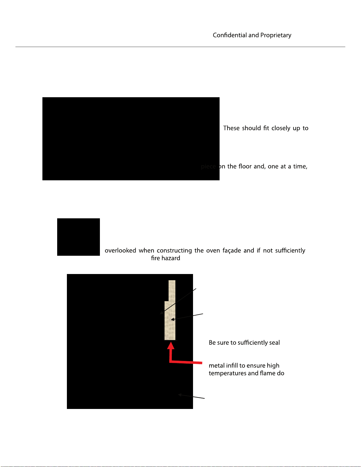
The external surfaces (sides and top) of the oven are then completely covered with
ceramic insulation wool ( 2 inch Superwool ) using the high temperature Blox Stix glue
provided.
First cut all pieces
required to cover the sides
and top using a sharp knife.
each other with no visible gaps
to allow heat to escape.
When all pieces are cut, place each
apply a generous coat of Blox Stix glue
to the wool as shown using a trowel or
similar application tool.
An important area to be aware of is directly in front of the exhaust
spigot of the oven. If the façade protrudes from the spigot there may
be an area between the spigot and the façade which is left uncovered
and vulnerable to soot and grease build up. This area is commonly
sealed creates a .
Exhaust Spigot
Insulation between spigot
and façade face
the area between the exhaust
spigot and the façade with a
not enter the façade cavity
Façade face
16
Doughpro
RND-REC-RGO Manual
place and that all air pockets are removed. The glue will dry in approximately one (1)
hour depending on ambient conditions.
lifting frame and a pallet jack (or similar).
If required, fasten the legs to the
NOTE: Fully assembled the oven can be
1 inch Air Circulation Gap
NOTE: INSTALLER IS RESPONSIBLE TO MAKE SURE OVEN IS PROPERLY LEVEL
NOTE: A 1 inch Air Circulation Gap is to be left between the ceramic wool
this air gap will result in above normal temperatures being transferred to
exterior surfaces, causing a
.
17
18
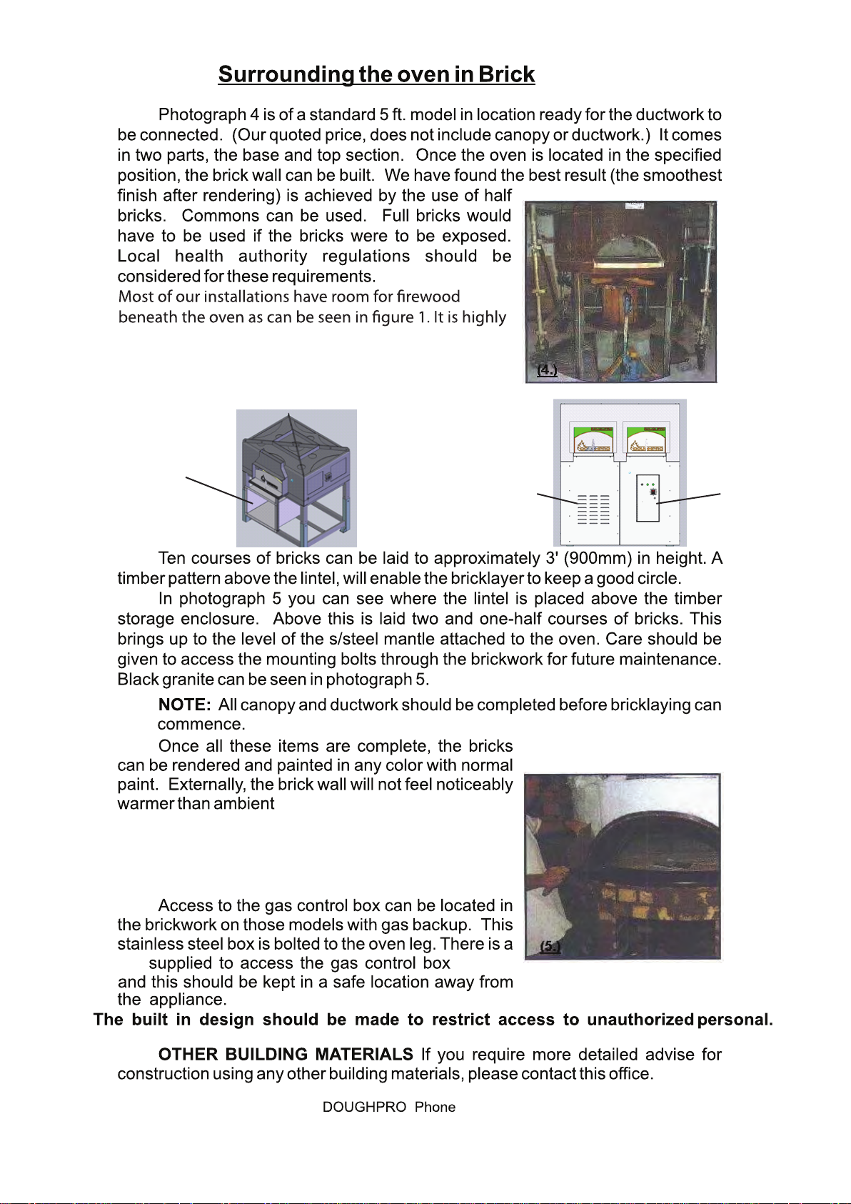
recommended that a wood box be purchased with the
oven; Doughpro heavy duty stainless steel wood box
can help you storing the wood that is going to be used
throughout the day.
Figure 1 Figure 2
Wood box
Access panel
If the oven installed is gas red, an access area must be
left for access to the gas equipment and to enable the
ingress of air to the burners. A mesh panel of 16”x16”
minimum can be incorporated for this ventilation.
Gas box
key
(951) 657-0379
19
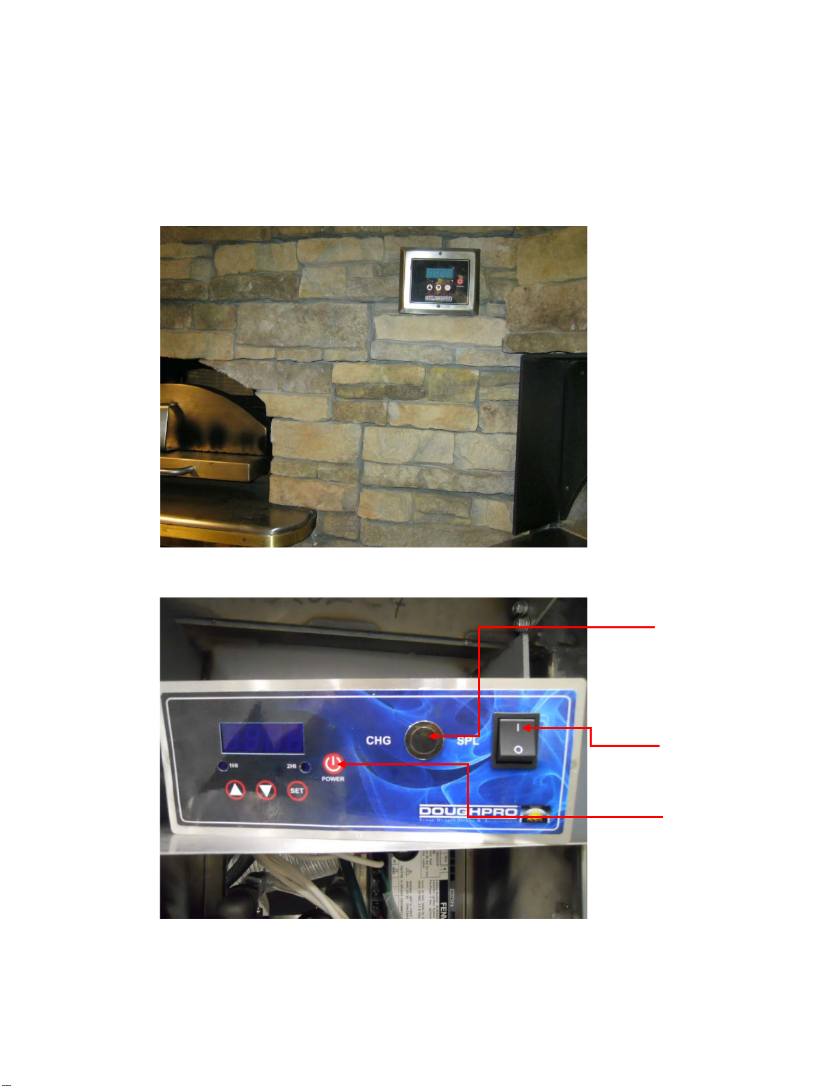
noitallatsnI slortnoc nevO
Install remote controller in a location no further the 6ft it is up to the customer's discretion to install
where they want
Depending on the oven configuration the control might a little bit different than the control shown
below.
It is up to the installer to make sure digital control is properly secure when installing the oven.
If digital control needs to be replace or service contact Doughpro
Install digital controller no further than 6ft from the center of the oven
Char grill igniter
button
Spot light
on/off switch
Controller
on/off button
Controller with char grill and spot light configuration
20
NOTE: GAS TECH SHOULD BRING IN A SINGLE INLET TO SUPPLY GAS SYSTEM AND CHARGRILL
Refer to page 21, 22
21
Stainless Steel
as well as granting access to the gas system.
3/4”
22
23
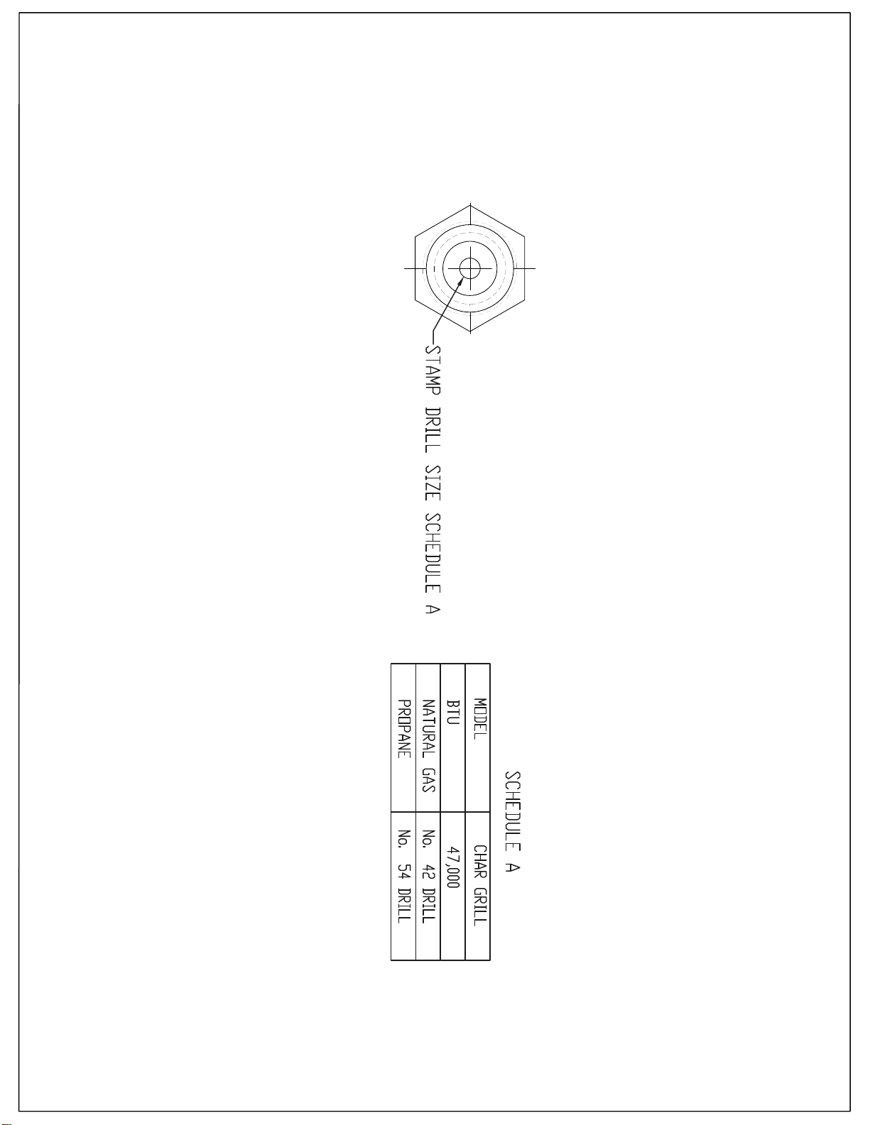
CHAR GRILL ORIFICES SIZE
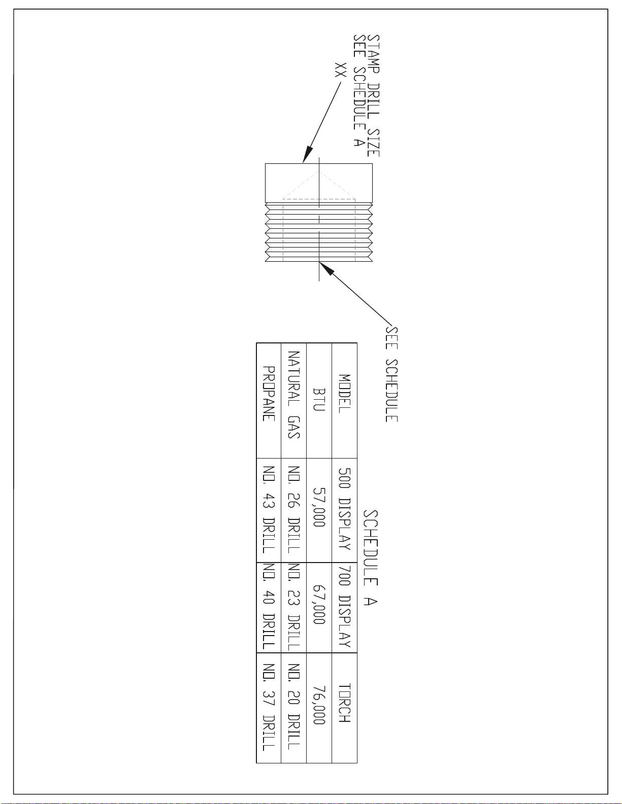
DISPLAY AND TORCH BURNER ORFICES SIZE
RIGHT FLAME COLOR
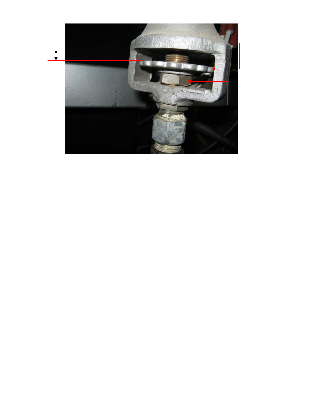
air shutter
In order to have a good combustion for your oven, the mixture of air and gas has to be right, the flame
on either torch or display burner can tell you if the mixture of these two elements is been achieved.
0.400"
locking nut
A yellow flame means that there is not enough air mixing with the gas causing a poor combustion on
either burner.
A blue flame means that there is too much air in gas mixture.
Blue color and ½ inch of yellow on the tip means that there is enough air and gas mix together to obtain
a good combustion.
All ovens are calibrated to make sure there is a good combustion of oxygen and gas, a gap of .400” is
set between the venturi and
amount of air is not enough or is too much, the air shutter and hex nut have to be move up or down; by
moving the air shutter down the amount of air going through the venturi will increase, by moving the
air shutter up the amount of air will decrease, make sure locking nut is also adjusted.
the flat washer and it is properly lock by a hex nut. In cases where the
26
jack
200 °F
27
(3)
 Loading...