

Operations Manual
Model: DP2350BZ
Automatic Dough Press
formerly DOUGHPRO. New Name. Same Quality. Superior Service.
proluxe.com
Congratulations!
2/10
Perris,
Your selection of the Doughpro DP2350
is a sound business decision. Doughpro
equipment is a result of the highest
quality engineering and time-tested
design. Your machine, combined with
Doughpro’s reputation of innovation in
dough press equipment manufacturing,
insures the continuing capability of
delivering the best-decorated product
possible.
This manual describes installation,
operation, and maintenance procedures
for your new model DP2350.
Your model DP2350 machine will have
a long trouble-free life. Read this
manual carefully and keep it with your
machine; it’s your key to proper
operation and lasting service.
Installation
DOMESTIC
Use a separate 30 amp AC
circuit. Only industrial extension
cords with proper wire size
should be used; size 16/3 wire for
distance up to 25 feet, and size
14/3 for distance up to 50 feet.
INTERNATIONAL
Use a designated 30amp AC
circuit. Only industrial extension
cords with proper wire size (2.5
sq. mm) shall be used.
Make sure there is a proper electrical
wall outlet located within reach of the
cord and plug attached to the press.
Then place the press in an area which
allows for “swing clearance” of the
lower platen plus vertical and horizontal
clearance of the press itself.
Limited Machine Warranty
conditions, to be free from
manufacturing defects in material and
workmanship for a period of one year on
parts and labor from the invoice date.
This warranty will be effective only
when Doughpro authorizes the original
purchaser to return the product to the
factory in South Gate, California freight
prepaid and only when the product, upon
examination, has proven to be defective.
This warranty does not apply to any
machine that has been subjected to
misuse, negligence or accident.
Doughpro shall not be liable for the
injury, loss or damage, direct or
consequential, arising out of the use or
the inability to use the product.
No claim of any kind shall be greater in
amount than the sale price of the product
or part to which claim is made.
This is the sole warranty given by the company, it is in
lieu of any other warranties, expressed or implied, in
law or in fact, including the warranties of
merchantability and fitness for a particular use, and is
accepted such by the purchaser in taking delivery of
this product.
Specifications
Electrical:
208V/50-60Hz/4600W/22.11Amps
Includes 72” cord and NEMA
approved plug.
Shipping Weight:
200lbs. (91kg.) – DP2350
Safety Summary
WARNING
In case of power cord damage,
do not attempt to repair or
replace the power cord. Contact
the manufacturer or the local
distributor.
Doughpro warrants this dough press
machine, when operated under normal
-1- DP2300 2/04
2/10
WARNING
Avoid touching hot surfaces
while operating the machine.
CAUTION
During normal operation, the
base of the machine must be
installed or placed above the wall
socket.
CAUTION
When servicing or cleaning the
machine, make sure that the
power cord is removed from the
wall socket.
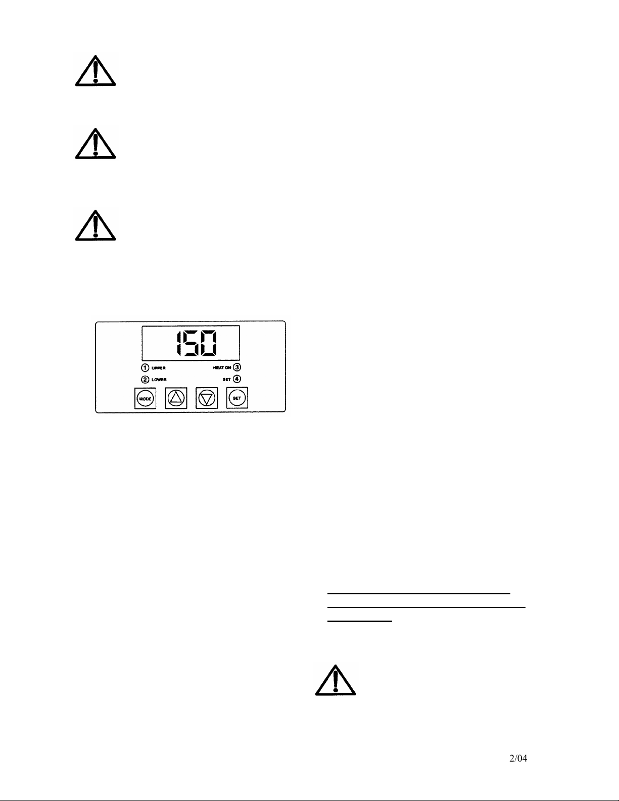
Operation Timer/Temperature
Control
Fig. A
Solid State Controller
This controller has three (3) control
features:
1. Temperature – May be set from
100°-425°F (38°-163°C)
2. Time – Time may be set from 1
second to 10 minutes.
3. Counter – Cycle counter counts
the number of applications from
1 to 9999 (see additional Notes –
Counter).
4. “2Lower” (Fig. A) Refers to
models using upper and lower
heated surfaces.
Controller Operation
1. Viewing the Modes of Operation:
-2- DP1300 2/04
4. Resetting the Counter
PRESSING DOUGH:
For best results, your dough should be
proofed before pressing, but it will also
press directly out of your refrigerator.
Flour is not required to press a crust
and should not be dusted on any part of
the machine.
• To view the set points of
temperature, timer and counter,
press MODE button to view the
desired mode of operation.
2. Changing Temperature:
• Press MODE button until
temperature is displayed.
• Press and hold SET button
while pressing the UP (↑) and
DOWN (↓) arrow buttons to
desired temperature setting.
3. Changing Time:
• Press MODE button until time
is displayed.
• Press and hold SET button
while pressing the UP (↑) and
DOWN (↓) arrow buttons to
desired timer setting.
The DISENGAGE switch may
be pressed anytime during a
cycle, and the cycle will stop
immediately, and the timer will
reset.
• Press MODE button until the
counter is displayed.
• To Reset the Counter (# of
Cycles), simultaneously push
UP (↑) or DOWN (↓) arrow
buttons (approx. 5 seconds).
WARNING
Press must be level on counter or
table in order to function properly

*
2/10
1. Switch the DP2350 to the ON
position.
Note: Initial temperature setting of
150°F has been shown to be acceptable
for most dough formulations; however,
you may have to determine the best
temperature for your own dough by trial
and error testing of your product at
different temperature settings.
2. Set the timer in accordance with
the following information:
2-4 seconds –For warm dough
with moderate yeast content.
2-6 seconds – For room
temperature dough with
moderate yeast content.
6-8 seconds – For cold dough
right out of the refrigerator with
low yeast content.
Remember that the timer does not
actuate until the upper platen mates
with the lower platen and resistance
is felt.
3. Set the thickn
“thick” or “thin” or anywhere in
between these settings as your
product requires. Models with molds:
Note: 7KLFNQHVVLVGHWHUPLQHGE\VWDQGDUG
RUFXVWRPPROGGHSWK
4. Swing open the upper platen and
apply a quick spray of a good
water based food release on the
ess control lever to
5. Place your pre-portioned ball of
dough in the approximate center
of the lower platen. Add another
dash of spray to the top of the
dough ball.
6. Close the platen and, with both
hands, press the two green
buttons on each side of the
machine simultaneously.
7. Hold the buttons in until
resistance is felt then release at
once. The timer will actuate and,
when the time cycle is
completed, the upper platen will
rise automatically (timer is preset
at factory for six (6) seconds, but
this is easily changed by
following the upcoming
instructions.)
8. Remove the crust, place on a
disc, screen, pan or peel, add
toppings and bake.
ADDITIONAL NOTES:
Serial Tags
-3- DP2300 2/04
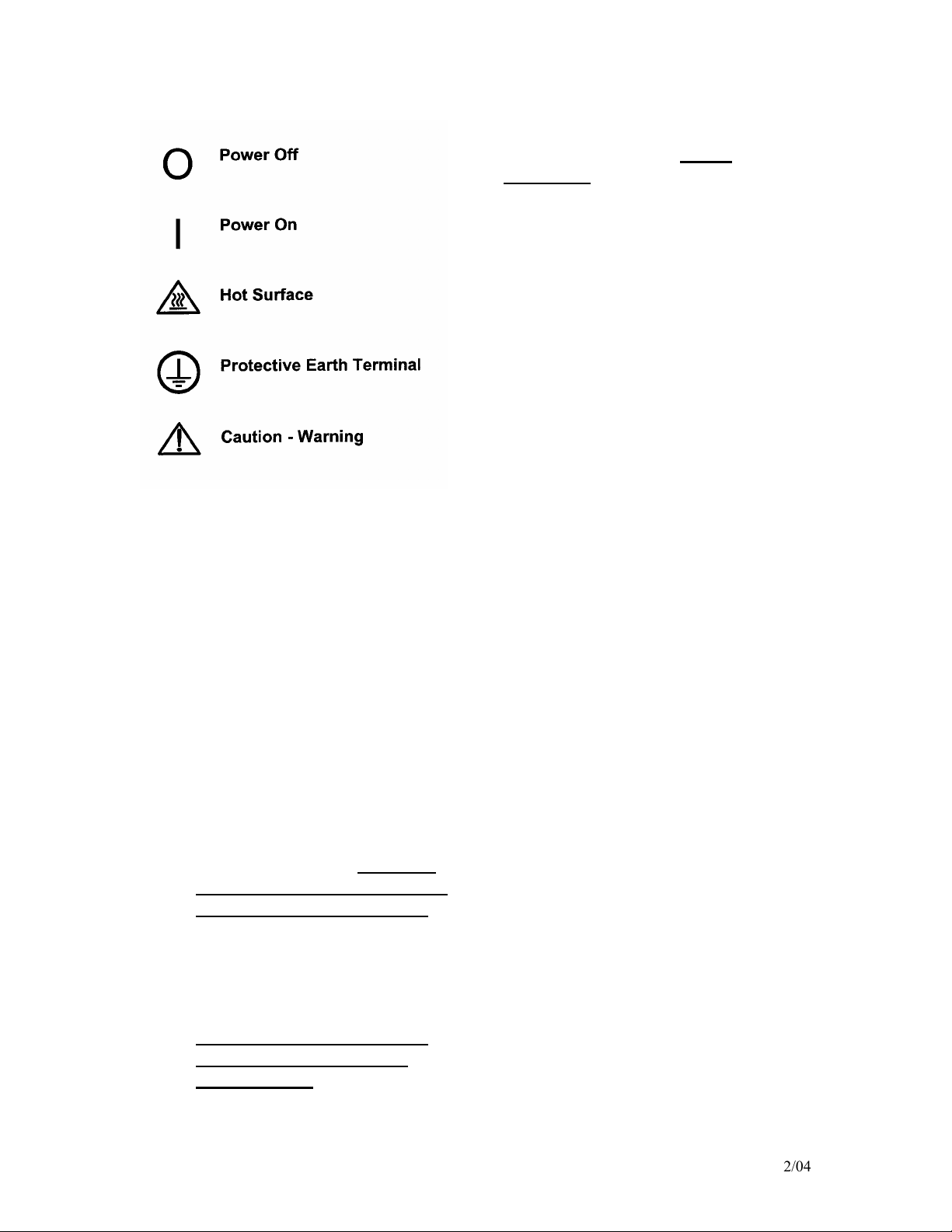
International Symbols
2/10
Preventative Maintenance Suggestions
The Doughpro DP2350 machines are
relatively maintenance free. For a long
and trouble-free life, the following
preventative maintenance should be
followed:
Daily Care:
1. Platens: Turn your machine off
and allow to cool down before
attempting to clean. These
platens should only be cleaned
with mild soap and warm water
then wiped off with a clean, soft
cloth or soft sponge. Never use
steel wool or harsh abrasives or
you will cause costly damage.
2. All other exterior surfaces:
Here again a daily wipe down
with mild soap and warm water
will do the job quite nicely.
Never use steel wool or harsh
abrasives or you will cause
costly damage.
Service Problems:
-4- DP2300 2/04
Contact our factory or approved service
agency (800) 624-6717 (U.S. only).
Note: When contacting factory for
information, parts or service
instructions, it is of the utmost
importance that the serial number of the
machine be provided. This number can
be found on the serial plate located on
the rear of the machine.

DOUGHPRO
Symptom Probable Cause Action to be Taken
Ref. #'s on
Explosion
Drawing
Power Button on Digital Controller
face is depressed but doesn’t turn
on.
Power Cord is not plugged in.
Plug power cord into wall 's
receptacle and depress power
button on controller
60
Circuit Breaker is tripped off in the
site's breaker box
Reset circuit breaker that the Grill is
plugged into. Depress Power Button
to turn on.
___
Transformer has taken a electrical
surge and is damaged
Replace Transformer after you check
secondary side of transformer. If
working properly, you should
receive 12vdc.
66
Check voltage on the secondary side
of the Transformer. If you read
12VDC then you are receiving voltage
to the Controller.
Replace Controller. Controller
should be on once the power button
is depressed.
76
Possibly blown Fuse Replace fuse.
39
Digital Controller's LED's are
scrambled or randomly irratic. If
when turning on, the display will
first go to segment check
Possibly a componet on the Digital
Controller is damaged
Replace Digital Controller
76
Possibly control needs to reset
While unit is on (controller lit up)
Unplug unit, wait for 1 min. then
plug machine on and depress power
button.
___
Digital Controller on startup goes
through LED segment check (8888)
then to version # and then loops
back to to the above reboot.
The relay driver on the digital control
may be blown.
Replace Digital Controller.
76
Digital display shows PROB. No
heat on Upper Platen.
Sensor lost it's continuity as shown
on a muti-meter.
Disconnect prob that is open (no
continuity as shown on a multimeter. Must replace Sensor (RTD).
Do not cut and splice new sensor.
Install new 2000 ohm RTD sensor to
under side of Heat Platen and
reconnect to Controller.
A1.10
When depressing the tactile button
on Digital Controller, nothing
happens.
The tactile buttons under the overlay
may be not close enough to activate.
Same goes if the buttons are already
pressed by overlay without
depressing button.
Carefully (no too much at one time
to avoid fracturing the traces on the
Controller) tighten the nuts on the
back of the Controller until button
activate. Same goes in reverse if
buttons are held down by the
overlay.
___
Digital display shows Rela and
Particular zone is over heating or
outer zone).
The Relay on the switched side is not
opening to regulate temperture.
Replace the Relay.
55
Beeper not functioning or
intermitten beeper sound.
Beeper on Digital Control board
failed.
Replace Digital Controller board
76
1
DP2350 Automatic Air Press Trouble Shooting Guide

DOUGHPRO
Symptom Probable Cause Action to be Taken
Ref. #'s on
Explosion
Drawing
If setpoint is reached but slighty off
in temperature.
Offset may need to be calibrated and
adjusted.
Must call (800) 624-6717 ext. 129
for confidential instructions.
___
Press does not close when pressing
the two, green, start buttons
Did not simultaneously press the start
buttons exactly at the same time
Try pressing both buttons eactly at
the same time. This is a anti-tiedown safety feature.
82
The Lower Platen switch mounted on
the base is not in contact to complete
circuit
Make sure the roller plunger comes
into contact (clicking noise). This is
also a safety feature that both
platens are aligned before
Heater Platen overheating
If the Relay (depending the year of
the model) on the coil side are
receiving 12vdc indicates the
Controller is functioning properly. On
the switching side of the relay, is
there 120 vac going to the heater in
question . If there is no voltage on
the to the switching side of the relay
to the heaters, the Relay is not
working properly
Replace Relay If the Controller's
heat-on LED is not lit indicating the
controller is working properly.
55
___
Both Upper and Lower Platen not
aligned when activating. You may
experience a shifting of the platens
when coming into contact, or
striking noise.
Upper and Lower Platen misaligned.
On the left side of the Post Collar
(#35) are back- to-back set screws.
Remove the first locking set screw.
Adjust stopping set screw to align
platen (*IMPORTANT* must reduce
air pressure to a minimum as not to
damaging closing platens). After
alignment is complete, re-install
locking set screw as not to move the
alignment set screw.
17
2
DP230 Automatic Air Press Trouble Shooting Guide

EXPLOSION VIEW
DP2350MBZ (MLBZ/MRBZ)
82
06/07/19
29
80
81
29
92
28
28
27
82
4X
31
A1
84
A2
86
87
90
89
55
79
93
94
85
87
88
89
91
42
62
4X
50
8
61
43
48
32
51
74
2X
59
32
4X
28
29
80
33
30
33
4X
47
4X
14
33
4X
55
4X
9
40
4X
105
4X
73
20
60
3X
4X
118
117
87
121
2X
78
77
37
25
7
66
2X
2X
93
2X
119
120
122
2X
14
8
41
38
39
34
103
24
23
21
22
124
2X
123
113
2X
36
2X
35
72
94
A4
95
93
55
90
89
87
96
97
A3
91
88
79
89
87
86
84
58
98
102
18
17
16
1
101
70
79
67
6X
68
4X
69
4X
2
107
112
71
65
2X
79
3X
64
104
70
3X
EXPDP2350MBZ (MLBZ/MRBZ) RE 060719
CUSTOMER MANUAL

116
INCLUDE PLATEN
136
75
INSIDE CRATE
76
11
6
8
4X
9
8X
100
5
50
8
51
74
8
74
4
16
3
18
17
16
67
16
63
15
52
12
10
2X
114
2X
57
4X
109
4X
74
4X
14
125
115
110
2X
100
126
44
56
56
108
106
100
53
83
111
99
54
8
4X
45
4X
46
4X
EXPDP2350MBZ (MLBZ/MRBZ) RE 060719
CUSTOMER MANUAL

PROLUXE PARTS LIST FOR
DP2350MBZ (MLBZ/MRBZ)
DP2350MBZE DP2350MBZCEC
208 ~ AC 208 ~ AC
1 BASE AND POST WELDING ASSEMBLY (DP2350M) DP2081101 DP2081101 1
2 PISTON GUIDE WELDING ASSEMBLY (DP2350/DP2350M) DP13904 DP13904 1
3 CYLINDER, HYDRAULIC - 40 MM BORE x 1.687 STROKE DP13140 DP13140 1
4 MOUNTING PLATE DP13105 DP13105 1
5 POWER SUPPLY, 24VDC / 85-265VAC DP13110 DP13110 1
6 ELECTRICAL BOX MOUNTING BRACKET DP13107 DP13107 2
7 PISTON RAM MACHINED DP2300 11023003001 11023003001 1
8 WASHER, SAE #8 WSAE8 WSAE8 15
9 SCREW, PHILLIPS PAN HEAD 8-32 X 1/4 SP83214 SP83214 10
10 PUMP MOUNTING BRACKET DP13108 DP13108 1
11 CONTACTOR, 12V GE DP13117 DP13117 2
12 TERMINAL BLOCK #8 6018 6018 1
13 MANUAL DP2350MBZ (BLAZE) MDP2350MBZ MDP2350MBZ 1
14 SCREW, PHILLIPS PAN HEAD 8-32 X 3/8 SP83238 SP83238 7
15 BOLT, HEX 3/8-16 X 1-1/2" BH3816112 BH3816112 2
16 WASHER, CUT 5/16 WC516 WC516 5
17 WASHER, LOCK 3/8 WL38 WL38 3
18 NUT, HEX 3/8-16 NH3816 NH3816 3
20 ARM MACHINED DP2300 11023002101 11023002101 1
21 THRUST PLATE DP15404 DP15404 1
22 ADJUSTABLE SCREW 110230042 110230042 1
23 NUT, LOCKING JAM (MACHINED) 11070 11070 1
24 SCREW, SET 1/4-20 X 3/8 CONE POINT SST142038CP SST142038CP 1
25 BOLT, SHOULDER 3/8X2 11023003 11023003 1
26 SCREW, BUTTON HEAD 1/4-20X3/4 SB142034 SB142034 4
27 HOUSING, MACHINING 11010252201 11010252201 1
28 CONTACT N/O SCREW TYPE, GE #P9B10VN 110101751 110101751 3
29 SWITCH, MOM P/S OP SCREW ON GE P9XPLOSO P9XPLOSO 3
30 BOLT, HEX 5/16‐18 X 2 1/2 G5 BH51618212G5 BH51618212G5 4
31 FACIA CONTROL PLATE 11086027 11086027 1
32 WASHER, INTERNAL TOOTH LOCK #6 WLIT6 WLIT6 8
33 NUT, HEX 6-32 NH632 NH632 10
34 MARKER STRIP #6 MS6016 MS6016 1
35 TERMINAL BLOCK #6 6016 6016 1
36 SCREW, PAN HEAD PHILLIPS 8-32 X 1/2 SP83212 SP83212 2
37 FUSE HOLDER 1 AMP MPPF708 MPPF708 1
38 FUSE BUSS 1 AMP MPPF701R MPPF701R 1
39 SCREW, PHILLIPS PAN 2-56x1/4 SP25614 SP25614 1
40 TRANSFORMER 11096975 MPPT700R 1
41 CLAMP, CABLE 1/2 CC12 CC12 1
42
OVERLAY-BLUE,DIGITAL CONTROL PANEL, BLAZE DP2010, DP2300,
ODP1300BZB ODP1300BZB 1
43 DIGITAL CONTROL REV. 5.06 DP139052 DP139052 1
44 BOTTOM COVER DP13154 DP13154 1
45 BOLT, HEX 8-32 X 1/4 BH83214 BH83214 4
46 LEG, APPLIANCE, 4", SATIN NICKEL FINISH AE601653 AE601653 4
47 NYLON SPACER, 1/4 X .141 X 9/32 LONG 110969111 110969111 4
48 WASHER, .311 OD X .150 ID X .20 THK 311150019 311150019 4
50 SCREW, SET 8-32 X 1 SST8321 SST8321 2
51 WASHER, INTERNAL TOOTH LOCK #8 WLIT8 WLIT8 4
52 MARKER STRIP #8 MS6018 MS6018 1
ITEM #
DESCRIPTION
QTY.
DP2350MBZ (MLBZ/MRBZ) RE 060719 CUSTOMER MANUAL

PROLUXE PARTS LIST FOR
DP2350MBZ (MLBZ/MRBZ)
DP2350MBZE DP2350MBZCEC
208 ~ AC 208 ~ AC
ITEM #
DESCRIPTION
QTY.
53 POWER UNIT, HYDRAULIC (MOTOR/PUMP) DP13118 DP13118 1
54 HYDRAULIC OIL RESERVOIR DP13116 DP13116 1
55 BOLT, HEX 1/4-20 X 5/8" ZINC PLATED BH142058 BH142058 4
56 HYDRAULIC MOTOR HOSES DP13141 DP13141 2
57 SCREW BUTTON HEAD 3/8-16 X 1/2 SB381612 SB381612 4
58 HIGH TEMP. EDGE TRIM DP20804 DP20804 1
59 HANDLE, SWING AWAY 11023004501 11023004501 1
60 HEX BOLTS STAINLESS STEEL, 1/4-20 X 1/2 BH142012S BH142012S 3
61 KNOB, SWING AWAY (MUSHROOM) 110017 110017 2
62 SCREW, BUTTON HD 1/4-20 X 5/8" SB142058 SB142058 1
63 BOLT, HEX 5/16-18 X 1 BH516181 BH516181 2
64 COLLAR POST DP2300 1101751162301 1101751162301 1
65 NUT, HEX JAM 5/16-18 NHJ51618 NHJ51618 2
66 BUMPER SCREW DP22502 DP22502 2
67 WASHER, SAE 5/16 WSAE516 WSAE516 6
68 WASHER, 5/16" SPLIT LOCK WL516 WL516 4
69 BOLT, HEX 5/16-18 X 1-1/2", GRADE 5 BH51618112G5 BH51618112G5 4
70 SCREW, SET CONE POINT 3/8-16 X 1/2 SST381612CP SST381612CP 3
71 SCREW, SET 1/4-20 X 1/2 SST142012 SST142012 1
72 ORING, #2-243 N-70 MPSS062 MPSS062 1
73 RELAY, SOLID STATE MPR90217 MPR90217 2
74 NUT, HEX 8-32 NH832 NH832 8
75 HEYCO STRAIN RELIEF 1/2" 3231 3231 1
76 POWER CORD 110573175 MPPW202 1
77 COVER, LEVELING SPRING 11023002 11023002 1
78 BUSHING, ALIGNMENT 110415602 110415602 1
79 SCREW, SET 3/8-16 X 1/2 SST381612 SST381612 7
80 GREEN MUSHROOM BUTTON SCREW ON P9ARB3V P9ARB3V 2
81 BUTTON BLACK MUSHROOM SCREW ON GE P9ARB3N P9ARB3N 1
82 UPPER HEAT SHROUD WELDING 110230061 110230061 1
83 BRIDGE, PLUG IN, 2, RED, CROSS CONNECTIONS 110116920 110116920 2
84 SLEEVING, PVC WIRE OPVC1050 OPVC1050 1.91 FT
85 TERMINAL, QD 3/16 x 18-22 GA (PINK) 2280 2280 2
86 14- 16 GA #10 FORK TERMINAL ISUL. 1626 1626 2
87 TERMINAL, RING #8 14-16 GA (BLUE) 1604 1604 5
88 RTD SENSOR ASSEMBLY 110949110 110949110 2
89 WIRE, TGGT, 14 GA 110069 110069 13.25 FT
90 WIRE, TFE 14 GA GREEN WTFE14G WTFE14G 5.45 FT
91 TFE, SHRINK TUBING 7 AWG 110131 110131 .66 FT
92 PLUG, BUTTON 7/8, PLASTIC (BLACK) PB78P PB78P 1
93 WASHER, SAE #6 WSAE6 WSAE6 4
94 TERMINAL, RING #6 14-16 GA (HI-TEMP) 1601HT 1601HT 2
95 POST GUIDE DP2300 11023004 11023004 1
96 TERMINAL, RING #6 x 18-22 GA, RED MOLEX 2202 2202 2
97 TFE NON SHRINK TUBING 110133 110133 .50 FT
98 SHROUD, LOWER PLATEN DP2300 110230037 110230037 1
99 TUBING, BLACK AIR LINE 1/4" TPE4014 TPE4014 1 FT
100 HYDRAULIC PORT FITTINGS (CYLINDER/PUMP) DP13121 DP13121 4
101 WIRE HARNESS DP15450 DP15450 1
102 POWER DISTRIBUTION CABLE 110230068 110230068 1
DP2350MBZ (MLBZ/MRBZ) RE 060719 CUSTOMER MANUAL

PROLUXE PARTS LIST FOR
DP2350MBZ (MLBZ/MRBZ)
DP2350MBZE DP2350MBZCEC
208 ~ AC 208 ~ AC
ITEM #
DESCRIPTION
QTY.
103 SCREW, SET 1/4-20 X 1/4 SST142014 SST142014 1
104 SCREW, SOCKET HEAD 5/16-18 X 1 DOMESTIC SSH516181D SSH516181D 1
105 BOLT, LEVEL 11067 11067 4
106 FITTING, AIR 1/4" FEM.PIPE X, 1/4 TUBE 90 DEGREE AQ70P4X4 AQ70P4X4 1
107 GROMMET, RUBBER CS157, 3/4" ID 1.3/8" OD,1/8" 110103919 110103919 1
108 MUFFLER SILENCER QUIET FLOW 1/4" NPT SQF-2 110559029 110559029 1
109 WASHER, SPLIT LOCK #8 WSL8 WSL8 4
110 RAIL LOCK DP13122 DP13122 1
111 FITTING, AIR 1/4" PIPE X 1/4" TUBE, 90 DEGREE AQ69P4X4 AQ69P4X4 1
112 PROXIMITY SWITCH HOLE PLUG, (.875" , KOS LT 1/2 LD) DP13144 DP13144 1
113 SCREW, SOCKET HEAD 1/4-20X3/4" SSH142034 SSH142034 2
114
TERM, 1/4X16GA. ML F/I
1672FIN 1672FIN 2
115
TERMINAL, 1/4" QD FEMALE 14-16, FULLY INSUL BLUE
1670FIN 1670FIN 2
116
NUT, CONDUIT 1/2
NC12 NC12 1
117
WIRE, TFE 14 GA. GREEN
WTFE14G WTFE14G .91 FT
118
14-16 GA #6 FORK TERMINAL INSUL
1622 1622 1
119
SWITCH, MICRO ROLLER PLUNGER
BZ2RQ18A2 BZ2RQ18A2 1
120
ROLLER MICROSWITCH MOUNTING BRACKET
DP13905 DP13905 1
121
SCREW, PAN HD 10-32 X 3/8
SP103238 SP103238 2
122
SCREW PAN HEAD PHILLIP 6-32 X 1
SP6321 SP6321 2
123
WIRE, 20 GA. 10 STRAND, RED
WR2010 WR2010 .58 FT
124
TERMINAL, FORK #6 18-22GA
TF81822 TF81822 2
125
WIRE, BLACK 14 GA, 41 STRAND
WB1441 WB1441 .83 FT
126
WIRE, 14 GA. RED, 41 STRAND
WR1441 WR1441 .83 FT
127
SHAFT, WELDMENT
11017452309 11017452309 2
128
WASHER, SAE 1/2"
WSAE12 WSAE12 2
129
WASHER, LOCK SPLIT 1/2"
WL12 WL12 2
130
NUT, HEX 1/2-13
NH1213 NH1213 2
131
KNOB
KN113 KN113 1
132
GUARD, LEFT SIDE BURN
11017452306 11017452306 1
133
GUARD, RIGHT SIDE BURN
11017452307 11017452307 1
134
12" PLATEN INSERT MACHINED, ORIGINAL BLAZE
DP20035 DP20035 1
135
GUIDE PIN
DP20802 DP20802 1
136
14" BLAZE INSERT PLATEN MACHINED ASSEMBLY
MID14BZ MID14BZ 1
A1 KITTED, UPPER PLATEN COMPLETE ASSEMBLY DP20031208AK DP20031208AK 1
A2 KITTED, UPPER PLATEN WITH WIRING ONLY DP20031208K DP20031208K 1
A3 KITTED, LOWER PLATEN COMPLETE ASSEMBLY DP20832208AK DP20832208AK 1
A4 KITTED, LOWER PLATEN WITH WIRING ONLY DP20832208K DP20832208K 1
DP2350MBZ (MLBZ/MRBZ) RE 060719 CUSTOMER MANUAL


Rev 12916
Warranty & Return Policy
Proluxe warrants all products manufactured by it against defects in workmanship or materials from the date of purchase for a period of
(1) year on parts and labor. This warranty applies to only equipment purchased and used in the United States. Warranty period
shall begin when equipment ships. Warranty travel shall only be covered for 60 miles. Limited lifetime warranty on heating
elements.
ALL WARRANTY SERVICE CALLS MUST BE APPROVED BY PROLUXE. IF THIS PROCEDURE IS NOT FOLLOWED,
WARRANTY SERVICE WILL NOT BE COVERED. WARRANTY SERVICE WILL BE PAID ON STRAIGHT TIME, OVERTIME WILL
NOT BE COVERED.
Exclusions:
1. WOOD / GAS FIRED OVENS: PROLUXE warranty applies to the main body of the o ven being steel / refractor y and insulation shall
be free from defects in materials and workmanship for a period of four years from the date of purchase. The gas equipment sha ll be
free from defects in materials and workmanship for a period of one (1) year
from the date of purchase. Lifetime warranty against cracks on oven floor.
2. Air compressors are excluded from this warran ty, but PROLUXE ma y act as a warranty exped itor in certain instances r egarding
these compressors. The air compressor manufacturer provides a limited warranty
and a copy of this warranty is furnished with all compressors sold by PROLUXE. For prompt handling of compr essor warranty claims
the instructions of the compressor manufacturer must be adhered to.
3. Equipment built to special order as well as accessories cannot be canc eled and are not returnable unless defective within the
terms of this warranty.
4. In no event shall PROLUXE be liable for consequential damages arising out of the failure of any of its products if operated
improperly or caused by normal wear or damage by operator abuse.
5. BC2325 pedestal warranty disclaimer: Pedestals shall only be covered under warranty if they have been cleaned using the factory
approved cleaning method. cracked or damaged pedestals must be inspected by the factory before warranty is authorized.
6. Limited lifetime warranty on heating elements: If replacement is needed, Proluxe will send the new part at no charge but labor will
not be covered unless the unit is still under the 1 year manufacture warranty.
Returned Merchandise Policy:
Should it become necessary to return any of the company’s products, the following instructions must be adhered to: First,
contact our customer service department for approval and a return authorization number. Please have the serial number
of your item available at that time. All merchandise must be shipped freight prepaid by customer or service age ncy.
Subject to the inspection of the product by the company, a restocking charge of 20% of the Net purchased price paid to
PROLUXE will be assessed. Merchandise may not be ret urned for cr edit without prior written approval of PROLUXE. Collect shipments
will not be accepted. No returns after 60 days of original shipment date on machines. P urchased parts may not be returned after 30
days.
If upon inspection by PROLUXE or its authorized agent it is determined the equipm ent has not been used in an appropriat e manner,
has been modified, or has not been properly maintained, or has been subject to misuse,
misapplication, neglect, abuse, accident, unauthorized modification, damag e during transit, delivery, fire, flood, act or war,
riot or act of God, then this warranty shall be deemed null and void.
Terms & Conditions:
1. Prices indicated in the PRICE LIST are suggested retail prices and are shown in U.S. DOLLARS.
2. Terms of Payment: 1% 10 days, NET 30 days.
3. NEW ACCOUNTS: Satisfactory credit information must be provided before open account status can be extended.
Unless agreed otherwise, all shipments will be made C.O.D., CASH IN ADVANCE.
4. PRICING: Prices, specifications, model numbers, capacities and accessories are subje ct to change without notice.
5. FREIGHT / ROUTING: Method of shipment will be determined by PROLUXE unless otherwise
advised by PURCHASER.
6. DAMAGED CLAIMS: All merchandise shipped at purchaser’s risk. Inspection must be made by purchaser at time
goods are received. If goods are damaged, the PURCHASER shall request that the agent of the transportation
company make a written notation on the proper shipping documents immediately and then file a claim for damage.
GOODS DAMAGED IN SHIPMENT ARE NOT RETURNABLE.
7. RETURNS: Machines may not be returned after 60 days. Purchased parts may not be returned after 30 days. A
restocking fee of 20% will be assessed on non-warranty returns.
8. TAXES: Prices indicated herein DO NOT include State, Federal, Local or foreign taxes or duties, nor do they include
fees, permits, insurance or other levies, all of which are the responsibility of the purchaser.
9. All orders are subject to acceptance by PROLUXE.
10. Possession of this price list shall not be considered an offer to sell.
 Loading...