

Page 1

TMS3
Theater Management System
User Manual
Version 1.4
TMS.OM.000177.DRM Page 1 of 106 Version 1.4
Doremi Labs
Page 2

Table of Contents
1 Introduction...................................................................................................................................... 7
1.1 Purpose...................................................................................................................................... 7
1.2 Contact....................................................................................................................................... 7
2 Installation......................................................................................................................................... 8
2.1System Requirements.................................................................................................................. 8
2.2Installation Procedure.................................................................................................................. 9
2.2.1OS Installation...................................................................................................................... 9
2.2.2TMS Machine Preparation....................................................................................................9
2.2.3Software Installation...........................................................................................................10
2.2.4License Installation.............................................................................................................10
3 GUI Overview................................................................................................................................. 12
4 Quick Start Guide.......................................................................................................................... 13
4.1 IP Setup.................................................................................................................................... 13
4.2 Logging In................................................................................................................................. 13
4.3 Screen Setting.......................................................................................................................... 14
4.4 SPL Creation............................................................................................................................. 16
4.4.1Creating a Show Playlist Pack:........................................................................................... 17
4.5 SPL Scheduling........................................................................................................................ 19
4.6 Uploading KDMs ...................................................................................................................... 20
4.7 Content Management............................................................................................................... 20
5 Macro Editor................................................................................................................................... 21
5.1Macro Editor – Macros Tab........................................................................................................ 21
5.1.1Macros Tab Overview......................................................................................................... 21
5.1.2Creating a New Macro........................................................................................................ 22
5.1.3Editing a Macro................................................................................................................... 22
5.1.4Adding Action(s).................................................................................................................. 23
5.1.4.1Adding a Projector Action............................................................................................ 24
5.1.4.2Adding an Input / Output Action..................................................................................25
5.1.4.3Adding a Playback Action...........................................................................................27
5.1.4.4Adding a Macro Control Action.................................................................................... 29
5.1.4.5Adding Action from the Library.................................................................................... 30
5.1.4.6Adding a System Action.............................................................................................. 32
5.2Macro Editor – Triggers Tab....................................................................................................... 33
5.2.1Trigger Tab Overview.......................................................................................................... 33
5.2.2Creating a New Trigger....................................................................................................... 34
5.2.3Editing a New Trigger.........................................................................................................34
5.2.4Adding an Action to a Trigger.............................................................................................. 35
5.3Macro Editor – Remote Tab.......................................................................................................37
5.4Macro Editor – Logs Tab............................................................................................................ 38
5.5Logout........................................................................................................................................ 39
TMS.OM.000177.DRM Page 2 of 106 Version 1.4
Doremi Labs
Page 3

6 TMS GUI Tabs Description............................................................................................................40
6.1 Monitoring Tab.......................................................................................................................... 40
6.1.1 Presentation......................................................................................................................40
6.1.2 Screen Information............................................................................................................42
6.2 Scheduling Tab......................................................................................................................... 42
6.2.1 Standard Use..................................................................................................................... 42
6.2.1.1 Entry Description........................................................................................................ 43
6.2.2 Manager/Administrator Use...............................................................................................44
6.3 KDM Overview Tab...................................................................................................................46
6.4 Show Playlist Builder Tab..........................................................................................................48
6.4.1 Tab Overview.................................................................................................................... 48
6.4.2 Colors............................................................................................................................... 49
6.4.3 Show Playlist Creation...................................................................................................... 49
6.4.3.1 Principle..................................................................................................................... 49
6.4.3.2 Element Types........................................................................................................... 53
6.4.3.2.1 Audio-Visual Content..........................................................................................53
6.4.3.2.2 Automation Cues................................................................................................54
6.4.3.2.3 Trigger Cue.........................................................................................................55
6.4.3.2.4 Element Recording.............................................................................................57
6.4.3.2.5 Refresh Buttons..................................................................................................58
6.4.3.3 Properties Button....................................................................................................... 58
6.4.3.4 Show Playlist Saving.................................................................................................. 59
6.4.3.5 New Show Playlist.....................................................................................................61
6.4.4 Show Playlist Opening....................................................................................................... 61
6.4.5 Deletion of Operations....................................................................................................... 62
6.5 Screen Management Tab..........................................................................................................64
6.5.1 Tab Overview..................................................................................................................... 64
6.5.1.1 Playback Tab............................................................................................................. 64
6.5.2 Applying Manager/Administrator Accounts........................................................................65
6.5.2.1 Pause Mode............................................................................................................... 66
6.5.2.2 Show Playlist Loading................................................................................................ 67
6.5.2.3 CPL and SPL Management.......................................................................................68
6.5.2.3.1 CPL Icons...........................................................................................................70
6.5.2.4 Control Tab................................................................................................................ 70
6.6 Content Management Tab.........................................................................................................73
6.6.1 Ingest Progress Tab...........................................................................................................73
6.6.2 Logs Tab............................................................................................................................75
6.6.2.1Clearing Logs.............................................................................................................. 75
6.7 Control Panel Tab..................................................................................................................... 76
6.7.1 Tab Overview..................................................................................................................... 76
6.7.2 User Management.............................................................................................................77
6.7.2.1 Administrator User Rights..........................................................................................77
6.7.2.2 Manager User Rights................................................................................................. 77
TMS.OM.000177.DRM Page 3 of 106 Version 1.4
Doremi Labs
Page 4

6.7.2.3 Simple User Rights....................................................................................................78
6.7.3 Servers ............................................................................................................................. 78
6.7.4 POS File............................................................................................................................ 79
6.7.5 Ingest................................................................................................................................. 80
6.7.5.1 Monitor Tab................................................................................................................ 81
6.7.5.2 Satellite Ingest ..........................................................................................................81
6.7.6 Disk Cleanup .................................................................................................................... 82
6.7.7 Log Report Generation.....................................................................................................83
6.7.8 Multiplex Macro Execution................................................................................................. 84
7 LMS Control Panel........................................................................................................................ 85
7.1 Account Manager...................................................................................................................... 85
7.2 Applications Configuration........................................................................................................ 88
7.2.1 Log Retriever..................................................................................................................... 88
7.3Content Manager....................................................................................................................... 89
7.3.1Browse Contents................................................................................................................89
7.3.1.1CPL Window............................................................................................................... 89
7.3.1.2KDM Window.............................................................................................................. 90
7.3.1.3SPL Window............................................................................................................... 91
7.3.1.4Licenses Window........................................................................................................ 91
7.3.2Content Manager Export Feature.......................................................................................92
7.4Date Configuration..................................................................................................................... 93
7.5 Display Configuration ............................................................................................................... 93
7.6 Facility List Message(FLM-X) Manager.....................................................................................93
7.6.1Manual FLM-X Report Generation...................................................................................... 93
7.6.2Automated FLM-X Report Generation and Export..............................................................94
7.7Language Setup......................................................................................................................... 95
7.8Log Manager.............................................................................................................................. 95
7.9 Macro Execution....................................................................................................................... 97
7.10 Netmap Editor......................................................................................................................... 98
7.11 Networking Configuration........................................................................................................ 98
7.12P.O.S Setup............................................................................................................................. 99
7.13Remote Access........................................................................................................................ 99
7.14Theater Properties................................................................................................................... 99
7.14.1Theater Tab....................................................................................................................... 99
7.14.2Contacts Tab................................................................................................................... 100
7.14.3Facility Information.......................................................................................................... 102
7.14.4Logs Tab.........................................................................................................................103
7.15Remote Shutdown ................................................................................................................ 103
7.16TLMS License Manager......................................................................................................... 104
TMS.OM.000177.DRM Page 4 of 106 Version 1.4
Doremi Labs
Page 5

8 Acronyms..................................................................................................................................... 105
9 Document Revision History........................................................................................................ 106
TMS.OM.000177.DRM Page 5 of 106 Version 1.4
Doremi Labs
Page 6

Software License Agreement
The software license agreement can be found at the following location:
http://www.doremilabs.com/support/cinema-support/cinema-warranties/
Hardware Warranty
The hardware warranty can be found at the following location:
http://www.doremilabs.com/support/cinema-support/cinema-warranties/
TMS.OM.000177.DRM Page 6 of 106 Version 1.4
Doremi Labs
Page 7

1 Introduction
1.1 Purpose
The purpose of this user manual is to provide guidance on how to install and use the Doremi Theater
Management System (TMS) application. The TMS is based on a graphical user interface (GUI) and
allows the user to manage several servers connected to a common network.
1.2 Contact
If in need of help or assistance, please contact Doremi Labs Technical Support at:
USA
• 24/7 Technical Support line: + 1-866-484-4004
• Technical Services Email: cinemasupport@doremilabs.com
Europe
• 24/7 Technical Support line: + 33 (0) 492-952-847
• Technical Services Link: http://support.doremitechno.org/ticketing
Japan
• Technical Support line: + 044-966-4855
• Technical Support Email: support@doremilabs.co.jp
Australia ~ China ~ India ~ Indonesia ~ Korea ~ Malaysia ~ New Zealand ~ Philippines ~
Singapore ~ Taiwan ~ Thailand
• Technical Services Email: supportasia@doremilabs.com
TMS.OM.000177.DRM Page 7 of 106 Version 1.4
Doremi Labs
Page 8

2 Installation
2.1 System Requirements
The minimum system requirements are listed below:
• 4GB of RAM.
• CPU: Quad core 3Ghz.
• OS hdd: >= 120GB
• 1 x LAN: 10/100/1000M Ethernet Adaptor (Management and Content)
• Minimum display resolution: 1280 x 1024
• Internal HDD for Digital Cinema Content Storage (typically 1TB or 2TB). Note: 3TB might
have some compatibility issues with Centos 32 bits.
• Mouse/Keyboard/Monitor
• 2 x USB 2.0 ports: one of the ports will be used to connect the SecureDongle. At least one
more is required to ingest content to the TMS.
The recommended system requirements are listed below:
• Intel® Core™ i7 Processor
• 8 GB RAM
• OS hdd: >= 320GB
• Wide screen display resolution 1920 x 1080
• LAN1: 10/100 or 10/100/1000 Ethernet Adaptor (Management)
• LAN2: 10/100/1000M Ethernet Adaptor (Content)
• 3 x 2TB drives mounted as RAID Array for content partition (mounted as /data).
Responsibility of the client to build and manage the raid.
• 4 x USB 2.0 ports.
Optional
• Dedicated Storage Server with multiple-Terabyte capacity that can be used as FTP ingest
server.
TMS.OM.000177.DRM Page 8 of 106 Version 1.4
Doremi Labs
Page 9

2.2 Installation Procedure
2.2.1 OS Installation
Follow the procedure below:
1. The client should download the ISO image of Linux “Centos 5.8 32bits” from any known Linux
Centos distribution site, such as the one listed below:
• http://iso.linuxquestions.org/centos/centos-5.8/
2. Burn the downloaded file to a CD.
3. Perform the installation with the recommended settings.
Note: It is important to install the 32bit version.
2.2.2 TMS Machine Preparation
Follow the procedure below:
1. Doremi will provide an auto-extract preparation package, which contains the following
information:
• RPMs
• Configurations
• Scripts required for the TMS software package installation
2. Install the package:
• Log in as root on the machine.
• Open a new terminal.
• Execute the file (sh lms-prep-centos-1.X-selfextract.pkg).
TMS.OM.000177.DRM Page 9 of 106 Version 1.4
Doremi Labs
Page 10

2.2.3 Software Installation
Follow the procedure below:
Method 1 – Via FTP
• Copy the package to the following directory on the TMS server:
• Using an FTP client perform the steps below:
◦ Input the following information:
▪ Host: IP of the TMS
▪ Username: admin
▪ Password: admin account password
▪ Location: /doremi/etc/rc.once
• Reboot the TMS server.
• The package is now installed.
Method 2 – Via Ingest Manager
• Download the package from FTP site.
• Copy the package to a USB thumbdrive.
• Insert the USB thumbdrive into an available USB port on the TMS server.
• The Ingest Manager window will be prompted.
◦ If the Ingest Manager window is not prompted, open the Ingest Manager application.
▪ Menu → Doremi Apps. → Content Ingest
• Select the lms_patch_redhat-x.x.x-x package.
• Click on the Ingest button to ingest the package.
• Reboot the TMS server.
• The package is now installed.
2.2.4 License Installation
Follow the procedure below:
The TMS Software requires a valid license. The customer must contact Doremi to obtain a valid
license for their TMS hardware and for the number of screen servers that will be managed by the TMS
software.
Users that are not running the Dell qualified hardware platform will be provided a USB token (Dongle)
that will be used with the DLM to authenticate the software.
Existing users running the Dell qualified hardware platform should contact Doremi support and provide
their TMS server chassis serial number
• Find it in:
◦ Menu → About
◦ or Menu → Doremi Apps → Diagnostic Tool System page
TMS.OM.000177.DRM Page 10 of 106 Version 1.4
Doremi Labs
Page 11

The support team will then provide the required licensing information (DLM plus additional an
additional identification file that needs to be ingested to the TMS server using the ingest account).
The USB dongle provided by Doremi needs to be inserted in one of the TMS machine USB drives.
Once inserted, the TMS About box (Menu About) will show the 6 digits serial number provided by the
USB dongle. If N/A is shown, please wait a minute and open the About dialog again for the serial to
show.
The license (DLM) can then be ingested to the TMS using the following methods:
Method 1 – Via FTP
• Using an FTP client, follow the steps below:
◦ Login to the TMS using the ingest account.
◦ Input the following information:
▪ Host IP: IP of the TMS
▪ Username: ingest
▪ Password: ingest account password
▪ Directory: root directory
◦ Upload the DLM file.
Method 2 – Via Ingest Manager
Follow the procedure below:
• Copy the DLM to a USB thumbdrive.
• Insert the USB thumbdrive into an available USB port on the TMS server.
• The Ingest Manager window will be prompted.
◦ If the Ingest Manager window is not prompted, open the Ingest Manager application.
▪ Menu → Doremi Apps. → Content Ingest
▪ Select the License file
▪ Click on the Ingest button to ingest the license file (DLM).
Note: Within the next minute or two, the Theater Management UI will show "(Licensed) for X screens".
X being the number of screen servers authorized by the DLM.
TMS.OM.000177.DRM Page 11 of 106 Version 1.4
Doremi Labs
Page 12
3 GUI Overview
Follow the procedure below:
The TMS GUI will automatically launch when logged in as doremi.
• To launch the TMS GUI manually, go to the Start → Theater Management.
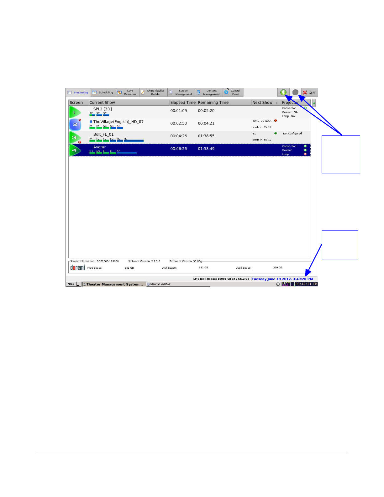
• The Doremi TMS GUI will appear showing the Monitoring tab as presented below (Figure 1):
Backward
and
Forward
Buttons
Date and
Disk
Space
Figure 1: TMS GUI - Monitoring Tab
• The TMS GUI is composed of a set of tabs that allow access to all available functions of the
TMS. The tabs are listed below:
◦ Monitoring
◦ Scheduling
◦ KDM Overview
◦ Show Playlist Builder
◦ Screen Management
◦ Content Management
◦ Control Panel
• The two buttons on the top right corner with left and right arrow icons are backward and
forward functions. They allow the user to go back to the recently viewed tab (Figure 1).
• The bottom of the frame will display the complete date at the right corner and the total disk
space and available free space of the LMS. The font color will change to indicate the available
free space. A yellow color represents 10-20% and red color represents below 10% of total
available free disk space (Figure 1).
TMS.OM.000177.DRM Page 12 of 106 Version 1.4
Doremi Labs
Page 13
4 Quick Start Guide
This quick start guide provides guidance on how to use the TMS GUI in order to configure screens,
create and schedule SPLs, check associated KDM availability, and manage the associated content
ingest processes.
4.1 IP Setup
Follow the procedure below:
The Networking Configuration feature allows the user to set the network parameters. To access the
Networking Configuration feature, go to Menu → LMS Control Panel → Networking Configuration.
In the Devices tab of the window that appears, double click on the Ethernet port that you wish to
configure. Fill out the fields on the window that appears with the help of your IT administrator.
4.2 Logging In
Follow the procedure below:
To be able to configure screens, the user needs to be logged in as admin.
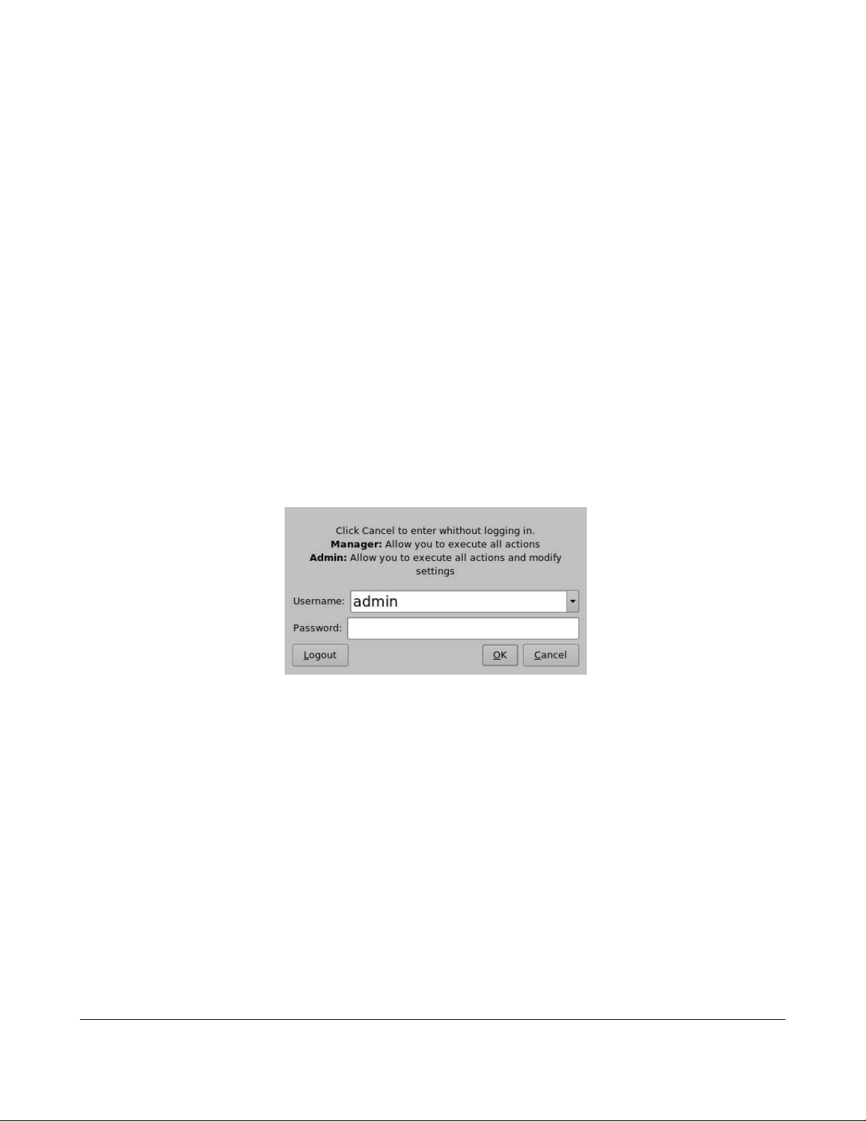
• On the TMS window, go to the Control Panel tab.
• Double-click on the User icon.
• The following window will appear (Figure 2):
Figure 2: Authentication Window
• Select admin in the User name field.
• Enter the appropriate admin password in the password field.
• Click on OK.
• The user is now logged in as admin.
TMS.OM.000177.DRM Page 13 of 106 Version 1.4
Doremi Labs
Page 14
4.3 Screen Setting
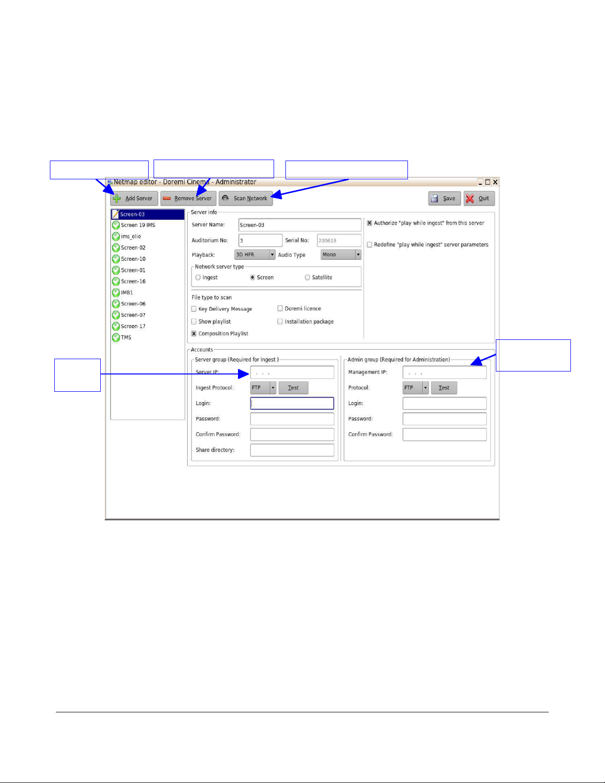
Remove Server Button
Add Server Button
Scan Network Button
Follow the procedure below:
• To perform the set up of the screens, click on the Servers icon in the Control Panel tab.
• The Server Edit screen will appear allowing the user to configure the screens ( Figure 3).
Server
IP
Management
IP
• To add a server, click on the Add Server button.
• To remove a server, select it and click on the Remove Server button.
TMS.OM.000177.DRM Page 14 of 106 Version 1.4
Figure 3: Add Server GUI
Doremi Labs
Page 15
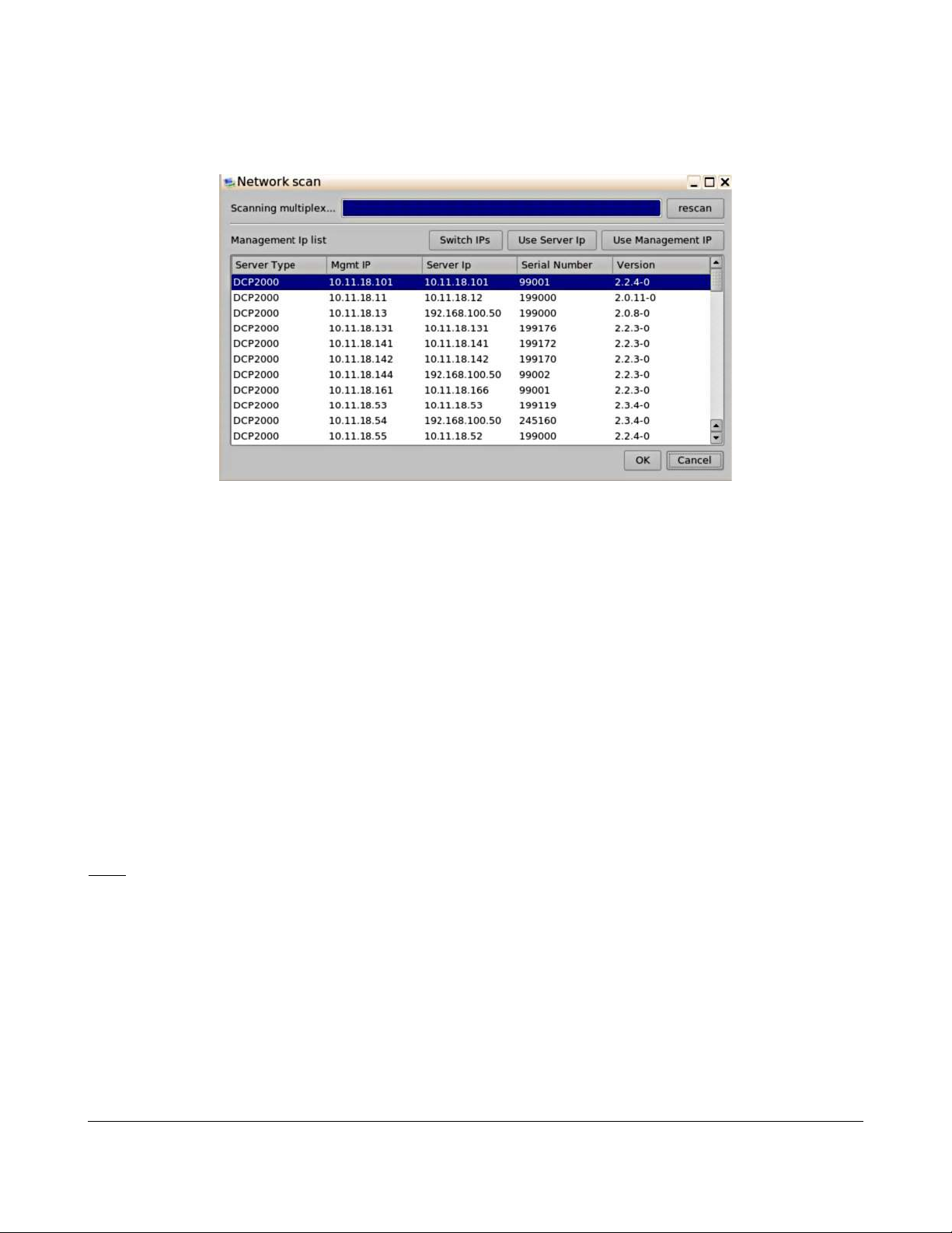
• To scan for available servers, click on the Scan Network button.
◦ The Network Scan window will appear.
◦ Select one or more servers to add and then Click OK to add.
Figure 4: Scan Network Window
• To manually add a server:
◦ Click on the Add Server button.
◦ Fill in the required information ( Figure 3).
▪ For screen servers, enter the auditorium number, usually between 1 and 32, and
specify the type of playback (3D or 2D).
▪ The serial number field will be filled automatically once the Save button is clicked.
▪ Select the network server type and the file type.
• Ingest server should only be selected for the LMS.
▪ Input the server IP and the management IP, with their respective usernames and
passwords. See Figure 3.
▪ The server IP would typically use the “manager” login type and the management IP
would typically use the “admin” login type.
Note: If the LMS Library resides on the TMS server itself, then the IP addresses are the same as the
TMS. The manager and admin account information has to match the account information on that
particular screen server.
• Click on the Save button.
• Click on the Yes button to confirm.
• The servers is now added.
TMS.OM.000177.DRM Page 15 of 106 Version 1.4
Doremi Labs
Page 16

4.4 SPL Creation
Follow the procedure below:
Note: If Show Playlists are complete, then skip this section and proceed to Section 4.5.
• Creating a Show Playlist to be ingested on the screen:
◦ Go to the Show Playlist Builder tab.
◦ Click on the New button followed by the Playlists button.
◦ On the left part of the window, select the composition (CPL) items to add to the playlist.
◦ Select consecutive CPLs by using the shift key or use the "Ctrl" button to select multiple
non-consecutive CPLs.
◦ Click on the Add to Show Playlist button to add all the selected CPLs to the SPL panel.
◦ The available content will appear.
Note: If no composition is visible on the left part of the tab, click the Refresh button ( ).
◦ The two arrow buttons allow the user to change the order of the CPLs in the Show Playlist
panel. Refer to Section 6.4 for SPL creation details.
• To add an automation cue to a CPL present in the Show Playlist:
◦ Select the desired CPL on the right part of the Show Playlist Builder window.
◦ Select the desired trigger cue on the left part of the window.
Note: Click on the drop down menu and select trigger cues to only display trigger cues.
◦ Click the Add to Show Playlist button.
◦ The user will be asked to define Automation Cue parameters. See Section 6.4.3.2.2 for
detailed information.
Note: Trigger Cues can be added to the Show Playlist. Refer to Section 6.4.3.2.3 for the related
procedure.
◦ If there is any content you wish to prevent from being deleted, click on the Edit Locking
button, check the desired content, and click Save.
◦ Click on the Save button to Save the Show Playlist.
◦ The Save window will be prompted.
▪ Assign a name to the ShowPlaylist.
▪ Click on the Save button.
TMS.OM.000177.DRM Page 16 of 106 Version 1.4
Doremi Labs
Page 17
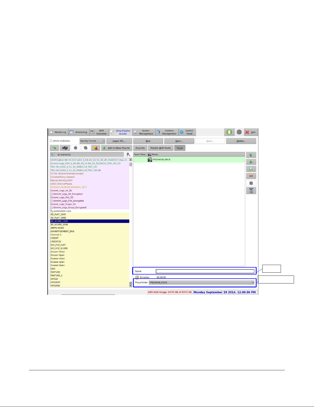
4.4.1 Creating a Show Playlist Pack:
Follow the procedure below:
• The TMS also allows the creation of re-usable playlist packs. Click on the New button in the
show playlist builder; this will bring a pop-up menu with the option: New Playlist Pack.
◦ Click on the Packs button.
▪ Select Pack from the list.
◦ Enter a pack name or select among the pre-defined playlist packs (PRESHOW_PACK,
TRAILER_PACK, FEATURE_PACK, or POSTSHOW_PACK, Figure 5) from the
placeholder list.
Name
Placeholder
Figure 5: SPL Pack
◦ An item representing the name of the pack will be added and highlighted in green (Figure
6).
TMS.OM.000177.DRM Page 17 of 106 Version 1.4
Doremi Labs
Page 18
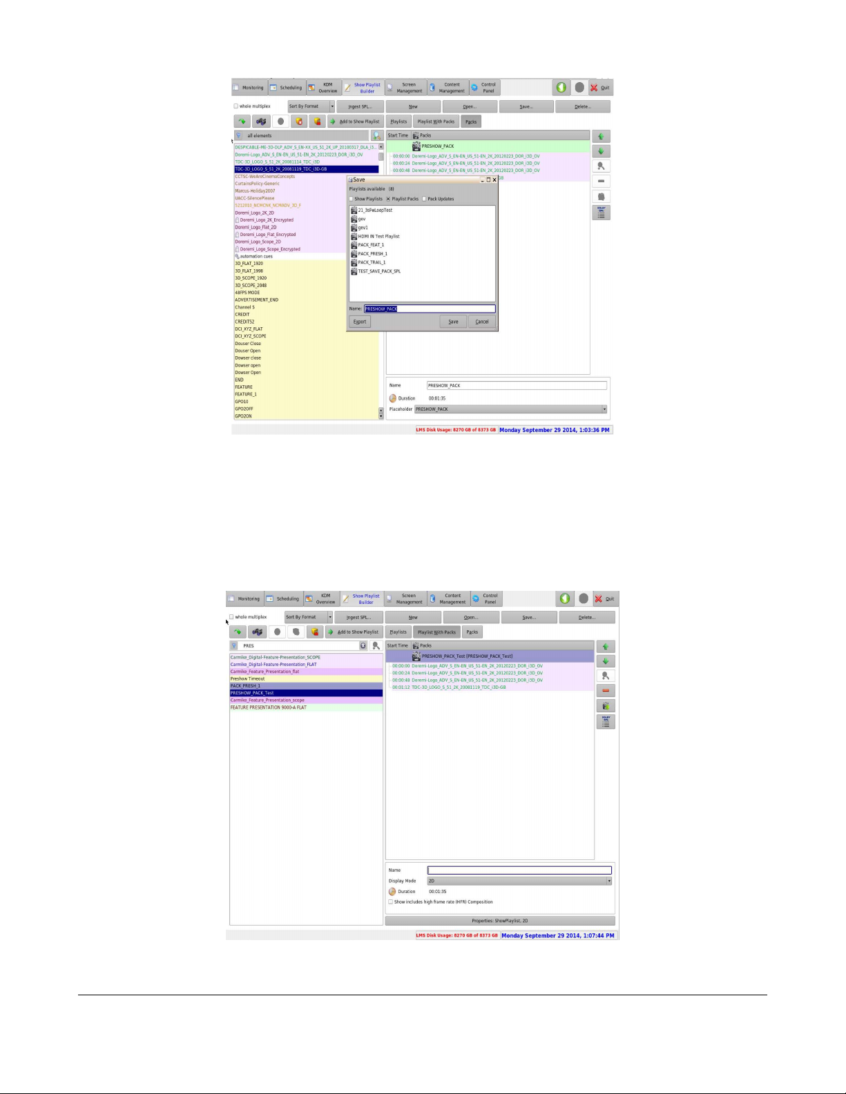
Figure 6: SPL Pack Added
◦ Proceed by adding CPLs, automation cues and trigger cues.
◦ Click on the Save button to save the created pack.
◦ Confirm the name on the Save window.
◦ Click on the Save button to complete saving the created pack.
◦ Once saved, the SPL pack will show, in purple, in the left panel, under Playlist Packs. The
playlist packs can then be added to another SPL like any other CPL or cue item (Figure 7).
Figure 7: SPL Packs Added
TMS.OM.000177.DRM Page 18 of 106 Version 1.4
Doremi Labs
Page 19
4.5 SPL Scheduling
Date of Schedule
Time of Schedule
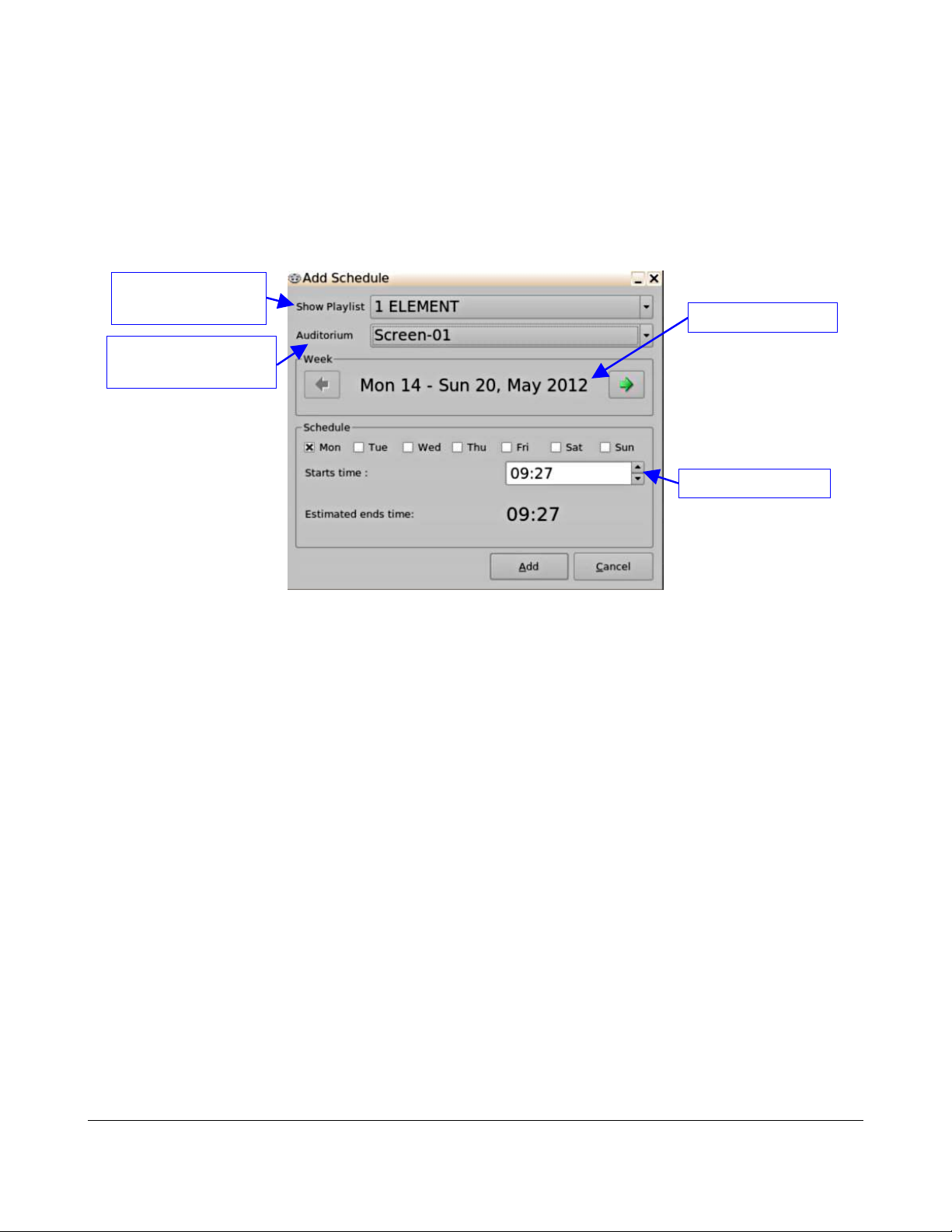
To schedule a Show Playlist playback, follow the steps below:
• Go to the Scheduling tab. See Section 6.2 for additional guidance about this tab.
• Click on the Add Schedule button.
• The following window will appear (Figure 8):
Show Playlist list-
box
Screen Number list-
box
Figure 8: Add Schedule Window
• Select the Show Playlist that needs to be scheduled within the Show Playlist box.
• Choose the Screen Number and the date/time that is to be scheduled.
• Click on the Add button when finished.
• The new schedule will appear on the main window of the Scheduling tab.
• If the SPL is not on the SMS, then the TMS will initiate the SPL transfer to the SMS.
TMS.OM.000177.DRM Page 19 of 106 Version 1.4
Doremi Labs
Page 20

4.6 Uploading KDMs
A Show Playlist might contain encrypted CPLs. To identify an encrypted CPL, look for the lock icon to
the left of its name in the Show Playlist builder window ( ). Each encrypted CPL requires a valid
KDM. If this is the case, make sure that a valid KDM exists for each encrypted CPL in order to be able
to perform the playback.
• Go to the KDM Overview tab. See Section 6.3 for additional guidance on this tab.
• Check in the displayed list of available KDMs to see if there is one for each encrypted CPL in
the Show Playlist.
• If a KDM is missing, click on the KDM Upload button in order to upload it and then follow the
steps.
• Use the Browse button to select the proper KDM folder and upload the KDM (Figure 44).
4.7 Content Management
The Content Management tab will display the status of all ingest jobs. It will show the progress of the
current jobs and it will list all pending jobs. The TMS can execute transfers to four screens
simultaneously. The Content Management tab will allow users to cancel a CPL or SPL transfer.
TMS.OM.000177.DRM Page 20 of 106 Version 1.4
Doremi Labs
Page 21
5 Macro Editor
Button
Button
Upload
Button
A Macro Automation Cue consists of two parts, an Automation Cue and a Trigger Cue. Trigger Cues
are explained fully in Section “Trigger” below. A Trigger Cue is an action that is sent to the screen,
whereas an Automation Cue is sent from a screen. Also, Macro Cues are a sequence of actions,
whereas an Automation Cue is only one action.
5.1 Macro Editor – Macros Tab
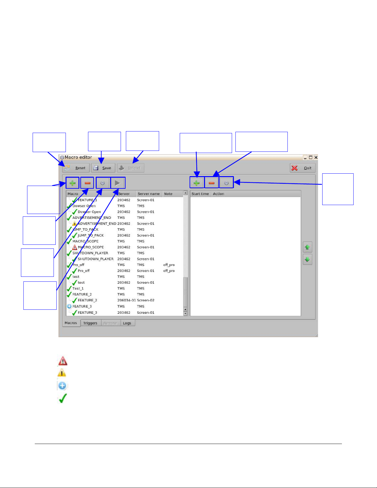
5.1.1 Macros Tab Overview
Reset
Add a
Macro
Button
Delete a
Macro
Button
Edit a
Macro
Button
Execute
a Macro
Button
Save
Add an Action
Button
Delete an
Action Button
Edit an
Action
Button
Figure 9: Macro Editor Window
• : Macro contains missing / wrong configuration.
• : Macro present on the TMS server but has different actions on the screen.
• : Macro is present on the screen, but is not present on the TMS server.
• : Macro is configured properly and has the same definition.
TMS.OM.000177.DRM Page 21 of 106 Version 1.4
Doremi Labs
Page 22

5.1.2 Creating a New Macro
To create a new Macro, follow the procedure below:
• Launch the Macro Editor application.
◦ Menu → Doremi Apps → Macro Editor
• Click on the Add button (Figure 9).
• Input the desired name for the Macro and add comments if necessary.
• After the Macro has been created, click on the Save button to save the created Macro.
• To upload the the Macros to the screens available on the TMS:
◦ Click on the Upload button (Figure 9).
◦ The Macros will be uploaded to the screens.
5.1.3 Editing a Macro
Follow the procedure below to edit a selected Macro:
• Use the arrow keys on the side of the window to scroll through the list of Macros.
• To reset all modifications done locally:
◦ Click on the Reset button (Figure 9).
◦ The Question Window will be prompted.
◦ Click on the Yes button to reset the modifications.
• To edit a selected Macro:
◦ Click on the desired Macro to highlight it.
◦ Click on the settings button or double click on the Macro itself (Figure 9).
◦ The Macro Settings window will be prompted allowing the user to change the name of the
macro or add any additional comments.
◦ On the Macro Settings window, the user can choose to apply the Macro to additional
servers available on the TMS server.
▪ Identify the server by the serial number or by the screen name applied to the server.
▪ Click on the check-box of the desired server to select it.
◦ Click on the OK button to close the Macro Settings window.
◦ Click on the Save button to save the settings applied to the Macro (Figure 9).
• To delete a Macro:
◦ Click on the desired Macro to highlight it.
◦ Click on the Delete button to delete the selected Macro (Figure 9).
◦ Click on the Save button when finished (Figure 9).
TMS.OM.000177.DRM Page 22 of 106 Version 1.4
Doremi Labs
Page 23

• To Execute a Macro:
◦ Click on the desired Macro to highlight it.
◦ Click on the Execute button to execute the selected Macro (Figure 9).
◦ Click on the Save button when finished (Figure 9).
5.1.4 Adding Action(s)
Follow the procedure below:
• To add an action to a Macro:
◦ Click on the desired Macro to highlight it.
◦ Click on the Add an Action button on the right side of the window (Figure 9).
◦ The Add a New Action window will be prompted.
▪ Six action Categories are available:
• Projector
• Input / Output
• Playback
• Macro Control
• Library
• System
• After the Actions have been added, they will need to be uploaded to the screens available on
the TMS:
◦ Click on the Upload button (Figure 9).
◦ The Macros will be uploaded to the screens.
TMS.OM.000177.DRM Page 23 of 106 Version 1.4
Doremi Labs
Page 24
5.1.4.1 Adding a Projector Action
Follow the procedure below:
• Click on the Projector category to highlight it.
• Select from the following action items:
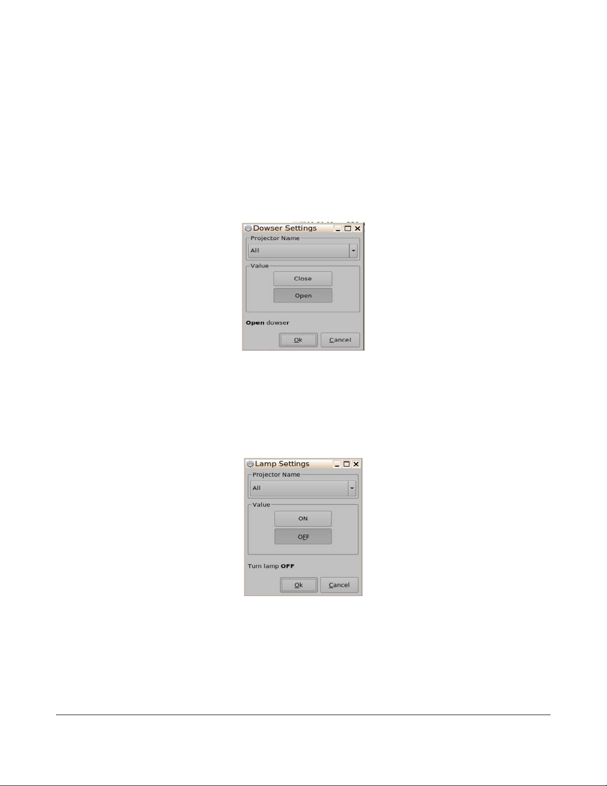
◦ Dowser: Open or Close the selected projector dowser.
▪ Click on the Add button to add this action item to the Macro.
▪ The user can configure the dowser settings on the Dowser Settings window (Figure
10).
Figure 10: Dowser Settings Window
▪ Click on the Ok button when finished to apply the action item to the Macro.
▪ Click on the Save button when finished (Figure 9).
◦ Lamp: Power On or Off the selected projector lamp.
▪ Click on the Add button to add this action item to the Macro.
▪ The user can configure the Lamp settings on the Lamp Settings window (Figure 11).
Figure 11: Lamp Settings Window
• Click on the Ok button when finished to apply the action item to the Macro.
◦ Click on the Save button when finished (Figure 9).
TMS.OM.000177.DRM Page 24 of 106 Version 1.4
Doremi Labs
Page 25
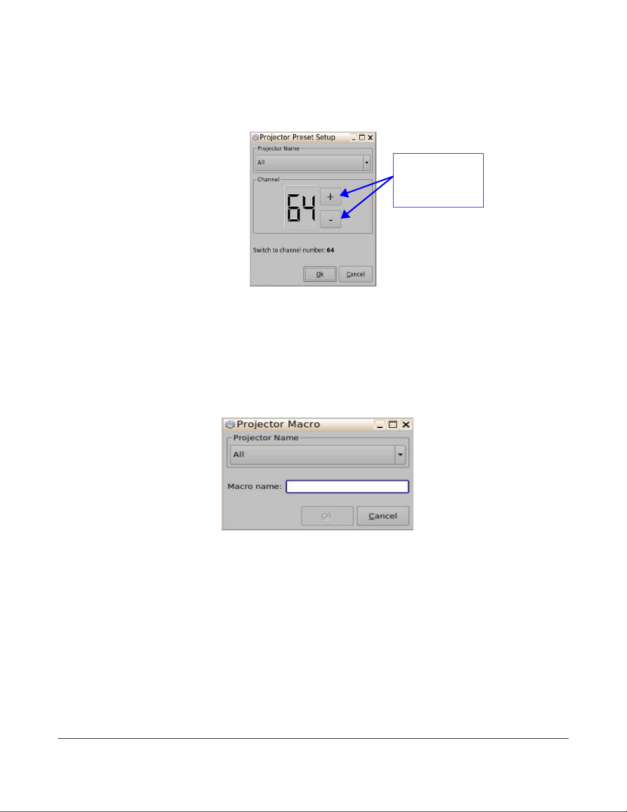
◦ Channel Switch: Switch the selected projector channel
▪ Click on the Add button to add this action item to the Macro.
▪ The user can configure the Channel Switch Settings on the Projector Preset Setup
window (Figure 12).
Use the minus/plus
buttons to change
the value of the
pulse
Figure 12: Projector Preset Setup Window
▪ Click on the Ok button when finished to apply the action item to the Macro.
▪ Click on the Save button when finished (Figure 9).
◦ Macro: Execute a macro defined in the selected projector.
▪ Click on the Add button to add this action item to the Macro.
▪ The user can configure the Macro Settings on the Projector Macro window (Figure 13).
Figure 13: Projector Macro Window
▪ Click on the Ok button when finished to apply the action item to the Macro.
▪ Click on the Save button when finished (Figure 9).
5.1.4.2 Adding an Input / Output Action
Follow the procedure below:
• Click on the Input / Output category to highlight it.
• Select from the following action items:
TMS.OM.000177.DRM Page 25 of 106 Version 1.4
Doremi Labs
Page 26
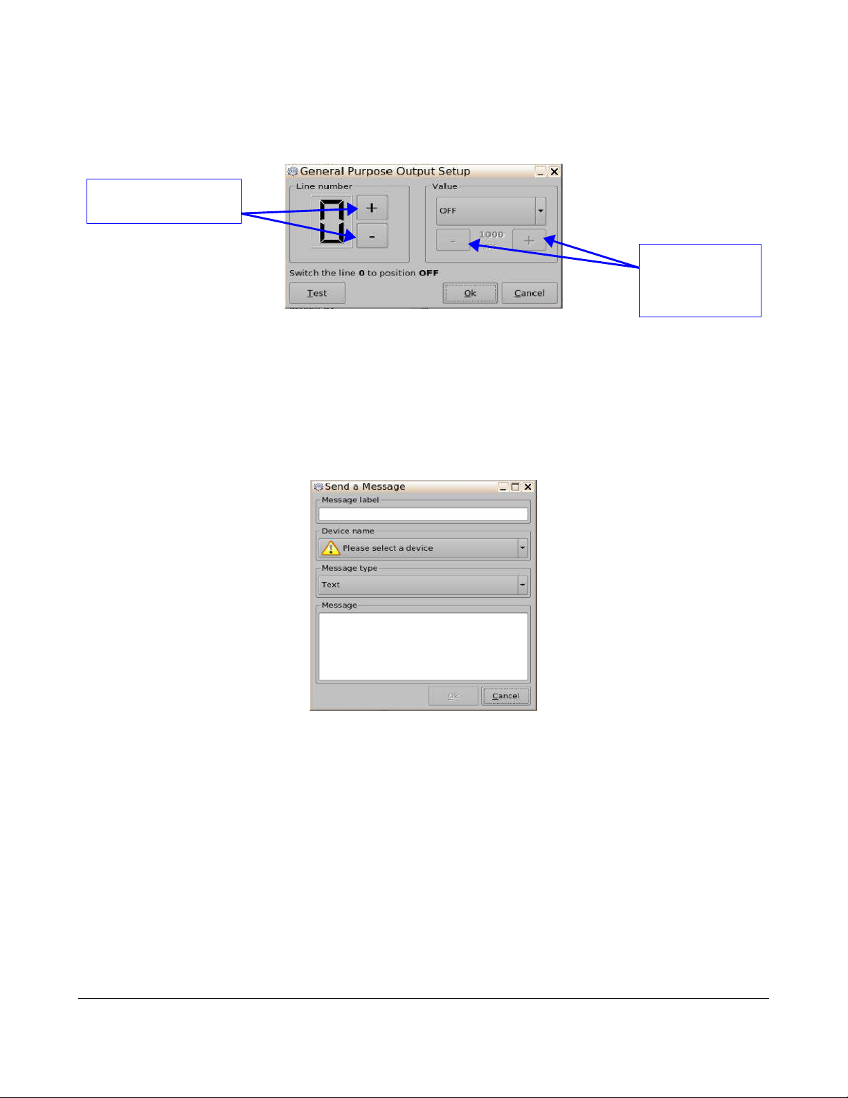
◦ General Purpose Output: Configure a General Purpose Output (GPO) line.
▪ Click on the Add button to add this action item to the Macro.
▪ The user can configure the GPO on the GPO Setup window (Figure 14).
Button used to choose the
GPO line number
Figure 14: GPO Setup Window
▪ Click on the Ok button when finished to apply the action item to the Macro.
▪ Click on the Save button when finished (Figure 9).
◦ Send Message: Send a message to a connected device.
▪ Click on the Add button to add this action item to the Macro.
▪ The user can configure the GPO on the GPO Setup window (Figure 15).
Use the minus/plus
buttons to change
the value of the
pulse
Figure 15: Send a Message Window
▪ Click on the Ok button when finished to apply the action item to the Macro.
▪ Click on the Save button when finished (Figure 9).
TMS.OM.000177.DRM Page 26 of 106 Version 1.4
Doremi Labs
Page 27
5.1.4.3 Adding a Playback Action
Follow the procedure below:
• Click on the Playback category to highlight it.
• Select from the following action items:
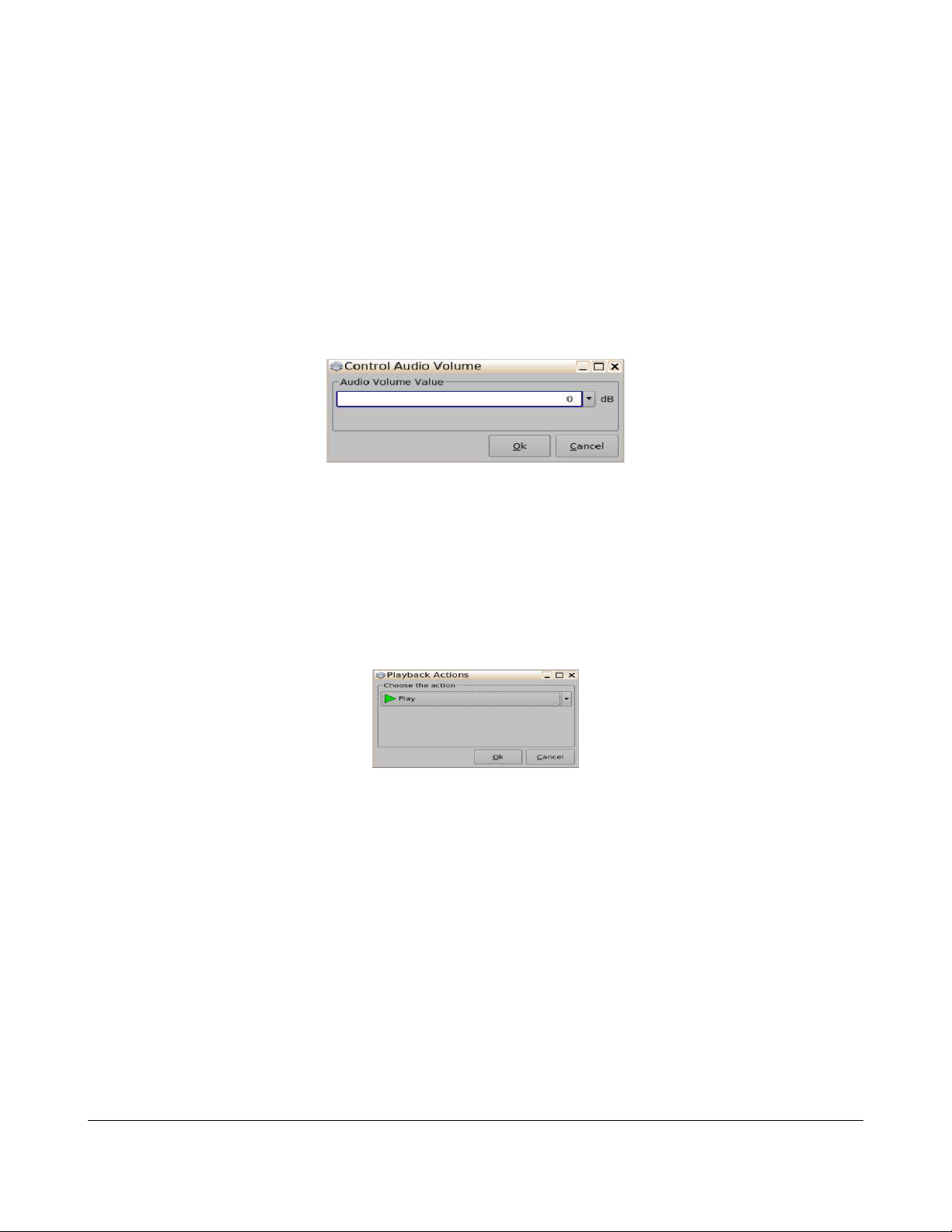
◦ Audio Volume: Control the audio volume output.
▪ Click on the Add button to add this action item to the Macro.
▪ The user can configure the audio volume on the Control Audio Volume window (Figure
16).
Figure 16: Control Audio Volume Window
▪ Click on the Ok button when finished to apply the action item to the Macro.
▪ Click on the Save button when finished (Figure 9).
◦ Playback Actions: Change the playback state.
▪ Click on the Add button to add this action item to the Macro.
▪ The user can configure the playback actions on the Playback Actions window (Figure
17).
Figure 17: Playback Actions Window
▪ Click on the Ok button when finished to apply the action item to the Macro.
▪ Click on the Save button when finished (Figure 9).
TMS.OM.000177.DRM Page 27 of 106 Version 1.4
Doremi Labs
Page 28

◦ Video Output Actions: Change the default video output format.
▪ Click on the Add button to add this action item to the Macro.
▪ The user can configure the video output actions on the Video Output Actions window
(Figure 18).
Figure 18: Video Output Actions Window
▪ Click on the Ok button when finished to apply the action item to the Macro.
▪ Click on the Save button when finished (Figure 9).
◦ Sensio3D: enable or Disable the Sensio3D output format.
▪ Click on the Add button to add this action item to the Macro.
▪ The user can configure the Sensio3D settings on the Sensio3D window (Figure 19).
Figure 19: Sensio3D Window
▪ Click on the Ok button when finished to apply the action item to the Macro.
▪ Click on the Save button when finished (Figure 9).
TMS.OM.000177.DRM Page 28 of 106 Version 1.4
Doremi Labs
Page 29
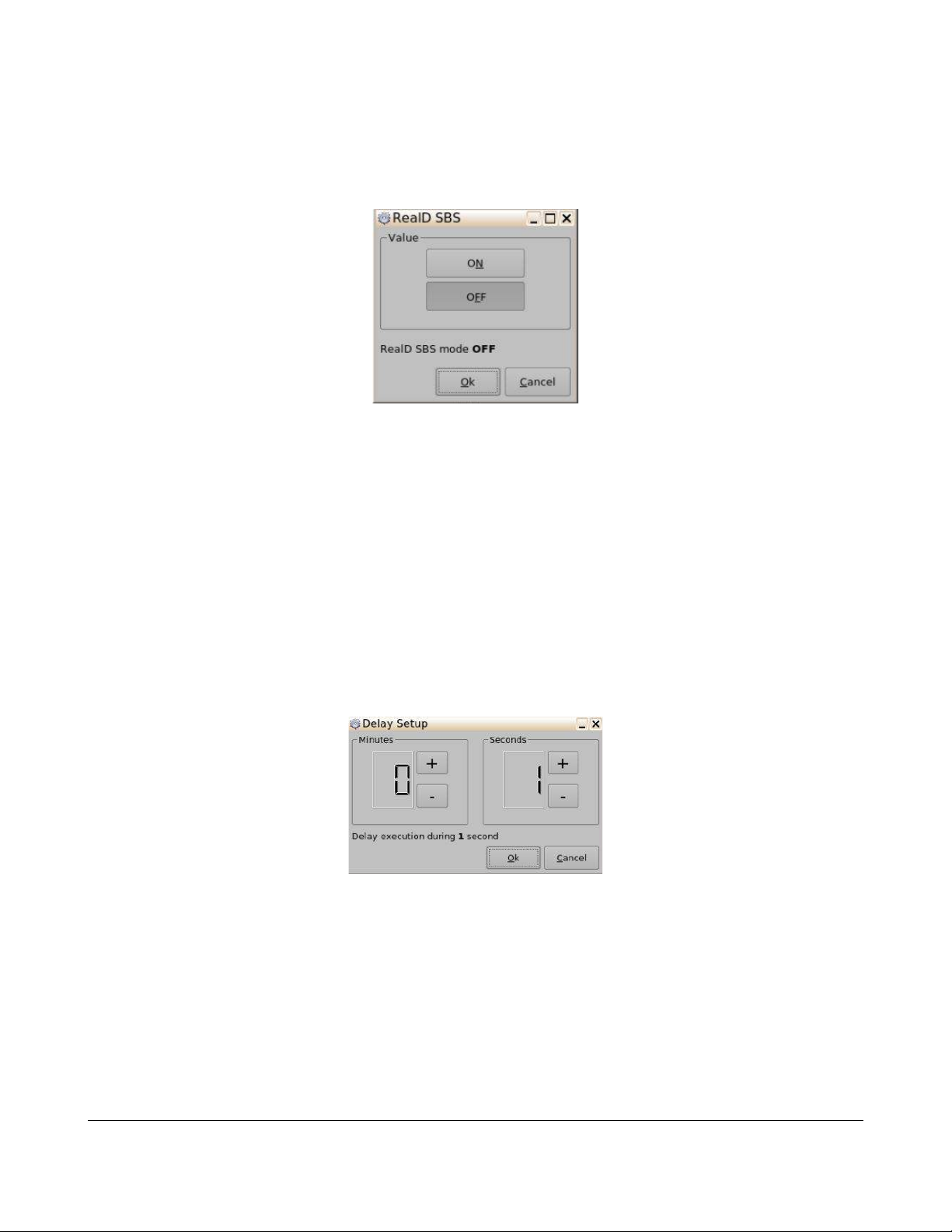
◦ RealD SBS: Enable or Disable RealD SBS output format.
▪ Click on the Add button to add this action item to the Macro.
▪ The user can configure the RealD SBS settings on the RealD SBS window (Figure 20).
Figure 20: RealD SBS Window
▪ Click on the Ok button when finished to apply the action item to the Macro.
▪ Click on the Save button when finished (Figure 9).
5.1.4.4 Adding a Macro Control Action
Follow the procedure below:
• Click on the Macro Control category to highlight it.
• Select from the following action items:
◦ Delay: Insert a delay between actions.
▪ Click on the Add button to add this action item to the Macro.
▪ The user can configure the Delay settings on the Delay Setup window (Figure 21).
Figure 21: Delay Setup Window
▪ Click on the Ok button when finished to apply the action item to the Macro.
▪ Click on the Save button when finished (Figure 9).
◦ Purge Pending Macro: Purge the current macro execution stack.
▪ Click on the Add button to add this action item to the Macro.
▪ Click on the Save button when finished (Figure 9).
TMS.OM.000177.DRM Page 29 of 106 Version 1.4
Doremi Labs
Page 30
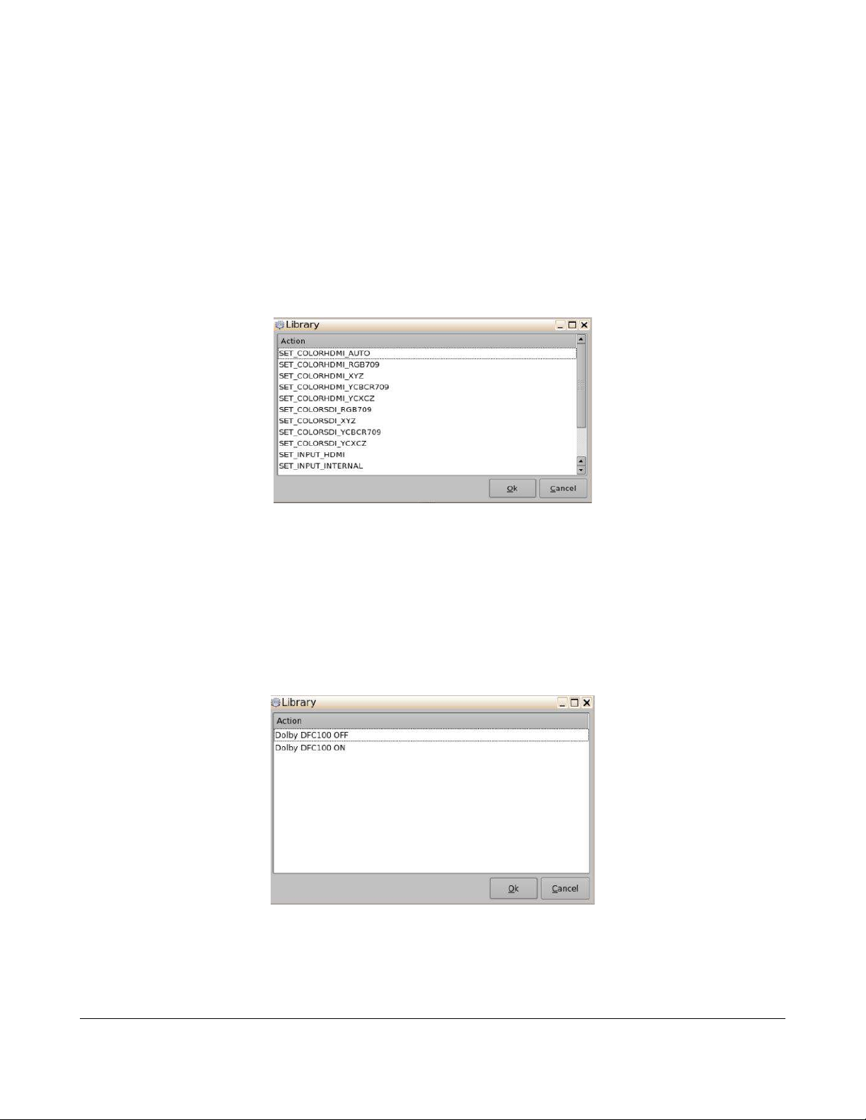
5.1.4.5 Adding Action from the Library
Follow the procedure below:
• Click on the Library category to highlight it.
• Select from the following action items:
◦ Certainty: Manage Certainty products.
▪ Click on the Add button to add this action item to the Macro.
▪ The user can select the actions to manage Certainty products on the Library window
(Figure 22).
Figure 22: Library Action Window - Certainty
▪ Click on the Ok button when finished to apply the action item to the Macro.
▪ Click on the Save button when finished (Figure 9).
◦ Dolby DFC100: Manage Dolby DFC100 product.
▪ Click on the Add button to add this action item to the Macro.
▪ The user can select the actions to manage Dolby products on the Library window
(Figure 23).
Figure 23: Library Action Window – Dolby DFC100
▪ Click on the Ok button when finished to apply the action item to the Macro.
▪ Click on the Save button when finished (Figure 9).
TMS.OM.000177.DRM Page 30 of 106 Version 1.4
Doremi Labs
Page 31

◦ eCNA: Manage eCNA products.
▪ Click on the Add button to add this action item to the Macro.
▪ The user can select the actions to manage eCNA products on the Library window
(Figure 24).
Figure 24: Library Action Window – eCNA
▪ Click on the Ok button when finished to apply the action item to the Macro.
▪ Click on the Save button when finished (Figure 9).
◦ Jnior exapansion module: Manage Jnior with the expansion module products.
▪ Click on the Add button to add this action item to the Macro.
▪ The user can select the actions to manage Jnior with expansion module products on
the Library window (Figure 25).
Figure 25: Library Action Window – Jnior w/Expansion Modules
▪ Click on the Ok button when finished to apply the action item to the Macro.
▪ Click on the Save button when finished (Figure 9).
TMS.OM.000177.DRM Page 31 of 106 Version 1.4
Doremi Labs
Page 32

◦ Jnior: Manage Jnior products.
▪ Click on the Add button to add this action item to the Macro.
▪ The user can select the actions to manage Jnior products on the Library window
(Figure 26).
Figure 26: Library Action Window – Jnior w/Expansion Modules
▪ Click on the Ok button when finished to apply the action item to the Macro.
▪ Click on the Save button when finished (Figure 9).
5.1.4.6 Adding a System Action
Follow the procedure below:
• Click on the System category to highlight it.
• Select the following action item:
◦ System Shutdown: Shutdown the player.
▪ Click on the Add button to add this action item to the Macro.
▪ Click on the Save button when finished (Figure 9).
TMS.OM.000177.DRM Page 32 of 106 Version 1.4
Doremi Labs
Page 33

5.2 Macro Editor – Triggers Tab
A “Trigger Cue" allows for the execution of a Macro Automation Cue upon the occurrence of an event
from an external device using a “Signal” or “General Purpose Input.” When you select an event to
occur from the external device, the occurrence of that event “triggers” a Macro Automation Cue. The
Macro Automation Cue will then be executed. Both the event and the Marco Automation Cue are
defined during the “Trigger Cue” creation.
5.2.1 Trigger Tab Overview
Reset
Button
Add a
Trigger
Button
Remove a
Trigger
Button
Edit a
Trigger
Button
Save Button
Upload Button
Add an Action
Button
Remove an
Action Button
Edit an Action
Button
Figure 27: Macro Editor – Trigger Tab Window
TMS.OM.000177.DRM Page 33 of 106 Version 1.4
Doremi Labs
Page 34

5.2.2 Creating a New Trigger
Follow the procedure below:
• Launch the Macro Editor application.
◦ Menu → Doremi Apps → Macro Editor
• Click on the Triggers tab to open the Triggers window.
• Click on the Add a Trigger button (Figure 27).
• Input the name of the trigger and any necessary comments.
• Click on the Ok button to add the trigger to the triggers list.
• To upload the the Triggers to the screens available on the TMS:
◦ Click on the Upload button (Figure 27).
◦ The Triggers will be uploaded to the screens.
5.2.3 Editing a New Trigger
Follow the procedure below:
• Use the arrow keys on the side of the window to scroll through the list of Macros.
• To reset all modifications done locally:
◦ Click on the Reset button (Figure 27).
◦ The Question Window will be prompted.
◦ Click on the Yes button to reset the modifications.
• Click on the desired Trigger to highlight it.
• To edit a selected Trigger:
◦ Click on the settings button or double click on the trigger itself to open the Trigger Settings
window (Figure 27).
Figure 28: Trigger Settings Window
Note: Servers can be added after an action has been assigned to a trigger.
TMS.OM.000177.DRM Page 34 of 106 Version 1.4
Doremi Labs
Page 35

◦ The Trigger Settings window will be prompted allowing the user to change the name of the
trigger or add any additional comments.
◦ Click on the OK button to close the Macro Settings window.
◦ Click on the Save button to save the settings applied to the Macro (Figure 27).
• To delete a Trigger:
◦ Click on the desired Trigger to highlight it.
◦ Click on the Delete button to delete the selected Trigger (Figure 27).
◦ Click on the Save button when finished (Figure 27).
5.2.4 Adding an Action to a Trigger
Follow the procedure below to add an action to a selected trigger:
• To add a new action to a trigger:
◦ Click on the desired trigger on the left side of the Macro Editor window.
◦ Click on the Add an Action button to add an action to the selected trigger (Figure 27).
◦ The Events window will be prompted (Figure 29).
Figure 29: Events Window
◦ The following actions are available for Triggers:
▪ General Purpose Input (GPI) - Configure a General Purpose Input (GPI) line.
• To add a GPI:
◦ Click on the General Purpose Input button.
◦ The General Purpose Input Setup window will be prompted (Figure 30).
Button used to choose the
GPI line number
Figure 30: General Purpose Input Setup Window
TMS.OM.000177.DRM Page 35 of 106 Version 1.4
Doremi Labs
Page 36

◦ Define the line number and value click the Ok button.
◦ Click on the Save button to save the configuration (Figure 27).
▪ Signal – Configure the settings for the external device(s) being used.
• To add a Signal:
◦ Click on the Signal button.
◦ The Signal Setup window will be prompted (Figure 31).
Signal Library
Button
Figure 31: Signal Setup Window
◦ Click on the Signal Library button available in the Source device name section.
◦ Select the desired device.
◦ Click on the menu button.
◦ The Signal Library window will be prompted.
◦ Select the same device selected in the Source device name field.
◦ Select the desired signal.
◦ Click on the Ok button to close the Signal Library window.
◦ Click on the Ok button on the Signal Setup window.
◦ Click on the Save button to save the configuration (Figure 27).
TMS.OM.000177.DRM Page 36 of 106 Version 1.4
Doremi Labs
Page 37

5.3 Macro Editor – Remote Tab
The TMS macro editor will detect if meanwhile the TMS user is editing the macros something has
changed on one or several screens and will show the popup SEE FIGURE. If user clicks cancel, the
Remote Tab will be enabled and will show what has changed remotely on screen(s) and will give the
option to update the TMS macros.xml or ignore the screens remote changes.
• The Question window will be prompted.
◦ Click on the Yes button to override the remote changes.
◦ Click on the Cancel button to view the changes on the Remote Tab.
• Ont the Remote Tab:
◦ Click on the desired Screen.
Note: The user can identify the screen by viewing the serial number or server name.
• Use the arrow keys on the side of the window to scroll through the list of Macros.
• The Macro which was modified on the screen can be identified by caution image ( ). See
Figure 32
Reset
Button
Caution
Image
Figure 32: Macro Editor Window – Remote Tab
• Click on the modified Macro.
◦ The Update Local and Ignore buttons will be enabled.
▪ Update Local Button: Update TMS macros.xml (Figure 33).
▪ Ignore Button: Ignore the screens remote changes (Figure 33).
TMS.OM.000177.DRM Page 37 of 106 Version 1.4
Doremi Labs
Page 38

Update
Button
Button
Local
Button
Ignore
Figure 33: Macro Editor Window – Remote Tab – Macro Selected
• To reload all Macros:
◦ Click on the Reset button (Figure 32).
◦ The Macros will reload to the screens available on the TMS server.
5.4 Macro Editor – Logs Tab
The Logs tab will log keep track of the actions the user executes on the TMS server.
Clear
Figure 34: Macro Editor Window – Logs Tab
• To clear logs
◦ Click on the Clear button (Figure 34).
◦ The logs will be cleared.
TMS.OM.000177.DRM Page 38 of 106 Version 1.4
Doremi Labs
Page 39

5.5 Logout
To prevent unauthorized changes to settings and scheduling, click logout.
• Go to the Control Panel tab and click on the User icon.
• The following window will appear (Figure 35):
Logout Button
Figure 35: Authentication Window
• Click on Logout.
TMS.OM.000177.DRM Page 39 of 106 Version 1.4
Doremi Labs
Page 40

6 TMS GUI Tabs Description
6.1 Monitoring Tab
• To enter the Monitoring tab, click on Monitoring on the top of the GUI.
• The Monitoring window is composed of two different parts (Figure 36):
1. The top part lists all the screens added to the TMS together with their states: offline,
online, and playing.
2. The bottom part displays information about the selected screens.
6.1.1 Presentation
Screens are listed vertically under the screen column header. Each screen is identified with an icon
displaying the screen number inside it. The icon's color and shape reflects the current status of the
SMS. Below are the different icons used:
• :Blue square indicates online and idle status.
• :Green triangle indicates online and playing content.
• :Red hexagon indicates offline.
• :Orange square indicates that the media block is disconnected.
• A smaller icon can appear next to the screen number when the available free space drops
below a certain threshold.
◦ :A warning icon in yellow indicates that the configured warning threshold (11% - 20%)
for the remaining free space was reached.
◦ :A critical icon in red indicates that the configured critical threshold (10% or less) for the
remaining free space was reached.
◦ : Playback is configured as Manual Playback.
◦ : Connection error between TMS and server.
TMS.OM.000177.DRM Page 40 of 106 Version 1.4
Doremi Labs
Page 41

Monitoring
Tab
Arrow
Icon
Screen
Icons
SPL
Name
Clip Bar
Content
Type
Screen
Information
Figure 36: TMS GUI - Monitoring Tab
Note: The small warning/critical icon can be used to display some other warnings. Point the mouse
over the screen icon to display the description of the errors or warnings.
To the right of the screen icon, the following information is displayed only when the screen is in
playback mode.
1. A Show Playlist name is displayed in conjunction with one or more bars beneath. The bars
represent the different clips in the SPL. The short bar is for trailers and the long bar is for
features.
◦ Hovering over the name will list the content in each SPL.
◦ The letters above the bars indicate what type of content the clip contains:
▪ FL= Flat
▪ SC= Scope
▪ HD= High Definition
▪ FU= Full
▪ PA= Pattern
2. Elapsed time.
3. Remaining time.
4. Next Show.
5. Projector.
• The last two columns can appear and disappear by clicking on the Arrow icon.
• To access the Screen Management tab associated with the selected screen, double-click on
the screen icon and the GUI will display the Screen Management tab (Section 6.5).
TMS.OM.000177.DRM Page 41 of 106 Version 1.4
Doremi Labs
Page 42

• Using the mouse to hover over the SPL name or the clip bars will list the content found in the
SPL.
6.1.2 Screen Information
The bottom part will display information specific to the server on a particular screen (Figure 36). By
selecting a screen on the top, the following information will be displayed:
1) Server Serial Number.
2) Software and Firmware version.
3) Total disk space; used and free. The color of the free space will change if it drops below a
certain threshold. The color yellow indicates a free space between 10% and 20%. The color
red indicates free space below 10% of total disk space.
6.2 Scheduling Tab
6.2.1 Standard Use
• To enter the Scheduling tab, click on Scheduling on the top of the GUI at any time during the
TMS GUI usage.
• The Scheduling tab is illustrated below (Figure 37):
Date
Selection
Previous
and Next
Button
Refresh
Button
Delete All
Schedules
Delete
Schedule
Edit Links Button
Swap Schedules Button Copy Schedules Button
View
Field
Past
Schedule
Entry
Scheduling
Window
Schedule
Figure 37: TMS GUI - Scheduling Tab
TMS.OM.000177.DRM Page 42 of 106 Version 1.4
Doremi Labs
Add
Page 43

• Edit Links button: This will link a specific movie name to an SPL.
• Swap Schedules Button: Allows the user to swap schedules between screens.
• Copy Schedules Button: Allows the user to copy schedules between screens and on specific
dates.
• Previous Day and Next Day button: These buttons will show the schedule by the selected view
period. It can be daily, weekly, monthly, or yearly.
• Date Selection field: This will allow the user to specify the starting day of the schedule.
• Refresh button: This will refresh the scheduling window.
• View field drop-down menu: This will specify the period to display in the scheduling window
starting with the day specified in the date selection.
• Delete Schedule button: This will delete the selected entry from the schedule. The selected
entry will be deleted immediately without confirmation.
• Delete All Schedules button: This will delete the entire schedule on both the TMS and the
screens associated with the system. A confirmation is required in order for the operation to be
completed. Only a manager login can execute this operation. The operation will delete the
schedule only; no content will be lost in the process.
• Add Schedule button: This will allow the user to manually schedule an SPL on a specific
screen at a specific time and day.
• The Scheduling window will list all the entries starting from the date in the Date Selection up to
the period selected in the View drop-down menu.
• Schedules that have already passed will be shown with the line highlighted in gray.
6.2.1.1 Entry Description
• Each entry takes one line and is composed of four fields as listed below:
◦ Type
◦ Date and Time
◦ Screen Name
◦ Movie Name
◦ Notes
• The font color will reflect the status of the entry.
◦ Black font: Ready
◦ Red font: Indicates an error
◦ A gray font: Represents past entries
• The error type will be reflected in the notes.
TMS.OM.000177.DRM Page 43 of 106 Version 1.4
Doremi Labs
Page 44

6.2.2 Manager/Administrator Use
Show Playlists
Window
All Button
Link Button
If the user is logged in as either manager or admin, they will be able to modify the settings. In this tab,
it corresponds to:
• A schedule addition
• Schedule(s) deletion
• Links editing
To add a schedule, click on Add Schedule:
• The following window will appear (Figure 38):
Figure 38: Add Schedule Window
• To schedule a playback of a Show Playlist for a given auditorium and time, click on Add when
finished.
• The new schedule will appear in the schedule list.
• Select the appropriate View mode from the drop-down menu.
To delete an existing schedule, select it in the schedule list and click on Delete Schedule.
• The schedule will disappear.
• To delete all the schedules, click on the Delete All Schedules button.
To link a movie listed in the POS file to a specific Show Playlist, click on the Edit Links button (Figure
39).
Movies
Window
Linked Button
Unlinked Button
TMS.OM.000177.DRM Page 44 of 106 Version 1.4
Figure 39: Edit Links Window – Unlinked View
Doremi Labs
Page 45

• The left side provides the list of movies listed in the POS File. This largely depends on whether
Button
Unlinked POS
Title
or not the Show Playlist is linked with the POS file.
• If the Unlinked button is clicked, the Movies window will display the list of movies that are not
linked to any Show Playlist.
• Select one movie from the POS File and one from the Show Playlist and click on Link.
• The Show Playlist will be linked to the movie title defined in the POS File.
• The playback of the Show Playlist will be performed according to the schedule of the linked
movie title defined in the POS File.
• To view the movie titles already linked to Show Playlists, click on the Linked button on the
bottom of the Edit Links window.
• The following window will be displayed (Figure 40):
Unlink
Figure 40: Edit Links Window – Linked View
• From this window, the user can select one title and unlink it by clicking on the Unlink button.
• To view the whole list of movie titles listed in the POS file, whether they are linked or unlinked,
click on All.
• The Movies window will reflect the whole movie list, indicating the movie titles that are unlinked
in red, as presented below (Figure 41):
TMS.OM.000177.DRM Page 45 of 106 Version 1.4
Figure 41: Edit Links Window – Linked View
Doremi Labs
Page 46

6.3 KDM Overview Tab
Button
Indicates which
screen the KDM
can be used on
Content Title
• To enter the KDM Overview tab, click on KDM Overview Tab on the top of the GUI at any time
during the TMS GUI usage.
• The KDM Overview tab will display all the KDMs available on the network using a color code to
indicate their validity.
• Below are the color codes and their correspondences:
◦ A green line corresponds to a KDM valid for more than 48 hours.
◦ A yellow line corresponds to a KDM valid for less than 48 hours.
◦ A red line corresponds to a KDM that is not currently valid, but will be valid in the future.
◦
KDM Location
Filter Menu
KDM Upload
Composition
Play List-
Delete
Expired KDMs
Button
KDM Overview Tab
Legend
KDM
Search Bar
Send KDM
to Screen
Button
Delete
KDMs
Button
Figure 42: KDM Overview Tab
• The first column indicates on which screen the KDM can be used, and the next columns
indicate the Content Title of the corresponding Composition Playlist. It also indicates the start
and end dates of the KDM validity window (Figure 42).
• The following color significance (Figure 43) is available by clicking the Legend button (Figure
42).
TMS.OM.000177.DRM Page 46 of 106 Version 1.4
Doremi Labs
Page 47

Figure 43: KDM Highlight Window
Upload All
Button
• To delete a KDM, select it in the KDM list and click the Delete KDM button (Figure 42).
• To delete all expired KDMs, click the Delete Expired KDM button (Figure 42).
• To send a KDM from the TMS server to a desired screen, click on the Send KDM to Screen
button
• The KDMs Upload button (Figure 42) allows for ingestion of KDMs from the TMS (USB or local
directory). Use the Browse button to select the folder from which to ingest the KDMs (Figure
44).
Browse
Button
List of
available
KDMs in
the
selected
Upload
Selected
Button
folder
Close
Button
Figure 44: KDM Upload Window
◦ To upload one or more KDMs, select it and click the Upload Selected button.
◦ To upload all KDMs, click the Upload All button.
◦ Click the Close button to close the KDMs Upload window.
• The KDM Location Filter Menu allows the user to view the KDM(s) available in a selected
location.
• The KDM Search Bar allows the user to search for specific KDM(s) in the selected location.
TMS.OM.000177.DRM Page 47 of 106 Version 1.4
Doremi Labs
Page 48

Note: Right clicking on an Uploading of KDM line in the bottom part of the tab will show a menu to
clear the status logs or delete the selected message (Figure 45).
Figure 45: KDMs Upload Window – Right Click Menu
6.4 Show Playlist Builder Tab
6.4.1 Tab Overview
• To enter the Show Playlist Builder tab, click on Show Playlist Builder at any time during the
TMS GUI usage (Figure 46).
• The Show Playlist Builder tab contains:
◦ A left part with all the Digital Cinema Packages (DCP) that were found on the LMS:
features, trailers, and advertisements. They are together with the available automation
cues and trigger cues. The Whole Multiplex feature will show all the available DCPs found
on one or more screens. All content that is shown in bold font exists on the LMS and on
one or more screens. Content with a fine line does not exist on the LMS.
◦ A right part used to display the content of a given Show Playlist, that is already created or
existing. A Show Playlist is described in the next step.
Note: Content type is differentiated by color and font. Pointing to a certain content will make an
informative tool-tip showing the format and location available (Figure 46).
Whole
Multiplex
check-box
Informative
Tool
Figure 46: Show Playlist Builder Tab
TMS.OM.000177.DRM Page 48 of 106 Version 1.4
Doremi Labs
Page 49

6.4.2 Colors
Different colors represent different formats in the Show Playlist Builder:
• Flat:
◦ 2D is dark blue.
◦ 3D is light blue.
• Scope:
◦ 2D is dark green.
◦ 3D is light green.
• HD:
◦ 2D is dark brown.
◦ 3D is light brown/orange.
• Full:
◦ 2D is dark red.
◦ 3D is light red.
6.4.3 Show Playlist Creation
A Show Playlist defines a succession of DCPs and Automation Cues. It provides the events chain to
be taken into account for the playback of a show. A Show Playlist can be newly created or an existing
Show Playlist can be opened and edited.
6.4.3.1 Principle
The Show Playlist Builder tab allows the users to create their own Show Playlist from the elements
listed in the Contents window.
• To add an element to the Show Playlist, select it. The element will be reverse highlighted.
• There are two ways to find content in the tab.
• To search for a specific CPL, click on the Find Content button (Figure 48) and type
in the name of the CPL (Figure 47).
Figure 47: Find Content Window
• To filter the CPLs, click on the Filter button (Figure 48). The user can filter by
advertisements, automation cues, features, patterns, playlist packs, policy, psa,
rating, shorts, teasers, tests, trailers, transnational, trigger cues, and a custom
search.
TMS.OM.000177.DRM Page 49 of 106 Version 1.4
Doremi Labs
Page 50

Button
Find
Drop-down List
Search
Bar
Playlist Button
Content
Button
Filter
Sorting Option
Add to Show
Figure 48: Find Content Options
• There is also a Sorting Option drop-down list that allows the user to sort the content on the
left side of the window by name, format, and locked material (Figure 48). See Section 6.4.5
for more information on locked material.
• The user can also search for a specific item by typing in the name of the item into the
search bar, see Figure 48.
• Click on the Add to Show Playlist button to add the highlighted CPL.
• The element will appear on the right part of the window. Repeating this operation with all the
required elements will lead to a Show Playlist (Figure 49):
TMS.OM.000177.DRM Page 50 of 106 Version 1.4
Doremi Labs
Page 51

Ingest
Button
SPL
Button
Delete
SPL
Properties
Button
Figure 49: Show Playlist Creation
• If the user is trying to add content with different formats, the Dissimilar Content window will
appear asking the user if they would like to continue. Click Add Anyway to add the content to
the SPL regardless of its format.
Figure 50: Dissimilar Content Window
• If an element needs to be deleted from the Show Playlist, select it in the Show Playlist window
and click on the Delete button. See Figure 49.
• The Ingest SPL button (Figure 49) forces the SPL ingest on a selected screen right away. The
SPL ingest window that will appear is presented below (Figure 51):
TMS.OM.000177.DRM Page 51 of 106 Version 1.4
Doremi Labs
Page 52

Start
Ingest
Button
Figure 51: Show Playlist Ingest Window
• Select the SPL to ingest and the destination screen, then click on the Start Ingest button
(Figure 51).
• Clicking on the SPL Properties button (Figure 49) will make the SPL Properties window visible
(Figure 52).
Close
Button
Figure 52: SPL Properties Window
• If necessary, change the name of the SPL and set to 3D SPL or 2D SPL using the Display
Mode list box (Figure 53).
• The default setting is 2D SPL.
TMS.OM.000177.DRM Page 52 of 106 Version 1.4
Doremi Labs
Page 53

Figure 53: SPL Name and Display Mode Settings
• To hide the SPL Properties window, click on the Close button, See Figure 52.
Save
Button
• Click the Save button, located on the top of the tab, to record the SPL settings (Figure 53).
• If it is not saved, the SPL settings will be ignored.
6.4.3.2 Element Types
Different types of elements are available:
• Audio-visual content: Feature, Test Content, Trailer, Rating, and Black.
• Automation cues: Macro Automation cues from generation based on the Macro Editor
application.
• Trigger cues: Based on the generation of the Macro Editor application.
• Packs: Playlist Packs and Pack Updates
6.4.3.2.1 Audio-Visual Content
When audio-visual content is encrypted, a lock icon is displayed at the beginning of its line. It means
that a corresponding KDM will be required to play content (Figure 54):
TMS.OM.000177.DRM Page 53 of 106 Version 1.4
Doremi Labs
Page 54

Lock
Icon
Figure 54: Encrypted Content Tag
6.4.3.2.2 Automation Cues
Macro Automation Cues can be added to an element of the Show Playlist.
• Select the element in the right part of the window.
• Select the desired Automation Cue on the left part of the window.
• Click on the Add to Show Playlist button.
• The user will be asked to define the offset of this Automation Cue from the beginning or the
end of the chosen element using the following window (Figure 55):
Name of the element
Offset indicating the
starting point of the
Macro Automation
Cue within the
element
defined by this Macro
Automation Cue
Arrow buttons to
use to define the
offset
Figure 55: Automation Cue Offset Definition
• Click the OK button when finished.
TMS.OM.000177.DRM Page 54 of 106 Version 1.4
Doremi Labs
Page 55

• The Macro Automation Cue will appear under the element on the right part of the tab (Figure
56):
Automation
Cue Added
Figure 56: Automation Cue Added to an Element
• This operation is repeatable for the same element or for another element of the Show Playlist.
6.4.3.2.3 Trigger Cue
A Trigger Cue allows for the planning of the execution of Macro Automation Cues when the underlying
condition happens.
For example, if a Trigger Cue is based on the condition, “Wait for GPI #1 ON,” the user can link a
specific Macro Automation Cue as presented above in order to execute such Macro when GPI #1 is
asserted.
The user has the choice to program a Trigger Cue to be available during the whole Show Playlist or
only during a specific Show Playlist element.
To define a Trigger Cue for the whole Show Playlist:
• Select a Trigger Cue from the left side of the GUI.
• Click on Add to Show Playlist.
• The following window will appear (Figure 57):
TMS.OM.000177.DRM Page 55 of 106 Version 1.4
Doremi Labs
Page 56

Automation cues
window containing
the list of available
Macro Automation
Cues.
Check-box to
make the Trigger
Cue available
during the whole
Show Playlist.
Figure 57: Trigger Cue Addition – Whole Show Playlist
• Select the Macro Automation Cue to associate with the Trigger Cue by clicking on the
Automation Cues window.
• The default scope for the Trigger Cue is all the elements of the Show Playlist.
• Click the OK button.
• Creating a Trigger cue for only one element of the Show Playlist involves the following:
◦ Select the element on the Show Playlist on the GUI.
◦ Select the Trigger Cue and add it to the left window of the GUI.
◦ Click on Add to Show Playlist.
◦ The same window as in Figure 57 will be displayed.
• Associate a Macro Automation Cue using the same process described above.
• Check on the box to indicate that the trigger is only available for the element.
• The line below contains the name of the element that was selected (Figure 58).
TMS.OM.000177.DRM Page 56 of 106 Version 1.4
Doremi Labs
Page 57

Check to make
the Trigger Cue
available during
the selected
element
Name of element
during which the
Trigger Cue will be
available
Figure 58: Trigger Cue Addition – Single Element
6.4.3.2.4 Element Recording
Two arrows allow the user to change the order of the elements in the Show Playlist ( Figure 59 and
Figure 60):
Figure 59: Up Arrow
Figure 60: Down Arrow
Using these arrows allows for each element to be either moved to the top or to the bottom of the Show
Playlist.
• To move an element to the top, select it and click on the arrow pointing to the top.
• To move an element to the bottom, select it and click on the arrow pointing down.
• Repeat these steps until the correct order of the elements is obtained.
TMS.OM.000177.DRM Page 57 of 106 Version 1.4
Doremi Labs
Page 58

6.4.3.2.5 Refresh Buttons
Refresh
Ingest
Servers
Button
Information
Button
Two Refresh buttons are available in this tab (Figure 62).
• The Refresh Contents List button will do a quick refresh without rescanning the content.
• The Refresh Ingest Servers button is used to synchronize the contents view with the content
on the ingest servers. This is necessary to show the newly transferred content on the remote
ingest servers. When clicking on this button, the following screen will appear (Figure 61):
Figure 61: Ingest Servers Scan Window
• When scan is complete, click the Close button.
6.4.3.3 Properties Button
The user can view the properties of the elements of the Show Playlist by selecting one of the
elements, which is located on the right part of the window and clicking the Element Information button
as illustrated in Figure 62. Properties of the Automation events can also be edited using this button.
Refresh
Contents
List Button
Element
Figure 62: Refresh and Element Information Buttons
TMS.OM.000177.DRM Page 58 of 106 Version 1.4
Doremi Labs
Page 59

• With Trigger Cues and Automation Cues, the user will be able to edit the properties that were
asked for when the element was added to the Show Playlist.
• With audio-visual elements, a window (Composition Playlist Properties) listing the
characteristics of the element will be displayed (Figure 63).
• The Composition Playlist Properties window will also contain the Detail button, which provides
more detailed information about the CPL.
Figure 63: Example of Information Related to Audio-Visual Content
Note: Some of the content (Encoding, Channels, and Quantization) will not be available if the content
is not present on any of the screen servers.
6.4.3.4 Show Playlist Saving
When a Show Playlist has been created according to the procedure presented above, it can be saved
using the Save button assuming that the user is logged in as admin or manager. Click the Save button
to save the Show Playlist (Figure 65). Clicking the Save Button will also give the user the option to
export a SPL from a USB (Figure 81).
TMS.OM.000177.DRM Page 59 of 106 Version 1.4
Doremi Labs
Page 60

The Save window will contain three selections (Figure 64), listed below:
Playlists
Packs
Updates
Button
• Show Playlists
• Playlist Packs
• Pack Updates
Show
Playlist
Pack
Export
Figure 64: Export Button
When the check-box next to these selections has been marked, the content will be filtered according
to what has been selected (Figure 64).
TMS.OM.000177.DRM Page 60 of 106 Version 1.4
Doremi Labs
Page 61

Button
Button
Delete
Open
Button
Button
Content
Button
Figure 65: Show Playlist Saving
6.4.3.5 New Show Playlist
• If a new playlist needs to be created, click on the New button (Figure 65). This action will
remove the Show Playlist display on the right part of the user display.
Delete
Existing SPLs
Button
Save
New
Note: Save the current Show Playlist before clicking on New, otherwise it will be lost.
6.4.4 Show Playlist Opening
If a Show Playlist already exists, it can be opened using the Open button (Figure 65). The Show
Playlist will be displayed into the right part of the user interface as if it was created according to the
procedure presented above. Clicking the Open button will also give the user the option to import a SPL
to a USB (Figure 66).
Import
Figure 66: Import Button
TMS.OM.000177.DRM Page 61 of 106 Version 1.4
Doremi Labs
Page 62

The Open window will also contain three selections on the top of the window:
• Show Playlists
• Playlist Packs
• Pack Updates
When the check-box next to these selections has been marked, the content will be filtered according
to what has been selected (Figure 66).
6.4.5 Deletion of Operations
To perform the deletion operations, the user needs to have manager or admin privileges.
• To delete content from the server, select the content to delete from the left part of the window.
• Click on the Delete Content button (Figure 65).
• To delete existing Show Playlists, click on the Delete existing SPLs button (Figure 65).
• The following window will appear allowing the user to select which Show Playlist(s) to
delete (Figure 67).
Figure 67: Delete SPL Window
The Open window will also contain three selections on the top of the window:
• Show Playlists
• Playlist Packs
• Pack Updates
When the check-box next to these selections has been marked, the content will be filtered according
to what has been selected (Figure 67).
• Select the Show Playlists to delete by holding the "Ctrl" key on the keyboard. This function
will allow users to select multiple SPLs. Or click the Select Outdated SPLs button to select
all SPLs that are not linked (Figure 68):
Figure 68: Delete SPL Window - SPLs Selected
TMS.OM.000177.DRM Page 62 of 106 Version 1.4
Doremi Labs
Page 63

Edit/Save
Locking
Button
• Click the Delete button to perform the deletion.
• A user with admin privileges can prevent any other user from deleting specific CPLs by
locking it using the Edit Locking button.
◦ Click on the Edit Locking button, select the content to be locked, and click Save
Locking (Figure 69).
• If the content has been locked using the Edit Locking button, and the user tries to delete
the content, a window will appear telling the user that the content is protected (Figure 70).
Figure 69: Edit/Save Locking
Figure 70: Content Deletion
TMS.OM.000177.DRM Page 63 of 106 Version 1.4
Doremi Labs
Page 64

6.5 Screen Management Tab
Window
Number
Button
6.5.1 Tab Overview
• To enter the Screen Management tab, click on Screen Management on the top of the GUI.
• The Screen Management tab allows different functions depending on the logged in status. If
the user is not logged in as manager or admin, the tab will only allow the user to view the
current Show Playlist playback, on a specific screen.
• It is divided into two tabs: the Playback tab and the Control tab.
6.5.1.1 Playback Tab
• The screen number can be selected using the list-box available on the top of the tab (Figure
71):
Screen
Show
Playlists
Window
Filter
CPLs
Figure 71: Screen Management: Playback Tab
• The left part of tab displays the Show Playlists and the Composition Playlists (CPLs). Both are
available on the selected screen in the Show Playlists window and in the CPLs window (Figure
71).
◦ Clicking on the Filter button will allow the user to filter the icons into advertisements,
features, policies, psa, shorts, teasers, tests, and a custom search.
• The Playback window (the right part of the window) contains the Show Playlist progress listbox. The list-box displays the current playback position within the Show Playlist using a green
flag. The elements already played are flagged using a yellow mark whereas the elements that
are not played for the moment do not have any flag at all (Figure 72).
Current
Show
Playlist
being
played on
the
selected
screen
TMS.OM.000177.DRM Page 64 of 106 Version 1.4
Doremi Labs
Page 65

Playlist
Playback
Direction
Yellow flag indicates
Button
Button
that the element was
already played.
Green flag indicates
the current playback
position within the
Show Playlist.
Figure 72: Show Playlist Progress List-box
Show
6.5.2 Applying Manager/Administrator Accounts
When logged in as manager or admin, the user will be able to navigate within the Show Playlist. To
navigate within the Show Playlist, the user must be in Pause mode. The user is able to load a Show
Playlist and manage CPLs and SPLs (Figure 73).
Pause
Stop
Navigation
Functions
Figure 73: Screen Management Tab - Manager Account
TMS.OM.000177.DRM Page 65 of 106 Version 1.4
Doremi Labs
Page 66

6.5.2.1 Pause Mode
Remaining
Time Value
Skip to Next
Clip Button
• To enter Pause mode, click the Pause button (Figure 73).
• While being in Pause mode, the user can skip to the previous clip or to the next clip within the
Show Playlist. The user can also directly go to three minutes after the pause location or go
back to three minutes before the current pause location within the current clip (Figure 74):
Jump 3
Minutes
Backward
Clip
Progress
Bar
Clip
Show Playlist
Progress Bar
Skip to
Previous Clip
Button
Jump 3
Minutes Ahead
Figure 74: Preview Tab in Pause Mode
• Click the Play button to re-start the playback from the selected point.
• To set the Loop mode, meaning that the current playlist will be played in loop, select the Loop
mode in the list-box.
• While in pause mode, the user can locate within the current clip by clicking on the Clip
Remaining Time value (Figure 74).
Figure 75: Locate Time Code Window
• Enter the desired time code value or use the two arrows on the right and click the OK button
(Figure 75).
• The user will have jumped to the specified time code within the current clip (Figure 76).
TMS.OM.000177.DRM Page 66 of 106 Version 1.4
Doremi Labs
Page 67

Time code value
resulting from the
Locate operation
Figure 76: Locate Result
• To resume back to playback, click the Play button.
6.5.2.2 Show Playlist Loading
The manager or admin privileges allow the user to stop the current Show Playlist. The same privileges
allow the user to load another Show Playlist from the Show Playlists window.
• To load another available Show Playlist:
• Click the Stop or Pause button.
• Click on desired Show Playlist in the Show Playlists window.
• Click on the Load SPL button.
• The content of the selected Show Playlist will be displayed in the Show Playlist Progress
list-box.
• Click the Play button to start playback.
TMS.OM.000177.DRM Page 67 of 106 Version 1.4
Doremi Labs
Page 68

6.5.2.3 CPL and SPL Management
Remove CPL
• When logged in as admin or manager the user will be able to add or delete a SPL and CPL
(Figure 77).
Remove
SPL Button
Add SPL
Button
Figure 77: Screen Management Tab – Administrator Account
• To remove a Composition Playlist, select the CPL from the CPLs window and click the
“Remove CPL” button.
◦ If the content has been locked using the Edit Locking button (Figure 69), and the user tries
to delete the content, a window will appear telling the user that the content is protected.
• To delete a Show Playlist, select the Show Playlist from the Show Playlist window and click the
“Remove Show Playlist” button.
• To add a Show Playlist, click the Show Playlist button.
• The following screen will be displayed (Figure 78):
Figure 78: Window to Add a Show Playlist
TMS.OM.000177.DRM Page 68 of 106 Version 1.4
Doremi Labs
Page 69

• Choose the required Show Playlist and click on Send.
• The selected Show Playlist will be added to the screen and the Show Playlists window will be
updated accordingly.
• The presence of all the required assets will be checked and the missing assets will be ingested
by the selected screen. The ingest process will be visible in the Content Management tab.
• As admin or manager, the user will be able to lock the playback mode.
• To lock the Manual mode, click on the Mode button which is located above the Manual
Playback tag on the top of the window.
• The Schedule Playback window will appear indicating the new playback mode.
• The following Screen Management tab will appear (Figure 79):
Scheduled
Playback
Mode
Figure 79: Screen Management Tab – Scheduled Playback Mode
TMS.OM.000177.DRM Page 69 of 106 Version 1.4
Doremi Labs
Page 70

6.5.2.3.1 CPL Icons
The following icons represent the following KDM status:
• No icon: a 2D not encrypted CPL
• - Green lock: a 2D encrypted CPL with valid KDM that will expire in more than 48 hours
• - Red lock: a 2D encrypted CPL with missing/expired KDM
• - Orange lock: a 2D encrypted CPL with KDM that will expire in less than 48 hours
• - 3D black: a 3D not encrypted CPL
• - 3D green: 3D encrypted CPL with valid KDM that will expire in more than 48 hours
• - 3D red: 3D encrypted CPL with missing/expired KDM
• - 3D orange: 3D encrypted CPL with KDM that will expire in less than 48 hours
6.5.2.4 Control Tab
The Control tab enables the user create and execute Macro Cues on a selected screen (Figure 80).
New Action
Button
New Section
Button
Save
Button
Edit
Section
Button
Figure 80: Screen Management: Control Tab
TMS.OM.000177.DRM Page 70 of 106 Version 1.4
Doremi Labs
Page 71

• To add a new Section click on the New button (Figure 80).
• In the new section, the user will be able to add actions to each section (Figure 80).
• To add a new action, click on the New button in the desired section (Figure 80).
• Input the desired name of the new action (Figure 81).
• Select the type of Macro from the Macro list (Figure 81).
• Click on the OK button to add the new action to the section (Figure 81).
Figure 81: New Action Window
• Click on the Save button to save created section and applied macros (Figure 80).
• On the Save to screens window, a list of servers will be presented. This will allow the user to
duplicate the same quick controls on several screens without the need to edit each server's
quick controls independently.
◦ To save to selected servers:
▪ Click on the check box next to the desired server(s).
▪ Click on the Ok button to save to the selected screen(s).
Figure 82: Save to Screens Window
TMS.OM.000177.DRM Page 71 of 106 Version 1.4
Doremi Labs
Page 72

• To remove a section from the list, click on the Edit button in the section to be deleted (Figure
80).
• Click on the Remove button on the Modify Section window to remove the section from the list
(Figure 83).
Figure 83: New Action Window
Note: On the Modify Section window, the user will be able to rename the section being modified.
TMS.OM.000177.DRM Page 72 of 106 Version 1.4
Doremi Labs
Page 73

6.6 Content Management Tab
Button
• To enter the Content Management tab, click on Content Management on the top of the GUI
(Figure 84).
Resume
Pause Button
Edit Priority
Button
Figure 84: Content Management: Ingest Progress Tab
• There are two tabs present: the Ingest Progress tab and the Logs tab.
6.6.1 Ingest Progress Tab
• In the upper part of the window, all the files that are being ingested will be shown.
• The lower part of the window will show the ingest queue.
• The upper part of the tab shows information regarding the percentage of the asset already
being ingested.
Note: A server can only ingest one package at a time. Trying to ingest content on a screen that has its
local storage full will result in the ingest session being put on hold. The Note column will display a
message that states, "Not enough disk space." It will resume once there is enough disk storage space.
• Two cancel buttons are available:
1) Cancel Ingest button will cancel the currently running ingest process.
2) Cancel SPL Ingest button will cancel the selected running ingest and removes queued
content that is part of the same SPL.
Note: When an ingest is canceled using the Cancel Ingest button, the ingest will be re-started
TMS.OM.000177.DRM Page 73 of 106 Version 1.4
Doremi Labs
Page 74

automatically by the TMS. It will not re-start automatically if the associated schedule is deleted from
the Scheduling tab.
• The user can also pause and resume an ingest using the Pause and Resume buttons (Figure
84).
• Two types of ingest are possible: Automatic Content ingest and Manual ingest.
1) Automatic Content ingest: SPL content will start transferring to the screen if the
scheduled SPL content is not present on the screen server.
2) Manual ingest: Using the Ingest SPL button in the Show Playlist window (Figure 49).
• The user can also change the priority of the ingest using the Edit Priorities button (Figure 84).
◦ Select an ingest and click on the Edit Priorities button. A window will appear (Figure 85).
◦ To move an ingest up in the list, increase the number in the priority field.
▪ Numbers can range from 0 to 100, with the higher number indicating a higher priority.
▪ Once the priority is changed, that ingest will move to reflect its priority. For example, an
ingest with a priority level of 5 will appear before an ingest with a priority level of 3.
Edit
Priority
Figure 85: Edit Priorities Window
TMS.OM.000177.DRM Page 74 of 106 Version 1.4
Doremi Labs
Page 75

6.6.2 Logs Tab
Detailed
Log
The Log tab shows Ingest logs of the selected screen.
Content
Delete Button
Clear Button
Retry Button
Figure 86: Content Management: Logs Tab
• The logs tab displays the ingest logs of the content that has been ingested.
The Logs Tab contains three selections on the top of the window:
• Success
• Failed
• Aborted
When the check-box next to these selections has been marked, the logs will be filtered according to
what has been selected (Figure 86). Only the selected types will be displayed.
Note: If the ingest fails, the user has the option of retrying the ingest by clicking on the Retry button
(Figure 86).
6.6.2.1 Clearing Logs
The user has the option of clearing the Log history:
• Click on the clear button to clear all available logs (Figure 86).
• To remove specific logs, click on the desired log to highlight it.
◦ Click on the delete button to delete the selected logs (Figure 86).
TMS.OM.000177.DRM Page 75 of 106 Version 1.4
Doremi Labs
Page 76

6.7 Control Panel Tab
6.7.1 Tab Overview
• To enter the Control Panel tab, click on Control Panel on the top of the GUI.
• The Control Panel tab allows for the user to be logged in specifically as admin or manager.
• The Control Panel tab will also allow the user to view information about the server.
• Clicking on the Control Panel tab will display the following window (Figure 87):
Figure 87: Control Panel Tab
Note: The user needs administrator privileges to add or remove servers, load POS files, and generate
reports.
• Clicking on the About button will provide the TMS version information (Figure 88).
Figure 88: About Window
TMS.OM.000177.DRM Page 76 of 106 Version 1.4
Doremi Labs
Page 77

6.7.2 User Management
• To change the user, double-click on the User icon (Figure 89).
Logout Button
Figure 89: Authentication Window
• Choose the appropriate user-name and enter the corresponding password.
• Click on the OK button.
• To use the TMS without any specific user privileges, click on the Logout button.
• The different rights and privileges associated with each user name are presented in the
following section.
6.7.2.1 Administrator User Rights
• When logged in as admin, the user is allowed to perform all functions including:
◦ Edit links
◦ Add and delete schedules
◦ Ingest content on the LMS
◦ Load a POS file
◦ Browse and edit screen properties
◦ Create and save an SPL
◦ Control SPL playback
◦ Generate reports
◦ Upload and delete KDMs
6.7.2.2 Manager User Rights
• When logged in as manager, the user is allowed to perform only the following functions:
◦ Edit links
◦ Add and delete schedules
◦ Ingest content on the LMS
◦ Upload and delete KDMs
◦ Create and save an SPL
◦ Browse screen properties
◦ Control SPL playback
TMS.OM.000177.DRM Page 77 of 106 Version 1.4
Doremi Labs
Page 78

6.7.2.3 Simple User Rights
• When not logged in as either admin or manager, only the available functions are possible:
◦ Upload KDM
◦ Refresh
◦ Create an SPL, but not save it
◦ Browse screens and screen properties, but not edit them
◦ Browse tabs
6.7.3 Servers
• To view the information related to the available screens, click on the Servers button in the
Control Panel tab (Figure 90).
TMSLIBRARY
Server
Figure 90: Netmap Edit Window
Note: Only the LMS server called "TMSLIBRARY" will have the Server Type field set as an ingest
server. All other servers must have this property unchecked.
Note: Only users logged in as admin will be able to edit the screen information. Other users can view
the information, but not edit or modify the information.
• To add a server when logged in as admin:
◦ Click on the Add Server button.
◦ A new server will be added to the server list allowing the user to define the settings.
◦ Click on Save to validate the action. Server names can include UTF-8 characters.
• To remove a server, when logged in as admin:
TMS.OM.000177.DRM Page 78 of 106 Version 1.4
Doremi Labs
Page 79

◦ Select the desired server in the server list and click on the Remove Server button.
◦ Click Save to validate the operation.
Note: If the Confirm Password field does not contain the same password as the Password field, the
asterisk (*) will be displayed in red and not green (Figure 91):
Figure 91: Wrong Password - Asterisk in Red
• If the keyboard is in Caps Lock mode, a message will flash across the top of the window to
alert you to the issue (Figure 92):
Caps Lock Message
Figure 92: Caps Lock Symbol
6.7.4 POS File
A POS file has the date, time, movie title name, and the associated auditorium number of the shows.
• To specify the POS file location, click on the POS File icon (Figure 87).
• The user will need admin privileges to load a POS file (Figure 93).
Figure 93: POS File Window
TMS.OM.000177.DRM Page 79 of 106 Version 1.4
Doremi Labs
Page 80

• Use the Browse button to define the POS file location.
• The frequency at which the POS file is to be inspected is to be defined in the Refresh
Information window.
• The Reload Now button allows the user to force the TMS to reload the POS file specified in the
location field.
• Schedule shows will start X seconds earlier to account for the preshow duration.
• In the example above, the value is 300 seconds which equates to 5 minutes.
• Click the OK button when finished.
6.7.5 Ingest
• The Ingest icon allows the user to ingest content on the selected screen (Figure 94):
Drop Down Menu
Button
Figure 94: Ingest GUI
• The user has the option of filtering the available elements:
◦ Click on the drop down menu button.
◦ Select the type of element.
◦ Only the selected type of element will be displayed.
• Click on the Ingest button to start ingestion of the selected content.
• To select multiple items, click on the "Ctrl" button and then click on the desired items.
• After selecting multiple items, click on the Ingest button.
• The selected items will be reverse highlighted after being selected for ingestion.
• Click the Close button when finished.
Note: The items highlighted in gray have been ingested on the LMS. The items in black are not
ingested.
TMS.OM.000177.DRM Page 80 of 106 Version 1.4
Doremi Labs
Page 81

6.7.5.1 Monitor Tab
To see the progress of items being ingested, click on the Monitor tab (Figure 95). It will provide a
description of the ingest, when the ingest was scheduled, when it started, and when it finished.
Figure 95: Ingest Monitor Tab
6.7.5.2 Satellite Ingest
The Satellite Ingest icon serves the same function as the Ingest icon, however, it specifically allows for
ingests from Satellite servers. It ingests from servers configured as satellite in the Control Panel→
Server tab.
TMS.OM.000177.DRM Page 81 of 106 Version 1.4
Doremi Labs
Page 82

6.7.6 Disk Cleanup
The Disk Cleanup tool scans for any incomplete CPL packages or orphan asset files. The Disk
Cleanup tool helps with freeing up disk space by allowing the deletion of any incomplete content
package present on the LMS server. The disk cleanup utility is run from the Control Panel tab of the
TMS software (Figure 96):
Figure 96: Disk Cleanup of the Orphan Assets
• Select any item that shows a size greater than 0KB and click on Continue (Figure 97).
Figure 97: Orphan Assets Size Checklist
• Once finished with Disk Cleanup of Orphan Assets, the user needs to re-run the Disk Cleanup
to make sure that the previously selected Orphan Assets or complete CPLs are cleaned
(Figure 98):
Figure 98: Completed Cleanup of Orphan Assets and Incomplete CPLs
TMS.OM.000177.DRM Page 82 of 106 Version 1.4
Doremi Labs
Page 83

6.7.7 Log Report Generation
The user will need to be logged in as admin to generate log reports of the TMS.
• After selecting the Generate Report button in the Control Panel tab, a confirmation window will
appear which will ask about a log report generation (Figure 99):
Figure 99: Log Report Generation Confirmation
• The user must select the location where the report will be saved (Figure 100).
Figure 100: Location Confirmation
• Click OK to generate a log report (Figure 101).
Figure 101: Log Report Generation Progress Bar
• The user will be notified about the file path once the process is complete (Figure 102).
Figure 102: Log Report Notification
• Click on the OK button when finished.
TMS.OM.000177.DRM Page 83 of 106 Version 1.4
Doremi Labs
Page 84

6.7.8 Multiplex Macro Execution
The Multiplex Macro Execution feature allows the user to schedule a macro cue on all screens
simultaneously.
• Click on the Multiplex Macro Execution button (Figure 87).
• The following window will appear (Figure 103):
• Select a macro from the drop-down list.
• Click the Execute button to proceed with the action or Quit to cancel the action.
◦ The user can also click the check-box to prevent the macro cue from being executed on
any screen that is currently in playback.
• The user can also clear the logs on the bottom part of the screen by clicking the Clear Logs
button.
Macro Drop-
Down List
Logs
Clear Logs
Button
Execute
Button
Quit Button
Figure 103: Multiplex Macro Execution
TMS.OM.000177.DRM Page 84 of 106 Version 1.4
Doremi Labs
Page 85

7 LMS Control Panel
Button
Button
Button
To access the LMS Control Panel, go to Menu → LMS Control Panel.
• The following window will appear (Figure 104):
Figure 104: Control Panel Window
7.1 Account Manager
• To edit, delete, or create a user account, click on the Account Manager icon on the Control
Panel tab (Figure 104).
• The following window will appear (Figure 105):
Delete
Edit
Add
Figure 105: Account Manager Window
• To create a new user account, click on the Add button.
• Enter the user name along with the full name (Figure 106).
TMS.OM.000177.DRM Page 85 of 106 Version 1.4
Doremi Labs
Page 86

User name of the
user – it will be used
when logging in
Full name seen in
the Account
Manager window
Figure 106: New User Creation - Information Window
• Define the privileges of the new user by listing the account as: ShowManager, Administrator,
Projectionist, or SuperUser.
• Choose if the account will be a Application User or System User, by checking the appropriate
radio button. The two types are described below:
1) An Application User has access only to the TMS and the associated files with the TMS.
2) A System User has access to the TMS and can log-in to the system from the welcome
screen, which is located outside of the TMS GUI.
• Enter the new password by clicking on the Set Password (Figure 107).
Figure 107: Password Window
• Click on the Set button.
• Click on the Save button to complete the new user process (Figure 108).
TMS.OM.000177.DRM Page 86 of 106 Version 1.4
Doremi Labs
Page 87

Figure 108: Account Manager Window - New User Added
New User Added
• To edit an account, select the account and then click on Edit (Figure 109).
Figure 109: Information Window - User Edit
Note: The user will be able to edit the full name, privileges, and set the password. The user will not be
able to change the login type and user name.
• Click on the Save button when editing is complete.
• To delete a user, select it in the account manager and click on the Delete button.
TMS.OM.000177.DRM Page 87 of 106 Version 1.4
Doremi Labs
Page 88

7.2 Applications Configuration
The Applications Configuration feature allows the user to set the parameters for log retrieval, the TMS
GUI, and the TMS service. Hovering over the individual field will provide more information on each
section.
• To access this feature, click on the Applications Configuration icon. The following window will
appear (Figure 110):
Figure 110: Application Configuration
7.2.1 Log Retriever
This application is used to configure the parameters of log retrieval. The default parameters are
explained below.
• Retrieval start and end time: Secure and operational logs will be polled from the screen server
between 5:00 AM and 9:00 AM, which is often a time a server is not playing any content.
• Realtime Interval: The Log Retrieval service collects real time operation logs from screen
servers and store them in a database for quick viewing in the SM Viewer user interface. This
parameter represents the real time logs retrieving interval. By default, the TMS will collect
every 5 minutes. Note that the real time operational logs collection is delayed when a server is
in playback mode to avoid any conflict with playback.
• Booking Time: This is the time at which the requested day logs will start. By default, the Log
Retrieval service will collect the secure and operation logs of each server for events happening
between 04:00:00 and 04:00:01 of the previous day.
• Past days: This is the number of days in the past to look and retrieve log files that have not
been downloaded. By default, the Log Retrieval service will go back 10 days in the past.
TMS.OM.000177.DRM Page 88 of 106 Version 1.4
Doremi Labs
Page 89

7.3 Content Manager
Browse Contents
Button
Browse Contents
Button
Actions Button
Info Button
Storage Location
Reload Button
The content manager displays the information regarding the following:
• Disk Space
• CPL's
• KDM's
• Licenses
• Asset Count
Figure 111: Application Configuration
Storage Location
Reload Button
Quit Button
7.3.1 Browse Contents
The user will be able to use the Browse Contents feature to retrieve more information concerning the
CPL's, KDM's, SPL's, and Licenses (Figure 112).
7.3.1.1 CPL Window
TMS.OM.000177.DRM Page 89 of 106 Version 1.4
Figure 112: Content Manager – CPL Window
Doremi Labs
Page 90

• Browse Contents Button: Allows the user to go back to the home page or switch through
Browse Contents
Button
Actions Button
Info Button
CPL's, KDMS's, SPL's, and License windows (Figure 112).
• Actions Button: Provides the user with the option of performing an Integrity and Sanity
Check. The user will also be able to export and delete a selected item (Figure 112).
• Information Button: Provides the user with the ability to obtain more information concerning
the selected item including the properties, assets, and the SPL the CPL is associated with
(Figure 112).
7.3.1.2 KDM Window
Figure 113: Content Manager – KDM Window
• Browse Contents Button: Allows the user to go back to the home page or switch through
CPL's, KDMS's, SPL's, and License windows (Figure 113).
• Actions Button: Provides the user with the option of performing an Integrity Check. The user
will also be able to delete a selected item (Figure 113).
• Information Button: Provides the user with the ability to obtain more information concerning
the selected item including the properties, content, validity, and Trusted Device List (TDL)
(Figure 113).
TMS.OM.000177.DRM Page 90 of 106 Version 1.4
Doremi Labs
Page 91

7.3.1.3 SPL Window
Browse Contents
Button
Actions Button
Info Button
Browse Contents
Button
Actions Button
Figure 114: Content Manager – SPL
• Browse Contents Button: Allows the user to go back to the home page or switch through
CPL's, KDMS's, SPL's, and License windows (Figure 114).
• Actions Button: Provides the user with the option of exporting the selected SPL. The user will
also be able to delete a selected item (Figure 114).
• Information Button: Provides the user with the ability to obtain more information concerning
the selected item including the properties and Related Schedules (Figure 114).
7.3.1.4 Licenses Window
TMS.OM.000177.DRM Page 91 of 106 Version 1.4
Figure 115: Content Manager – Licenses
Doremi Labs
Page 92

• Browse Contents Button: Allows the user to go back to the home page or switch through
CPL's, KDMS's, SPL's, and License windows (Figure 115).
• Actions Button: Allows the user the ability to delete a selected item (Figure 114).
7.3.2 Content Manager Export Feature
The Content Manager application provides an Export tool. The Export tool will allow the user to export
CPLs or SPLs to a USB thumbdrive or FTP site.
To export a CPL or SPL:
• Open the Content Manager application.
◦ Menu → LMS Control Panel → Content Manager
• Click on the Browse Contents button (Figure 111).
• Choose the CPL or SPL selection from the menu.
• Click on the desired CPL (s) or SPL(s).
• Click on the Actions button. See Figure Figure 112 (CPL window) or Figure 114 (SPL window).
• Choose the Export selection from the list.
• The Export window will be prompted, allowing the user to choose the destination to export the
selected content.
Figure 116: Content Manager – CPL Export Window
• Click on the desired destination.
• Click on the Export button.
TMS.OM.000177.DRM Page 92 of 106 Version 1.4
Doremi Labs
Page 93

• The user will be able to view the progress of the export on the Export Progress window.
◦ To view the progress:
▪ Click on the Progress button on the Export window (Figure 117).
Figure 117: Content Manager – Export Progress Window
7.4 Date Configuration
By clicking on the Date Configuration icon, the user can configure the date, time, and time zone.
7.5 Display Configuration
The user can configure the display of the screen by clicking on the Display Configuration icon.
7.6 Facility List Message(FLM-X) Manager
The user should first configure the Theater Properties that will be provided in the generated FLM-X
report. Refer to Section 5.14 - Theater Properties for more information.
7.6.1 Manual FLM-X Report Generation
• Open the FLM-X manager from the LMS Control Panel.
• A FLM report will be generated when the application has opened.
• The user can also click the Refresh button to force the TMS to check if it is required to
generate a new FLMx report (Figure 118).
• The user also has the option to export the report(s) manually to a local directory or to a USB.
◦ Click on the Export button (Figure 118).
TMS.OM.000177.DRM Page 93 of 106 Version 1.4
Doremi Labs
Page 94

◦ Select the desired location to save the report.
Refresh Button
Export Button
Figure 118: FLM Manager Window
7.6.2 Automated FLM-X Report Generation and Export
The TMS can be configured to collect FLMx reports periodically from all screen servers, create a
multiplex report, and export the the configured report management FTP site.
• Open the Log Manager application from the LMS Control Panel.
• Click on the New button to add a new manager site
• Enter the FTP connection parameters.
• Select Upload FLM-X logs from the window.
TMS.OM.000177.DRM Page 94 of 106 Version 1.4
Doremi Labs
Page 95

New
Button
Figure 119: Log Manager Window
7.7 Language Setup
This feature allows the user to select their desired language.
• Select the drop down menu button (Figure 120).
• Click on the desired language.
• Click on the OK button to select the Language.
Upload
FLM-X Logs
Drop-Down Menu
Button
Figure 120: Language Selection Window
7.8 Log Manager
Clicking on the Log Manager icon will allow the user to configure the settings for log uploading.
• To configure log settings, click on the Log Manager Icon in the LMS Control Panel (Figure
104).
• The following window will appear (Figure 121).
TMS.OM.000177.DRM Page 95 of 106 Version 1.4
Doremi Labs
Page 96

Save
Button
Frequency
Options
New
Server
Button
Figure 121: Log Manager
• Click the New button to add a new server.
Test
Button
• Check the Enable box to make sure that the server becomes active, i.e., logs will be sent to the
server.
• Selecting the Active Log Uploading check-box will activate log uploading for all manager sites.
• Select the Frequency of sending logs from the options:
◦ Daily: specify time
◦ Weekly: specify day and time
• Enter the name of the server in the Name field.
• The Number of Retries field and the Wait Between Retries field are there to define how many
times the uploader daemon should retry the FTP upload in case of failure and the interval to
wait between two retries.
• The Network Timeout is used if the upload has no activity (no bytes being sent) for the amount
of seconds the user chooses. This will result in a timeout for the FTP upload.
• The Backlog feature allows the user to set the number of days in the past the software will look
for logs that failed to upload. The history will be kept for the amount of days the user has set
before it is deleted.
• Enter the appropriate URL destination in the URL field. This represents the URL of an existing
FTP site where you would like to have the logs uploaded (e.g., ftp://127.0.0.1/folder/).
• Site ID: This field is used to differentiate between files uploaded from different TMS sites. It is
used in the name of the uploaded file.
TMS.OM.000177.DRM Page 96 of 106 Version 1.4
Doremi Labs
Page 97

• Enter the username and password required for authentication to the FTP site.
• The Home Directory field indicates the folder into which the files will be stored.
• The Security and System logs are checked by default, meaning that they are included in the
log upload.
• Un-check the Security (SMPTE) logs box to exclude the security logs from the log file
that will be uploaded.
• Un-check the System (Doremi) logs box to exclude the System logs from the log file
that will be uploaded.
• The user can also check the box to compress the files before uploading.
• Once finished, click the Save button.
• Click the Test button to test the connection to the server where the logs will be uploaded.
• You can delete a server by selecting it from the list and clicking the Delete button.
• To quit the application, click the Quit button.
Note: Logs not collected for few days are automatically collected as soon as possible. If FTP server is
not reachable, logs are kept and will be sent as soon as it is possible.
• The user will also have the option of uploading Doremi Reports:
• The user can:
◦ Set what time the reports will be uploaded on a daily basis.
◦ Which type(s) of file(s):
▪ Forward: All schedule related information
▪ Backward: All playback related logs
▪ Content: All content of the multiplex
▪ All: All of the above information and some theater information that is collected from the
theater prioperties.
Note: The CSV format is only available for the backward type (playback).
◦ Set what format the files will be uploaded in.
7.9 Macro Execution
The Macro Execution icon serves the same function as the Multiplex Macro Execution icon in the TMS
Control Panel. For more information on this function, refer to Section 6.7.8.
TMS.OM.000177.DRM Page 97 of 106 Version 1.4
Doremi Labs
Page 98

7.10 Netmap Editor
The Netmap Editor icon serves the same function as the Servers icon in the TMS Control Panel. For
more information on this function, refer to Section 6.7.3.
7.11 Networking Configuration
The Networking Configuration feature allows the user to set the network parameters. Clicking on the
Networking Configuration icon will open the following window (Figure 122):
Figure 122: Network Configuration
• Double-click the Ethernet port that you want to configure (Figure 123).
Figure 123: IP Configuration
• Make sure that the Activate Device and Allow All Users check boxes are selected and that the
Enable IPv6 check box is not selected.
TMS.OM.000177.DRM Page 98 of 106 Version 1.4
Doremi Labs
Page 99

• Click the Statically Set option to activate the Manual IP Address Setting fields.
• With assistance from your IT administrator, fill out the fields and Click OK.
• In the Networking Configuration window, go to File → Save to save your settings.
• To quit the application, go to File → Quit.
7.12 P.O.S Setup
The Point of Sale (P.O.S) feature allows the user to select a specific P.O.S. Options (Figure 124):
Figure 124: P.O.S Setup Window
7.13 Remote Access
This allows the user to remotely access the screens that are available on the TMS server.
7.14 Theater Properties
The theater properties window allows the user to input the properties of a selected theater.
7.14.1 Theater Tab
The following information can be added to the Theater Tab:
• Theater Name
• Auditorium Number
• Screen Aspect Ratio
• Screen Mask
• Screen Color
• Audio Format
• Finance Entity Name
TMS.OM.000177.DRM Page 99 of 106 Version 1.4
Doremi Labs
Page 100

Figure 125: Theater Properties – Theater Tab
7.14.2 Contacts Tab
The following information can be added to the Contacts Tab:
• Name
• Country Code
• Phone 1
• Phone 2
• Email
• Type
To add a new entry follow the procedure below:
• Click on the Add button (Figure 126).
• Input all available information (Figure 126).
• Click on the Save button to Save the contact (Figure 126).
TMS.OM.000177.DRM Page 100 of 106 Version 1.4
Doremi Labs
 Loading...