

Doremi ShowVault Installer Manual

S h o w V a u l t
Digital Cinema Server
Field Installer Manual
Version 1.3
The information contained herein is confidential and may not be divulged
to any person or entity or reproduced, disseminated or disclosed, in whole
or in part. By receipt of this material including any exhibits, attachments
and spreadsheets the recipient agrees that the information contained
herein shall be kept confidential and shall not, without the prior written
consent of Doremi Laboratories, be disclosed by the recipient in any
manner.
_____________________________________________________________________________________________
SHV.OM.001293.DRM Page 1 Version 1.3
Doremi Cinema LLC Confidential

Table of Contents
1 Introduction.......................................................................................................................... 11
1.1 Purpose........................................................................................................................... 11
1.2 Presentation.................................................................................................................... 11
1.3 Applicability...................................................................................................................... 11
1.4 Drives Insertion................................................................................................................ 12
1.4.1 General Rules........................................................................................................... 12
1.4.2 HDDs Shipment........................................................................................................ 12
1.5 Proper Power Off.............................................................................................................14
1.6 Contact ............................................................................................................................ 14
2 ShowVault Presentation....................................................................................................... 15
2.1 ShowVault Front Panel.....................................................................................................15
2.2 ShowVault Rear Panel..................................................................................................... 17
3 Rear Panel Connectors........................................................................................................19
3.1 VGA Cable Connection for Server LCD Screen Usage....................................................19
3.2 PCI Express Card On Rear Panel ...................................................................................20
3.2.1 PCI Express Card Overview...................................................................................... 20
3.3 ShowVault Motherboard Connections..............................................................................21
3.3.1 Motherboard Connectors........................................................................................... 21
3.3.2 Keyboard and Mouse PS-2 Connectors....................................................................21
3.3.3 Serial Port................................................................................................................. 21
3.3.4 VGA.......................................................................................................................... 21
3.3.5 USB Ports................................................................................................................. 21
3.3.6 Ethernet.................................................................................................................... 21
4 ShowVault IP Address......................................................................................................... 22
5 Device Manager Set Up.......................................................................................................24
5.1 Projector Management.................................................................................................... 24
5.1.1 Adding a Projector..................................................................................................... 24
5.1.2 Removing a Projector................................................................................................26
5.2 Automation Libraries Management..................................................................................26
5.2.1 eCNA Device............................................................................................................. 26
5.2.2 JNior Device..............................................................................................................27
5.3 Raw Device..................................................................................................................... 28
5.3.1 Raw Device Addition.................................................................................................28
5.3.2 Raw Device Removal................................................................................................29
5.4 ISE1 Device.....................................................................................................................29
5.5 CSS Device..................................................................................................................... 29
5.6 3D Set Up........................................................................................................................ 29
5.6.1 Projector Configuration for 3D or 48fps.....................................................................29
5.6.2 Dolby 3D Support......................................................................................................30
5.6.3 RealD 3D Support.....................................................................................................30
5.6.4 Sensio 3D Support....................................................................................................30
5.7 Closed Caption Support................................................................................................... 30
6 Automation Set Up: Macro Editor Usage...........................................................................31
6.1 Macro Editor Interface Overview...................................................................................... 31
_____________________________________________________________________________________
SHV.OM.001293.DRM Page 2 Version 1.3
Doremi Cinema LLC Confidential

6.2 Automation Cue Tab........................................................................................................32
6.2.1 Macro Creation.......................................................................................................... 32
6.2.2 Action Insertion......................................................................................................... 33
6.2.3 Add Delay to the Macro Automation Cue..................................................................34
6.2.4 Add a GPO Action to the Macro Automation Cue......................................................34
6.2.5 IMB Input Macro Creation......................................................................................... 35
6.2.6 Playback Action Insertion.........................................................................................41
6.2.7 Automation Library Usage.........................................................................................41
6.2.8 Resulting Macro Setting............................................................................................42
6.2.9 Action List Management............................................................................................42
6.2.10 Macro Saving.......................................................................................................... 43
6.3 Trigger Cue Tab............................................................................................................... 44
6.3.1 Trigger Cue Tab Overview........................................................................................44
6.3.2 Trigger Cue Creation.................................................................................................44
6.3.3 Connection to an Event.............................................................................................45
6.3.4 Trigger Cue Saving................................................................................................... 46
6.4 Pre-defined Macro Usage................................................................................................47
6.5 Default Cues....................................................................................................................47
6.6 Startup Scripts................................................................................................................. 47
7 Time Zone Set Up................................................................................................................. 48
7.1 Checking the Time Zone.................................................................................................. 48
7.2 Changing the Time Zone................................................................................................. 48
8 Control Panel........................................................................................................................ 49
8.1 Account Manager GUI..................................................................................................... 50
8.2 Language Set Up.............................................................................................................54
8.3 License Manager............................................................................................................. 55
8.4 Live Manager ..................................................................................................................58
9 ShowVault Software and Firmware USB Upgrade Instructions.......................................62
9.1 Displaying the Software and Firmware Versions..............................................................62
9.2 Updating the Software and Firmware via USB.................................................................62
10 ShowVault Linux Terminal Commands...........................................................................64
10.1 Linux Login and Terminal Window (Local Connection).................................................64
10.2 Linux Login and Terminal Window (Remote Connection).............................................64
10.2.1 Remote Login From a Linux Computer....................................................................64
10.2.2 Remote Login From a Windows PC........................................................................65
10.3 Generating Status Reports........................................................................................... 65
10.4 Software and Firmware Upgrade..................................................................................65
10.4.1 Sending the Software File to the ShowVault...........................................................65
10.4.2 Performing the Software Upgrade...........................................................................66
10.4.3 Sending the Firmware File to the ShowVault...........................................................66
10.5 Network Restarting....................................................................................................... 67
10.6 RAID (Partitions)........................................................................................................... 67
10.6.1 RAID Failure Identification....................................................................................... 67
10.6.2 RAID Reinitialization ............................................................................................... 68
10.7 Ingest From Ethernet (FTP Server)...............................................................................68
10.7.1 Uploading Files to a Remote ShowVault via FTP....................................................68
10.8 Changing the Linux Login Password............................................................................69
10.9 Changing the Linux Display Resolution........................................................................69
_____________________________________________________________________________________
SHV.OM.001293.DRM Page 3 Version 1.3
Doremi Cinema LLC Confidential

10.9.1 External VGA.......................................................................................................... 69
10.9.2 ShowVault Front Panel LCD Screen.......................................................................70
11 Troubleshooting................................................................................................................. 71
11.1 ShowVault BIOS Settings.............................................................................................71
11.1.1 BIOS Setting for SuperMicro X7SBE Motherboard..................................................71
11.2 Server LCD Screen Maintenance (3RU only)...............................................................72
11.2.1 “Root” Logging........................................................................................................ 72
11.2.2 Server LCD Screen Calibration...............................................................................72
12 Appendix A: XML Structure Used by Macro Editor........................................................73
12.1 AutomationCueMacroList Sample.................................................................................73
12.2 AutomationCueMacroList Structure..............................................................................74
12.2.1 IssueDate Node...................................................................................................... 75
12.2.2 Issuer Node.............................................................................................................75
12.2.3 Creator Node........................................................................................................... 75
12.2.4 AnnotationText Node............................................................................................... 75
12.2.5 AutomationCueMacro Nodes..................................................................................76
12.2.6 Command Node (optional)...................................................................................... 76
12.2.7 TriggerCue Node (optional).....................................................................................79
12.3 Schema........................................................................................................................ 81
12.4 XML Diagram Legend...................................................................................................83
12.4.1 Element Symbols.................................................................................................... 83
12.4.2 Model Symbols ("compositors")...............................................................................84
12.5 Types............................................................................................................................84
12.6 Model Groups and References.....................................................................................85
13 Annex A: Netmap Configuration File...............................................................................86
13.1 Overview ...................................................................................................................... 86
13.2 Netmap File Structure...................................................................................................86
13.3 Sample Netmap File..................................................................................................... 88
13.4 Known Issues............................................................................................................... 88
14 Annex B: Device Manager Configuration for Licensed Features...................................89
14.1 Dolby 3D Configuration................................................................................................. 89
14.2 RealD 3D Configuration................................................................................................89
14.3 Subtitle Engine Configuration........................................................................................ 91
15 IMB Certainty Presentation............................................................................................... 94
15.1 Revision E..................................................................................................................... 94
16 IMB Certainty and Barco Series 2 Projector Set Up........................................................95
16.1 IMB Certainty and Barco Series 2 Projector Set Up (Revision E)..................................96
16.1.1 ShowVault Hardware Components.........................................................................96
16.1.2 IMB Certainty Installation........................................................................................ 97
16.1.3 Audio CAT5 Cable Installation.................................................................................97
16.1.4 GPIO CAT5 Cable Installation................................................................................. 98
16.1.5 ShowVault Server Set Up......................................................................................... 98
16.1.6 IMB Marriage Procedure.......................................................................................102
17 IMB Certainty and NEC Series 2 Projector Set Up......................................................... 104
17.1 IMB Certainty and NEC Series 2 Projector Set Up (Revision E)..................................104
_____________________________________________________________________________________
SHV.OM.001293.DRM Page 4 Version 1.3
Doremi Cinema LLC Confidential

17.1.1 IMB Certainty Set Up............................................................................................. 104
17.1.2 ShowVault Server Set Up..................................................................................... 104
17.1.3 IMB Marriage Procedure.......................................................................................109
18 IMB Certainty and Christie Series 2 Projector Set Up..................................................110
18.1 IMB Certainty and Christie Series 2 Projector Set Up (Revision E)..............................110
18.1.1 IMB Certainty Set Up............................................................................................ 110
18.1.2 ShowVault Server Set Up...................................................................................... 110
18.1.3 IMB Marriage Procedure.......................................................................................114
19 GPIO and Audio Pin-Out Schema...................................................................................115
19.1 GPIO Pin-Out............................................................................................................... 115
19.1.1 GPI Pin-Out Information........................................................................................115
19.1.2 GPO Pin-Out Information......................................................................................115
19.2 Audio AES Pin-Out Information....................................................................................116
20 HD-SDI Input .................................................................................................................... 116
21 Acronyms......................................................................................................................... 117
22 Document Revision History............................................................................................ 118
_____________________________________________________________________________________
SHV.OM.001293.DRM Page 5 Version 1.3
Doremi Cinema LLC Confidential

Software License Agreement
The software license agreement can be found at the following location:
http://www.doremicinema.com/warranties.html
Hardware Warranty
The hardware warranty can be found at the following location:
http://www.doremicinema.com/warranties.html
_____________________________________________________________________________________
SHV.OM.001293.DRM Page 6 Version 1.3
Doremi Cinema LLC Confidential

WARNING
THIS DEVICE MUST BE GROUNDED.
IMPORTANT
Power requirements for electrical equipment vary from area to area. Please ensure that the
ShowVault meets the power requirements in the surrounding area. If in doubt, consult a
qualified electrician or a Doremi Labs dealer.
AVIS
Le voltage peut différer d’un pays a l’autre. Il faut que le ShowVault soit ajusté au voltage du
pays.
LA SOURCE DE PUISSANCE DOIT AVOIR UN CONDUCTEUR CONNECTE A LA TERRE.
Toutes réparations doivent être effectuées par une personne qualifiée. AFIN D’EVITER UN
CHOC ELECTRIQUE, VEUILLEZ NE PAS ENLEVER LE CAPOT.
ShowVault Power Ratings
• AC Input: 100-240V~, 6-3A, 60-50Hz
• Maximum Power Consumption: 300W
WARNING: MULTIPLE SOURCES OF SUPPLY; DISCONNECT ALL SOURCES BEFORE
SERVICING.
ShowVault Rack Mount and Thermal Information
• Maximum operating ambient temperature is 35°C.
• Never restrict the air flow through the devices’ fan or vents.
• When installing equipment into a rack, distribute the units evenly. Otherwise hazardous
conditions may be created by an uneven weight distribution.
• Connect the unit only to a properly rated supply circuit. Reliable earthing (grounding) of
rack-mounted equipment should be maintained.
Protecting Yourself and the ShowVault
Never touch the AC plug with wet hands. Always disconnect the ShowVault from the power
supply by pulling on the plug not the cord. Allow only a Doremi Labs, Inc. dealer or qualified
professional engineer to repair or reassemble the ShowVault. Apart from voiding the warranty,
unauthorized engineers might touch live internal parts and receive a serious electric shock. Do
not put, or allow anyone to put any object, especially metal objects, into the ShowVault. Use
only an AC power supply. Never use a DC power supply.
_____________________________________________________________________________________
SHV.OM.001293.DRM Page 7 Version 1.3
Doremi Cinema LLC Confidential

If water or any other liquid is spilled into or onto the ShowVault, disconnect the power and call a
Doremi dealer. The unit must be well ventilated and away from direct sunlight. To avoid damage
to internal circuitry, as well as the external finish, keep the ShowVault away from direct sources
of heat (heater vents, stoves, radiators). Avoid using flammable aerosols near the ShowVault.
They can damage the surface area and may ignite. Do not use denatured alcohol, paint thinner,
or similar chemicals to clean the ShowVault. This can damage the unit.
Modification of this equipment is dangerous and can result in the functions of the ShowVault
being impaired. Never attempt to modify the equipment in any way. In order to ensure optimum
performance of the ShowVault, select the setup location carefully and make sure the equipment
is used properly. Avoid setting up the ShowVault in the following locations:
• In a humid or dusty environment.
• In a room with poor ventilation.
• On a surface which is not level.
• Inside a moving vehicle where it will be subject to vibration.
• In an extremely hot or cold environment.
Removable Drives Warning
Removal of the hot swappable hard drives allows access to pins and traces supplying power to
the hard drive backplane. This is considered an energy hazard. Removal of the hard drives
must be performed by a trained service specialist or by trained personnel. The equipment may
only be used in a restricted access area which is not accessible to the general public.
Caution
• Battery is located on the motherboard.
• Danger of explosion if battery is incorrectly replaced.
• Replace only with the same or equivalent type recommended by the manufacturer.
• Dispose of used batteries according to the manufacturer’s instructions.
_____________________________________________________________________________________
SHV.OM.001293.DRM Page 8 Version 1.3
Doremi Cinema LLC Confidential
C A U T I O N
R I S K O F E L E C T R I C S H O C K
D O N O T O P E N
!
C A U T I O N : T O R E D U C E T H E R I S K O F E L E C T R I C S H O C K ,
D O N O T R E M O V E C O V E R ( O R B A C K ) .
N O U S E R - S E R V I C E A B L E P A R T S I N S I D E .
R E F E R S E R V I C I N G T O Q U A L I F I E D S E R V I C E P E R S O N N E L .
T h e l i g h t n i n g f l a s h w i t h t h e a r r o w h e a d s y m b o l s u p e r i m p o s e d
a c r o s s a g r a p h i c a l r e p r e s e n t a t i o n o f a p e r s o n , w i t h i n a n e q u i l a t e r a l
t r i a n g l e , i s i n t e n d e d t o a l e r t t h e u s e r t o t h e p r e s e n c e o f u n i n s u l a t e d
“ d a n g e r o u s v o l t a g e ” w i t h i n t h e p r o d u c t ’ s e n c l o s u r e ; t h a t m a y b e
o f s u f f i c i e n t m a g n i t u d e t o c o n s t i t u t e a r i s k o f e l e c t r i c s h o c k .
!
T h e e x c l a m a t i o n p o i n t w i t h i n a n e q u i l a t e r a l t r i a n g l e i s i n t e n d e d t o
a l e r t t h e u s e r t o t h e p r e s e n c e o f i m p o r t a n t o p e r a t i n g a n d
m a i n t e n a n c e ( s e r v i c i n g ) i n s t r u c t i o n s i n t h e l i t e r a t u r e
a c c o m p a n y i n g t h e a p p l i a n c e .
W A R N I N G ! !
T o p r e v e n t f i r e o r s h o c k h a z a r d , d o n o t e x p o s e t h i s a p p l i a n c e t o r a i n o r m o i s t u r e
_____________________________________________________________________________________
SHV.OM.001293.DRM Page 9 Version 1.3
Doremi Cinema LLC Confidential

CE NOTICE
Marking by the symbol indicates compliance of the device to the EMC (Electromagnetic
Compatibility) directive and to the Low Voltage directive of the European Community. The
marking is indicative that the device meets or exceeds the following technical standards:
• EN 55022 "Limits and Methods of Measurement of Radio Interface Characteristics of
Information Technology Equipment".
• A "Declaration of Conformity" in accordance with the above standard has been made
and is on file at Doremi.
_____________________________________________________________________________________
SHV.OM.001293.DRM Page 10 Version 1.3
Doremi Cinema LLC Confidential

1 Introduction
1.1 Purpose
This manual is designed to guide the user through the set up and installation of the ShowVault.
1.2 Presentation
This document is structured according to the following sections:
• Section 1: Introduction - Overall presentation of the document
• Section 2: ShowVault Presentation - Overview of the ShowVault
• Section 3: Rear Panel Connectors - Overview of the connections on the ShowVault
• Section 4: ShowVault IP Address - How to set up the IP address on the ShowVault
• Section 5: Device Manager Set Up - How to set up and use the Device Manager utility
• Section 6: Automation Set Up: Macro Editor Usage
• Section 7: Time Zone Set Up - How to check and update the Time Zone
• Section 8: Control Panel - Overview of the utilities in the Control Panel
• Section 9: ShowVault Software and Firmware USB Upgrade Instructions
• Section 10: ShowVault Linux Commands - Basic Linux terminal commands
• Section 11: Troubleshooting
• Section 12: Appendex A: XML Structure
• Section 13: Annex A: Netmap Configuration File
• Section 14: Annex B: Device Manager Configuration
• Section 15: IMB Certainty Presentation
• Section 16: IMB Certainty and Barco Series 2 Projector Set Up
• Section 17: IMB Certainty and NEC Series 2 Projector Set Up
• Section 18: IMB Certainty and Christie Series 2 Projector Set Up
• Section 19: GPIO and Audio Pin-Out Schema
• Section 20: Acronyms
• Section 21: Document Revision History
1.3 Applicability
This document complies with software version 2.0.10 and with IMB Certainty Revision E. For
previous version of the software and earlier IMB Certainty revisions, see version 1.0 of this
document.
_____________________________________________________________________________________
SHV.OM.001293.DRM Page 11 Version 1.3
Doremi Cinema LLC Confidential
1.4 Drives Insertion
1.4.1 General Rules
• In all cases do not insert or remove drives if the unit is powered on.
• Drives are preferably to be of the same make and model, and have the same capacity.
• Doremi prohibits mixing SATA I drives with SATA II drives within the same RAID.
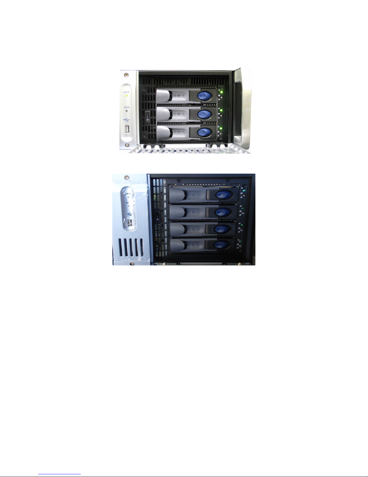
1.4.2 HDDs Shipment
• Hard disk drives (HDDs) might be shipped out of the chassis. In this case, insert them in
before plugging in the power cables according to the procedure presented below:
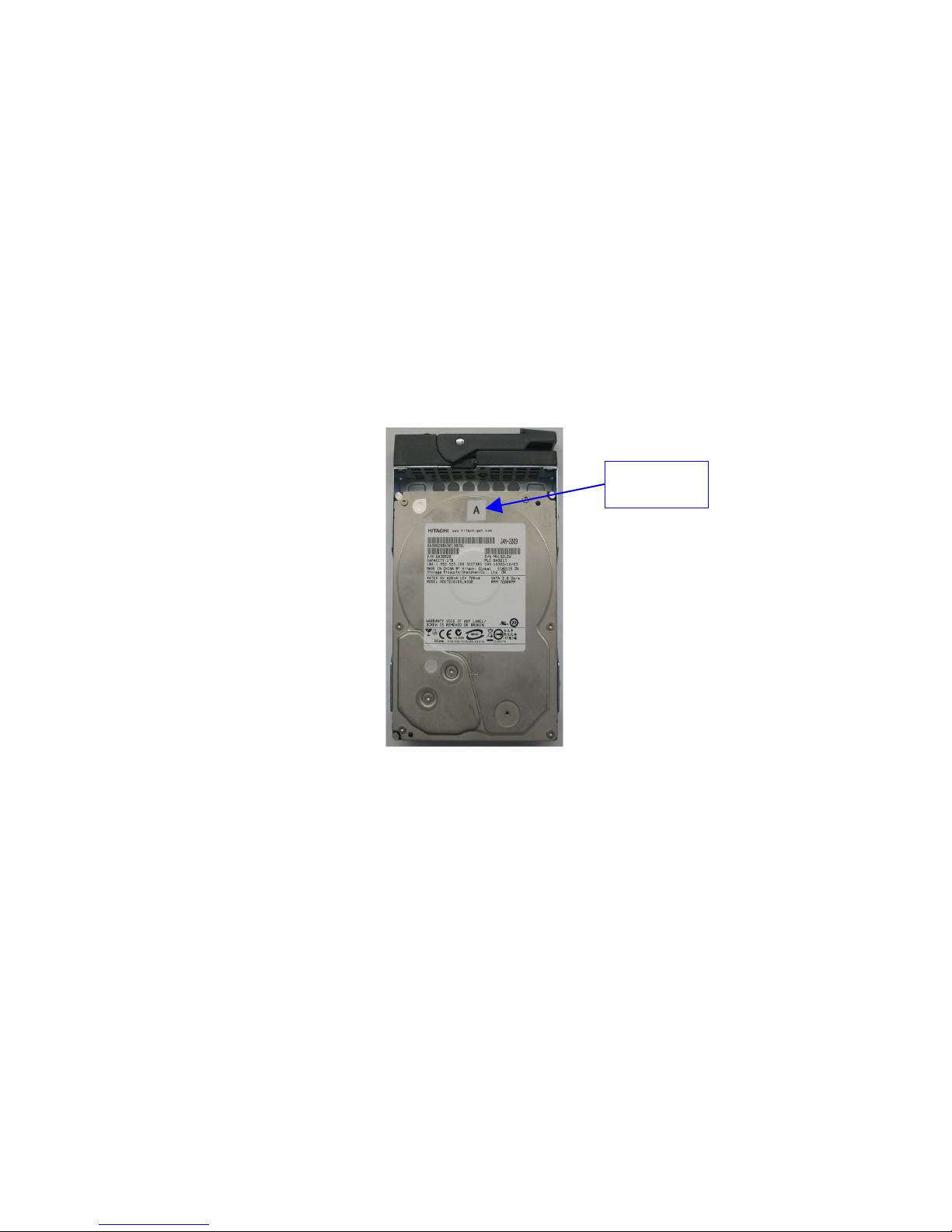
• Identify the label written on each HDD.
• There will be one HDD with "A", one HDD with "B", and one HDD with "C" written on
them (see Figure 1 below) .
HDD Label
Location
Figure 1: HDD Label Location With “A” Label
• For each HDD press on the blue button located on its front side in order to release the
gray handle.
• Open the gray handle all the way until it clicks (see Figure 2 below).
_____________________________________________________________________________________
SHV.OM.001293.DRM Page 12 Version 1.3
Doremi Cinema LLC Confidential
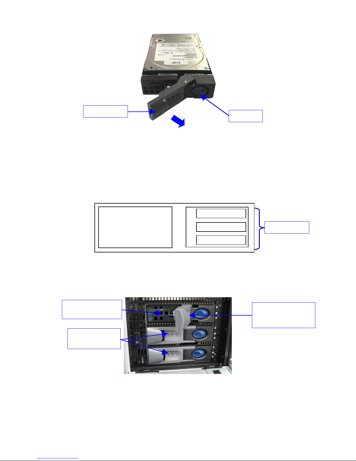
Gray handle
Blue button
Figure 2: HDD Gray Handle Opening
• Open the door covering the HDD case which is located on the right side of the front
panel.
• Insert each drive all the way – one by one – into the chassis HDD cage according to the
A-B-C location defined in the schema below.
• The gray handle must remain open all the way.
A
LCD monitor
B
C
HDD Location
Figure 3: ShowVault Front View Schema – HDD
• The drive must be inserted all the way inside the HDD cage before trying to close the
gray handle.
"A" HDD inserted into
the HDD cage
"B" and "C" HDDs
already installed
Gray handle opened to
insert the HDD
properly
Figure 4: ShowVault HDD Insertion
• Close the gray handle by pushing it toward the HDD until it clicks.
_____________________________________________________________________________________
SHV.OM.001293.DRM Page 13 Version 1.3
Doremi Cinema LLC Confidential

• The HDD properly installed will look like the "A", "B", and "C" HDDs presented in Figure
4 above.
• Power cables can now be plugged safely into the ShowVault.
1.5 Proper Power Off
Follow the instruction below to power off the ShowVault safely. Any other method might damage
the RAID and result in RAID failure.
• Select "Shut Down" from the "Logout" menu: "Menu → Logout... → Shutdown".
• Another method to power off the unit is to press and release the power button.
• To turn the unit back on simply press and release the power switch.
Note: Do not press and hold the power off button for more than a second. See Section 2.1 for
power switch location.
1.6 Contact
If in need of help or assistance, please contact Doremi Labs Technical Support at:
USA
• 24/7 Technical Support line: +1-866-484-4004
• Technical Support Email: support@doremicinema.com
Europe
• 24/7 Technical Support line: +33 (0) 492-952-847
• Technical Support Link: http://support.doremitechno.org/ticketing
Japan
• Technical Support line: +044-966-4855
• Technical Support Email: support@doremilabs.co.jp
Australia ~ China ~ India ~ Indonesia ~ Korea ~ Malaysia ~ New Zealand ~ Philippines ~
Singapore ~ Taiwan ~ Thailand
• Technical Support Email: supportasia@doremilabs.com
_____________________________________________________________________________________
SHV.OM.001293.DRM Page 14 Version 1.3
Doremi Cinema LLC Confidential
2 ShowVault Presentation
Thank you for choosing the Doremi ShowVault. The ShowVault is a high quality DCI JPEG2000 server capable of playing movie or trailer packages in MXF format at up to 250Mbits/sec.
The unit features a PCI-Express cable to interface with the IMB unit installed in the projector.
This interface is used to transfer digital cinema files to the IMB which is capable of 12-bit 4:4:4
2048x1080p24 or 10-bit 4:2:2 for 48fps and 3D applications. Data storage is done on an internal
RAID5 disk array.
The ShowVault also supports MPEG2 Interop movies, pre-show, and alternative content
playback.
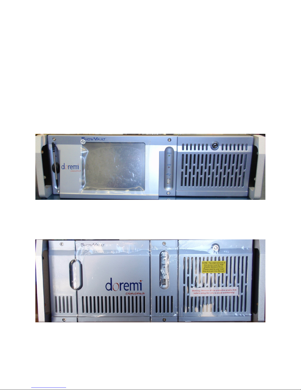
2.1 ShowVault Front Panel
• A silver front panel with a LCD screen is shown below:
Figure 5: ShowVault (3RU) with Silver Front Panel
• A blue front panel without LCD screen is shown below:
Figure 6: ShowVault (4RU) with Blue Front Panel
• POWER (PWR): The LED lights turn green when the unit is powered on.
_____________________________________________________________________________________
SHV.OM.001293.DRM Page 15 Version 1.3
Doremi Cinema LLC Confidential
• HDD: Red LED light indicate access to the Hard Disk Drives.
• The door on the right on both types of units (3RU and 4RU) covers the "POWER" switch
and the three hard disks that make up the RAID5 storage.
Figure 7: ShowVault (3RU) Silver Front Panel Right Door Opened
Figure 8: ShowVault (4RU) Blue Front Panel Right Door Opened
• Each hard disk drive has a blue button that allows removal of the drive from the chassis.
• Be careful not to remove the hard disk drive when the ShowVault is running.
• There is one USB 2.0 connector on the center of the front panel that can accommodate
an external hard drive as well as a mouse or keyboard.
• The left side of the front panel contains an LCD screen (3RU only).
_____________________________________________________________________________________
SHV.OM.001293.DRM Page 16 Version 1.3
Doremi Cinema LLC Confidential
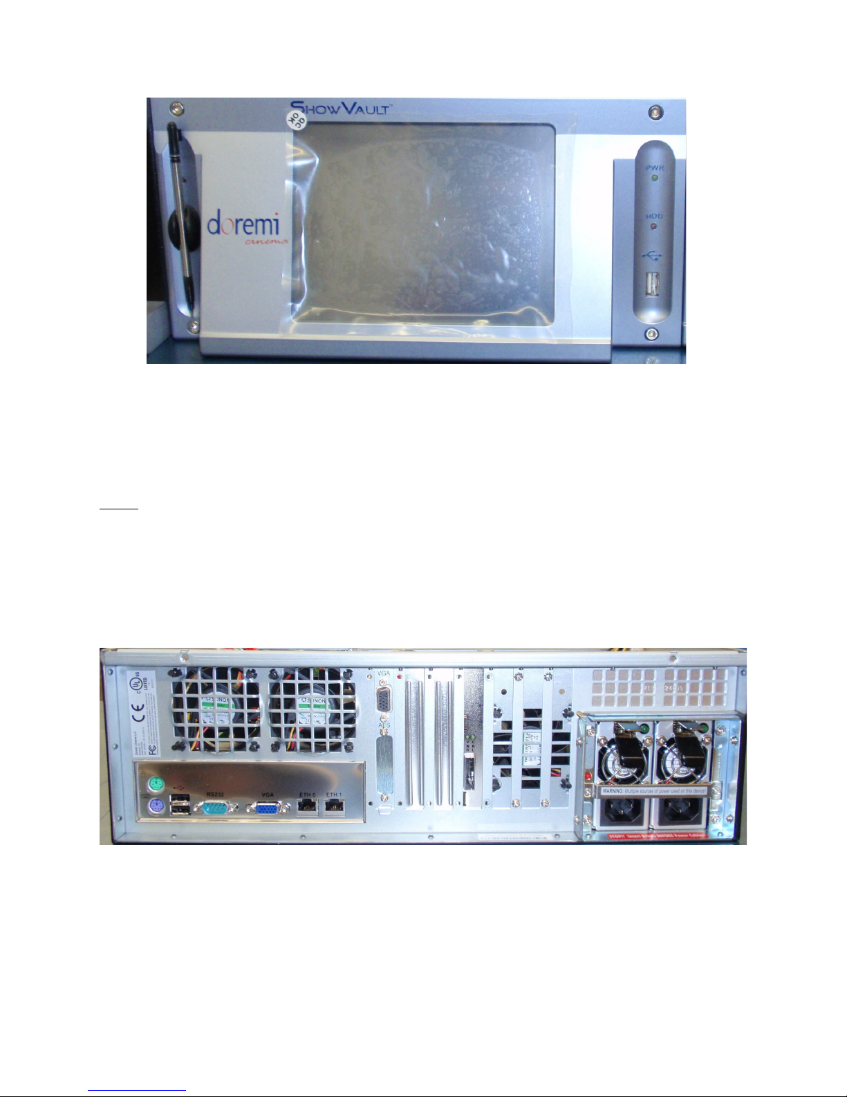
Figure 9: ShowVault (3RU) Silver Front Panel LCD Screen
• On the silver front panel the LCD can be turned on or off by pressing on the LCD power
button using the stylus attached to the front panel. This button is located behind the
stylus (see Figure 9 above).
Note: The use of the LCD screen requires that the two rear panel VGA connectors are linked
using the VGA cable provided with the ShowVault. See paragraph 3.1 for details about the VGA
cable connections.
2.2 ShowVault Rear Panel
The rear panel will differ on the ShowVault depending on the motherboard used. The
SuperMicro motherboard usage is illustrated in Figure 10 below.
Figure 10: ShowVault (3RU) Rear Panel Fitted With A SuperMicro Motherboard
_____________________________________________________________________________________
SHV.OM.001293.DRM Page 17 Version 1.3
Doremi Cinema LLC Confidential
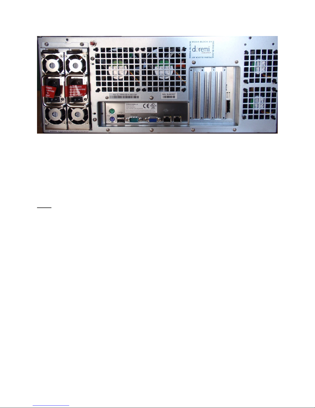
Figure 11: ShowVault (4RU) Rear Panel Fitted With A SuperMicro Motherboard
• On the left side on the rear panel is the dual-redundant power supply
• Make sure that two AC power cables are used or the unit will sound an audible alarm
until both power cables are connected
• To temporarily disable the audible alarm press the red button next to the AC power
connectors
Note: Insert drives before connecting power cables. Powering the ShowVault with only one AC
cable is not recommended.
• On the left side on the rear panel are the motherboard connections The motherboard
connections are for the keyboard, mouse, VGA, 9-pin serial, Ethernet and USB 2.0
connections - see Section 3.3 for detailed information on motherboard connections
_____________________________________________________________________________________
SHV.OM.001293.DRM Page 18 Version 1.3
Doremi Cinema LLC Confidential
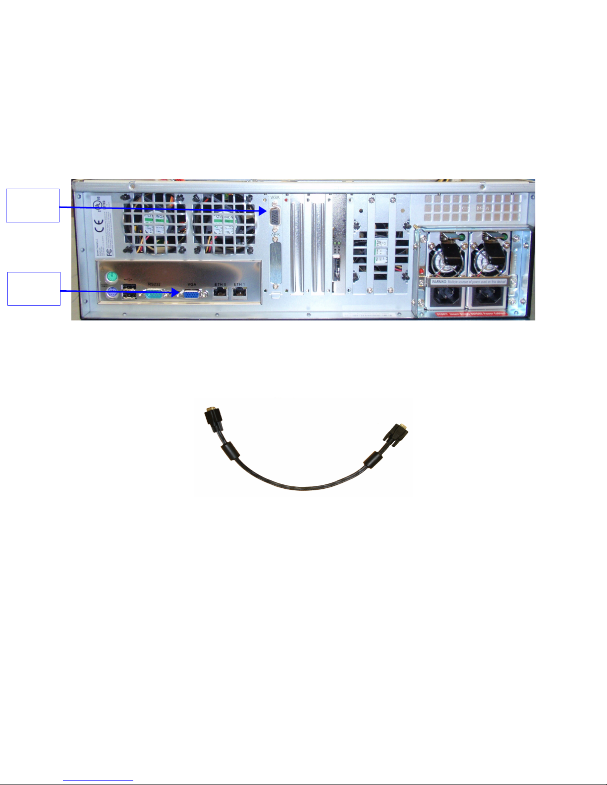
VGA
Connector
VGA
Connector
3 Rear Panel Connectors
3.1 VGA Cable Connection for Server LCD Screen Usage
If the front panel LCD screen needs to be used (3RU only), the server LCD screen VGA
connector has to be linked to the motherboard VGA connector using the VGA cable. It is
provided with the ShowVault. The VGA cable has to be secured to the ShowVault VGA
connectors using the integrated screws.
Figure 12: ShowVault (3RU) Rear Panel With SuperMicro Motherboard VGA Connector
_____________________________________________________________________________________
SHV.OM.001293.DRM Page 19 Version 1.3
Figure 13: VGA Cable
Doremi Cinema LLC Confidential
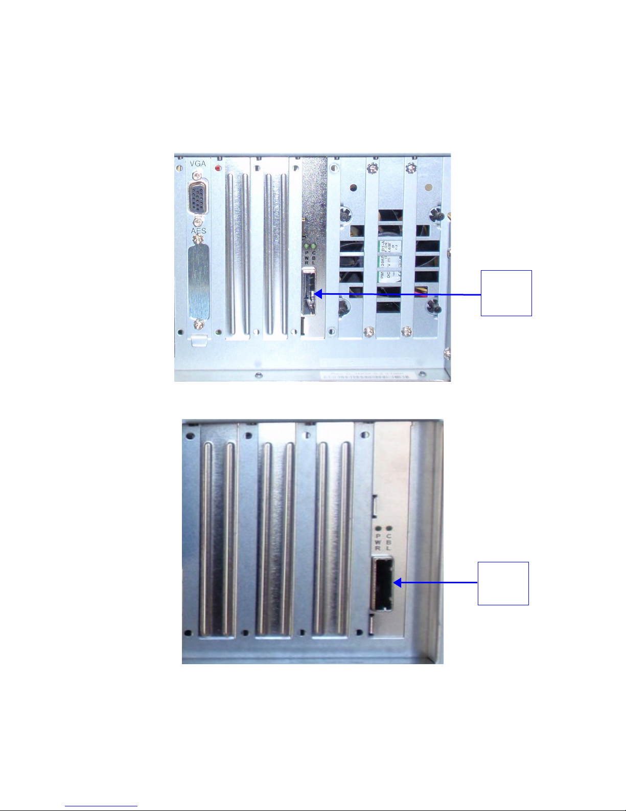
3.2 PCI Express Card On Rear Panel
3.2.1 PCI Express Card Overview
On the center of the rear panel are the various card slot connectors. The PCI Express card is
used to connect the ShowVault to the IMB in the projector.
PCI
Express
Card Slot
Figure 14: ShowVault (3RU) Rear Panel PCI Express Card Slot Connector
PCI
Express
Card Slot
Figure 15: ShowVault (4RU) Rear Panel PCI Express Card Slot Connector
_____________________________________________________________________________________
SHV.OM.001293.DRM Page 20 Version 1.3
Doremi Cinema LLC Confidential
3.3 ShowVault Motherboard Connections
Ethernet
0
3.3.1 Motherboard Connectors
On the rear panel of both the 3RU and 4RU units are the connections to the motherboard. The
motherboard used on the ShowVault is the SuperMicro. The SuperMicro Motherboard
connector is presented in paragraph 3.3.1.1. The associated connectors are labeled and
described in the paragraphs 3.3.2 to 3.3.6.
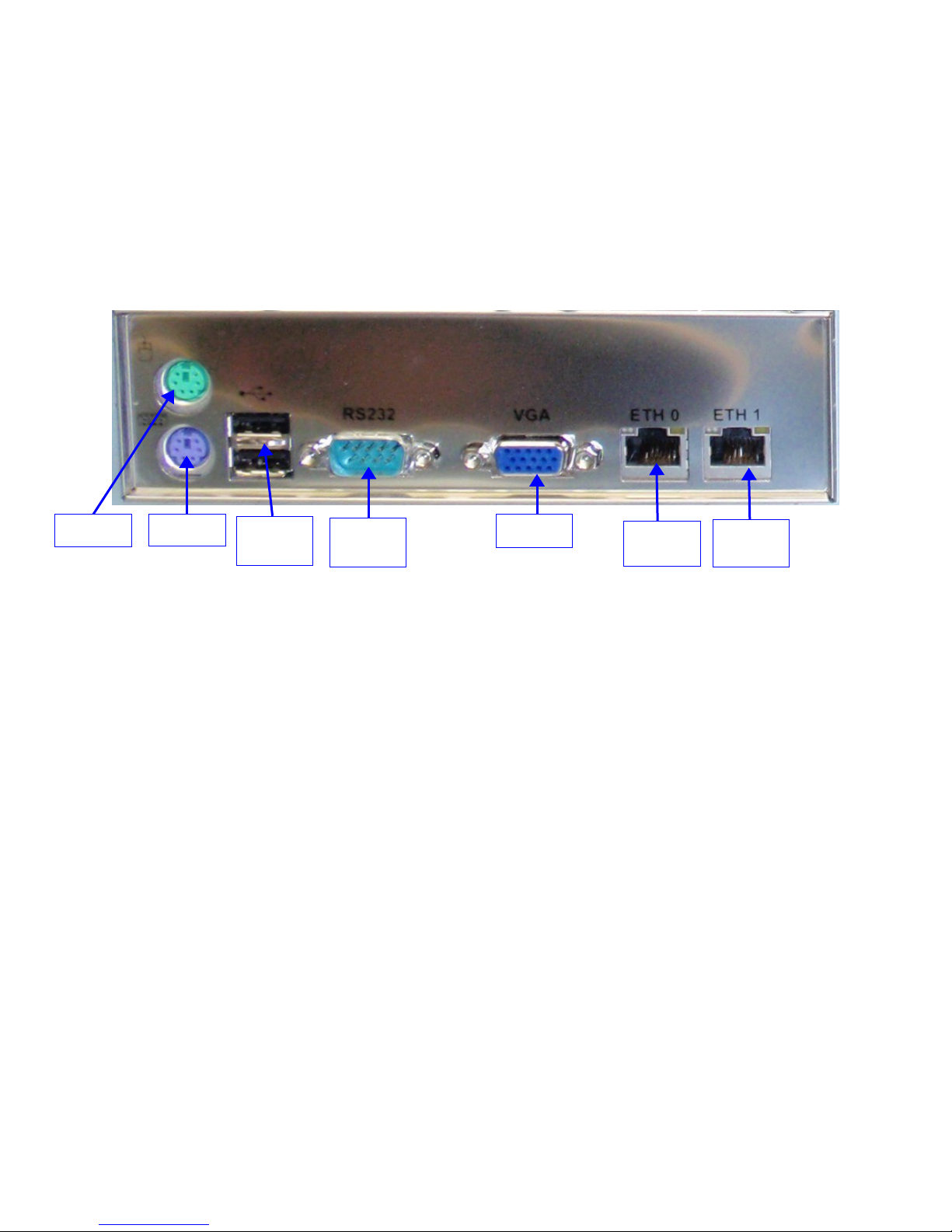
3.3.1.1 SuperMicro Motherboard Connectors
Mouse
Keyboard
USB
Ports
Serial
Port
VGA Port
Ethernet
Figure 16: ShowVault (3RU) Rear Panel SuperMicro Motherboard Connectors
3.3.2 Keyboard and Mouse PS-2 Connectors
On the left side of the connector panel are the PS-2 connectors for the PC keyboard and
mouse. These jacks can be used interchangeably, but traditionally the purple jack is for a PC
keyboard and the green jack is for a PS-2 mouse. If the user has a USB keyboard or mouse,
then use the USB ports on the left side of the motherboard connector panel.
3.3.3 Serial Port
This is a standard 9-pin male DB-9 serial COM port on the motherboard.
3.3.4 VGA
Connect a standard VGA monitor to display the ShowVault software interface.
This connector can also be linked to the center rear panel VGA connector to facilitate use of the
front panel LCD screen. The VGA cable is provided with the Showvault and is further explained
in section 3.1.
3.3.5 USB Ports
1
Connect standard USB 2.0 peripherals for a PC USB keyboard, mouse, hard drive, etc.
3.3.6 Ethernet
The Motherboard has two built-in Gigabit Ethernet connectors. The left one is identified as
"Eth0" and the right one is identified as "Eth1".
_____________________________________________________________________________________
SHV.OM.001293.DRM Page 21 Version 1.3
Doremi Cinema LLC Confidential
4 ShowVault IP Address
All ShowVault servers are shipped with a default IP address of 192.168.100.50 on the Ethernet
port (Eth1) and a DHCP assigned dynamic IP address on the Ethernet port (Eth0) – see section
3.3 to locate each Ethernet connector.
• To change the IP address of the ShowVault server, go to “Menu → System →
Networking Setup” and follow the steps below:
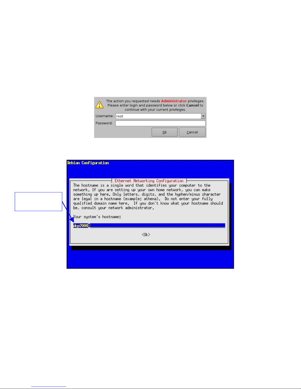
• From the ShowVault menu, select “Menu → System → Networking Configuration”
• A window will appear asking for a password as illustrated below:
Figure 17: Authentication Windows
• Follow the steps starting with the following windows:
System hostname -
"dcp2000" used as an
example
• In the steps that follow use the arrow down or the "Tab" key to select “OK” and then
press "Enter".
• Enter the desired system’s hostname and select “OK”.
• Select “OK” for the system’s domain name.
• Select “Yes” for eth0.
• Select “No” for "Removable Device".
Figure 18: ShowVault Network Configuration
• Select “No” for automatically configure device with DHCP.
• Enter the desired IP address for eth0 and select “OK”.
_____________________________________________________________________________________
SHV.OM.001293.DRM Page 22 Version 1.3
Doremi Cinema LLC Confidential

• Enter the desired default gateway or leave empty and select “OK”.
• Enter the desired subnet mask and select “OK”.
• Enter the desired Ethernet networking configuration and then select “OK”.
• Select “Yes” for eth1.
• Select “No” for "Removable device".
• Select “No” for automatically configure device with DHCP.
• Enter the IP address of eth1 and select “OK” – in the example, enter 192.168.10.12.
• Enter the desired default gateway or leave empty and select “OK”.
• Enter the desired subnet mask and select OK – in our example, enter the same subnet
mask as the projector: 255.255.255.0.
• Leave the system’s domain name servers empty and select “OK”.
• Exit the set up utility.
• To verify the setup go to “Menu → Doremi Apps. → Diagnostic Tool” and verify the IP
Address under the Diagnostic Tool “System” Tab.
Note: The configuration for Ethernet 2 that might be asked by the Ethernet configuration wizard
is not needed at this point. It is ok to skip this step if asked for the configuration.
_____________________________________________________________________________________
SHV.OM.001293.DRM Page 23 Version 1.3
Doremi Cinema LLC Confidential
5 Device Manager Set Up
The "Device Manager" is a graphical user interface (GUI) used to set up the connection
between a ShowVault and cinema projector(s). It also provides for the use of Ethernet
commands for the control of theater automation devices.
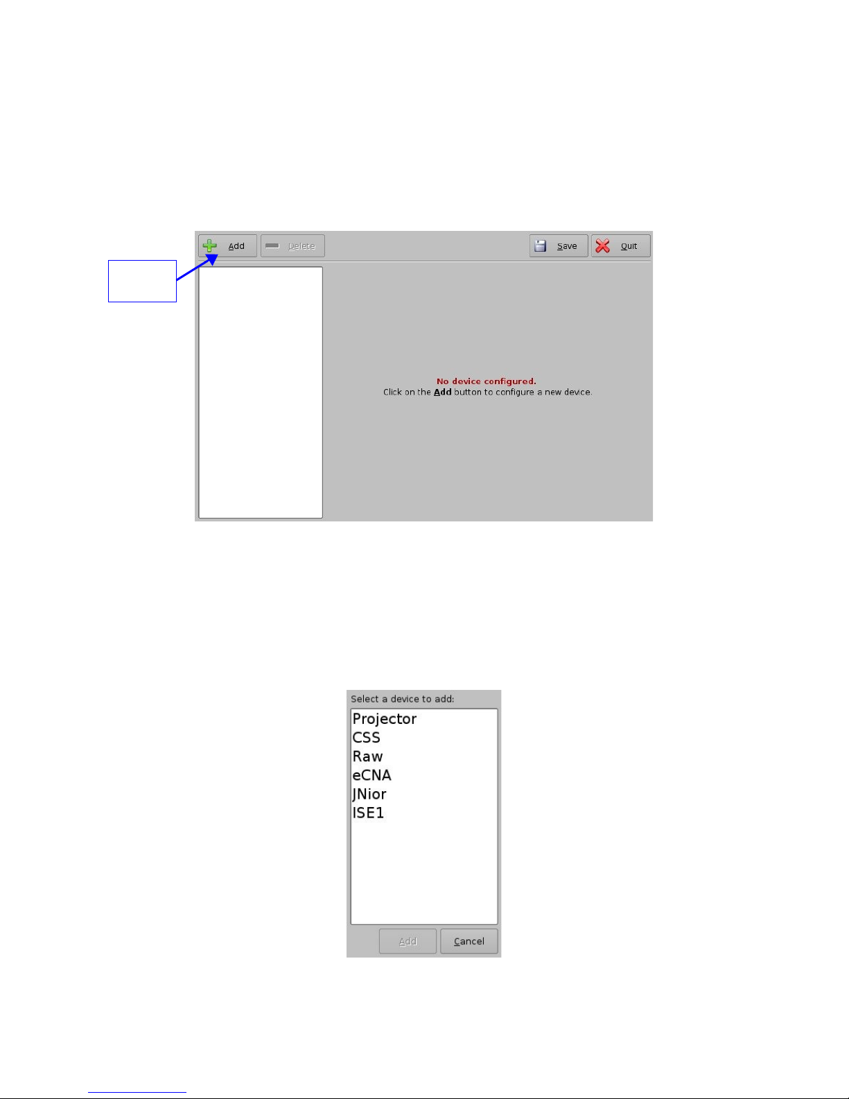
• To run the Device Manager go to “Menu → Doremi Apps. → Device Manager”
• The following window will appear on the screen:
“Add”
button
Figure 19: Device Manager Graphical User Interface (GUI)
5.1 Projector Management
5.1.1 Adding a Projector
• To connect a projector to the ShowVault click the “Add” button (see Figure 19 above)
• The following window will appear:
Figure 20: Device Manager GUI – Device Selection Window
_____________________________________________________________________________________
SHV.OM.001293.DRM Page 24 Version 1.3
Doremi Cinema LLC Confidential
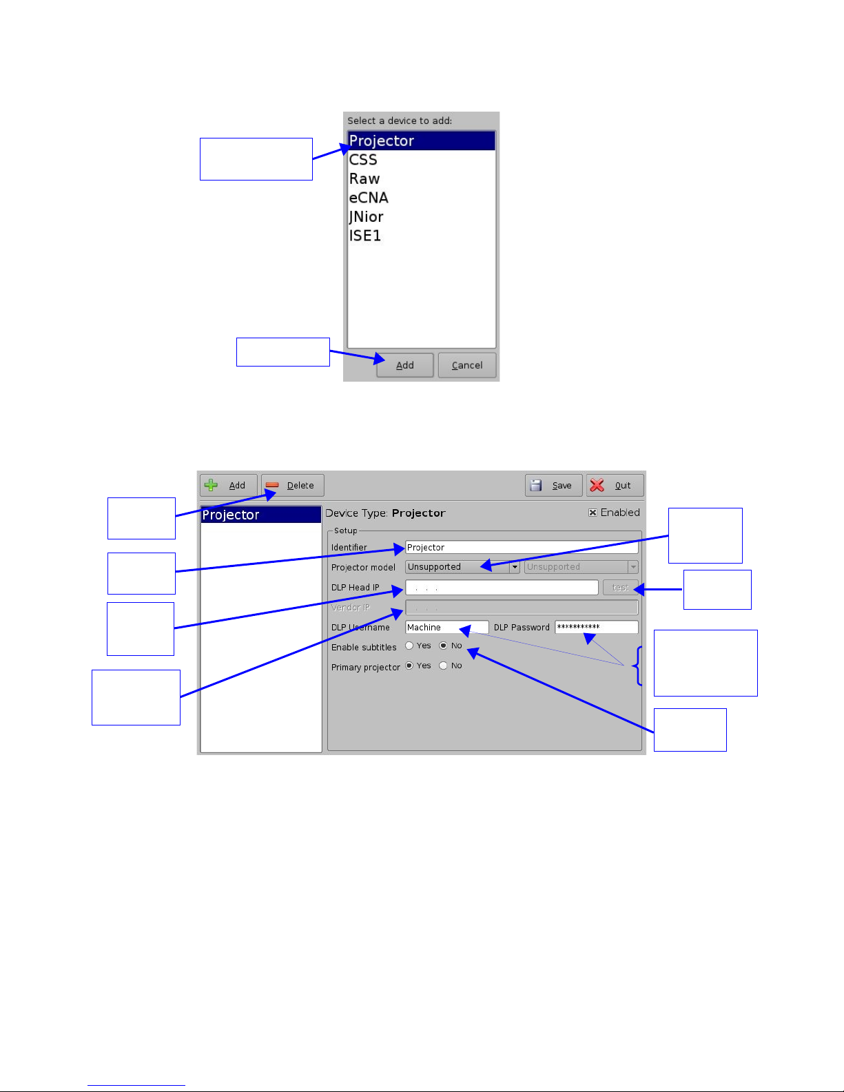
• Select the item called “Projector” and click the “Add” button as illustrated below:
“Projector” item
selected
“Add” button
Figure 21: Device Selection Window – “Projector” Item Selected
• User will then be back to the main configuration window and be able to enter the
projector parameters as highlighted below:
“Delete”
button
"Projector
Identifier"
“DLP
Head IP
Field"
"Vendor IP"
Field (not
used)
“Projector
model
Field"
"DLP" Username
and Password
(do not change)
"Enable
subtitles"
Figure 22: Device Manager GUI – Projector Fields Setup
• To perform the projector set up follow the steps below:
• Specify a projector identifier (projector name, screen #, 3D-left, and 3D-right) in the first
field
• Choose the correct projector model to connect to the ShowVault using the “Projector
model” field(s)
"Test"
Button
• Select "Series 2" for the projector from the drop-down menu on the right
_____________________________________________________________________________________
SHV.OM.001293.DRM Page 25 Version 1.3
Doremi Cinema LLC Confidential

• Enter the "DLP Head IP" address and then click the “test” button
Note: If user enables subtitles without the ShowVault being connected to a projector the server
will not operate properly.
• Specify if this is the primary projector or not using the corresponding radio button
Note: The "DLP Username and Password" are not used.
• Check the “Enabled” check box at the top right corner of the GUI
• Click the “Save” button to record these settings
• A password confirmation page will appear, enter the password to save and record the
settings
5.1.2 Removing a Projector
• To remove a projector click on its name on the left part of the "Device Manager" GUI
• Click the “Delete” button (see Figure 22 above)
5.2 Automation Libraries Management
Support for theater automation control is also provided. The list of currently supported devices is
the following:
• eCNA
• JNior
A pre-built library of supported automation commands is available for each of these two devices.
These automation commands can then be added to Macro Cues as presented in Section 6.2.
5.2.1 eCNA Device
5.2.1.1 eCNA Device Addition
• To use the eCNA device click the “Add” button and select “eCNA”
• Enter the eCNA device IP address in the appropriate field as presented below:
_____________________________________________________________________________________
SHV.OM.001293.DRM Page 26 Version 1.3
Doremi Cinema LLC Confidential
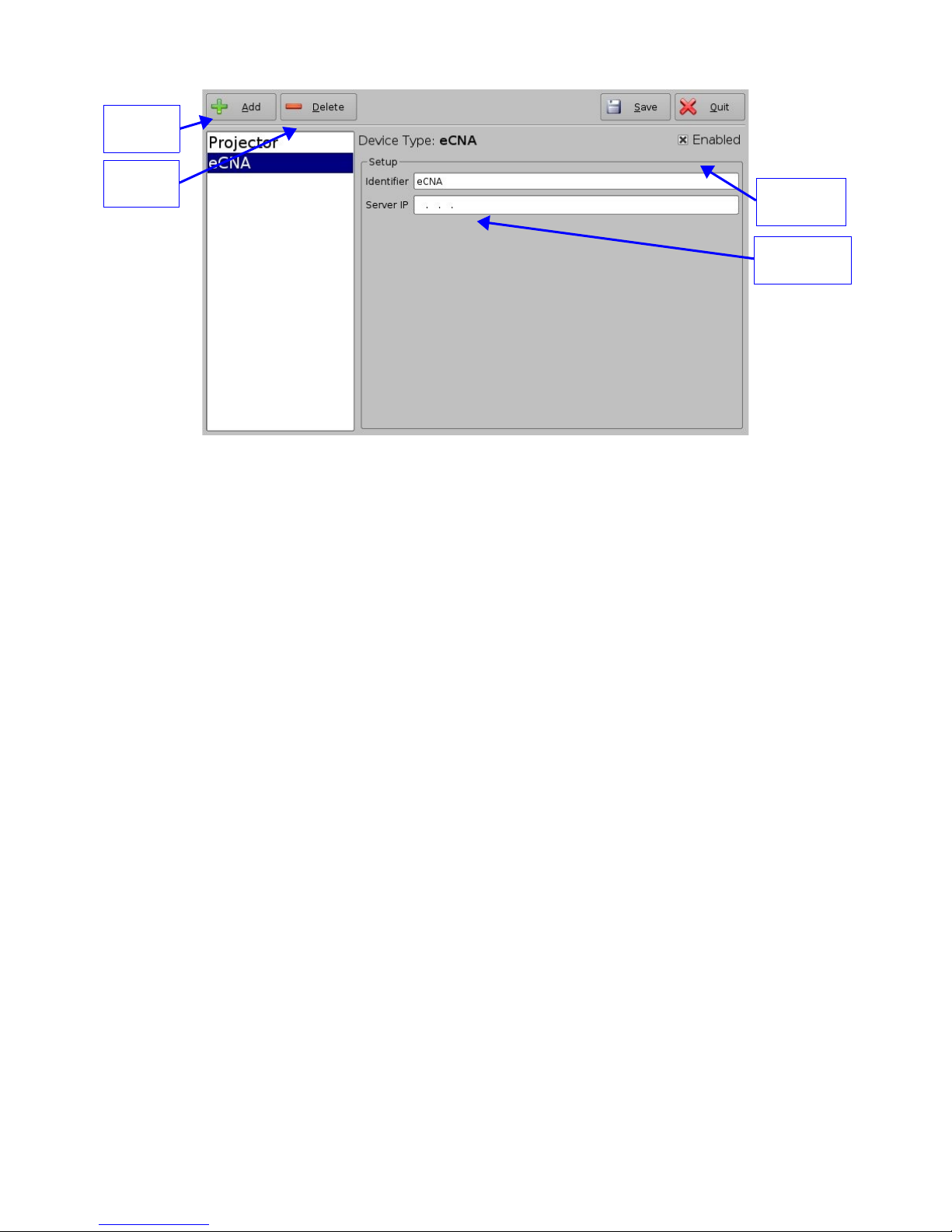
“Add”
button
“Delete”
button
Figure 23: Device Manager GUI – eCNA Device Setup
• The “Enabled” field must be checked in the top-right corner of the GUI
• Click the “Save” button to record the settings
• A window asking for the password will appear
“Enabled”
checked
eCNA IP
address field
• Enter the password to save settings and proceed
5.2.1.2 eCNA Device Removal
• To remove the eCNA device select it in the left pane of the "Device Manager" and click
the “Delete” button (see Figure 23 above)
5.2.2 JNior Device
5.2.2.1 JNior Device Addition
• To use the JNior device click the “Add” button and select “JNior”
• The "JNior" device setting window will be displayed within the "Device Manager" as
presented below:
_____________________________________________________________________________________
SHV.OM.001293.DRM Page 27 Version 1.3
Doremi Cinema LLC Confidential
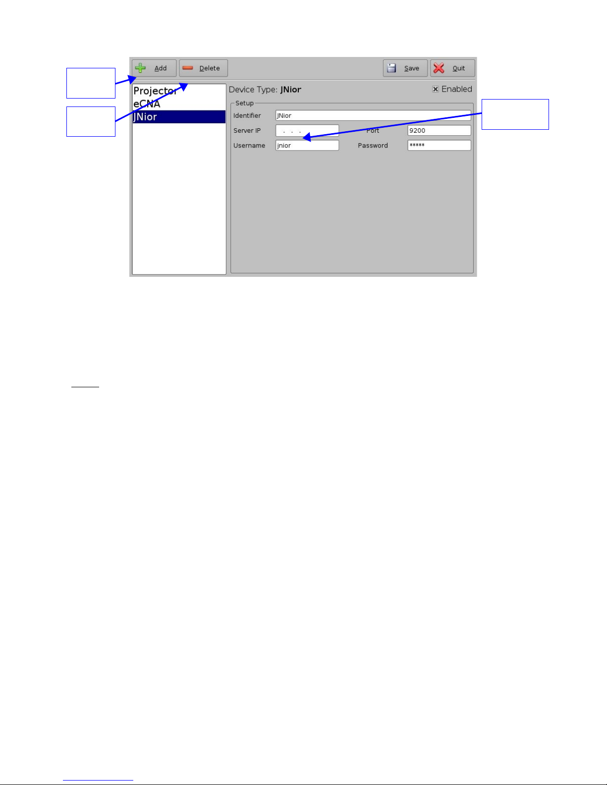
“Add”
button
“Delete”
button
JNior IP
address field
Figure 24: Device Manager GUI – JNior Device Setup
• Enter the IP address of the "JNior" device in the “Server IP” field
• The port number field should already contain the appropriate value (factory default
value)
Note: The "JNior" device documentation will provide the correct username and password
(factory default values).
• Click the “Save” button to record the settings
• A window will appear asking for a password, enter the password to proceed
5.2.2.2 JNior Device Removal
• To remove the JNior device click on its name on the left part of the "Device Manager"
GUI
• Click the “Delete” button (see Figure 24 above)
5.3 Raw Device
5.3.1 Raw Device Addition
A “Raw” device allows for communication with an external device across an Ethernet connection
using "Raw" data formatted as text or binary strings.
• To use a "Raw" device click the “Add” button and select “Raw”
• The "Raw" device setting window will be displayed within the "Device Manager" as
presented below:
_____________________________________________________________________________________
SHV.OM.001293.DRM Page 28 Version 1.3
Doremi Cinema LLC Confidential
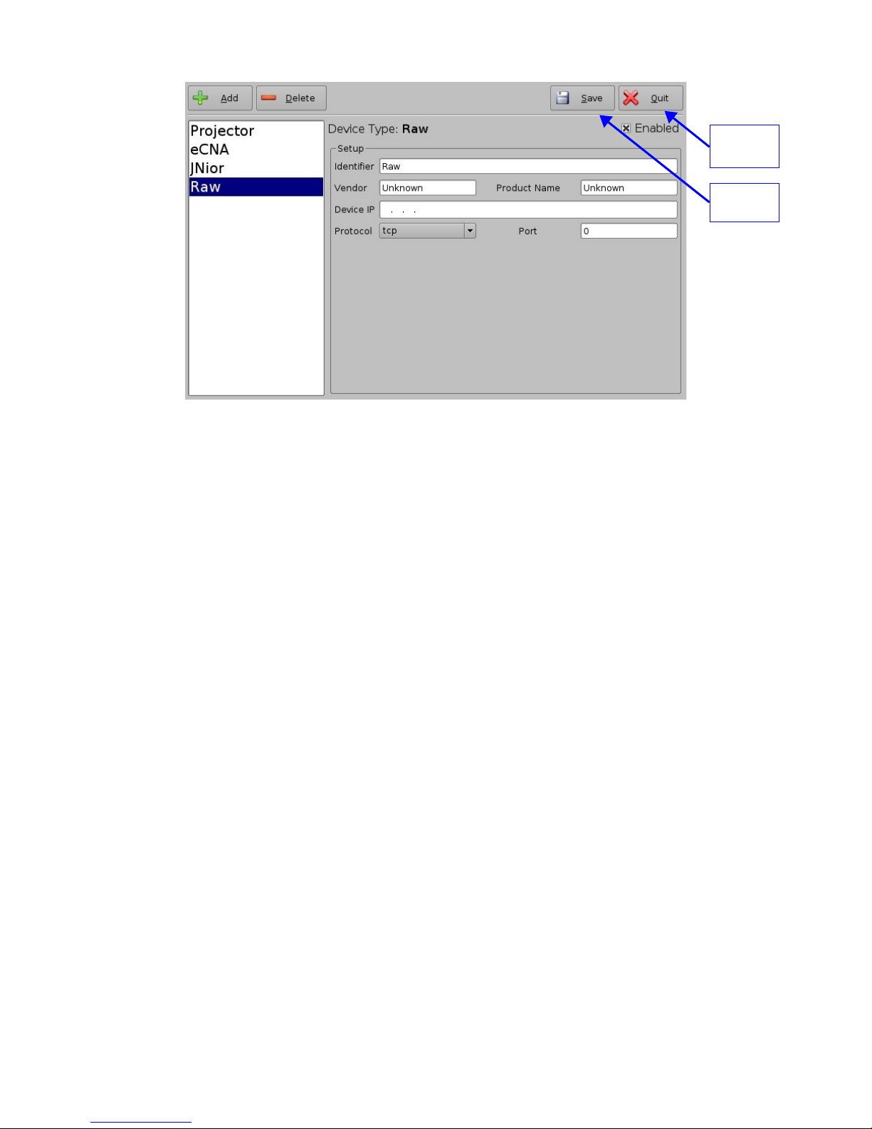
“Quit”
button
button
“Save”
Figure 25: Device Manager GUI – Raw Device Set Up
• Enter the IP address of the "Raw" device in the “Device IP” field (see Figure 25 above)
• Chose the protocol to be used (TCP or UDP) and the proper Port number
• Click the “Save” button to record the settings (see Figure 25 above)
• A window will appear asking for a password, enter the password to proceed
• If finished with the configuration then click the "Quit" button and save the settings
5.3.2 Raw Device Removal
• To remove the "Raw" device click on its name on the left part of the "Device Manager"
GUI and press the “Delete” button (see Figure 25 above)
5.4 ISE1 Device
The ISE1 Device provides for communication with the IMAX Secure Enclosure. If more
information is needed, please contact Doremi Technical Support.
5.5 CSS Device
The CSS Device provides for communication with the Sony Cavity Security System. If more
information is needed, please contact Doremi Technical Support.
5.6 3D Set Up
5.6.1 Projector Configuration for 3D or 48fps
When using a ShowVault/IMB configuration for 3D presentation the projector needs to be set to
the proper color space. Contact the projector vendor to know how to configure the projector
properly.
_____________________________________________________________________________________
SHV.OM.001293.DRM Page 29 Version 1.3
Doremi Cinema LLC Confidential

5.6.2 Dolby 3D Support
To enable the Dolby 3D support please contact Doremi to purchase the appropriate license.
Then go to Section 8.3 to install the license in the ShowVault and to Section 14.1 to know how
to configure the Dolby DFC100 device through "Device Manager".
5.6.3 RealD 3D Support
To enable the RealD 3D support, please contact Doremi to get the appropriate license. Then go
to Section 8.3 to install the license in the ShowVault and to Section 14.2 to know how to
configure the “RealD 3D EQ” device through "Device Manager".
5.6.4 Sensio 3D Support
To enable the Sensio 3D support, please contact Doremi to get the appropriate license. Then go
to Section 8.3 to install the license in the ShowVault and contact Doremi Technical Support
Services to know how to configure a playback using Sensio 3D.
5.7 Closed Caption Support
To enable the Rear Window devices Closed Caption support, install the appropriate license as
explained in Section 8.3. For information about set up contact Doremi Technical Support.
_____________________________________________________________________________________
SHV.OM.001293.DRM Page 30 Version 1.3
Doremi Cinema LLC Confidential
 Loading...