

Page 1

IMS1000
Installation and User Manual
Version 1.7
The English version of this document is the only legally binding version.
Translated versions are not legally binding and are for convenience only.
IMS.OM.002949.DRM Page 1 of 320 Version 1.7
Doremi Labs
Page 2

Table of Contents
1 Introduction ......................................................................................................................23
1.1 Purpose ...................................................................................................................................... 23
1.2 Software Version ...................................................................................................................... 23
1.3 Contact Technical Support...................................................................................................... 23
2 ESD Rules .........................................................................................................................25
3 IMS1000 Overview ............................................................................................................27
3.1 IMS1000 Key Features and Functions .................................................................................. 27
3.1.1 JPEG2000 DCI DCP playback ....................................................................................... 27
3.1.2 MPEG2/H264/VC1 MXF Interop: ................................................................................... 28
3.1.3 Video processing features: ............................................................................................. 28
3.1.4 Security .............................................................................................................................. 28
3.1.5 Audio .................................................................................................................................. 28
3.1.6 Alternative Content ........................................................................................................... 28
3.1.7 Pre-Loaded Test Content ................................................................................................ 28
3.2 Input / Output Ports .................................................................................................................. 28
3.3 Environmental Specifications ................................................................................................. 29
3.4 Performance / Storage / Power .............................................................................................. 29
3.5 IMS1000..................................................................................................................................... 29
3.6 IMS1000 Faceplate Overview ................................................................................................ 29
4 Installation and Marriage with a NEC Series-2 Projector ..............................................34
4.1 Preparation ................................................................................................................................ 34
4.2 HDDs .......................................................................................................................................... 38
4.3 Reattaching the Projector Covers .......................................................................................... 40
IMS.OM.002949.DRM Page 2 of 320 Version 1.7
Doremi Labs
Page 3

4.4 Audio Cables Installation ......................................................................................................... 41
4.5 GPI/GPO Cables Installation .................................................................................................. 42
4.5.1 GPI/GPO Pin-Out Information ........................................................................................ 43
4.6 Ethernet Cables ........................................................................................................................ 43
4.7 Power on Projector ................................................................................................................... 44
4.8 Accessing the GUI ................................................................................................................... 44
4.9 Configuring the Device ............................................................................................................ 45
4.10 Marriage ..................................................................................................................................... 47
5 Installation and Marriage with a Barco Series-2 Projector ............................................53
5.1 Preparation ................................................................................................................................ 53
5.2 HDDs .......................................................................................................................................... 55
5.3 Audio Cables Installation ......................................................................................................... 57
5.4 GPI/GPO Cables Installation .................................................................................................. 58
5.4.1 GPI/GPO Pin-Out Information ........................................................................................ 58
5.5 Ethernet Cables ........................................................................................................................ 59
5.6 Power on Projector ................................................................................................................... 60
5.7 Accessing the GUI ................................................................................................................... 60
5.8 Configuring the Device ............................................................................................................ 61
5.9 Marriage ..................................................................................................................................... 63
6 Installation and Marriage with a Christie Series-2 Projector .........................................66
6.1 Preparation ................................................................................................................................ 66
6.2 HDDs .......................................................................................................................................... 68
6.3 Audio Cables Installation ......................................................................................................... 70
6.4 GPI/GPO Cables Installation .................................................................................................. 71
IMS.OM.002949.DRM Page 3 of 320 Version 1.7
Doremi Labs
Page 4

6.4.1 GPI/GPO Pin-Out Information ........................................................................................ 72
6.5 Ethernet Cables ........................................................................................................................ 72
6.6 Power on Projector ................................................................................................................... 73
6.7 Accessing the GUI ................................................................................................................... 75
6.8 Configuring the Device ............................................................................................................ 76
6.9 Marriage ..................................................................................................................................... 78
7 Shut Down ........................................................................................................................83
8 Operating System ............................................................................................................85
8.1 Users .......................................................................................................................................... 86
9 Network Configuration ....................................................................................................88
9.1 Default Network Configuration ............................................................................................... 88
9.2 Changing the IP Address ........................................................................................................ 88
9.3 Network Reset .......................................................................................................................... 90
10 Time Zone Configuration .................................................................................................91
10.1 Checking the Time Zone ......................................................................................................... 91
10.2 Changing the Time Zone ......................................................................................................... 92
10.3 Changing the System Time .................................................................................................... 92
10.4 NTP Servers .............................................................................................................................. 94
11 Overview Tab ...................................................................................................................96
11.1 Notification Bar ......................................................................................................................... 96
11.1.1 Quick Controls .................................................................................................................. 96
11.1.2 Playback ............................................................................................................................ 97
11.1.3 Ingest .................................................................................................................................. 98
11.1.4 Session Viewer ................................................................................................................. 99
IMS.OM.002949.DRM Page 4 of 320 Version 1.7
Doremi Labs
Page 5

11.1.5 Notifications ....................................................................................................................... 99
12 Administration Tab ........................................................................................................ 102
12.1 Audio Settings/Channel Mapping ........................................................................................ 103
12.2 Channel Mapping Tab ........................................................................................................... 104
12.2.1 Disabled Configuration .................................................................................................. 104
12.2.2 Pre-Defined Mapping Configurations .......................................................................... 105
12.2.2.1 Four Channels ........................................................................................................ 105
12.2.2.2 Six Channels ........................................................................................................... 106
12.2.2.3 Seven Channels ..................................................................................................... 107
12.2.2.4 Eight Channels........................................................................................................ 108
12.2.2.5 Nine Channels ........................................................................................................ 109
12.2.2.6 ISDCF ....................................................................................................................... 110
12.2.2.7 Passthrough Configuration ................................................................................... 111
12.2.2.8 Custom Mapping Configuration ............................................................................ 111
12.2.3 SMPTE Packages .......................................................................................................... 113
12.2.4 Audio Delay Configuration ............................................................................................ 114
12.2.5 Interop Packages............................................................................................................ 115
12.3 Device Manager ..................................................................................................................... 116
12.3.1 Adding a Projector .......................................................................................................... 116
12.3.1.1 Removing a Device or Projector .......................................................................... 118
12.3.2 Automation Libraries Management .............................................................................. 118
12.3.3 Adding an eCNA Device................................................................................................ 118
12.3.3.1 Removing an eCNA Device .................................................................................. 119
12.3.4 Adding a JNior Device ................................................................................................... 119
IMS.OM.002949.DRM Page 5 of 320 Version 1.7
Doremi Labs
Page 6

12.3.4.1 Removing a JNior Device ...................................................................................... 120
12.3.5 Adding a Raw Device .................................................................................................... 120
12.3.5.1 Removing a Raw Device ....................................................................................... 121
12.3.6 Adding 3D Systems........................................................................................................ 121
12.3.6.1 Dolby 3D Support ................................................................................................... 121
12.3.6.2 RealD 3D Support .................................................................................................. 122
12.3.6.3 Sensio 3D Support ................................................................................................. 122
12.3.7 Closed Caption Support ................................................................................................ 122
12.3.8 Subtitle Engine Configuration ....................................................................................... 122
12.3.9 Missing License .............................................................................................................. 123
12.4 Macro Editor ............................................................................................................................ 125
12.4.1 Automation Cues ............................................................................................................ 125
12.5 Macro Automation Cues ........................................................................................................ 125
12.5.1 Macro Creation Using Macro Editor ............................................................................ 125
12.5.2 Editing a Macro Automation Cue ................................................................................. 126
12.5.3 Inserting Actions into Macro Cues ............................................................................... 127
12.5.4 Add a GPO Action to the Macro Automation Cue ..................................................... 128
12.5.5 Playback Action Insertion .............................................................................................. 128
12.5.6 Video Output Action Insertion ....................................................................................... 129
12.5.7 Dowser Action Insertion ................................................................................................ 129
12.5.8 Projector Channel Switch Insertion ............................................................................. 130
12.5.9 Automation Library Usage ............................................................................................ 130
12.5.9.1 Using Automation Library ...................................................................................... 130
12.5.9.2 Resulting Macro Setting ........................................................................................ 131
IMS.OM.002949.DRM Page 6 of 320 Version 1.7
Doremi Labs
Page 7

12.5.10 Action List Management ............................................................................................ 132
12.5.10.1 Action Re-Ordering ................................................................................................ 132
12.5.10.2 Action Edition .......................................................................................................... 132
12.5.10.3 Action and Macro Removal ................................................................................... 132
12.5.11 Macro Saving .............................................................................................................. 132
12.5.12 Add a Macro to a Show Playlist ............................................................................... 132
12.6 Trigger Cue Tab ..................................................................................................................... 133
12.6.1 Trigger Cue Tab Overview ............................................................................................ 133
12.6.2 Trigger Cue Creation ..................................................................................................... 133
12.6.3 Connection to a General Purpose Input Event .......................................................... 135
12.6.4 Connection to a Signal Event ....................................................................................... 136
12.6.5 Editing and Deleting the Event ..................................................................................... 137
12.6.6 Trigger Cue Saving ........................................................................................................ 137
12.6.7 Pre-Defined Macro Usage ............................................................................................ 138
12.6.8 Default Cues ................................................................................................................... 138
12.6.9 Startup Scripts ................................................................................................................ 138
12.6.10 Add a Trigger Cue to a Show Playlist ..................................................................... 138
12.7 Quick Controls ........................................................................................................................ 139
12.7.1 Creating Macros ............................................................................................................. 139
12.7.2 Setting up Quick Controls ............................................................................................. 139
12.7.3 Executing the Quick Controls ....................................................................................... 141
12.8 Content Feed Manager ......................................................................................................... 143
12.8.1 Quick Configuration........................................................................................................ 143
12.8.1.1 Advanced Options .................................................................................................. 143
IMS.OM.002949.DRM Page 7 of 320 Version 1.7
Doremi Labs
Page 8

12.8.2 Adding a Server Manually ............................................................................................. 144
12.8.2.1 Networking the Server(s) ...................................................................................... 144
12.8.2.2 Advanced Options .................................................................................................. 145
12.8.3 Deleting a Server ............................................................................................................ 145
12.8.4 Ingesting from a Server That Was Added .................................................................. 145
12.9 Terminal ................................................................................................................................... 147
12.10 System ................................................................................................................................. 148
12.11 Log Operator Maintenance ............................................................................................... 149
12.11.1 Event Log Tab ............................................................................................................. 149
12.11.2 Scheduled Tasks Tab ................................................................................................ 151
12.12 Account Manager GUI ....................................................................................................... 152
12.12.1 Add a New User Account .......................................................................................... 152
12.12.2 Edit an Existing User Account .................................................................................. 154
12.12.3 Delete An Existing User Account ............................................................................. 154
12.13 Theater Properties.............................................................................................................. 155
12.13.1 Auditorium Tab ........................................................................................................... 155
12.13.2 Contacts Tab ............................................................................................................... 156
12.13.3 Facility Tab .................................................................................................................. 157
12.14 Quick Access Links ............................................................................................................ 158
12.15 Cinelister Configuration ..................................................................................................... 161
12.15.1 Editor Configuration ................................................................................................... 161
12.15.2 Scheduler Configuration ............................................................................................ 162
12.16 Live Manager ...................................................................................................................... 163
12.16.1 Creating a Live Event ................................................................................................ 163
IMS.OM.002949.DRM Page 8 of 320 Version 1.7
Doremi Labs
Page 9

12.16.2 Live Event in Cinelister .............................................................................................. 165
12.16.3 Deleting a Live CPL ................................................................................................... 166
12.17 Backup Manager ................................................................................................................ 167
12.17.1 Automatic Backup of System .................................................................................... 167
12.17.1.1 Viewing the Backup File Record(s) ..................................................................... 167
12.17.2 Restoring the System to a Previous Backup .......................................................... 168
12.17.3 Restoring the Configuration Files ............................................................................ 169
12.17.4 Manual Back Up and Restore .................................................................................. 169
12.17.4.1 Manual Back Up to RAID ...................................................................................... 170
12.17.4.2 Manual Back Up to External Drive ....................................................................... 171
12.17.5 Deleting Backup File(s) ............................................................................................. 172
12.17.6 Restoring Backup File(s) ........................................................................................... 173
12.17.6.1 Restoring from RAID .............................................................................................. 173
12.17.6.2 Restoring from an External Drive ......................................................................... 175
12.18 License Agreement ............................................................................................................ 177
12.19 Automatic Log Upload Manager ...................................................................................... 179
12.20 Threshold Manager ............................................................................................................ 181
12.20.1 Temperatures Tab ...................................................................................................... 181
12.20.2 Voltages Tab ............................................................................................................... 182
12.20.3 Fans Tab ...................................................................................................................... 183
12.20.4 Counters Tab .............................................................................................................. 183
12.20.5 Reset to Default Tab .................................................................................................. 184
13 Control Tab ..................................................................................................................... 186
13.1 Show Management Using CineLister .................................................................................. 186
IMS.OM.002949.DRM Page 9 of 320 Version 1.7
Doremi Labs
Page 10

13.2 CineLister Editor Tab ............................................................................................................. 186
13.2.1 Show Playlists ................................................................................................................. 187
13.2.2 Audio-Visual Content ..................................................................................................... 187
13.3 Show Playlist Creation ........................................................................................................... 188
13.3.1 How to Create a New Show Playlist ............................................................................ 188
13.3.1.1 Adding a Macro ....................................................................................................... 190
13.3.1.2 Adding a Trigger Cue ............................................................................................. 191
13.3.2 Element Re-Ordering ..................................................................................................... 193
13.3.2.1 Refresh Button ........................................................................................................ 193
13.3.2.2 Save Button ............................................................................................................. 193
13.4 Accessing a Show Playlist .................................................................................................... 194
13.4.1 Editing an Existing Show Playlist ................................................................................. 194
13.4.2 Deleting a Show Playlist ................................................................................................ 195
13.4.3 Element Properties ......................................................................................................... 196
13.4.4 Unencrypted CPLs ......................................................................................................... 197
13.4.5 Encrypted CPL with Valid KDM .................................................................................... 197
13.5 Play 2D Content in 3D Mode ................................................................................................ 198
13.5.1 3D Mode Configuration.................................................................................................. 198
13.5.2 How to Set the Show Playlist Mode to 3D .................................................................. 198
13.6 Segment, Marker, and Intermission .................................................................................... 200
13.6.1 Segment ........................................................................................................................... 200
13.6.1.1 External Show Playlist ........................................................................................... 202
13.6.1.2 Skip to ShowPlaylist Segment Macro ................................................................. 203
13.6.2 Marker .............................................................................................................................. 206
IMS.OM.002949.DRM Page 10 of 320 Version 1.7
Doremi Labs
Page 11

13.6.3 Intermission ..................................................................................................................... 206
13.6.3.1 Intermission SPL .................................................................................................... 206
13.6.3.2 Main SPL ................................................................................................................. 207
13.6.3.3 Exit from Intermission Macro Creation ................................................................ 210
13.6.3.3.1 Exit Intermission Marker .................................................................................... 212
13.7 CineLister Playback Tab ....................................................................................................... 214
13.7.1 Playback an Existing SPL ............................................................................................. 214
13.7.2 Playback Progress ......................................................................................................... 215
13.7.3 Pause Mode .................................................................................................................... 216
13.7.4 Playback of a Live Event ............................................................................................... 217
13.7.5 Playback Lock Mode ...................................................................................................... 217
13.7.6 Playback Alert Messages .............................................................................................. 218
13.8 CineLister Schedule Tab ....................................................................................................... 220
13.8.1 How to Schedule Playback ........................................................................................... 220
13.8.2 Schedule Conflict............................................................................................................ 221
13.8.3 Scheduled Show Did Not Start Error ........................................................................... 221
13.8.4 Show Playlist Removal .................................................................................................. 222
13.8.5 Playback Recovery Due to Power Failure .................................................................. 222
13.8.5.1 How to Recover Playback ..................................................................................... 222
13.8.5.2 Shutting Down During Playback........................................................................... 222
13.9 Ingest Manager ....................................................................................................................... 223
13.9.1 Ingest Scan ..................................................................................................................... 223
13.9.1.1 Content Types ......................................................................................................... 223
13.9.1.2 Ingesting Content From A USB Drive ................................................................. 224
IMS.OM.002949.DRM Page 11 of 320 Version 1.7
Doremi Labs
Page 12

13.9.1.3 Ingesting Content from a FTP Site ...................................................................... 224
13.9.1.4 Ingesting Content From a Doremi Remote Server/LMS .................................. 225
13.9.2 Ingest Monitor ................................................................................................................. 225
13.9.3 Ingest Upload .................................................................................................................. 226
13.10 Content Manager ................................................................................................................ 229
13.10.1 Overview ...................................................................................................................... 229
13.10.2 Composition Playlists Page ...................................................................................... 230
13.10.2.1 Delete a CPL ........................................................................................................... 230
13.10.2.2 Information ............................................................................................................... 231
13.10.2.2.1 Properties Tab .................................................................................................. 231
13.10.2.2.2 Assets Tab ........................................................................................................ 232
13.10.2.2.3 SPL(s) Tab ........................................................................................................ 232
13.10.2.2.4 KDM(s) Tab ....................................................................................................... 234
13.10.2.2.5 Audio Mapping Tab .......................................................................................... 236
13.10.2.2.6 Settings Tab ...................................................................................................... 237
13.10.2.3 Filter Tool ................................................................................................................. 238
13.10.3 Decryption Keys Tab.................................................................................................. 238
13.10.3.1 KDM Properties ...................................................................................................... 239
13.10.3.2 Delete a KDM .......................................................................................................... 239
13.10.4 Show Playlists Tab ..................................................................................................... 240
13.10.4.1 Delete a SPL ........................................................................................................... 240
13.10.4.2 Download ................................................................................................................. 241
13.10.4.3 Information ............................................................................................................... 241
13.10.5 Licenses Tab ............................................................................................................... 242
IMS.OM.002949.DRM Page 12 of 320 Version 1.7
Doremi Labs
Page 13

13.10.5.1 License Properties .................................................................................................. 242
13.10.5.2 Delete a License ..................................................................................................... 243
13.10.6 Adding a License ........................................................................................................ 243
13.10.7 Licenses Available - Managed Through Doremi License Control (DLM) .......... 244
13.11 Device Controller ................................................................................................................ 245
13.11.1 How to Configure the Device Controller GUI ......................................................... 245
13.11.2 Registered Tab ........................................................................................................... 246
13.11.2.1 General Tab ............................................................................................................ 246
13.11.2.2 System Tab ............................................................................................................. 247
13.11.2.3 Colors Tab ............................................................................................................... 248
13.11.2.3.1 HDMI Color Space Settings ............................................................................ 249
13.11.2.3.2 HDSDI Color Space Settings ......................................................................... 249
13.11.2.4 Info Tab .................................................................................................................... 250
13.11.3 Manual Tab ................................................................................................................. 251
13.12 Macro Execution ................................................................................................................. 252
14 Monitoring Tab ............................................................................................................... 254
14.1 Diagnostics .............................................................................................................................. 254
14.2 System Tab ............................................................................................................................. 255
14.2.1 Detailed Report Overview ............................................................................................. 255
14.3 Status Overview Tab ............................................................................................................. 256
14.4 Storage Tab............................................................................................................................. 257
14.4.1 RAID Information ............................................................................................................ 259
14.5 MediaBlock Tab ...................................................................................................................... 259
14.6 Log Viewer............................................................................................................................... 261
IMS.OM.002949.DRM Page 13 of 320 Version 1.7
Doremi Labs
Page 14

14.6.1 Log Records .................................................................................................................... 261
14.6.1.1 Properties ................................................................................................................ 262
14.6.2 Log Download ................................................................................................................. 263
14.6.3 Last Packages Logs ....................................................................................................... 265
15 Drive Replacement ......................................................................................................... 268
15.1 Degraded Drive ....................................................................................................................... 268
15.1.1 Removing the Old Drive ................................................................................................ 268
15.1.2 Reboot .............................................................................................................................. 268
15.1.3 Inserting a New Drive .................................................................................................... 268
15.2 Rebuild Progress .................................................................................................................... 269
15.2.1 Managing a Drive ........................................................................................................... 269
15.3 Rebuilding a RAID .................................................................................................................. 269
16 Troubleshooting ............................................................................................................. 272
16.1 RAID Not Detected ................................................................................................................. 272
16.2 Pre-Loaded Test Content ...................................................................................................... 272
16.3 Temporarily Setting the Network Configuration via USB ................................................. 273
16.3.1 Permanently Setting the Network Configuration ....................................................... 274
16.4 Generating a Detailed Report ............................................................................................... 274
16.4.1 Generating a Report via USB ....................................................................................... 274
16.4.2 Generating a Report via Command Line .................................................................... 274
16.4.3 Generating a Report via the GUI ................................................................................. 274
16.5 RTC Battery Life Expectancy and Shelf Life ...................................................................... 275
17 Troubleshooting Guide .................................................................................................. 277
17.1 RAID Not Seen At Boot ......................................................................................................... 277
IMS.OM.002949.DRM Page 14 of 320 Version 1.7
Doremi Labs
Page 15

17.1.1 Description ....................................................................................................................... 277
17.1.2 Identification .................................................................................................................... 277
17.1.3 Solution ............................................................................................................................ 278
17.2 RAID Shutting Down .............................................................................................................. 278
17.2.1 Description ....................................................................................................................... 278
17.2.2 Identification .................................................................................................................... 278
17.2.3 Solution ............................................................................................................................ 279
17.3 eSATA Drives Not Seen ........................................................................................................ 279
17.3.1 Description ....................................................................................................................... 279
17.3.2 Identification .................................................................................................................... 279
17.3.3 Solution ............................................................................................................................ 280
17.4 Audio Delay Issue .................................................................................................................. 280
17.4.1 Description ....................................................................................................................... 280
17.4.2 Identification .................................................................................................................... 280
17.4.3 Solution ............................................................................................................................ 280
17.5 Communication Issue with Dolby CP650 ........................................................................... 280
17.5.1 Description ....................................................................................................................... 280
17.5.2 Identification .................................................................................................................... 280
17.5.3 Solution ............................................................................................................................ 280
17.6 Rec709 Colorspace Issue on Alternate Inputs .................................................................. 281
17.6.1 Description ....................................................................................................................... 281
17.6.2 Identification .................................................................................................................... 281
17.6.3 Solution ............................................................................................................................ 281
17.7 Filesystem Corruption ............................................................................................................ 281
IMS.OM.002949.DRM Page 15 of 320 Version 1.7
Doremi Labs
Page 16

17.7.1 Description ....................................................................................................................... 281
17.7.2 Identification .................................................................................................................... 281
17.7.3 Solution ............................................................................................................................ 282
17.8 ShowPlaylist Errors ................................................................................................................ 283
17.8.1 Playlist Will Not Load After Reboot or Power Cycle ................................................. 283
17.8.1.1 Description ............................................................................................................... 283
17.8.1.2 Identification ............................................................................................................ 283
17.8.1.3 Solution .................................................................................................................... 284
17.8.2 Sudden Interruption Mid-Playback .............................................................................. 284
17.8.2.1 Description ............................................................................................................... 284
17.8.2.2 Identification ............................................................................................................ 284
17.8.2.3 Solution .................................................................................................................... 286
17.8.3 Playback Stops In-Between Clips ................................................................................ 286
17.8.3.1 Description ............................................................................................................... 286
17.8.3.2 Identification ............................................................................................................ 286
17.8.3.3 Solution .................................................................................................................... 286
17.8.4 Empty ShowPlaylist........................................................................................................ 287
17.8.4.1 Description ............................................................................................................... 287
17.8.4.2 Identification ............................................................................................................ 287
17.8.4.3 Solution .................................................................................................................... 287
17.8.5 Playback Stops ............................................................................................................... 287
17.8.5.1 Description ............................................................................................................... 287
17.8.5.2 Identification ............................................................................................................ 287
17.8.5.3 Solution .................................................................................................................... 288
IMS.OM.002949.DRM Page 16 of 320 Version 1.7
Doremi Labs
Page 17

17.9 USB Disconnect ..................................................................................................................... 288
17.9.1 Description ....................................................................................................................... 288
17.9.2 Identification .................................................................................................................... 288
17.9.3 Solution ............................................................................................................................ 289
17.10 FIPS lock ............................................................................................................................. 289
17.10.1 Description ................................................................................................................... 289
17.10.2 Identification ................................................................................................................ 289
17.10.3 Solution ........................................................................................................................ 290
17.11 No power ............................................................................................................................. 290
17.11.1 Description ................................................................................................................... 290
17.11.2 Identification ................................................................................................................ 290
17.11.3 Solution ........................................................................................................................ 290
17.12 Unit Not Booting When Drives Are Installed .................................................................. 290
17.12.1 Description ................................................................................................................... 290
17.12.2 Identification ................................................................................................................ 290
17.12.3 Solution ........................................................................................................................ 290
17.13 Green Screen Image.......................................................................................................... 291
17.13.1 Description ................................................................................................................... 291
17.13.2 Identification ................................................................................................................ 291
17.13.3 Solution ........................................................................................................................ 291
17.14 Cannot initiate marriage .................................................................................................... 291
17.14.1 Description ................................................................................................................... 291
17.14.2 Identification ................................................................................................................ 291
17.14.3 Solution ........................................................................................................................ 291
IMS.OM.002949.DRM Page 17 of 320 Version 1.7
Doremi Labs
Page 18

18 Appendix A: General Purpose Output Connection Diagram ...................................... 293
19 Appendix B: General Purpose Input Connection Diagram ......................................... 295
20 Appendix C: LED Behavior ............................................................................................ 297
21 Appendix D: HDMI Inputs – Supported Formats .......................................................... 300
22 Appendix E: SDI – Supported Formats ......................................................................... 302
22.1 Video ........................................................................................................................................ 302
22.2 Audio ........................................................................................................................................ 303
23 Appendix F: Connection Diagram ................................................................................. 305
24 Appendix G: Updating Web Based User Interface Version ......................................... 307
25 Appendix H: Installing the Ferrite Cores ...................................................................... 310
25.1 Mounting the Ferrite Core Clamp ........................................................................................ 310
26 Appendix I: Maintenance Guide ................................ .................................................... 311
26.1 Software Maintenance ........................................................................................................... 311
26.1.1 Updating an IMS1000 via USB (DLM Required) ....................................................... 311
26.1.2 Updating the IMS1000 via Remote Package Ingest (No DLM Required) ............. 312
26.2 The Hardware Maintenance ................................................................................................. 314
26.2.1 Required Tools ............................................................................................................... 314
26.2.2 Procedure ........................................................................................................................ 314
27 Acronyms ....................................................................................................................... 318
28 Document Revision History .......................................................................................... 320
IMS.OM.002949.DRM Page 18 of 320 Version 1.7
Doremi Labs
Page 19

Software License Agreement
The software license agreement can be found at the following location:
http://www.doremilabs.com/support/cinema-support/cinema-warranties/
Hardware Warranty
The hardware warranty can be found at the following location:
http://www.doremilabs.com/support/cinema-support/cinema-warranties/
HDMI
The terms HDMI and HDMI High-Definition Multimedia Interface, and the HDMI Logo are
trademarks or registered trademarks of HDMI Licensing LLC in the United States and other
countries.
IMS.OM.002949.DRM Page 19 of 320 Version 1.7
Doremi Labs
Page 20

WARNING
THIS DEVICE MUST BE GROUNDED.
IMPORTANT
Power requirements for electrical equipment vary from area to area. Please ensure that the
IMS1000 meets the power requirements in the surrounding area. If in doubt, consult a qualified
electrician or a Doremi Labs dealer.
IMS1000 Power Ratings
The IMS1000 Maximum Power Consumption is up to 53W in playback 400Mbps with
three external USB devices attached that can draw 5V/0.5A from the IMS1000 USB
ports.
WARNING: Multiple sources of supply; disconnect all sources before servicing.
IMS1000 Rack Mount and Thermal Information
Maximum operating ambient temperature is 40°C.
Never restrict the air flow through the devices’ fan or vents.
Protecting Yourself and the IMS1000
Never touch the AC plug with wet hands. Always disconnect the projector from the power supply
by pulling on the plug, not the cord. Allow only a Doremi Labs, Inc. dealer or qualified
professional engineer to repair or reassemble the IMS1000. Apart from voiding the warranty,
unauthorized engineers may touch live internal parts and receive a serious electric shock. Do
not put or allow anyone to put any object, especially metal objects, into the IMS1000. Use only
an AC power supply. Never use a DC power supply.
If water or any other liquid is spilled into or onto the IMS1000, disconnect the power and call a
Doremi dealer. The unit must be well ventilated and away from direct sunlight. To avoid damage
to internal circuitry, as well as the external finish, keep the IMS1000 away from direct sources of
heat (heater vents, stoves, radiators). Avoid using flammable aerosols near the IMS1000. They
can damage the surface area and may ignite. Do not use denatured alcohol, paint thinner, or
similar chemicals to clean the IMS1000. This can damage the unit.
Modification of this equipment is dangerous and can result in the impairment of the functions of
the IMS1000. Never attempt to modify the equipment in any way. In order to ensure optimum
performance of the IMS1000, select the setup location carefully and make sure the equipment is
used properly. Avoid setting up the IMS1000 in the following locations:
In a humid or dusty environment.
In a room with poor ventilation.
IMS.OM.002949.DRM Page 20 of 320 Version 1.7
Doremi Labs
Page 21

On a surface which is not level.
Inside a moving vehicle where it will be subject to vibration.
In an extremely hot or cold environment.
Removable Drives Warning
Removal of the hot swappable hard drives allows access to pins and traces supplying power to
the hard drive backplane. This is considered an energy hazard. Removal of the hard drives
must be performed by a trained service specialist or by trained personnel. The equipment may
only be used in a restricted access area which is not accessible to the general public.
Caution
The non-removable battery is located on the IMS1000 fusion board.
Danger of explosion if battery is removed.
IMS.OM.002949.DRM Page 21 of 320 Version 1.7
Doremi Labs
Page 22
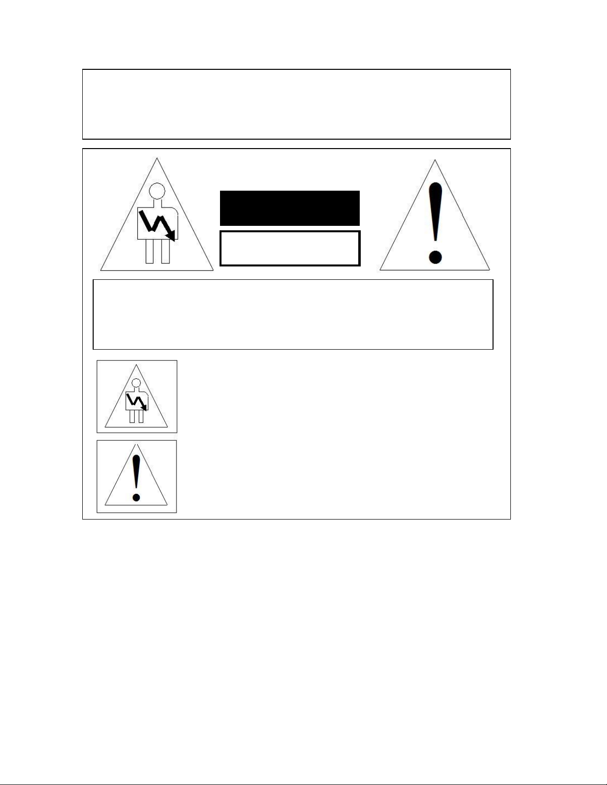
CAUTIONN
WARNING!!
To prevent fire or shock hazard, do not expose this appliance to rain or moisture
RISK OF ELECTRIC SHOCK
DO NOT OPEN
CAUTION: TO REDUCE THE RISK OF ELECTRIC SHOCK,
DO NOT REMOVE COVER (OR BACK).
NO USER-SERVICEABLE PARTS INSIDE.
REFER SEVICING TO QUALIFIED SERVICE PERSONNEL.
The lightning flash with the arrowhead symbol superimposed
across a graphical representation of a person, within an equilateral
triangle, is intended to alert the user to the presence of uninsulated
“dangerous voltage” within the product’s enclosure that may be of
sufficient magnitude to constitute a risk of electric shock.
The exclamation point within an equilateral triangle is intended to
alert the user to the presence of important operating and
maintenance (servicing) instructions in the literature
accompanying the appliance.
IMS.OM.002949.DRM Page 22 of 320 Version 1.7
Doremi Labs
Page 23

1 Introduction
1.1 Purpose
This manual is intended to demonstrate to the user how to install, operate, and use the software
on the IMS1000 Integrated Media Server.
1.2 Software Version
This manual is intended for use with software version 2.6.4 and higher.
This manual is intended for use with Web GUI version 1.1.7.
The SM Version is:
o 6.0.14 and higher for Series-2 Projectors.
1.3 Contact Technical Support
If in need of help or assistance, please contact Doremi Labs Technical Services:
USA
24/7 Technical Services line: + 1-866-484-4004
Technical Services Email: cinemasupport@doremilabs.com
Europe
24/7 Technical Services line: + 33 (0) 492-952-847
Technical Services Link: http://support.doremitechno.org/ticketing
Japan
Technical Services line: + 044-966-4855
Technical Services Email: support@doremilabs.co.jp
Australia ~ China ~ India ~ Indonesia ~ Korea ~ Malaysia ~ New Zealand ~ Philippines ~
Singapore ~ Taiwan ~ Thailand
Technical Services Email: supportasia@doremilabs.com
IMS.OM.002949.DRM Page 23 of 320 Version 1.7
Doremi Labs
Page 24

This page has been intentionally left blank.
IMS.OM.002949.DRM Page 24 of 320 Version 1.7
Doremi Labs
Page 25

2 ESD Rules
ESD Safety Rules
ESD (Electrostatic Discharge) safety rules are to be respected while installing, repairing, or
upgrading hardware on Doremi Cinema Servers.
The basic rules and elements of ESD control are the following:
Grounded personnel:
o All technicians must wear ESD safe smocks, wrist straps, and heel straps that
are properly attached.
o Never touch a sensitive component or assembly unless properly grounded.
Always assume that all electronic (solid-state) components and assemblies are sensitive
to ESD damage.
Always do the work on static safe work surfaces/work stations/desks. Make sure your
desk and wrist strap ground outlets are connected to the building ground.
Be aware of the static generating materials that you work with.
Always use grounded cards during loading/unloading of ESD devices.
Never transport, store, or handle sensitive components or assemblies except in a static-
safe environment (ESD static bags).
Always store ESD devices using safe tote boxes.
Personnel Training:
o Training courses should be required for all employees who handle or otherwise
come into contact with ESD items.
o The training program and the level of ESD protection should be tailored to the
needs and sensitivity of the product or production area.
o Recurrent training for personnel should be an integral part of the program.
IMS.OM.002949.DRM Page 25 of 320 Version 1.7
Doremi Labs
Page 26

This page has been intentionally left blank.
IMS.OM.002949.DRM Page 26 of 320 Version 1.7
Doremi Labs
Page 27

3 IMS1000 Overview
The IMS1000 is a state-of-the-art DCI compliant Integrated Media Server capable of playing
movies and trailer packages in MXF format at up to 500 Mbits/sec when installed into a DLP
Series-2 Projector.
The IMS1000 supports the highest JPEG2000 decoding formats including 4K, 12-bit 4:4:4, or
10-bit 4:2:2 for 2D and 3D HFR applications. The IMS1000 incorporates High-Definition
Multimedia Interface technology. The IMS1000 accepts alternative content through HDMI®
inputs and live stream. Movies and clips are stored on an on-board RAID5 storage.
The IMS1000 is controlled via Ethernet interface using a web based version of CineLister,
TMS2000, or third party theater management system supporting Doremi servers. Ingest is done
via USB, eSATA, or Ethernet.
3.1 IMS1000 Key Features and Functions
● Doremi designed and manufactured
● Single board solution (SMS and IMB on a single board)
● High quality storage
● Support for local storage
● HDMI input — 4K support is forthcoming, Q3 2014
● 3D Live (Sensio® Live & RealD® Live)
● RealD ghost busting®
● Auro 3D audio®
● Web based interface
● Support for access products (Fidelio & CaptiView)
● Ingest through eSATA, USB, or Ethernet
● Live Support (Ethernet stream, Mpeg2, H264, VC1 up to 50Mbits/s)
● Scaler and Deinterlacer included
● GPIOs (4in & 6out)
● SDI inputs support the following 3D mappings:
○ Dual Stream
○ Side by Side
○ Top Bottom
○ Sensio HiFi 3D — support is forthcoming, Q3 2014
○ RealD 3D — support is forthcoming, Q3 2014
3.1.1 JPEG2000 DCI DCP playback
Support 2K playback up to 120fps
Support 4K playback up to 60fps
Bitrates up to 500Mbits/s
DCI compliant
12Bits 4:4:4 XYZ’ for all formats
IMS.OM.002949.DRM Page 27 of 320 Version 1.7
Doremi Labs
Page 28

3.1.2 MPEG2/H264/VC1 MXF Interop:
720p 60 fps, 1080i, 1080p up to 30 fps
Bitrates up 50MBits/s
4:2:0, 8bits
3.1.3 Video processing features:
Color conversion support - YCbCr601, YCbCr709, RGB rec709, XYZ’ and YCxCz
De-Interlacing
Scaler (upscale up to 4K) - To be released, Q3 2014
3.1.4 Security
Doremi Forensic Watermarking for audio and video
FIPS 140-2 Level 3 Security certified
3.1.5 Audio
16 channels, AES-EBU, 24bits up to 96KHz
3.1.6 Alternative Content
HDMI input (See Annex D for the list of supported formats)
HDSDI (1.5 Gbit) Support
Dual 3GSDI— support is forthcoming, Q3 2014
Live content (network input)
Alternative audio routing (using HDMI audio, SDI embedded audio, and live input).
3.1.7 Pre-Loaded Test Content
Used for testing playback when hard drives are not installed. See Section 16.2 for more
information.
3.2 Input / Output Ports
2x Gigabit Ethernet (RJ45) (Eth0 is full speed, Eth1 is max 500mbit/s)
1x eSATA 3GBit/s
3x USB 2.0
1x HDMI input
2x 3GSDI bidirectional (input and output) — support is forthcoming, Q3 2014
8x AES pair (using 2x RJ45)
4x GPI ports (1x RJ45)
6x GPO ports (1x RJ45)
IMS.OM.002949.DRM Page 28 of 320 Version 1.7
Doremi Labs
Page 29
3.3 Environmental Specifications
Temperature Range (Ambient):
Operating: 10C to 40C or 50F to 104F
Non-operating: -20C to 60C or -4F to 140F
3.4 Performance / Storage / Power
The IMS1000 uses 3 x 1TB HDDs (2.5”), providing 2TB of media storage
Raid 5 storage is hardware based
The IMS1000 supports up to 4K 60fps and 2K HFR up to 120 fps
The IMS1000 supports 500 Mbits/s playback
Battery: IMS1000 battery is a Panasonic Vanadium rechargeable lithium battery VL3032.
Power < 70W (Power input 12V@6.25A from projector main LVDS connector)
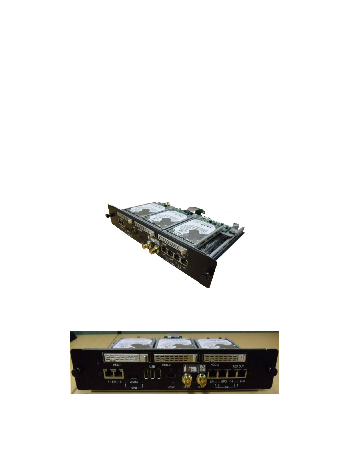
3.5 IMS1000
● An IMS1000 is shown below (Figure 1):
Figure 1: IMS1000
3.6 IMS1000 Faceplate Overview
Figure 2: IMS1000 with NEC Faceplate
IMS.OM.002949.DRM Page 29 of 320 Version 1.7
Doremi Labs
Page 30
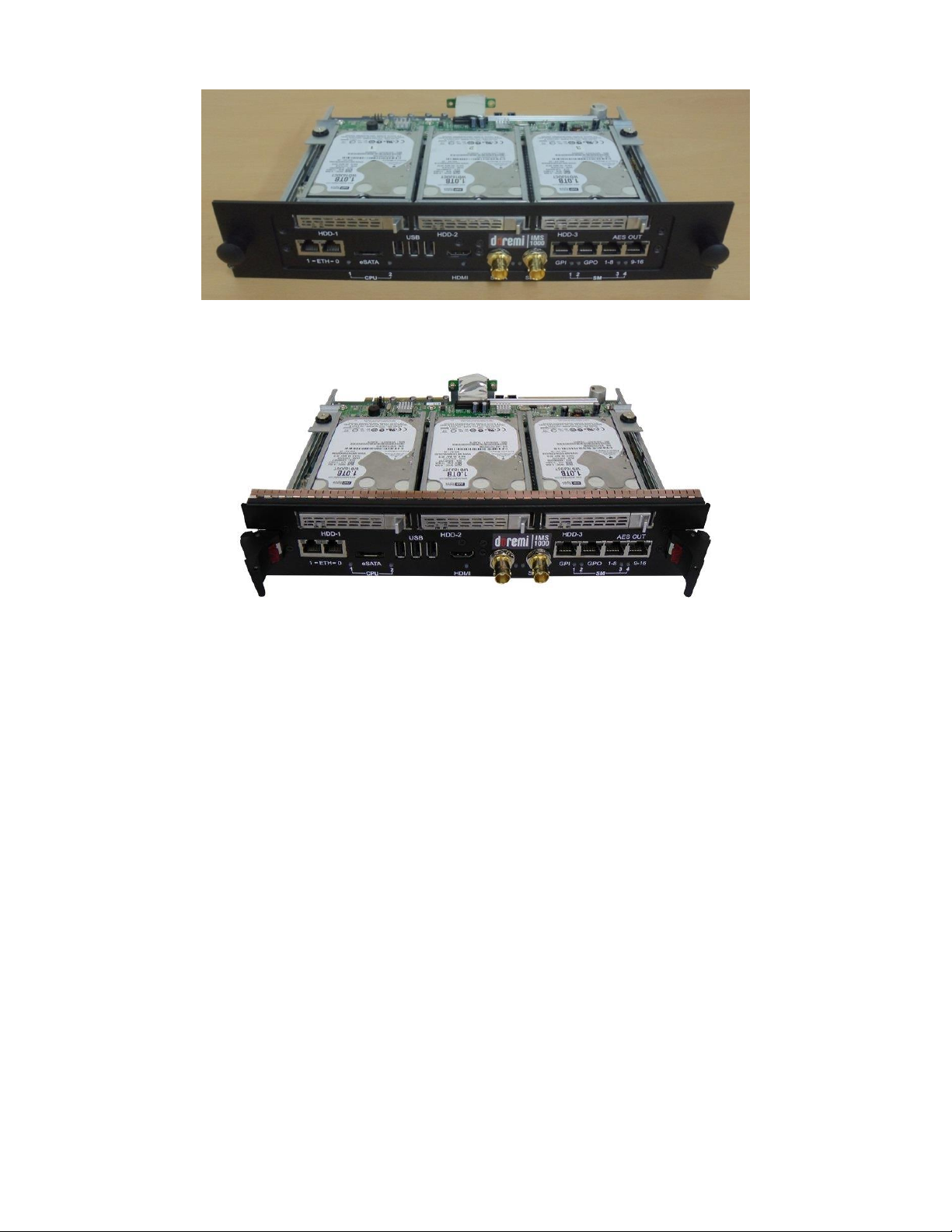
Figure 3: IMS1000 with Barco Faceplate
Figure 4: IMS1000 with Christie Faceplate
Ethernet
● The IMS1000 has two built-in Gigabit Ethernet connectors. The left one is identified as
ETH1 and the right one is identified as ETH0.
eSATA
● Used for ingesting content at four times the maximum transfer rate of USB 2.0.
USB
● There are three USB 2.0 ports on the front panel that can accommodate an external
USB device, such as the CaptiView transmitter or USB external drive for content
ingestion.
HDMI
To be used for inputting of alternative content, i.e., Blu-ray Disc player, Gaming, Digital
Cameras or Laptop presentations.
HDCP (High-bandwidth Digital Content Protection) supported
IMS.OM.002949.DRM Page 30 of 320 Version 1.7
Doremi Labs
Page 31

Pin #
Signal
1
GPI 0+
2
GPI 0-
3
GPI 1+
4
GPI 2+
5
GPI 2-
6
GPI 1-
7
GPI 3+
8
GPI 3-
Pin #
Signal
1
GPO 0
2
GPO 1
3
GPO 2
4
GPO 4
5
GPO 5
6
GPO 3
7
+5 VDC
8
Ground
Channels 1-8
Signal
1
Channel 1 & 2 plus
2
Channel 1 & 2 minus
3
Channel 3 & 4 plus
4
Channel 5 & 6 plus
5
Channel 5 & 6 minus
6
Channel 3 & 4 minus
7
Channel 7 & 8 plus
8
Channel 7 & 8 minus
SDI-A/SDI-B
● 3G-SDI — support is forthcoming, Q3 2014
● Used for Dual Projector setups
● Chase Mode
● Alternative Content Inputs
GPI
● General Purpose Input for Automation Interface
● RJ-45 Connector
GPO
● General Purpose Output for Automation Interface
● RJ-45 Connector
AES-OUT 1-8
● Digital Audio Channels 1 - 8 Output
● RJ-45 Connector
IMS.OM.002949.DRM Page 31 of 320 Version 1.7
Doremi Labs
Page 32

Channels 1-8
Signal
1
Channel 9 & 10 plus
2
Channel 9 & 10 minus
3
Channel 11 & 12 plus
4
Channel 13 & 14 plus
5
Channel 13 & 14 minus
6
Channel 11 & 12 minus
7
Channel 15 & 16 plus
8
Channel 15 & 16 minus
AES-OUT 9-16
● Digital Audio Channels 9-16 Output
● RJ-45 Connector
LEDs
See Figure 5 for LED placement.
For more information, please refer to Section 20.
IMS.OM.002949.DRM Page 32 of 320 Version 1.7
Doremi Labs
Figure 5: LED Diagram
Page 33

This page has been intentionally left blank.
IMS.OM.002949.DRM Page 33 of 320 Version 1.7
Doremi Labs
Page 34

Filter
Cover
4 Installation and Marriage with a NEC Series-2
Projector
Before you begin to install the IMS1000 into your projector, be sure that:
o The projector is powered down and in the off position.
o Disconnect the AC power cord from the wall.
o Remember to always follow ESD procedures.
4.1 Preparation
Figure 6: NEC Projector
Gently pull on the filter cover to remove it (Figure 7).
Figure 7: Remove Filter Cover
IMS.OM.002949.DRM Page 34 of 320 Version 1.7
Doremi Labs
Page 35

Screw
Screw
Screw
Screw
Key
Hole
Remove the four screws holding the projector cover in place (Figure 8).
Figure 8: Screw Locations
Using the key for the projector screen, turn the key in the lock to the right so that it is
unlocked (Figure 9).
Figure 9: Projector Unlock
Gently pull the cover off to remove it from the projector (Figure 10).
IMS.OM.002949.DRM Page 35 of 320 Version 1.7
Doremi Labs
Page 36

Two
Handles
Blank
Cover
Figure 10: Projector Cover Removed
Remove the blank cover of the media block slot by unscrewing the two handles at the
side (Figure 11).
Figure 11: Unscrewing the Slot Cover
The media block slot should now be empty (Figure 12).
IMS.OM.002949.DRM Page 36 of 320 Version 1.7
Doremi Labs
Page 37

Guiderails
Figure 12: Empty Slot
Carefully remove IMS1000 from its carton and antistatic bag.
Gently place the IMS1000 board into the projectors media block slot guiderails on the
inside of the slot (Figure 12 and Figure 13).
Figure 13: Missing HDDs
Screw in the handles on the side of the IMS1000 board to secure it in the projector
(Figure 14).
IMS.OM.002949.DRM Page 37 of 320 Version 1.7
Doremi Labs
Page 38

Two
Handles
Silver
Release
Lever
Figure 14: Securing the Board
4.2 HDDs
HDDs are to be shipped out of their chassis. Upon initial installation, insert them into the
IMS1000 HDDs chassis carrier prior to powering up the projector.
Do not insert or remove HDDs if the unit is powered on.
HDDs are to be of the same make and model and have the same capacity.
Doremi prohibits mixing SATA I drives with SATA II drives within the same RAID.
Each one of the three HDDs that come with the IMS1000 will be labeled with a 1, 2, or 3.
The HDD labeled 1 is to be inserted into the left hand HDD slot, labeled HDD-1, on the
IMS1000.
The HDD labeled 2 is to be inserted into the middle HDD slot, labeled HDD-2, on the
IMS1000.
The HDD labeled 3 is to be inserted into the right hand HDD slot, labeled HDD-3, on the
IMS1000.
Each HDD has a silver latch mechanism that allows for unlatching of the drive from the
hard drive cage (Figure 15).
Figure 15: Silver Latch on HDD
IMS.OM.002949.DRM Page 38 of 320 Version 1.7
Doremi Labs
Page 39

Spring Loaded
HDD Carrier
Handle
For each HDD, press on the silver release lever on the front side in order to release the
spring loaded HDD carrier handle (Figure 15).
With the carrier handle open, insert the drive all the way into the chassis cage (Figure
16).
Figure 16: HDD Insertion
Close the silver HDD carrier handle until you hear an audible click and the release tab
has locked the HDD into place.
Repeat for the other two HDDs.
The HDDs properly installed will look like the image presented below (Figure 17).
Figure 17: HDDs Inserted
IMS.OM.002949.DRM Page 39 of 320 Version 1.7
Doremi Labs
Page 40

4.3 Reattaching the Projector Covers
Reattach the projector cover and screw in the four screws holding it in place (Figure 18).
Figure 18: Reattaching the Projector Cover
Turn the key to lock the projector in place (Figure 19).
Figure 19: Turning the Lock
Reattach the filter cover by gently pushing it into place (Figure 20).
IMS.OM.002949.DRM Page 40 of 320 Version 1.7
Doremi Labs
Page 41

AES-OUT
1-8
AES-OUT
9-16
Figure 20: Reattaching the Filter Cover
4.4 Audio Cables Installation
Figure 21: Audio Connectors
● Plug one shielded CAT5 or CAT6 cable end into the connector labeled AES-OUT 1-8 on
the IMS1000 board (Figure 21).
● Plug the other end of the shielded CAT5 or CAT6 cable into the audio processor.
● Take another shielded CAT5 or CAT6 cable and plug the end into the connector labeled
AES-OUT 9-16 (Figure 21).
● Plug the other end of the shielded CAT5 or CAT6 cable into the audio processor.
Note: If the audio processor does not have RJ-45 connectors but has a single DB25 connector,
then you will need to use the RJ-45 to DB25 converter that is provided with the IMS1000 (Figure
22).
IMS.OM.002949.DRM Page 41 of 320 Version 1.7
Doremi Labs
Page 42

GPI
GPO
Figure 22: RJ-45 to DB25 Converter
4.5 GPI/GPO Cables Installation
Figure 23: GPI/GPO Connectors
● Plug one shielded CAT5 or CAT6 cable end into the connector labeled GPI on the
IMS1000 board (Figure 23). Install a ferrite core clamp near the connector closest to the
IMS1000. Refer to Section 25 for more information on ferrite core clamp installation.
● Plug the other end of the shielded CAT5 or CAT6 cable into whichever automation
controller is available or required.
● Take another shielded CAT5 or CAT6 cable and plug the end into the IMS1000
connector labeled GPO (Figure 23). Install a ferrite core clamp near the connector
closest to the IMS1000. Refer to Section 25 for more information on ferrite core clamp
installation.
● Plug the other end of the shielded CAT5 or CAT6 cable into whichever automation
controller is available or required.
IMS.OM.002949.DRM Page 42 of 320 Version 1.7
Doremi Labs
Page 43

Ethernet
Cable
4.5.1 GPI/GPO Pin-Out Information
Figure 24: RJ45 Socket Pin-Out
4.6 Ethernet Cables
● Connect an Ethernet cable to the Ethernet connector on the IMS1000 and the other end
of the cable to either a laptop or network switch (Figure 25). Install a ferrite core clamp
near the connector closest to the IMS1000. Refer to Section 25 for more information on
ferrite core clamp installation.
Figure 25: Ethernet Connector
Note: Ethernet port (Eth0) is set to DHCP by default. All IMS1000 boards are shipped
from the factory with the following default IP address for Eth1:
o IP: 192.168.100.50
o SM: 255.255.255.0
o GW: 192.168.100.1
For more information, refer to Section 23.
IMS.OM.002949.DRM Page 43 of 320 Version 1.7
Doremi Labs
Page 44

4.7 Power on Projector
● Connect AC power to the projector (Figure 26).
Figure 26: AC Power
● Turn the projector on. The expected boot up time is about 2:30 minutes (Figure 27).
Please refer to the projector manufacturer manual for proper power up sequence.
Figure 27: Power Switch
4.8 Accessing the GUI
● To access the IMS1000 GUI (Graphical User Interface), launch your browser on the
computer that is connected and enter the IP address into the browsers window.
You will be presented with the Doremi IMS1000 Login screen.
● Enter Username: doremi
● Enter Password: doremi
● Click the Login button.
IMS.OM.002949.DRM Page 44 of 320 Version 1.7
Doremi Labs
Page 45

New
Device
Button
4.9 Configuring the Device
In order for the projector to communicate with the IMS1000, the projector must be configured in
the Device Manager. While the projector is booting up, configure the device in the Device
Manager.
To access the Device Manager, go to Administration → Device Manager (Figure 28).
Figure 28: Device Manager
Select Projector from the New Device drop down menu (Figure 29).
IMS.OM.002949.DRM Page 45 of 320 Version 1.7
Doremi Labs
Page 46

Projector
Selected
Save
Button
Figure 29: Add Projector Drop-Down
Populate the projector parameters that appear (Figure 30).
Figure 30: Projector Added
Click the Save button (Figure 30).
IMS.OM.002949.DRM Page 46 of 320 Version 1.7
Doremi Labs
Page 47

Ok
Button
Mode
Button
4.10 Marriage
To perform the marriage, the user must download and install the latest version of the Digital
Cinema Communicator for S2 (DCC). If you do not have the latest version installed, contact
your administrator.
When first opened, the Communication Settings window will appear. Input the IP
address of the projector and click Ok (Figure 31).
Figure 31: Communication Settings
On the window that appears, click on the Mode button (Figure 32).
Figure 32: Mode Button
IMS.OM.002949.DRM Page 47 of 320 Version 1.7
Doremi Labs
Page 48

Setup
Button
Arrow
Button
Service
Button
In the Control Mode window that appears, select Service. Input the correct password
and click Ok. To obtain the password, contact your administrator (Figure 33).
Figure 33: Control Mode Window
Using the Arrow button in the window that appears, scroll until the Setup button is
available. Click on the Setup button (Figure 34).
Figure 34: Setup Button
When the Setup window appears, click on the Option Slot button (Figure 35).
IMS.OM.002949.DRM Page 48 of 320 Version 1.7
Doremi Labs
Page 49

Option
Slot
Button
Apply
Button
Figure 35: Setup Window
In the Option Slot window, select IMB from the drop-down and click Apply (Figure 36).
Figure 36: Option Slot Window
Click the Installation button and then click the Re-Marriage button (Figure 37).
IMS.OM.002949.DRM Page 49 of 320 Version 1.7
Doremi Labs
Page 50

Installation
Button
Re-Marriage
Button
Re-Marriage
Button
Ok
Button
Figure 37: Re-Marriage Button
Enter the appropriate password and login. Contact your administrator for the necessary
information. Click the Re-Marriage button (Figure 38).
Figure 38: Re-Marriage Login
A window will appear stating that the operation was successful. Click Ok (Figure 39).
Figure 39: Operation Successful Window
IMS.OM.002949.DRM Page 50 of 320 Version 1.7
Doremi Labs
Page 51

Enter
Button
Menu
Button
Security
Manager
Section
To arm the service door, push and hold the Menu button on the projector (Figure 40).
Enter the appropriate password and click Enter on the projector. Contact your
administrator for the password (Figure 40).
Figure 40: Projector Menu
To ensure that the marriage was completed correctly, on the IMS1000 GUI, go to Monitoring →
Diagnostics → Media Block. The Security Manager section should appear as it does below
(Figure 41):
Figure 41: Security Manager Section
Marriage has now been completed.
IMS.OM.002949.DRM Page 51 of 320 Version 1.7
Doremi Labs
Page 52

This page has been intentionally left blank.
IMS.OM.002949.DRM Page 52 of 320 Version 1.7
Doremi Labs
Page 53

5 Installation and Marriage with a Barco Series-2
Projector
Before you begin to install the IMS1000 into your projector, be sure that:
o The projector is powered down and in the off position.
o Disconnect the AC power cord from the wall.
o Remember to always follow ESD procedures.
5.1 Preparation
Figure 42: Barco Projector
Remove the blank cover of the media block slot by unscrewing the two screws on the
sides (Figure 43).
IMS.OM.002949.DRM Page 53 of 320 Version 1.7
Doremi Labs
Page 54

Two
Screws
Blank
Cover
Guiderails
Figure 43: Unscrewing the Blank Cover
The media block slot should now be empty (Figure 44).
Figure 44: Empty Media Block Slot
Carefully remove the IMS1000 from its carton and antistatic bag.
Gently place the IMS1000 board into the projectors media block slot guiderails on the
inside of the slot (Figure 44).
Tighten the two screws in place (Figure 45).
IMS.OM.002949.DRM Page 54 of 320 Version 1.7
Doremi Labs
Page 55

Silver
Release
Lever
Two
Screws
Figure 45: Tightening the Screws
5.2 HDDs
HDDs are to be shipped out of their chassis. Upon initial installation, insert them into the
IMS1000 HDDs chassis carrier prior to powering up the projector.
Do not insert or remove HDDs if the unit is powered on.
HDDs are to be of the same make and model and have the same capacity.
Doremi prohibits mixing SATA I drives with SATA II drives within the same RAID.
Each one of the three HDDs that come with the IMS1000 will be labeled with a 1, 2, or 3.
The HDD labeled 1 is to be inserted into the left hand HDD slot, labeled HDD-1, on the
IMS1000.
The HDD labeled 2 is to be inserted into the middle HDD slot, labeled HDD-2, on the
IMS1000.
The HDD labeled 3 is to be inserted into the right hand HDD slot, labeled HDD-3, on the
IMS1000.
Each HDD has a silver latch mechanism that allows for unlatching of the drive from the
hard drive cage (Figure 46).
Figure 46: Silver Latch on HDD
IMS.OM.002949.DRM Page 55 of 320 Version 1.7
Doremi Labs
Page 56

Spring Loaded
HDD Carrier
Handle
For each HDD, press on the silver release lever on the front side in order to release the
spring loaded HDD carrier handle (Figure 46).
With the carrier handle open, insert the drive all the way into the chassis cage (Figure
47).
Figure 47: HDD Insertion
Close the silver HDD carrier handle until you hear an audible click and the release tab
has locked the HDD into place.
Repeat for the other two HDDs.
The HDDs properly installed will look like the image presented below (Figure 48).
IMS.OM.002949.DRM Page 56 of 320 Version 1.7
Doremi Labs
Figure 48: HDDs Inserted
Page 57

AES-OUT
1-8
AES-OUT
9-16
5.3 Audio Cables Installation
Figure 49: Audio Connectors
● Plug one shielded CAT5 or CAT6 cable end into the connector labeled AES-OUT 1-8 on
the IMS1000 board (Figure 49).
● Plug the other end of the shielded CAT5 or CAT6 cable into the audio processor.
● Take another shielded CAT5 or CAT6 cable and plug the end into the connector labeled
AES-OUT 9-16 (Figure 49).
● Plug the other end of the shielded CAT5 or CAT6 cable into the audio processor.
Note: If the audio processor does not have RJ-45 connectors but has a single DB25 connector,
then you will need to use the RJ-45 to DB25 converter that is provided with the IMS1000 (Figure
50).
Figure 50: RJ-45 to DB25 Converter
IMS.OM.002949.DRM Page 57 of 320 Version 1.7
Doremi Labs
Page 58

GPI
GPO
5.4 GPI/GPO Cables Installation
Figure 51: GPI/GPO Connectors
● Plug one shielded CAT5 or CAT6 cable end into the connector labeled GPI on the
IMS1000 board (Figure 51). Install a ferrite core clamp near the connector closest to the
IMS1000. Refer to Section 2525 for more information on ferrite core clamp installation.
● Plug the other end of the shielded CAT5 or CAT6 cable into whichever automation
controller is available or required.
● Take another shielded CAT5 or CAT6 cable and plug the end into the IMS1000
connector labeled GPO (Figure 51). Install a ferrite core clamp near the connector
closest to the IMS1000. Refer to Section 25 for more information on ferrite core clamp
installation.
● Plug the other end of the shielded CAT5 or CAT6 cable into whichever automation
controller is available or required.
5.4.1 GPI/GPO Pin-Out Information
Figure 52: RJ45 Socket Pin-Out
IMS.OM.002949.DRM Page 58 of 320 Version 1.7
Doremi Labs
Page 59

LAN
Connector
LAN
Connector
Ethernet
Connector
Cinema
Controller
Slot
5.5 Ethernet Cables
Connect an Ethernet cable from the LAN connector on the Barco projector’s cinema
controller slot and the other end of the cable to either a laptop or network switch (Figure
53). Install a ferrite core clamp near the connector closest to the IMS1000. Refer to
Section 25 for more information on ferrite core clamp installation.
Figure 53: Ethernet Connections
Note: Ethernet port (Eth0) is set to DHCP by default. All IMS1000 boards are shipped
from the factory with the following default IP address for Eth1:
o IP: 192.168.100.50
o SM: 255.255.255.0
o GW: 192.168.100.1
Connect an Ethernet cable from the Ethernet connector on the IMS and the other end of
the cable to the LAN connector on the Barco projector’s cinema controller slot (Figure
54).
Figure 54: Ethernet Connections
IMS.OM.002949.DRM Page 59 of 320 Version 1.7
Doremi Labs
Page 60

For more information, refer to Section 23.
5.6 Power on Projector
● Connect AC power to the projector (Figure 55).
Figure 55: AC Power
● Turn the projector on. The expected boot up time is about a 2:30 minutes (Figure 56).
Please refer to the projector manufacturer manual for proper power up sequence.
Figure 56: Power Switch
5.7 Accessing the GUI
● To access the IMS1000 GUI (Graphical User Interface), launch your browser on the
computer that is connected and enter the IP address into the browsers window.
You will be presented with the Doremi IMS1000 Login screen.
● Enter Username: doremi
● Enter Password: doremi
● Click the Login button.
IMS.OM.002949.DRM Page 60 of 320 Version 1.7
Doremi Labs
Page 61

New
Device
Button
5.8 Configuring the Device
In order for the projector to communicate with the IMS1000, the projector must be configured in
the Device Manager. While the projector is booting up, configure the device in the Device
Manager.
To access the Device Manager, go to Administration → Device Manager (Figure 28).
Figure 57: Device Manager
Select Projector from the New Device drop down menu (Figure 29).
IMS.OM.002949.DRM Page 61 of 320 Version 1.7
Doremi Labs
Page 62

Projector
Selected
Save
Button
Figure 58: Add Projector Drop-Down
Populate the projector parameters that appear (Figure 30).
Figure 59: Projector Added
Click the Save button (Figure 30).
IMS.OM.002949.DRM Page 62 of 320 Version 1.7
Doremi Labs
Page 63

Key
Button
5.9 Marriage
Marriage on the Barco projector is done directly on the projector. Once the projector has
finished booting up, the taillights at the back of the projector will be red, indicating that the board
and the projector are not married. If there is a touch screen attached to the projector, two
tamper errors will appear, indicating that the marriage has not occurred (Figure 60).
Important: When a new board will be used, the projector must be rebooted prior to beginning
the marriage process below in order for the marriage to be successful.
Figure 60: Tamper Errors
Reboot the projector.
To begin the marriage process, push the Key button. It should be red to indicate that the
marriage has not been completed (Figure 61).
Figure 61: Red Key Button
After you push the Key button, the numbered buttons should flash orange.
IMS.OM.002949.DRM Page 63 of 320 Version 1.7
Doremi Labs
Page 64

Key
Button
Security
Manager
Section
Enter in the correct password. Contact your administrator for the correct password.
The numbered buttons should flash green if you have entered the password correctly.
Allow about a minute for the tamper errors to clear.
Once the marriage has been completed, the Key button will turn green (Figure 62) and
the taillight will also turn green.
Figure 62: Green Key Button
To ensure that the marriage was completed correctly, on the IMS1000 GUI, go to Monitoring →
Diagnostics → Media Block. The Security Manager section should appear as it does below
(Figure 63):
Figure 63: Security Manager Section
Marriage is now complete.
IMS.OM.002949.DRM Page 64 of 320 Version 1.7
Doremi Labs
Page 65

This page has been intentionally left blank.
IMS.OM.002949.DRM Page 65 of 320 Version 1.7
Doremi Labs
Page 66

Two
Latches
6 Installation and Marriage with a Christie Series-2
Projector
Before you begin to install the IMS1000 into your projector, be sure that:
o The projector is powered down and in the off position.
o Disconnect the AC power cord from the wall.
o Remember to always follow ESD procedures.
6.1 Preparation
Figure 64: Christie Projector
Remove the blank cover of the media block slot, if it is present, by unlatching the two
latches on the sides (Figure 65).
Figure 65: Faceplate Latches
The media block slot should now be empty (Figure 66).
IMS.OM.002949.DRM Page 66 of 320 Version 1.7
Doremi Labs
Page 67

Guiderails
Red
Button
Figure 66: Empty Media Block Slot
Carefully remove the IMS1000 from its carton and antistatic bag.
Gently place the IMS1000 board into the projectors media block slot guiderails on the
inside of the slot (Figure 66). The latches must be out and open for the IMS1000 to fit
properly. To open the latches, press on the red button (Figure 67).
Figure 67: Red Button on Latch
Close the two latches to secure the board (Figure 68).
IMS.OM.002949.DRM Page 67 of 320 Version 1.7
Doremi Labs
Page 68

Two
Latches
Figure 68: IMS100 Installation
6.2 HDDs
HDDs are to be shipped out of their chassis. Upon initial installation, insert them into the
IMS1000 HDDs chassis carrier prior to powering up the projector.
Do not insert or remove HDDs if the unit is powered on.
HDDs are to be of the same make and model and have the same capacity.
Doremi prohibits mixing SATA I drives with SATA II drives within the same RAID.
Each one of the three HDDs that come with the IMS1000 will be labeled with a 1, 2, or 3.
The HDD labeled 1 is to be inserted into the left hand HDD slot, labeled HDD-1, on the
IMS1000.
The HDD labeled 2 is to be inserted into the middle HDD slot, labeled HDD-2, on the
IMS1000.
The HDD labeled 3 is to be inserted into the right hand HDD slot, labeled HDD-3, on the
IMS1000.
Each HDD has a silver latch mechanism that allows for unlatching of the drive from the
hard drive cage (Figure 69).
IMS.OM.002949.DRM Page 68 of 320 Version 1.7
Doremi Labs
Page 69

Silver
Release
Lever
Spring Loaded
HDD Carrier
Handle
Figure 69: Silver Latch on HDD
For each HDD, press on the silver release lever on the front side in order to release the
spring loaded HDD carrier handle (Figure 69).
With the carrier handle open, insert the drive all the way into the chassis cage (Figure
70).
The HDDs properly installed will look like the image presented below (Figure 71).
IMS.OM.002949.DRM Page 69 of 320 Version 1.7
Doremi Labs
Figure 70: HDD Insertion
Close the silver HDD carrier handle until you hear an audible click and the release tab
has locked the HDD into place.
Repeat for the other two HDDs.
Page 70

AES-OUT
1-8
AES-OUT
9-16
Figure 71: HDDs Inserted
6.3 Audio Cables Installation
Figure 72: Audio Connectors
● Plug one shielded CAT5 or CAT6 cable end into the connector labeled AES-OUT 1-8 on
the IMS1000 board (Figure 72).
● Plug the other end of the shielded CAT5 or CAT6 cable into the audio processor.
IMS.OM.002949.DRM Page 70 of 320 Version 1.7
Doremi Labs
Page 71

GPI
GPO
● Take another shielded CAT5 or CAT6 cable and plug the end into the connector labeled
AES-OUT 9-16 (Figure 72).
● Plug the other end of the shielded CAT5 or CAT6 cable into the audio processor.
Note: If the audio processor does not have RJ-45 connectors but has a single DB25 connector,
then you will need to use the RJ-45 to DB25 converter that is provided with the IMS1000 (Figure
73).
Figure 73: RJ-45 to DB25 Converter
6.4 GPI/GPO Cables Installation
Figure 74: GPI/GPO Connectors
● Plug one shielded CAT5 or CAT6 cable end into the connector labeled GPI on the
IMS1000 board (Figure 74). Install a ferrite core clamp near the connector closest to the
IMS1000. Refer to Section 25 for more information on ferrite core clamp installation.
● Plug the other end of the shielded CAT5 or CAT6 cable into whichever automation
controller is available or required.
IMS.OM.002949.DRM Page 71 of 320 Version 1.7
Doremi Labs
Page 72

Ethernet
Connection
● Take another shielded CAT5 or CAT6 cable and plug the end into the IMS1000
connector labeled GPO (Figure 74). Install a ferrite core clamp near the connector
closest to the IMS1000. Refer to Section 25 for more information on ferrite core clamp
installation.
● Plug the other end of the shielded CAT5 or CAT6 cable into whichever automation
controller is available or required.
6.4.1 GPI/GPO Pin-Out Information
Figure 75: RJ45 Socket Pin-Out
6.5 Ethernet Cables
Connect an Ethernet cable to the Ethernet connector on the IMS1000 and the other end
of the cable to either a laptop or network switch (Figure 76). Install a ferrite core clamp
near the connector closest to the IMS1000. Refer to Section 25 for more information on
ferrite core clamp installation.
Figure 76: Ethernet Connection
IMS.OM.002949.DRM Page 72 of 320 Version 1.7
Doremi Labs
Page 73

Login
Note: Ethernet port (Eth0) is set to DHCP by default. All IMS1000 boards are shipped
from the factory with the following default IP address for Eth1:
o IP: 192.168.100.50
o SM: 255.255.255.0
o GW: 192.168.100.1
For more information, refer to Section 23.
6.6 Power on Projector
● Connect AC power to the projector (Figure 77).
Figure 77: AC Power
After about 1:45 minutes, the main screen will appear on the touch panel controller. Go
to Menu → Login and login as Marriage. Contact your administrator for the correct
password (Figure 78).
Figure 78: Login
IMS.OM.002949.DRM Page 73 of 320 Version 1.7
Doremi Labs
Page 74

Content
Devices
Configuration
Administrator
Setup
Doremi
Selected
● Go to Menu → Administrator Setup → Content Devices Configuration (Figure 79). From
the drop-down menu, make sure that Doremi is selected (Figure 80).
Figure 79: Content Devices Configuration
Figure 80: Drop-Down Menu
● Turn the projector on by pressing the green Power button on the touch panel controller
(Figure 81). After about two minutes, the projector will be fully powered on.
IMS.OM.002949.DRM Page 74 of 320 Version 1.7
Doremi Labs
Page 75

Power
Button
Acknowledge
Button
Figure 81: Power Button
● An error message will appear. Press the Acknowledge button (Figure 82).
Figure 82: Error Message
6.7 Accessing the GUI
● After about forty more seconds, the board will be fully powered on and the user will be
able to access the web GUI. To access the IMS1000 GUI (Graphical User Interface),
launch your browser on the computer that is connected and enter the IP address into the
browsers window.
IMS.OM.002949.DRM Page 75 of 320 Version 1.7
Doremi Labs
Page 76

New
Device
Button
You will be presented with the Doremi IMS1000 Login screen.
● Enter Username: doremi
● Enter Password: doremi
● Click the Login button.
6.8 Configuring the Device
In order for the projector to communicate with the IMS1000, the projector must be configured in
the Device Manager. When the projector and board have finished booting up, configure the
device in the Device Manager.
To access the Device Manager, go to Administration → Device Manager (Figure 83).
Figure 83: Device Manager
Select Projector from the New Device drop-down menu (Figure 84).
IMS.OM.002949.DRM Page 76 of 320 Version 1.7
Doremi Labs
Page 77

Projector
Selected
Save
Button
Figure 84: Add Projector Drop-Down
Populate the projector parameters that appear (Figure 85).
Figure 85: Projector Added
Click the Save button (Figure 85).
IMS.OM.002949.DRM Page 77 of 320 Version 1.7
Doremi Labs
Page 78

IMB
Marriage
Acknowledge
Button
6.9 Marriage
Once the projector and board have finished booting up, the lights on the side of the projector will
be red and green, indicating that the board and the projector are not married. The touch panel
controller attached to the projector will show a second error window, indicating that the marriage
has not occurred (Figure 86). Press the Acknowledge button.
Figure 86: Error Window
Go to Menu → Service Setup → IMB Marriage (Figure 87).
Figure 87: IMB Marriage
The marriage wizard, on the touch panel controller, will then guide you through the steps
necessary to complete the marriage. Click the Next button to begin (Figure 88).
IMS.OM.002949.DRM Page 78 of 320 Version 1.7
Doremi Labs
Page 79

Next
Button
Next
Button
Figure 88: Marriage Wizard
When the Marriage Checklist window appears, click Next (Figure 89).
Figure 89: Marriage Checklist
IMS.OM.002949.DRM Page 79 of 320 Version 1.7
Doremi Labs
Page 80

Arm
Marriage
Button
Marriage
Button
The Arm Marriage window will appear. When the Arm Marriage button is pressed, the
user has 30 seconds to press the Marriage button on the projector, which should now be
green (Figure 90 and Figure 91).
Figure 90: Arm Marriage Window
Figure 91: Marriage Button on Projector
Once the marriage is complete, the light on the projector will turn green (Figure 92).
IMS.OM.002949.DRM Page 80 of 320 Version 1.7
Doremi Labs
Page 81

Security
Manager
Section
Figure 92: Green Projector Light
To ensure that the marriage was completed correctly, on the IMS1000 GUI, go to Monitoring →
Diagnostics → Media Block. The Security Manager section should appear as it does below
(Figure 93):
Figure 93: Security Manager Section
Marriage is now complete.
IMS.OM.002949.DRM Page 81 of 320 Version 1.7
Doremi Labs
Page 82

This page has been intentionally left blank.
IMS.OM.002949.DRM Page 82 of 320 Version 1.7
Doremi Labs
Page 83

Shutdown
Button
7 Shut Down
In order to properly shutdown the IMS1000 board and the projector, the user must follow the
steps below.
To shut down the board, go to Administration → System (Figure 94).
Figure 94: Shut Down
Click on the Shutdown button and wait two minutes. The LED lights on the IMS1000 will
stop flashing and the HDD lights will have a steady light once it has finished shutting
down.
After two minutes, refer to the projector manufacturer manual for proper power down
sequence to shut down the projector.
The IMS1000 board and the projector have now been properly shut down.
Warning: The IMS1000 must be shut down according to the designated method. Failure to
follow the above method may result in file corruption.
IMS.OM.002949.DRM Page 83 of 320 Version 1.7
Doremi Labs
Page 84

This page has been intentionally left blank.
IMS.OM.002949.DRM Page 84 of 320 Version 1.7
Doremi Labs
Page 85

Overview
Tab
8 Operating System
Every time the user logs out of the operating system and then logs back in, a Login
Authentication window will appear (Figure 95). The default login name is “doremi” and the
password is “doremi.” However, the administrator may have changed and/or added other login
usernames and passwords. Please contact your administrator for the appropriate information.
Figure 95: Login Authentication Window
● The Overview Tab will appear every time the unit is turned on or rebooted. Users can
access various applications from the tabs located across the top of the GUI (Figure 96).
Figure 96: Overview Tab Screen
IMS.OM.002949.DRM Page 85 of 320 Version 1.7
Doremi Labs
Page 86

8.1 Users
The user will be prompted to enter a password for various tasks when using different
applications. The administrator determines the level of security.
Note: Please contact your system administrator for passwords, not Doremi Labs.
The following are types of passwords/privileges the user may be asked for (Figure 97):
● Admin (Administrator) – Super User
● Manager – ShowManager
● Root – Administrator
● Ingest – Projection
● Doremi – Projection
Figure 97: Password Confirmation Window
In Figure 97, the user is asked to select the username and password.
Note: The server will need authentication to complete certain tasks. For example, the
authentication required in the window above is ShowManager privileges; hence the server will
automatically prompt the user to the Manager username. However, it is possible to select a
different username from the drop-down list as shown in Figure 97 above, depending on the level
of security that has been provided.
IMS.OM.002949.DRM Page 86 of 320 Version 1.7
Doremi Labs
Page 87

This page has been intentionally left blank.
IMS.OM.002949.DRM Page 87 of 320 Version 1.7
Doremi Labs
Page 88

Revert
Button
Save
Button
9 Network Configuration
9.1 Default Network Configuration
Ethernet port (Eth0) is set to DHCP by default. All IMS1000 boards are shipped from the factory
with the following default IP address for Eth1:
IP: 192.168.100.50
SM: 255.255.255.0
GW: 192.168.100.1
9.2 Changing the IP Address
To change the IP address of the server, go to the Administration Tab → Control Panel →
Networking Configuration and then follow the steps below (Figure 98):
Figure 98: Networking Configuration Window
● The Networking Configuration window will appear. You will need to populate the
following fields:
○ Hostname
■ Note: It is a good idea to input the circuit location/screen number in here.
For example, “DoremiScreen-1,” as it will be easier to identify in the logs.
○ Properties of both eth0 & eth1:
■ IP Address
● Note: Do not put leading zeroes (0) in front of any numbers. For
example, do not input 192.168.100.050.
■ Netmask
■ Gateway
IMS.OM.002949.DRM Page 88 of 320 Version 1.7
Doremi Labs
Page 89

IP
Address
Confirmed
Monitoring
Tab
Note: You can use the tick box for either of these to obtain an IP address automatically with
DHCP.
● Select the Save button to keep these settings.
● You will be prompted to key in a password to keep these settings. See your system
administrator for this password. SuperUser privileges are necessary to be able to
confirm the changes. If the user is already logged in with SuperUser privileges, a
password window will not appear.
● To verify the setup, go to Monitoring Tab → Diagnostics → System → Networking and
verify the IP Address listed in the area labeled Networking (Figure 99).
Figure 99: System Monitoring Tab Window
IMS.OM.002949.DRM Page 89 of 320 Version 1.7
Doremi Labs
Page 90

Revert
Button
Administration
Tab
9.3 Network Reset
If for any reason the network settings need to be reset, go to Administration → Control Panel →
Networking Configuration and click the Revert button located on the bottom of the screen
(Figure 100).
Figure 100: Networking Configuration Window
IMS.OM.002949.DRM Page 90 of 320 Version 1.7
Doremi Labs
Page 91

10 Time Zone Configuration
Units are by default set to Pacific Time Zone (PST or PDT). This section provides information on
how to check and/or change the time zone.
10.1 Checking the Time Zone
● To check the time and time zone, go to Administration → Control Panel → Time Settings
and the Date and Time tab will appear (Figure 101).
Figure 101: Current Date and Time Window
IMS.OM.002949.DRM Page 91 of 320 Version 1.7
Doremi Labs
Page 92

Update
Button
10.2 Changing the Time Zone
To change the time zone, follow the steps bellow:
● Go to Administration → Control Panel → Time Settings and the Date and Time tab will
appear.
● Click on the drop-down menu labeled, Timezone.
● A list of time zones will appear (Figure 102).
Figure 102: TimeZone Drop-Down Window
● Select the time zone that best represents the geographical area in which the IMS1000 is
installed.
● Once the appropriate timezone has been selected and appears within the box labeled
Timezone, click the Update button to save this setting (Figure 102).
● SuperUser privileges are necessary to save the change.
● Reboot for the changes to take effect.
10.3 Changing the System Time
To modify the IMS1000 system clock (RTC - Real Time Clock), follow the steps below:
Note: DCI specification allows the user to only modify the time +/- up to 6 minutes per calendar
year.
● Go to Administration → Control Panel → Time Settings and the Date and Time tab will
appear.
● Click on one of the appropriate drop-downs to modify minutes or seconds.
IMS.OM.002949.DRM Page 92 of 320 Version 1.7
Doremi Labs
Page 93

Update
Button
NTP
Servers
Tab
● For each box, a list of time settings will appear (Figure 103).
Figure 103: Change Time Drop-Down Window
● Once the appropriate time change has been selected and appears within the box
labeled, Change Time, click the Update button to save this setting (Figure 103).
● SuperUser privileges are necessary to save the change.
● If you exceed your allotted +/- 6 minute limit, contact your first tier support
representative.
IMS.OM.002949.DRM Page 93 of 320 Version 1.7
Doremi Labs
Page 94

Add
Button
10.4 NTP Servers
NTP (Network Time Protocol) Servers are specific servers that sync the time and date on your
unit to the UTC time. To access the NTP Servers tab, click on the green arrow button on the
right side of the Date and Time tab, found by going to Administration → Control Panel → Time
Settings (Figure 103). Click the Add button to add your NTP server (Figure 104).
Figure 104: NTP Servers
IMS.OM.002949.DRM Page 94 of 320 Version 1.7
Doremi Labs
Page 95

This page has been intentionally left blank.
IMS.OM.002949.DRM Page 95 of 320 Version 1.7
Doremi Labs
Page 96

Notification
Bar
Top
Tabs
Bar
11 Overview Tab
The Overview Tab will always display first upon logging in to the IMS1000 GUI (Figure 105).
This tab provides the user with a snap shot of the systems current status. The top section of the
screen, labeled Playback Status, will display the current playback status along with any
upcoming ShowPlaylist schedules.
The lower part of this screen displays the current system status and is separated by storage,
server, and projector status. Hot links on this tab provide quick access to the user for its
respective function.
From the top Tabs Bar, the user can navigate to the Administration Tab, Control Tab, or the
Monitoring Tab.
Figure 105: Overview Tab
11.1 Notification Bar
The bottom Notification Bar allows the user to quickly access important features of the
IMS1000. These buttons are available and can be accessed at the bottom of every tab.
11.1.1 Quick Controls
The Quick Controls button allows quick access to macros that have been added in the Quick
Controls tab, located at Administration → Macro Editor → Quick Controls. It allows the user to
execute a macro from any tab on the GUI. For information on how to add macros to the Quick
Controls tab, refer to Section 12.7.
IMS.OM.002949.DRM Page 96 of 320 Version 1.7
Doremi Labs
Page 97

Quick
Controls
Button
Macros
Once the macros have been added, click on the Quick Controls button and the macros will
appear (Figure 106).
Figure 106: Quick Controls
To execute the macro, simply click on the macro (Figure 106).
Clicking on the Quick Controls button again will cause the window to close.
11.1.2 Playback
The Playback button will alert the user to any playback that is in progress (Figure 107).
If playback is in progress, clicking on the Playback button will open up the Cinelister Playback
tab. If playback is not in progress, clicking on the button will open up the Cinelister Editor tab.
For more information on the Cinelister tab and playback, refer to Section 13.
IMS.OM.002949.DRM Page 97 of 320 Version 1.7
Doremi Labs
Page 98

Ingest
Button
Playback
Button
Figure 107: Playback Button
11.1.3 Ingest
The Ingest button will alert the user to any ingest that is in progress.
Clicking on the button will open the Ingest Monitor tab that displays the ingest progress (Figure
108). For more information on ingesting, refer to Section 13.9.
Figure 108: Ingest Monitor and Button
IMS.OM.002949.DRM Page 98 of 320 Version 1.7
Doremi Labs
Page 99

Session
Viewer
Button
11.1.4 Session Viewer
The Session Viewer button displays all of the users that are currently logged onto the unit.
Click the button to open the Session Viewer window. Clicking on the button again will cause the
window to close (Figure 109).
Figure 109: Session Viewer Window
11.1.5 Notifications
The Notifications button provides the user with notifications for things such as raid status, NTP
status, updates, software integrity, disk space quota, and more. A number will appear in the
corner when there is a new notification.
IMS.OM.002949.DRM Page 99 of 320 Version 1.7
Doremi Labs
Page 100

Notifications
Button
Delete
Button
Clear
All
Button
More
Details
Button
Figure 110: Notifications Window
Click on the Notifications button to view the notifications (Figure 110).
Clicking on the Notifications button again will cause the window to close.
Hovering over the More Details button provides more details about the notification
(Figure 110).
To delete a notification, highlight it and click on the X that appears on the right-hand side
(Figure 110). To delete all notifications, click on the X in the upper right corner of the
window.
IMS.OM.002949.DRM Page 100 of 320 Version 1.7
Doremi Labs
 Loading...