

Page 1

D S V - J 2
Field Installer Manual
Version 1.3
The English version of this document is the only legally binding version.
Translated versions are not legally binding and are for convenience only.
DSV.OM.000391.DRM Page 1 of 68 Version 1.3
Doremi Labs
Page 2

Table of Contents
1 Introduction............................................................................................................................. 7
2 Caution.................................................................................................................................... 8
3 DSV-J2 Presentation............................................................................................................. 10
4 Rear Panel Connectors......................................................................................................... 13
5 DSV-J2 IP Address................................................................................................................ 21
6 Device Manager Configuration............................................................................................ 23
7 Automation Set Up: Macro Editor Usage............................................................................ 27
8 Time Zone Set Up.................................................................................................................. 37
9 Vendor Specific Projector Set Up Instructions...................................................................38
10 DSV-J2 Software/Firmware USB Upgrade Instructions..................................................41
11 DSV-J2 Linux Terminal Commands...................................................................................43
12 Troubleshooting.................................................................................................................. 49
13 Appendix A: General Purpose Output Connection Diagram .........................................52
14 Appendix B: General Purpose Input Connection Diagram..............................................53
15 Appendix C: XML Structure Used by Macro Editor..........................................................54
16 Acronyms........................................................................................................................... 67
17 Document Revision History.............................................................................................. 68
DSV.OM.000391.DRM Page 2 of 68 Version 1.3
Doremi Labs
Page 3

Software License Agreement
The software license agreement can be found at the following location:
http://www.doremilabs.com/support/cinema-support/cinema-warranties/
Hardware Warranty
The hardware warranty can be found at the following location:
http://www.doremilabs.com/support/cinema-support/cinema-warranties/
DSV.OM.000391.DRM Page 3 of 68 Version 1.3
Doremi Labs
Page 4

WARNING!!
THIS DEVICE MUST BE GROUNDED.
IMPORTANT
Power requirements for electrical equipment vary from area to area. Please ensure that your
DSV-J2 meets the power requirements in your area. If in doubt, consult a qualified electrician or
your Doremi Labs dealer.
DSV-J2 Power Ratings
AC Input: 100-240V~, 6-3A, 60-50Hz
Maximum Power Consumption: 300W
WARNING: MULTIPLE SOURCES OF SUPPLY; DISCONNECT ALL SOURCES BEFORE
SERVICING.
DSV-J2 Rack Mount and Thermal Information
Maximum operating ambient temperature is 35°C.
Never restrict the air flow through the devices’ fan or vents.
When installing equipment into a rack, distribute the units evenly. Otherwise hazardous
conditions may be created by an uneven weight distribution.
Connect the unit only to a properly rated supply circuit. Reliable earthing (grounding) of
rack-mounted equipment should be maintained
PROTECTING YOURSELF AND THE DSV-J2
Never touch the AC plug with wet hands.
Always disconnect the DSV-J2 from the power supply by pulling on the plug, not the cord.
Allow only a Doremi Labs dealer or qualified professional engineer to repair or reassemble the
DSV-J2. Apart from voiding the warranty, unauthorized engineers might touch live internal parts
and receive a serious electric shock.
Do not put, or allow anyone to put, any object, especially metal objects into the DSV-J2.
Use only an AC power supply. Never use a DC power supply.
If water or any other liquid is spilled into or onto the DSV-J2, disconnect the power and call your
Doremi dealer.
Make sure the unit is well ventilated and away from direct sunlight. To avoid damage to internal
circuitry, as well as the external finish, keep the DSV-J2 away from sources of direct heat
(heater vents, stoves, radiators, etc.)
Avoid using flammable aerosols, etc. near the DSV-J2. They may damage the surface and may
ignite. Do not use denatured alcohol, paint thinner, or similar chemicals to clean the DSV-J2.
They will damage the finish.
Modification of this equipment is dangerous and can result in the functions of the DSV-J2 being
impaired. Never attempt to modify the equipment in any way.
DSV.OM.000391.DRM Page 4 of 68 Version 1.3
Doremi Labs
Page 5

In order to ensure optimum performance of your DSV-J2, select the setup location carefully and
make sure the equipment is used properly. Avoid setting up the DSV-J2 in the following
locations:
1. In a humid or dusty environment.
2. In a room with poor ventilation.
3. On a surface which is not level.
4. Inside a moving vehicle where it will be subject to vibration.
5. In an extremely hot or cold environment.
Removable Drives Warning
Removal of the hot swappable hard drives allows access to pins and traces supplying power to
the hard drive backplane. These are considered energy hazards.
REMOVAL OF HARD DRIVES MAY ONLY BE PERFORMED BY TRAINED SERVICE
PERSONNEL.
With regards to the energy hazard warning and removable drives, the equipment may only be
used in a restricted access location (not accessible to the general public).
CAUTION
Battery is located on the motherboard.
Danger of explosion if battery is incorrectly replaced.
Replace only with the same or equivalent type
recommended by the manufacturer.
Dispose of used batteries according
to the manufacturer’s instructions.
DSV.OM.000391.DRM Page 5 of 68 Version 1.3
Doremi Labs
Page 6
C A U T I O N
R I S K O F E L E C T R I C S H O C K
D O N O T O P E N
!
C A U T I O N : T O R E D U C E T H E R I S K O F E L E C T R I C S H O C K ,
D O N O T R E M O V E C O V E R ( O R B A C K ) .
N O U S E R - S E R V I C E A B L E P A R T S I N S I D E .
R E F E R S E R V I C I N G T O Q U A L I F I E D S E R V I C E P E R S O N N E L .
T h e l i g h t n i n g f l a s h w i t h t h e a r r o w h e a d s y m b o l s u p e r i m p o s e d
a c r o s s a g r a p h i c a l r e p r e s e n t a t i o n o f a p e r s o n , w i t h i n a n e q u i l a t e r a l
t r i a n g l e , i s i n t e n d e d t o a l e r t t h e u s e r t o t h e p r e s e n c e o f u n i n s u l a t e d
“ d a n g e r o u s v o l t a g e ” w i t h i n t h e p r o d u c t ’ s e n c l o s u r e ; t h a t m a y b e
o f s u f f i c i e n t m a g n i t u d e t o c o n s t i t u t e a r i s k o f e l e c t r i c s h o c k .
!
T h e e x c l a m a t i o n p o i n t w i t h i n a n e q u i l a t e r a l t r i a n g l e i s i n t e n d e d t o
a l e r t t h e u s e r t o t h e p r e s e n c e o f i m p o r t a n t o p e r a t i n g a n d
m a i n t e n a n c e ( s e r v i c i n g ) i n s t r u c t i o n s i n t h e l i t e r a t u r e
a c c o m p a n y i n g t h e a p p l i a n c e .
W A R N I N G ! !
T o p r e v e n t f i r e o r s h o c k h a z a r d , d o n o t e x p o s e t h i s a p p l i a n c e t o r a i n o r m o i s t u r e
DSV.OM.000391.DRM Page 6 of 68 Version 1.3
Doremi Labs
Page 7

1 Introduction
1.1 Purpose
This manual is designed to guide you through the setup and installation of the DSV-J2. It
provides information about the following steps:
Physical connections
DSV-J2 IP address setup
Projector(s) setup
Automation setup
Time zone setup
These steps correspond to Sections 3 through 8.
1.2 Contact Information
If in need of help or assistance, please contact Doremi Labs Technical Services:
USA
24/7 Technical Services line: + 1-866-484-4004
Technical Services Email: cinemasupport@doremilabs.com
Europe
24/7 Technical Services line: + 33 (0) 492-952-847
Technical Services Link: http://support.doremitechno.org/ticketing
Japan
Technical Services line: + 044-966-4855
Technical Services Email: support@doremilabs.co.jp
Australia ~ China ~ India ~ Indonesia ~ Korea ~ Malaysia ~ New Zealand ~ Philippines ~
Singapore ~ Taiwan ~ Thailand
Technical Services Email: supportasia@doremilabs.com
DSV.OM.000391.DRM Page 7 of 68 Version 1.3
Doremi Labs
Page 8

2 Caution
Blue button
Grey handle
2.1 Drives Insertion
2.1.1 General Rule
Do not insert drives if the unit is powered on.
2.1.2 HDDs Shipment
Drives (HDDs) might be shipped out of the chassis. If this is the case, insert them before
plugging in the power cables, according to the procedure presented below:
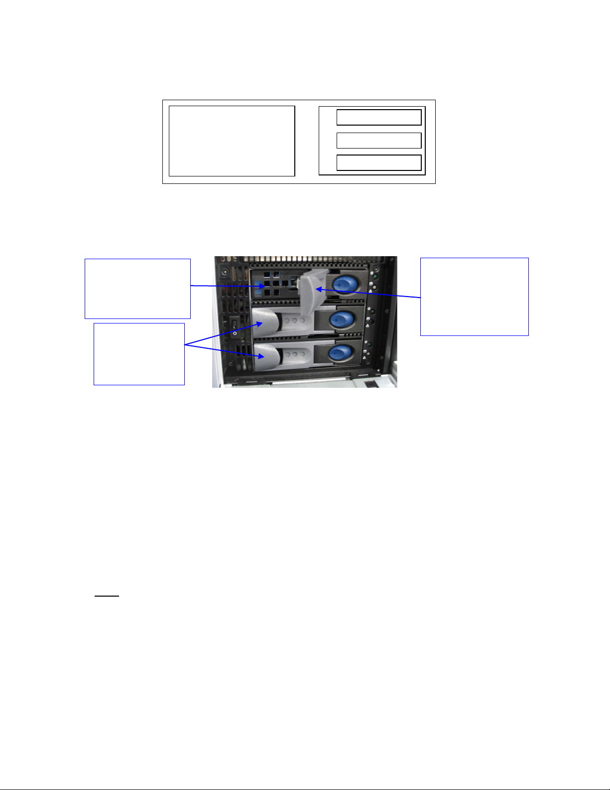
Identify the label written on each HDD. You should have one top, one center, and one
bottom (Figure 1):
HDD label location
Figure 1: HDD Label Location – Example of TOP label
For each HDD, press on the blue button located on its front side in order to release the
grey handle and open the handle all the way until it clicks (Figure 2).
Figure 2: HDD – Grey Handle Opening
Open the door covering the HDD cage, located on the right side of the front panel.
DSV.OM.000391.DRM Page 8 of 68 Version 1.3
Doremi Labs
Page 9
Insert each drive all the way, one by one, in the chassis HDD cage according to the
TOP-CENTER-BOTTOM location defined in the schema below and while making sure
that the grey handle remains open all the way to the right (Figure 3):
TOP
LCD monitor
Figure 3: DSV-J2 Front View Schema – HDDs Location
The drive shall be inserted all the way inside the HDD cage before trying to close the
grey handle. Otherwise, the drive might not be plugged in properly (Figure 4):
TOP HDD
inserted all the
way into the HDD
cage
CENTER and
BOTTOM
HDDs already
installed
Figure 4: DSV-J2 HDD Cage – HDDs Insertion
Close the grey handle by pushing it toward the HDD until it clicks. The HDD properly
installed should then look like the CENTER and BOTTOM HDDs presented in Figure 4
above.
CENTER
BOTTOM
Grey handle
opened all the
way in order to
insert the HDD
properly
Power cables can now be safely plugged into the DSV-J2.
2.2 Proper Power Off
Follow the instruction below to power off the DSV-J2 safely. Any other method might damage
the raid and result in raid failure:
Select Shut Down from the Logout menu: Menu → Logout → Shutdown
or
Press and release the Power button.
1.Note: Do not hold the Power button for more than one second. See section 3.1 for power
switch location.
To turn it back on, simply press and release the Power switch.
DSV.OM.000391.DRM Page 9 of 68 Version 1.3
Doremi Labs
Page 10
3 DSV-J2 Presentation
Thank you for choosing the Doremi DSV-J2. The DSV-J2 is a high quality JPEG-2000 server
capable of playing movie or trailer packages in MXF format at up to 250Mbits/sec.
The DSV-J2 supports playback in High Definition (1920x1080), 2K (2048x1080) and optional 4K
(4096x2160). 3D playback is supported in HD and 2K resolutions only. Super widescreen
playback (Stereoscopic) is achieved by sending a unique SDI stream to each of two projectors.
The unit features a dual-link HD-SDI output capable of 12-bit 4:4:4 2048x1080p24 or 10-bit
4:2:2 for 48fps and 3D applications. Data storage is done on an internal RAID5 disk array.
The DSV-J2 is also capable of playing MPEG2 Interop movies, pre-show, and alternative
content playback.
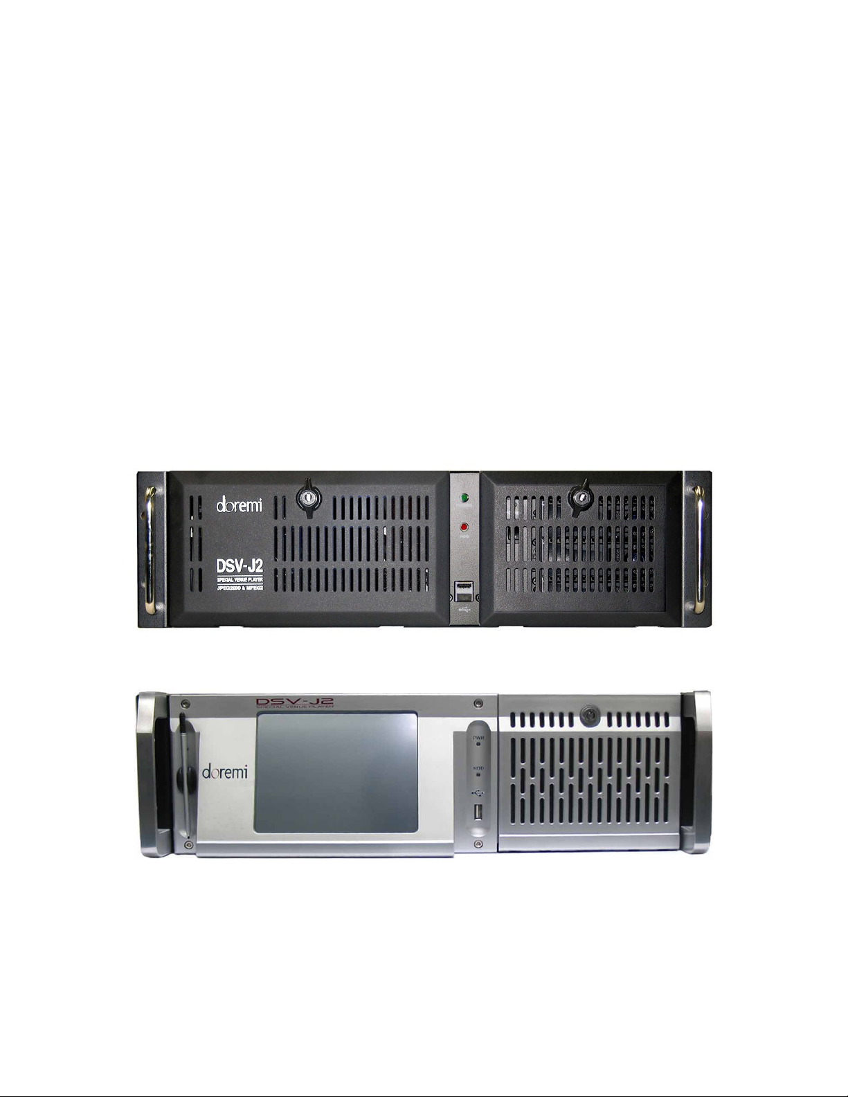
3.1 DSV-J2 Front Panel
Two different front panels are available:
A black front panel with two doors
A silver front panel without a door in front of the server LCD screen
They are presented below (Figure 5 and Figure 6):
Figure 5: DSV-J2 with Black Front Panel
Figure 6: DSV-J2 with Silver Front Panel
POWER (or PWR): Upper green LED lights when the unit is on.
HDD: Red LED indicates hard drive access.
The door on the right, for both types of front panels, covers the Power switch and the three hard
disks that make up the RAID-5 storage (Figure 7).
DSV.OM.000391.DRM Page 10 of 68 Version 1.3
Doremi Labs
Page 11
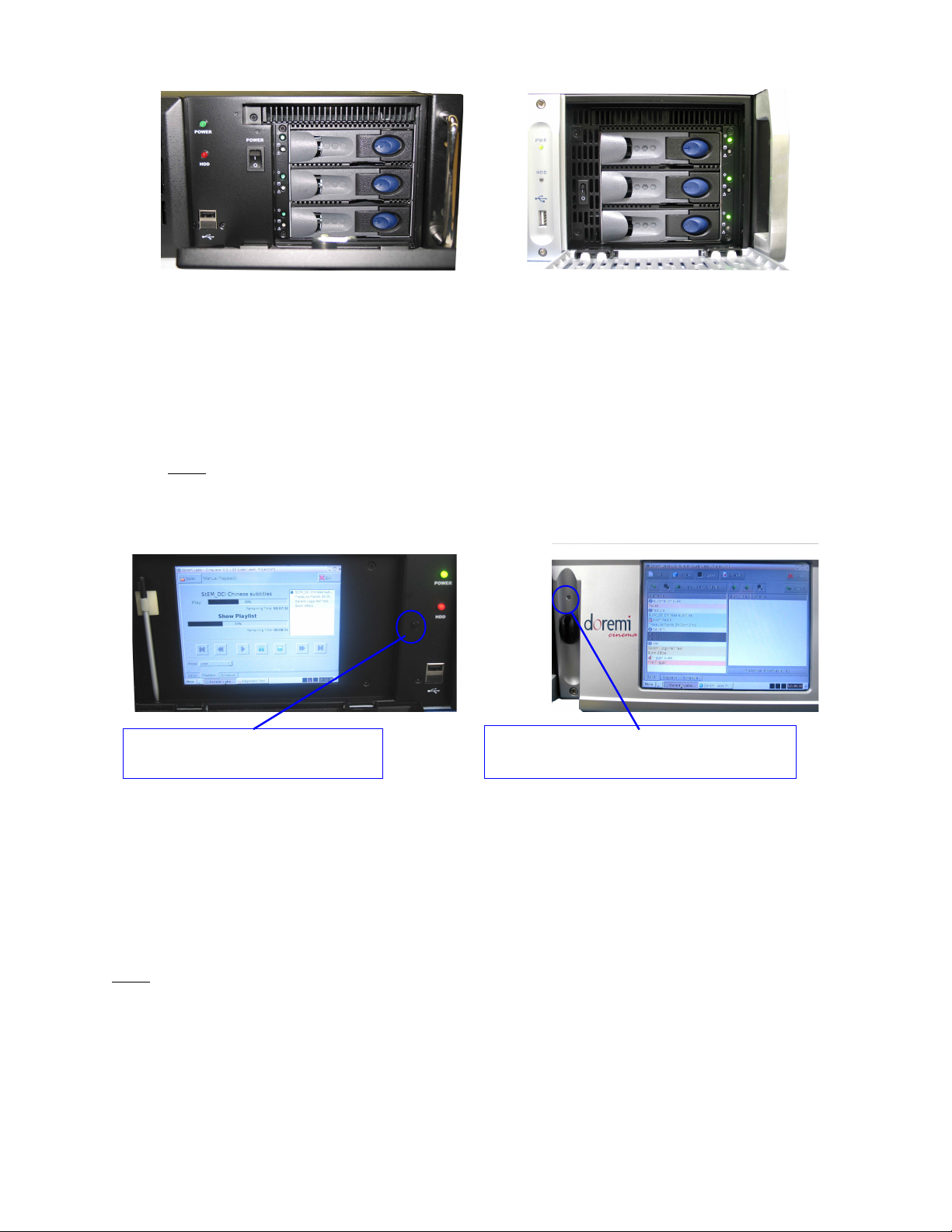
LCD power ON/OFF button –
controlled by the door
(a) (b)
Figure 7: DSV-J2 Front Panel, Right Door Opened, Three HDDs
(a) Black Front Panel, (b) Silver Front Panel
Each hard disk has a blue button that allows removal of the drive from the chassis. Be careful
not to remove the hard disk when the DSV-J2 is running.
Additionally, there is one USB 2.0 connector on the center of the front panel that can
accommodate an external hard drive as well as a mouse or keyboard.
Note: On the black front panel, two USB connectors are presents while only the upper
USB connector is active.
The left side of the front panel provides an LCD screen (covered by a door on the black chassis)
with its associated power on/off button (Figure 8):
LCD power ON/OFF button – to be
pushed with the provided stylus
(a) (b)
Figure 8: DSV-J2 Front Panel, LCD Screen
(a) Black Chassis - with left door opened, (b) Silver Chassis
On the black front panel, the LCD power on/off button is automatically controlled when opening
or closing the door that covers the LCD.
On the silver front panel, the LCD has to be turned on or off by pressing on the LCD power
button using the stylus attached to the front panel.
Note: The use of this LCD screen requires that the two rear panel VGA connectors are linked
using the VGA cable provided with the DSV-J2. See Section 4.1 for details about the VGA cable
connections.
DSV.OM.000391.DRM Page 11 of 68 Version 1.3
Doremi Labs
Page 12
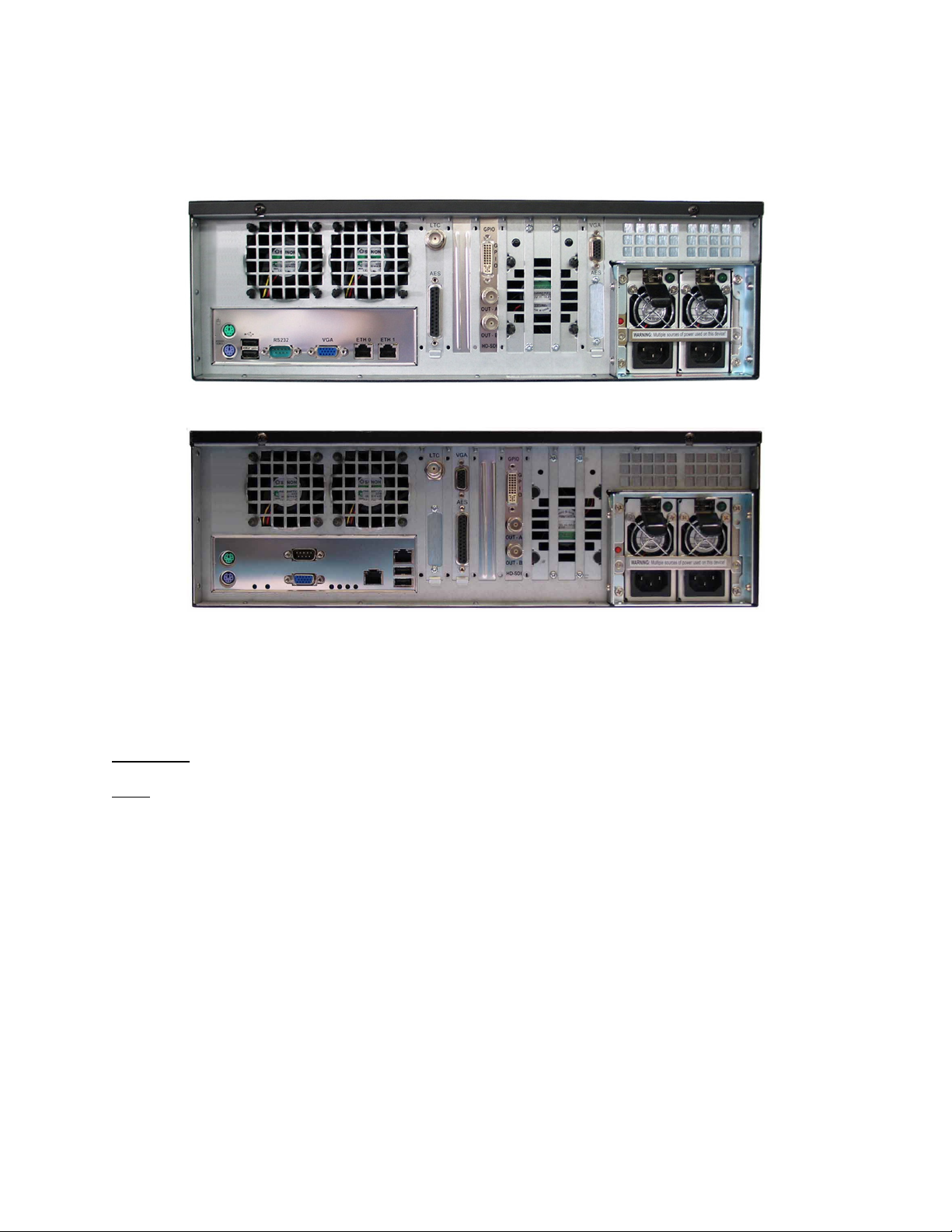
3.2 DSV-J2 Rear Panel
Two different rear panels can be found on the DSV-J2, depending on the motherboard used.
The SuperMicro motherboard is illustrated in Figure 9, while the Intel motherboard is presented
in Figure 10:
Figure 9: DSV-J2 Rear Panel – SuperMicro Motherboard
Figure 10: DSV-J2 Rear Panel – Intel Motherboard
On the right side of the rear panel is the dual-redundant power supply. Make sure that two AC
power cables are used or the unit will sound an audible alarm until both power cables are
connected. To temporarily disable the audible alarm, press the red button next to the AC power
connectors.
CAUTION: Insert drives before the power cables.
Note: Powering the DSV-J2 with only one AC cable is not recommended.
On the left side of the rear panel are the motherboard connections. These are for the keyboard,
mouse, VGA, 9-pin serial, Ethernet, and USB 2.0 connections. Please see Section 4.3 for
detailed information on motherboard connections.
DSV.OM.000391.DRM Page 12 of 68 Version 1.3
Doremi Labs
Page 13
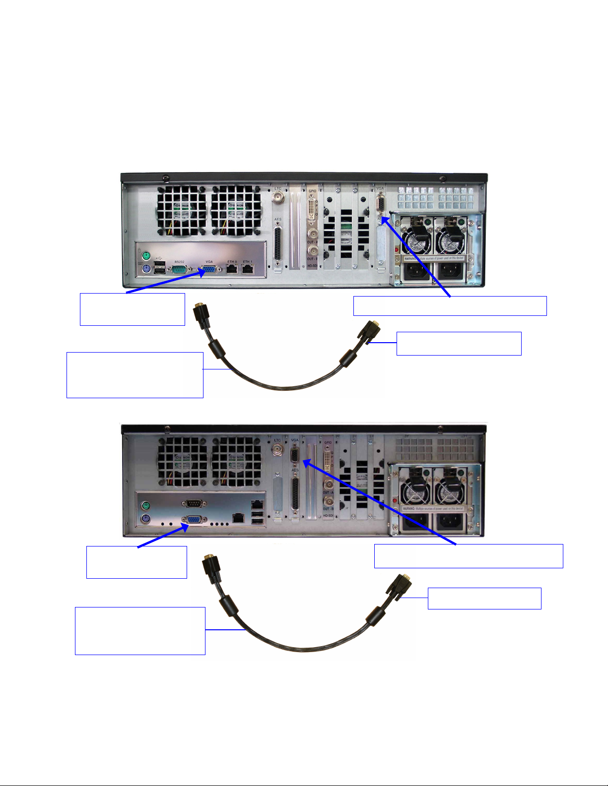
4 Rear Panel Connectors
link the two rear panel
VGA connectors
Server LCD screen VGA connector
Motherboard VGA
connector
VGA connector
4.1 VGA Cable Connection for Server LCD Screen Usage
If the front panel LCD screen needs to be used, the server LCD screen VGA connector has to
be linked to the motherboard VGA connector using the VGA cable (shown below) that is
provided with the DSV-J2. Make sure that the VGA cable is secured to the DSV-J2 VGA
connectors using the integrated screws (Figure 11 and Figure 12):
Integrated screw
VGA cable required to
Figure 11: DSV-J2 Fitted with SuperMicro Motherboard – VGA Cable Connection
Motherboard
VGA cable required to
link the two rear panel
VGA connectors
Server LCD screen VGA connector
Integrated screw
Figure 12: DSV-J2 Fitted with Intel Motherboard – VGA Cable Connection
DSV.OM.000391.DRM Page 13 of 68 Version 1.3
Doremi Labs
Page 14
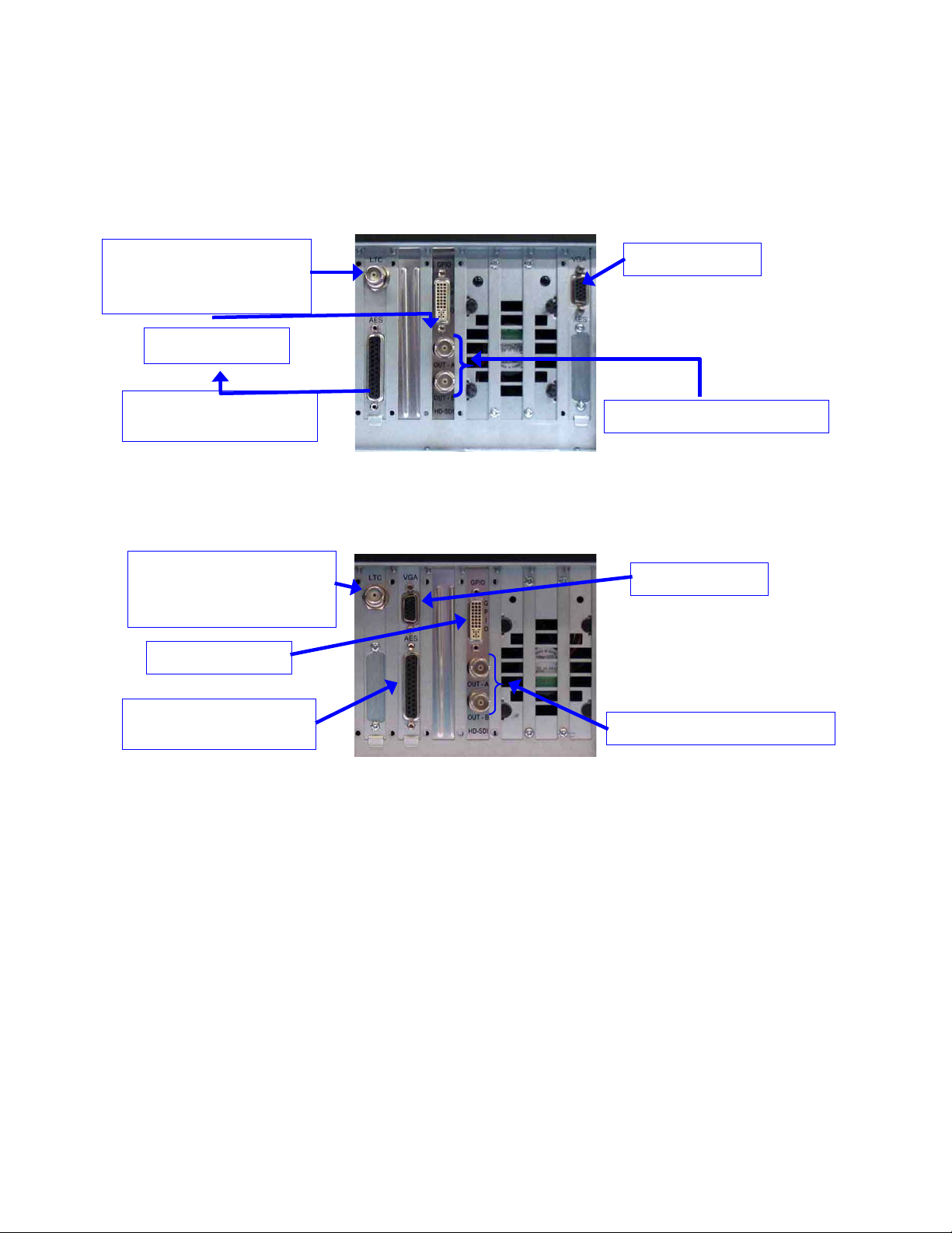
4.2 Rear Panel Card Slot Connectors
HD-SDI Output connectors
connector
VGA connector
HD-SDI Output connectors
connector
VGA connector
4.2.1 Card Slot Connectors Overview
On the center of the rear panel are the various card slot connectors. The only differences
between the two rear panel configurations presented in paragraph 3.2 is that the order of the
brackets are not the same (Figure 13 and Figure 14):
LTC output (or DolphiLock
SYNC input depending on
your options) connector
GPIO connector
AES/EBU digital audio
Figure 13: DSV-J2 Fitted with SuperMicro Motherboard - Card Slot Connectors
Use the card slot DB-25 connector for digital audio connections (4.2.3 and 4.2.4).
LTC output (or DolphiLock
SYNC input depending on
your options) connector
GPIO connector
AES/EBU digital audio
Figure 14: DSV-J2 Fitted with Intel Motherboard - Card Slot Connectors
DSV.OM.000391.DRM Page 14 of 68 Version 1.3
Doremi Labs
Page 15
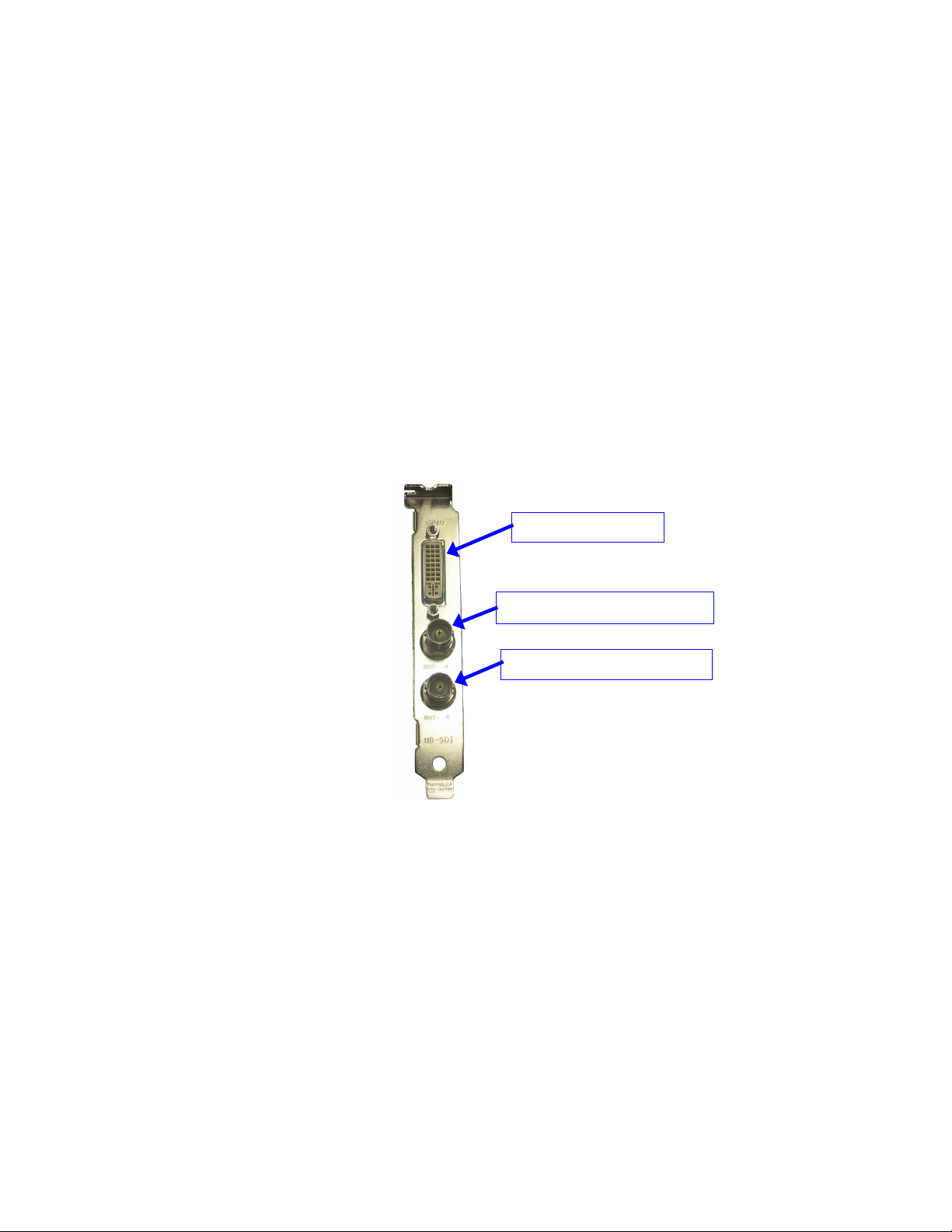
4.2.2 HD-SDI Serial Digital Interface / Dolphin DCI Decoder Card
GPIO Connector
HD-SDI Output - Link A
HD-SDI Output - Link B
Located in the rear panel card slots beside the AES/EBU audio card is the standarddefinition/high-definition serial digital interface. This is the Doremi Dolphin DCI decoder card that
contains the JPEG-2000 decoder hardware and BNC serial digital interface connectors.
The DSV-J2 utilizes a dual-link serial digital interface for output of resolutions up to
2048x1080p24 (2K-film). It can also operate single-link for lower resolution material (i.e. trailers,
advertisements, etc.).
4.2.2.1 Dolphin DCI Board Connectors
The Dolphin DCI board provides two different kinds of external connectors on the DSV-J2 rear
panel:
One GPIO (DVI-I) female connector
Two HD-SDI BNC connectors
The connectors of the Dolphin DCI board from top to bottom are: GPIO, HD-SDI OUTPUT A,
HD-SDI OUTPUT B (Figure 15):
DSV.OM.000391.DRM Page 15 of 68 Version 1.3
Figure 15: Dolphin DCI Board Bracket
Doremi Labs
Page 16
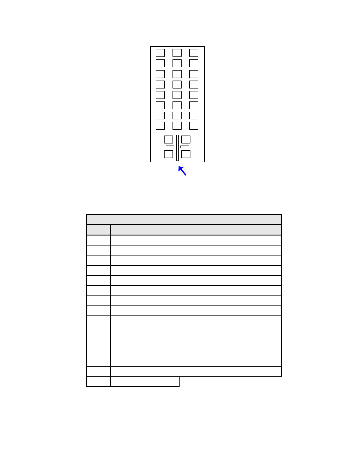
The GPIO DVI-I connector pin numbering is illustrated below (Figure 16):
17
18
19
20
21
22
23
24
9
10
11
12
13
14
15
16
C3 C1
C4 C2
C5/C6
1
2
3
4
5
6
7
8
Figure 16: Dolphin DCI GPIO (DVI-I) Female Connector
The General Purpose I/O DVI-I connector pin-out follows:
GPIO (DVI-I) Female Connector
Pin # Signal Description Pin # Signal Description
1 GPO 3 16 GPI 2-
2 GPO 2 17 GPO 7
3 GND (ground) 18 GPO 6
4 N/C 19 GND (ground)
5 N/C 20 GPO 1
6 GPI 5- 21 GPO 0
7 GPI 3- 22 GPI 5+
8 GPI 2+ 23 GPI 4+
9 GPO 5 24 GPI 3+
10 GPO 4 C1 GPI 1-
11 GND (ground) C2 GPI 0-
12 N/C C3 GPI 1+
13 N/C C4 GPI 0+
14 5V / 0.2A C5/C6 GND (ground)
15 GPI 4-
DSV.OM.000391.DRM Page 16 of 68 Version 1.3
Doremi Labs
Page 17

The GPIO cable delivered with the DSV-J2 with a Dolphin DCI installed has an exposed wire
end as shown here (Figure 17):
Connector to be
plugged into the
DSV-J2 GPIO
connector
Unwired end
Figure 17: Dolphin DCI GPIO Cable
The GPIO channels are tagged on each wire of the exposed end to facilitate GPIO channel and
signal/ground identification.
4.2.3 Digital Audio (AES/EBU)
The digital audio interface of the DSV-J2 is provided on a female DB-25 connector on the rear
panel of the unit (Figure 18). Currently, 16 channels of balanced AES/EBU digital audio are
provided. The pin-out for the digital audio connector is shown in the table that follows. The pin
numbers are defined on the front face of the female DB-25 connector (Figure 18):
Pin 25
Pin
13
Pin 2
Pin 14
Pin 1
Figure 18: Digital Audio Interface
The AES/EBU digital audio DB-25 connector pin-out follows:
DSV.OM.000391.DRM Page 17 of 68 Version 1.3
Doremi Labs
Page 18
Pin
#
1 Ch 15 & 16 plus 14 Ch 15 & 16 minus
2
3 Ch 13 & 14 minus 16 Ch 13 & 14 ground
4 Ch 11 & 12 plus 17 Ch 11 & 12 minus
5
6 Ch 9 & 10 minus 19 Ch 9 & 10 ground
7 Ch 7 & 8 plus 20 Ch 7 & 8 minus
8 Ch 7 & 8 ground 21 Ch 5 & 6 plus
9 Ch 5 & 6 minus 22 Ch 5 & 6 ground
10 Ch 3 & 4 plus 23 Ch 3 & 4 minus
11 Ch 3 & 4 ground 24 Ch 1 & 2 plus
12 Ch 1 & 2 minus 25 Ch 1 & 2 ground
13 no connection
Signal
Description
Ch 15 & 16
ground
Ch 11 & 12
ground
Pin
Signal Description
#
15 Ch 13 & 14 plus
18 Ch 9 & 10 plus
4.2.4 Analog Audio
DCI Channel Map:
Channel 1: L (screen – left)
Channel 2: R (screen – right)
Channel 3: C (screen – center)
Channel 4: LFE (screen – low
frequency effects
subwoofer)
Channel 5: Ls (surround – left wall)
Channel 6: Rs (surround –
right
wall)
Channel 7: Lc (screen – mid left
to center)
Channel 8: Rc (screen – mid right
to center)
Analog audio interface can be available by purchasing a Doremi AUD-D2A external digital to
analog audio converter.
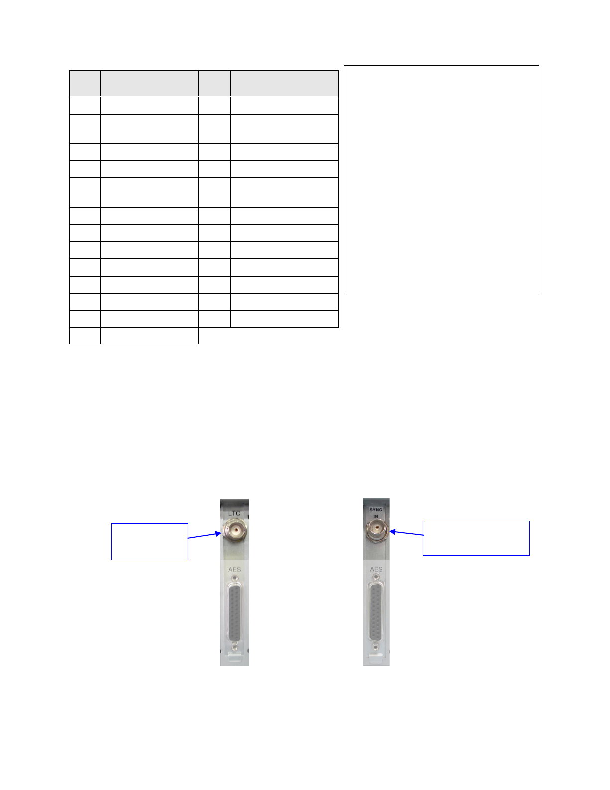
4.2.5 LTC or DolphiLock Connector
For the BNC connector located above the AES connector, two options are available:
a LTC output (Figure 19) or
a DolphiLock input (SYNC Input, Figure 19).
LTC output
connector
OR
DolphiLock - SYNC
input - connector
(a) (b)
Figure 19: (a) LTC Output Connector – (b) DolphiLock (SYNC Input) Connector
DSV.OM.000391.DRM Page 18 of 68 Version 1.3
Doremi Labs
Page 19
With the LTC Output option (flagged with “LTC” mark above the BNC connector), the
Mouse
VGA
(Eth0)
Mouse
(Eth0)
Keyboard
connector outputs the linear time-code (LTC) compliant with SMPTE 12M.
With the DolphiLock option (flagged with “SYNC IN” mark above the BNC connector), the
connector is a SYNC input. It can be used to synchronize the Dolphin DCI board, thus the
playback, with an external device.
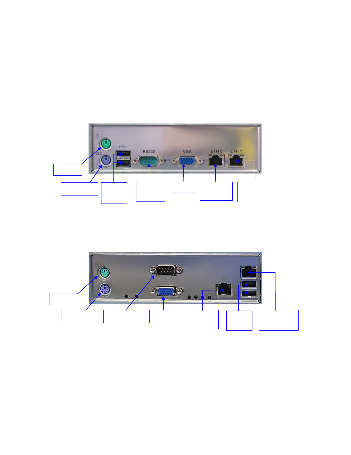
4.3 DSV-J2 Motherboard Connections
4.3.1 Motherboard Connectors
4.3.1.1 SuperMicro Motherboard Connectors
USB
Ports
Ethernet
(Eth1)
Ethernet
(Eth1)
Keyboard
Figure 20: Rear Panel – SuperMicro Motherboard Connectors
On the rear panel of the unit are the connections to the motherboard (Figure 20). These
connectors are described in Sections 4.3.2 to 4.3.6.
4.3.1.2 Intel Motherboard Connectors
On the rear panel of the unit are the connections to the motherboard (Figure 21). These
connectors are described in Sections 4.3.2 to 4.3.6.
USB
Ports
Serial Port VGA Ethernet
Figure 21: Rear Panel – Intel Motherboard Connectors
Serial
Port
Ethernet
DSV.OM.000391.DRM Page 19 of 68 Version 1.3
Doremi Labs
Page 20

4.3.2 Keyboard & Mouse PS-2 Connectors
On the left side of the connector panel are the PS-2 connectors for the PC keyboard and
mouse. These jacks can be used interchangeably, but traditionally the purple jack is for a PC
keyboard and the green jack is for a PS-2 mouse. If you have a USB keyboard or mouse, then
use the USB ports on the right side of the motherboard connector panel. You may also use the
upper USB port on the front panel of the unit for connecting the keyboard and mouse.
4.3.3 Serial Port
This is a standard 9-pin male DB-9 serial COM port on the motherboard.
4.3.4 VGA
Connect a standard VGA monitor here for display of the DSV-J2 software interface.
This connector can also be linked to the center rear panel VGA connector to facilitate use of the
front panel LCD screen. The VGA cable provided with the DSV-J2 (Section 4.1) is then required.
4.3.5 USB Ports
Connect standard USB 2.0 peripherals here such as a PC USB keyboard, mouse, hard drive,
etc.
4.3.6 Ethernet
The Motherboard has two built-in Gigabit Ethernet connectors. The left one is identified as Eth0
and the right one is identified as Eth1.
DSV.OM.000391.DRM Page 20 of 68 Version 1.3
Doremi Labs
Page 21
5 DSV-J2 IP Address
All DSV-J2 servers are shipped with a default IP address of 192.168.100.50 on the Ethernet
port (Eth1) and a DHCP assigned dynamic IP address on the Ethernet port (Eth0). See section
4.3 to locate each Ethernet connector.
To change the IP address of the DSV-J2 server, go to Menu → System → Networking Setup
and follow the steps below:
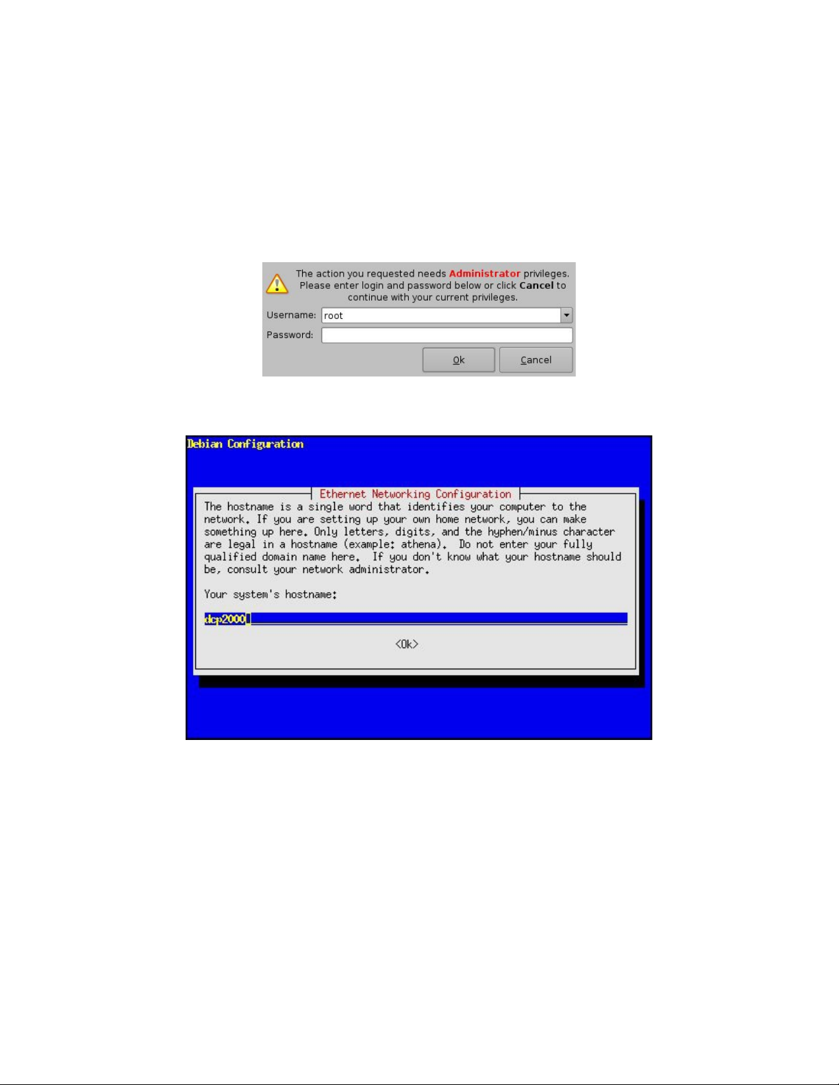
From the DSV-J2 menu, select Menu → System → Networking Configuration and
you should be asked for a password (Figure 22):
Figure 22: Authentication Windows
Then follow the steps starting with the following windows (Figure 23):
Figure 23: DSV-J2 Network Configuration
In the steps that follow, use the arrow down or the Tab key to select OK then hit <enter>:
1.) Enter the desired system’s hostname and select OK.
2.) Select OK for your system's domain name.
3.) Select Yes for eth0.
4.) Select No for Removable Device.
5.) Select No for automatically configure device with DHCP.
6.) Enter the desired IP address for eth0 and select OK.
7.) Enter the desired default gateway or leave empty and select OK.
8.) Enter the desired subnet mask and select OK.
DSV.OM.000391.DRM Page 21 of 68 Version 1.3
Doremi Labs
Page 22

9.) Enter the desired device broadcast address then select OK.
10.) Select Yes for eth1.
11.) Select No for Removable device.
12.) Select No for automatically configure device with DHCP.
13.) Enter the IP address of eth1 and select OK. In our example, enter 192.168.10.12.
14.) Enter the desired default gateway or leave empty and select OK.
15.) Enter the desired subnet mask and select OK. In our example, enter the same subnet
mask as the projector: 255.255.255.0.
16.) Enter the desired device broadcast address then select OK. In our example, enter
192.168.10.255.
17.) Leave empty the system’s domain name servers and select OK.
You will now exit the setup utility.
To verify your setup, go to Menu → Doremi Apps. → Diagnostic Tool and verify the IP
Address under the Diagnostic Tool System Tab.
DSV.OM.000391.DRM Page 22 of 68 Version 1.3
Doremi Labs
Page 23

6 Device Manager Configuration
The Device Manager is a graphical user interface used to setup the connection between a DSVJ2 and cinema projector(s). It also provides for the use of Ethernet commands for the control of
theater automation devices.
To run the Device Manager, go to Menu → Doremi Apps. → Device Manager.
The following window should appear on the screen (Figure 24):
Add
button
Figure 24: Device Manager Graphical User Interface (GUI)
6.1 Projector(s) Management
The DSV-J2 to projector setups does not have Cinelink encryption and therefore the projector
should not be setup in the Device Manager.
6.2 Automation Libraries Management
Support for theater automation control through Ethernet is also provided. The list of currently
supported devices is the following:
eCNA
JNior
A pre-built library of supported automation commands is available for each of these two devices.
These automation commands can then be added to Macro Cues as presented in section 7.2.
6.2.1 eCNA Device
6.2.1.1 eCNA Device Addition
To use the eCNA device, click the Add button and select eCNA.
Then enter the eCNA device IP address in the appropriate field as presented below (Figure 25):
DSV.OM.000391.DRM Page 23 of 68 Version 1.3
Doremi Labs
Page 24

Add
Enabled
checked
button
Delete
button
eCNA IP
address
field
Figure 25: Device Manager GUI – eCNA Device Setup
Make sure the Enabled field is checked in the top-right corner of the GUI.
Click the Save button in order to record your settings. You should be asked for a password.
6.2.1.2 eCNA Device Removal
To remove the eCNA device, select it in the left pane of the Device Manager and click the
Delete button (Figure 25).
DSV.OM.000391.DRM Page 24 of 68 Version 1.3
Doremi Labs
Page 25
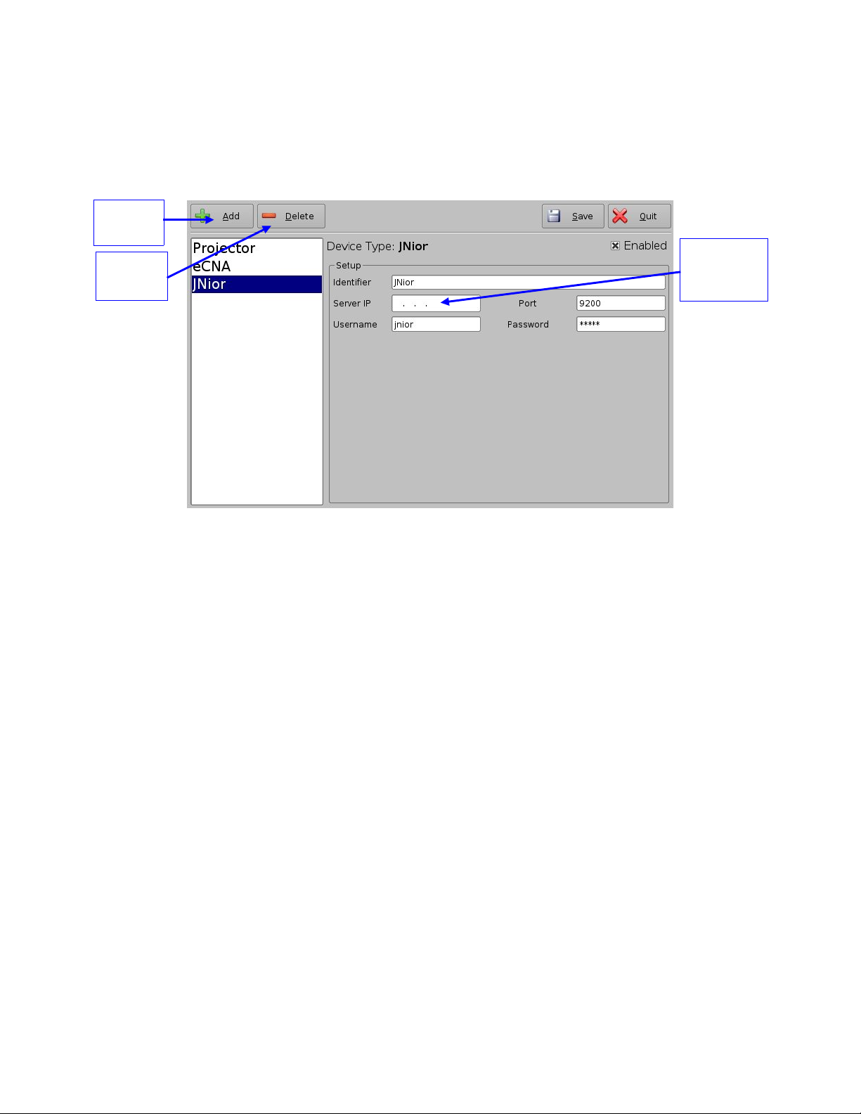
6.2.2 JNior Device
JNior IP
address
field
button
6.2.2.1 JNior Device Addition
To use the JNior device, click the Add button and select JNior. The JNior device setting window
should be displayed within the Device Manager (Figure 26):
Add
Delete
button
Figure 26: Device Manager GUI – JNior Device Setup
Enter the IP address of the JNior device in the Server IP field – the port number field should
already contain the appropriate value (factory default value).
The JNior device documentation should provide you the correct Username and Password
values (the factory default values).
Click the Save button to record the settings. You should be asked for a password.
6.2.2.2 JNior Device Removal
To remove the eCNA device, click on its name on the left part of the Device Manager GUI and
click the Delete button (Figure 26).
DSV.OM.000391.DRM Page 25 of 68 Version 1.3
Doremi Labs
Page 26

6.3 Raw Device
button
6.3.1 Raw Device Addition
A Raw device allows for communication with an external device across an Ethernet connection
using Raw data formatted as text or binary strings.
To use a Raw device, click the Add button and select Raw. The Raw device setting window
should be displayed within the Device Manager (Figure 27):
Add
Device IP
Delete
button
address
field
Port number
field
Protocol
selection
Figure 27: Device Manager GUI – Raw Device Setup
Enter the IP address of the Raw device in the Device IP field.
Chose the protocol to be used (TCP or UDP) and the proper Port number.
Click on Save to record the settings. You should be asked for a password.
6.3.2 Raw Device Removal
To remove the Raw device, click on its name on the left part of the Device Manager GUI and
click the Delete button (Figure 27).
6.4 3D Setup
6.4.1 Projector Configuration for 3D or 48fps
In 3D or 48fps mode, the DSV-J2 video output is in the YCxCz color space. The projector itself
needs to be properly configured to the YCxCz color space in 3D or 48fps mode for proper
display. Contact your projector vendor to find out how to configure the projector properly.
6.4.2 Dolby 3D Support
To enable the Dolby 3D support, please contact Doremi to get the appropriate license.
DSV.OM.000391.DRM Page 26 of 68 Version 1.3
Doremi Labs
Page 27

7 Automation Set Up: Macro Editor Usage
Automation events can be created using the Macro Editor for use within the CineLister interface.
The paragraphs below detail how to generate and manage automation events as part of Macro
Automation Cues and/or Trigger Cues.
7.1 Macro Editor Interface Overview
In order to run the Macro Editor, go to the Start menu of the server, then to Doremi Apps. and
choose the item Macro Editor.
The graphical user interface (GUI) should appear on the screen (Figure 28):
Quit button
Add
button
Trigger
Cue tab
Automation
Cue tab
Figure 28: Macro Editor Graphical User Interface (GUI)
The GUI presented above is composed of two different tabs:
Automation Cue Tab – used for the creation and editing of Macro Automation Cues.
Trigger Cue Tab – used for the creation and editing of Trigger Cues linked to dedicated
Macro events (e.g. on GPI line #1 ON, execute Macro xxMACRO NAMExx).
The Quit button is used to close the Macro Editor user interface.
DSV.OM.000391.DRM Page 27 of 68 Version 1.3
Doremi Labs
Page 28

7.2 Automation Cue Tab
7.2.1 Macro Creation
Click the Add button to start the creation of a new Macro Automation Cue (Figure 28). The
following window should be displayed (Figure 29):
Macro Automation
Cue name
Figure 29: Macro Automation Cue Name Assignment
Enter a Macro Automation Cue name in the appropriate field. It will be the name used by the
CineLister application in order to include this Macro Automation Cue within a Show Playlist.
Click the Ok button when you are done. You should be back to the general Macro Editor GUI
displaying the Macro Automation Cue name in the Macro Window (Figure 30):
Edit button
Remove
button
Macro
window
Figure 30: Macro Window Updated
To remove a Macro Automation Cue, select it in the Macro window and click the Remove button
(Figure 30).
To edit the name of an existing Macro Automation Cue, click the Edit button and do the change
(Figure 30).
Macro Automation
Cue name
displayed
Insert a New
Action button
DSV.OM.000391.DRM Page 28 of 68 Version 1.3
Doremi Labs
Page 29

7.2.2 Action Insertion
To insert a new action in a Macro Automation Cue, select its Macro name in the Macro Window
and click the Insert a New Action button.
The following window should be displayed (Figure 31):
Figure 31: Action Window
The Action Window provides a list of available actions to be used within a Macro Automation
Cue.
The actions available are the following:
Delay: delay the macro execution for a specific duration
General Purpose Output: change the position of a GPO line
Projector Dowser: open or close the projector dowser
Projector Lamp: turn the projector lamp on or off
Projector Channel Switch: switch to a projector channel number from 1 to 16
Projector Macro: used to recall preset DLP projector macros by name (e.g. for Barco)
Playback Actions: select an action between Play, Pause or Toggle Play/Pause
Video Output Action: choose between Default Video Output and Play all clips at 48fps
Send Message: used for sending a text or a binary message to a device
Library: used for sending a pre-defined message to a specific device (e.g. eCNA, JNior)
Purge Pending Macro: used to purge pending macros
Click the Cancel button to cancel the action insertion.
To add an action to the Macro Automation Cue, click on its corresponding Action button in the
Action window.
DSV.OM.000391.DRM Page 29 of 68 Version 1.3
Doremi Labs
Page 30

Example of Delay Action Insertion
To add a delay action to the selected Macro Automation Cue, click the Delay button in
the Action window and define the delay parameter using the following window (Figure
32):
Button used to
increase or
decrease the
amount of minutes
Button used to
increase or
decrease the
amount of seconds
Figure 32: Delay Setup Window
Click on the Ok button when the setting is done.
Example of GPO Action insertion
To add a GPO action, click the General Purpose Output button in the Action window
(Figure 31). The following window will appear (Figure 33):
Buttons used to
GPO state button
choose the GPO line
number
Figure 33: GPO Setup Window
Set the line number and value according to the usage you plan for this action and
click the Ok button.
Example of Playback Action Insertion
To add a Playback Action, click the Playback Actions button in the Action window
(Figure 31). The following window should appear (Figure 34):
Playback Action
Play button
Figure 34: Playback Actions Setup Window
Select the proper playback action between Play, Pause, or Toggle Play/Pause and click
the Ok button.
DSV.OM.000391.DRM Page 30 of 68 Version 1.3
Doremi Labs
Page 31

Example of Automation Library Usage
Edit Action
button
Remove
button
When one of the supported devices (e.g. eCNA and JNior) is added according to Section
6.2, the Macro Editor should allow you to use the corresponding commands for each device.
In order to do this, follow the procedure below:
1. To use a library command, click on Library in the Action window (Figure 31).
2. Select one of the available devices in the left part of the following window and choose
the appropriate command (belonging to the selected device) in its right part (Figure 35):
Selected
device
Chosen command
Figure 35: Macro Editor GUI – eCNA Automation Setup Example
3. Click the Ok button to validate, or Cancel to cancel this command addition.
Example of Resulting Macro Setting
After having inserted the three actions “Delay 1s,” “GPO line #3 ON,” and “Playback: Play”
in the Macro “Test_Macro” as called in this example, the right part of the Automation Cue
tab should display the added actions (Figure 36):
Save
button
Arrow
buttons
Selected Macro
automation
List of actions
inserted into the
“Test_Macro“
element
Figure 36: Example of Macro Actions Window Updated
Click the Save button to save the “Test_Macro” settings. A password will be needed.
DSV.OM.000391.DRM Page 31 of 68 Version 1.3
Doremi Labs
Page 32

7.2.3 Action List Management
Action Reordering
Two arrows allow the user to change the order of the actions in the Macro Automation Cue
(Figure 36). Using those arrows, each action can be moved to the top or to the bottom of the
Macro Actions window:
In order to move an action to the top, select it and click on the arrow pointing to the top.
If an action needs to be moved to the bottom of the Macro Actions window, select it and
click on the arrow pointing to the bottom.
Repeat these operations until the required actions order is obtained.
Action Edition
You can edit an action of a given Macro Automation Cue by selecting it in the right part of
the interface and by clicking the Edit Action button (Figure 36).
You will be able to edit the properties you were asked to set when the action was added to
the Macro Automation Cue.
Action Removal
To remove an action from the list of actions associated to a Macro Automation Cue, select
the action in the Macro Actions window and click the Remove button (Figure 36).
7.2.4 Macro Saving
Repeat the Macro creation operations for all the Macro Automation Cues you need to create
and click the Save button. You will be asked for a password to be able to perform this operation
(Figure 37):
Figure 37: Authentication Window
Enter the appropriate password and click the Ok button. These Macro Automation Cues will be
available in CineLister in order to create a Show Playlist.
Note that this saving operation will not only save the Macro Automation Cues, but also the
Trigger Cues that were created according to the procedure described in the following section.
DSV.OM.000391.DRM Page 32 of 68 Version 1.3
Doremi Labs
Page 33

7.3 Trigger Cue Tab
7.3.1 Trigger Cue Tab Overview
The Trigger Cue Tab is shown below (Figure 38):
Add button to
be used to
add a new
Trigger Cue
Trigger
window
Figure 38: Trigger Cue Tab
7.3.2 Trigger Cue Creation
To create a new Trigger Cue, click the Add button presented in the previous figure. The same
type of window as for the Automation Cue tab that allows you to enter the Trigger Cue name will
appear (Figure 39):
Figure 39: Trigger Cue Setting Window
Enter the appropriate name. It will be the name used by the CineLister application to insert this
Trigger Cue in a Show Playlist.
DSV.OM.000391.DRM Page 33 of 68 Version 1.3
Doremi Labs
Page 34

The newly created Trigger Cue will appear in the Trigger window, ready to be connected to a
Connect to an
Event button
Edit Trigger
button
Delete
button
GPI event (Figure 40):
New Trigger
Cue created
Figure 40: Trigger Cue Defined
To edit an existing Trigger Cue, select it in the Trigger window and click on the Edit Trigger
button shown in the figure above. You will be able to edit the name of the Trigger Cue using the
same kind of window as presented in Figure 39.
To remove a Trigger Cue, select it in the Trigger window and click the Delete button (Figure 40).
7.3.3 Connection to an Event
To connect a Trigger Cue to an event, select it in the Trigger window and click the
Connect to an Event button (Figure 40). The following window should appear (Figure
41):
Figure 41: Choose the Event to Add Window
To connect the selected Trigger Cue to a GPI event, click the General Purpose Input
button of the Choose the Event to Add window (Figure 41). The following windows
should appear (Figure 42):
DSV.OM.000391.DRM Page 34 of 68 Version 1.3
Doremi Labs
Page 35

Figure 42: Connection to a GPI Event
Define the GPI line number and value you want to connect to the Trigger Cue and click
the Ok button when you are done. The connected GPI event will then appear in the right
part of the GUI.
To connect the selected Trigger Cue to another signal, click the Signal button of the
Choose to an Event to Add window (Figure 41). The following window should appear
(Figure 43):
Figure 43: Signal Name Window
Click the Ok button when the appropriate signal name is defined.
7.3.4 Trigger Cue Saving
Repeat the Trigger Cue creation operations for all the Trigger Cues you need to create and click
the Save button. You will be asked for a password to be able to perform this operation (Figure
44):
Figure 44: Authentication Window
Enter the appropriate password and click the Ok button. These Trigger Cues will then be
available within CineLister in order to create a Show Playlist.
Note that this saving operation will not only save the Trigger Cues, but also the Macro
Automation Cues that were created according to the procedure described in Section 7.2.
DSV.OM.000391.DRM Page 35 of 68 Version 1.3
Doremi Labs
Page 36

7.4 Pre-defined Macro Usage
If you have a pre-defined macros.xml file containing automation and trigger cue definitions, just
copy it into the /doremi/etc/ folder and the corresponding macros will be visible in the Macro
Editor GUI. You should then be able to update these cues if needed from the Macro Editor GUI
as presented in the previous paragraphs.
7.5 Default Cues
The default_cues.xml file can be used to load automation and trigger cues playlists prior to any
playback (e.g., to avoid having to add a Fire Alarm trigger cue to each show). If you are
provided a default_cues.xml file, just copy it into the /doremi/etc/ folder.
DSV.OM.000391.DRM Page 36 of 68 Version 1.3
Doremi Labs
Page 37

8 Time Zone Set Up
DSV-J2 units may or may not be localized with your time zone. This section provides you
information on how to check and/or change the time zone.
8.1 Checking the Time Zone
To confirm that the time zone of your DSV-J2 is set correctly, open a terminal window by going
to the Menu → System → Terminal menu of the DSV-J2. Then do the following:
type: date <enter>
The current time and time zone will be displayed
8.2 Changing the Time Zone
To change the time zone, follow the steps below:
type: su <enter>
Then type the root password in order to login as root - consult your system administrator
to know your root password or Doremi to know the default root password.
type: /sbin/rwdo tzsetup <enter>
Then follow the graphical wizard
type: reboot <enter>
After this point in the manual, the installation should be completed and you should be able to
use the DSV-J2 within your system. The information provided in the following sections is
provided for reference.
DSV.OM.000391.DRM Page 37 of 68 Version 1.3
Doremi Labs
Page 38

9 Vendor Specific Projector Set Up Instructions
Add button
Delete
button
Vendor IP field
9.1 Adding a Christie Projector
To add a Christie CP2000 projector, run the Device Manager as presented in section 6 by going
to the Menu → Doremi Apps. → Device Manager menu of the DSV-J2.
The GUI illustrated in Figure 24 should appear on the screen. Click the Add button. The window
presented below, allowing you to add a projector, should be displayed (Figure 45).
Projector item
selected
Figure 45: Device Selection Windows – Projector Item Selected
Select Projector and click the Add button (Figure 45). You will return to the main GUI window to
enter the projector parameters (Figure 46):
Projector Identifier
Projector model set to
Christie
DLP Head IP field
Figure 46: Device Manager GUI – Christie Projector Setup Fields
DSV.OM.000391.DRM Page 38 of 68 Version 1.3
Doremi Labs
Page 39

To perform the projector setup, follow the steps below:
1. Specify a projector identifier in the first field – especially if you setup several projectors.
2. Choose the correct projector model (Christie).
3. Enter the DLP Head IP address, then click on the test button located at the right, that should
have been activated. This is an IP 'ping' test to the DLP head to verify ethernet connectivity.
4. Enter the Vendor IP value in the corresponding field. It should be set to the TPC address.
5. Enable or disable subtitles if needed using the corresponding radio buttons on the bottom of
this GUI.
6. Specify if this is the primary projector or not using the corresponding radio button. This is
useful mainly when there are several projectors configured.
Note: The DLP Username and Password are used for specific projectors only and cannot be
changed.
7. Make sure that the Enabled check box is selected at the top right corner of the GUI.
8. Click on Save to record these settings. You should be asked for a password.
9.2 Adding a NEC Projector
To add a NEC projector, perform the same procedure as in the previous paragraph using NEC
for the Projector Model field and choose the appropriate NEC projector model (Figure 47):
Delete
button
Figure 47: Device Manager GUI – NEC Projector Setup Fields
Click the Save button to record these settings. You should be asked for a password.
Projector Identifier
Projector model set
to NEC and NEC
model number
DLP Head IP field
Vendor IP field
DSV.OM.000391.DRM Page 39 of 68 Version 1.3
Doremi Labs
Page 40

9.3 Adding a Barco Projector
To add a Barco projector, perform the same procedure as in paragraph 9.1 using Barco for the
Projector model field (Figure 48). No Vendor IP is needed.
Delete
button
Figure 48: Device Manager GUI – Barco Projector Setup Fields
Click the Save button to record these settings. You should be asked for a password.
Projector Identifier
Projector model
set to Barco
DLP Head IP field
DSV.OM.000391.DRM Page 40 of 68 Version 1.3
Doremi Labs
Page 41
10 DSV-J2 Software/Firmware USB Upgrade
firmware version
Instructions
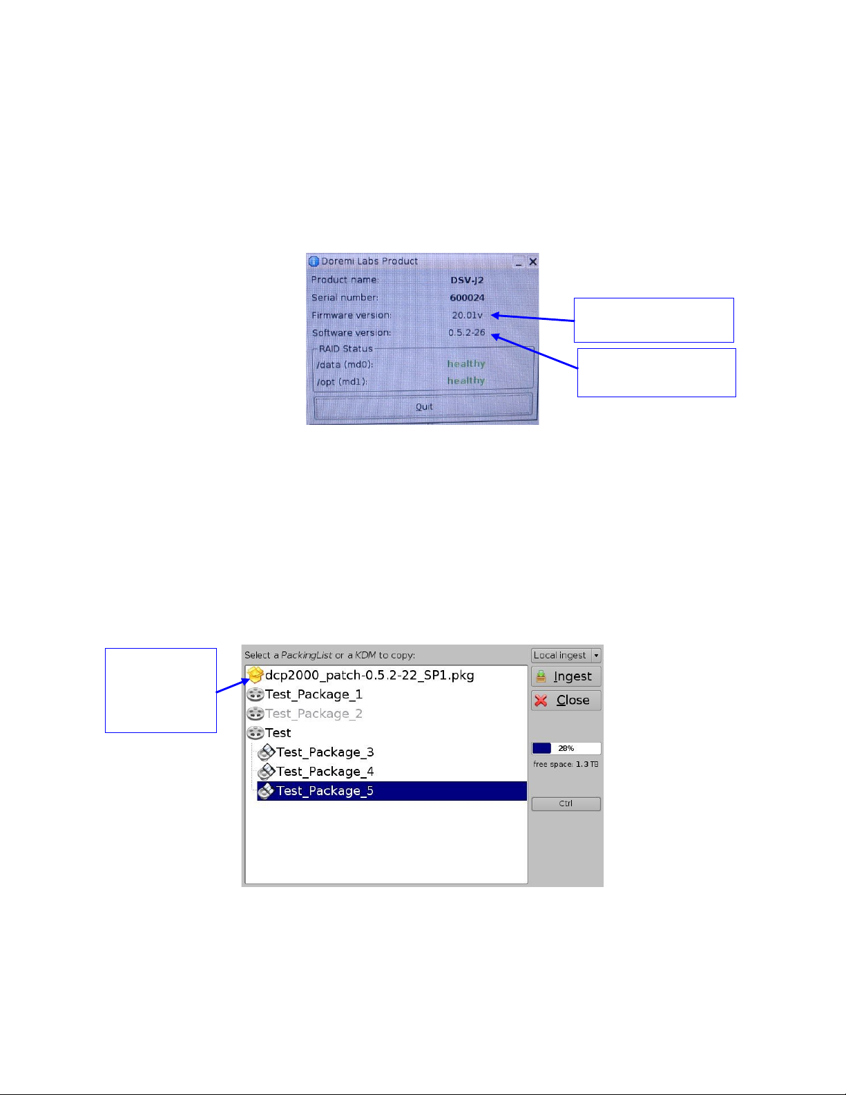
10.1 Displaying the DSV-J2 Software/Firmware Versions
To display the software version of the DSV-J2, go to the Menu → Doremi Apps. → About
menu of the DSV-J2.
The following window will appear on the screen (Figure 49):
Dolphin Board
DSV-J2 software
version
Figure 49: About Window – Software/Firmware Versions
10.2Updating Firmware/Software via USB
If you are unsure about the current software/firmware revisions, contact Doremi Technical
Support for information and downloading instructions. Once you have downloaded the update, it
can be ingested through the Ingest GUI from a USB drive:
Transfer the update file to a USB drive.
Plug the drive into the DSV-J2.
Then wait for the graphical user interface to appear on the screen (Figure 50):
Example of
software
package for
update
Figure 50: Graphical User Interface
DSV.OM.000391.DRM Page 41 of 68 Version 1.3
Choose the update from the list of files displayed in the above GUI.
Doremi Labs
Page 42

Click on Ingest. You will be asked for a password to be able to perform this operation
(Figure 51):
Figure 51: Authentication Window
Enter the appropriate password and select Ok.
When the ingest is complete, reboot the DSV-J2 by going to Menu → Logout, then click
the Reboot button. The update will not be applied without rebooting the unit.
DSV.OM.000391.DRM Page 42 of 68 Version 1.3
Doremi Labs
Page 43

11 DSV-J2 Linux Terminal Commands
The DSV-J2 uses the Linux operating system. Here are some basic instructions on how to
navigate the Linux interface and access setup options to configure your system.
11.1 Linux Login & Terminal Window (Local Connection)
Connect a standard VGA monitor, keyboard, and mouse to the DSV-J2 and power up the unit.
Note: For more information on how to connect peripheral hardware, please see sections 3 and
4.
After the DSV-J2 boots up at power on, a login window comes up within the Linux GUI. To login,
type the following:
login: root <enter>
password: xxxxx <enter> // consult your system administrator for the root password or
Doremi to know the default root password.
This is the default login name and password for the DSV-J2. Use this login for basic setup
and configuration of the DSV-J2. To change the login password, see section 11.9. If the
password has already been changed, contact your system administrator for the new password.
Once you have logged in, you will see the Linux desktop. Next, open a terminal window. To do
this, click the terminal icon on the taskbar or select Menu → System → Terminal from the
Linux programs menu in the lower left corner of the GUI.
11.2 Linux Login & Terminal Window (Remote Connection)
To login to the DSV-J2 from a remote computer, you need to use a “ssh” – a secured shell
terminal.
11.2.1 Remote Login From a Linux PC
To login to the DSV-J2 remotely, you need to know the IP address of the DSV-J2 that you want
to connect to.
From a Linux PC terminal command line,
type: ssh <DSV-J2 IP address> <enter>
An example would be:
type: ssh 192.168.100.50 <enter>
This will bring up the login window on the remote DSV-J2. Login as follows:
login name: root <enter>
password: xxxxx <enter> // consult your system administrator to know the root
password or Doremi to know the default root password
You should now be connected to the selected DSV-J2 remotely.
DSV.OM.000391.DRM Page 43 of 68 Version 1.3
Doremi Labs
Page 44

11.2.2 Remote Login From a Windows PC
From a Windows PC, you need to install a ssh client in order to login remotely. An example ssh
client is “PuTTY,” a free ssh client that can be found on the internet. The connection and login
process is similar to that described in section 11.2.1 for a Linux PC.
11.3 Displaying the Dolphin Firmware/Software Version
To display the DSV-J2 software and the Dolphin board firmware version of the DSV-J2, type the
following command from a terminal command prompt:
type: /doremi/bin/drminfo.out <enter>
This command will print out the following info (specific to your machine):
+ – – – – – – – – – – – – – – +
| Doremi Labs, Inc. |
+ – – – – – – – – – – – – – – +
Product name : DSV-J2
Serial number : 600024
Firmware version : 20.1v
Software version : 0.5.2-26
11.4 Generating Status Reports
When a problem appears on the DSV-J2 (i.e. freezes, loses video, or audio output, etc.), a
report can be generated that gives detailed technical information on the nature of the problem.
This file can be sent via email (or FTP) to the engineers at Doremi Labs to determine the reason
for the problem and to address any fixes/updates that may be needed to resolve the issue.
To generate a status report, execute the following command from the terminal prompt after the
problem occurs and before rebooting the server:
type: sh /doremi/sbin/report.sh <enter>
This command will generate a report file in the /doremi/tmp folder. You can then connect via
FTP and bring this file in to send it (via email or FTP) to Doremi engineering for analysis.
To write the report file to a USB drive, do the following:
1) Plug in the USB drive, it will be automatically scanned and mounted in Read-Only mode. Follow the
instructions below to remount it and write to it.
2) type: mount -o rw,remount /media/usb0/ <enter> // this will mount the drive in read/write mode
3) type: cp /doremi/tmp/drmreport_xxxx.tgz /media/usb0/ <enter> // this command will copy the
report onto the USB drive.
4) type: sync <enter> // this command will commit the copy to the drive
5) type: umount /media/usb0/ <enter> // this command will unmount the drive. The file is
now on the USB drive.
DSV.OM.000391.DRM Page 44 of 68 Version 1.3
Doremi Labs
Page 45

11.5 Software/Firmware Upgrade
11.5.1Sending the Software File to the DSV-J2
To send a new software update file to the DSV-J2, use an FTP client and login as follows:
type: ftp 192.168.100.50 <enter> (enter the IP address of your DSV-J2)
when prompted for a user name, type: admin <enter>
when prompted for a password, type: 1234 <enter>
type: bin <enter>
type: cd ./etc/rc.once <enter>
type: put dcp2000_patch-0.5.2-26.pkg <enter> (dcp2000_patch-0.5.2-26.pkg is the
upgrade file that you received from
Doremi)
When the transfer is completed, type: bye <enter>
Note: These steps may vary depending on your FTP client and whether you are on a Linux or
Windows PC. The login information, file names, and destination folder are the same in either
case.
11.5.2Performing the Software Upgrade
To perform the upgrade of the DSV-J2 software, simply reboot the DSV-J2.
To do this, login as root and from the terminal command prompt, type: reboot <enter>.
Once the DSV-J2 has rebooted, login again, open the terminal command prompt and type: halt
<enter>.
This will initiate the shutdown of the DSV-J2. After 20 seconds or so, the unit will shut off
automatically. After the DSV-J2 has shutdown, power it on again and login as you normally
would. This will complete the software update.
11.5.3Sending the Firmware File to the DSV-J2
To send a new firmware file to the DSV-J2 JPEG-2000 decoder, use an FTP client and login as
follows:
type: ftp 192.168.100.50 <enter> (enter the IP address of your DSV-J2)
when prompted for a user name, type: admin <enter>
when prompted for a password, type: use the admin password here <enter>
type: bin <enter>
type: cd ./etc/rc.once <enter>
type: put fw-1.53.pkg <enter> (fw-1.53.pkg is the upgrade file that you received from
Doremi)
When the transfer is completed, type: bye <enter>
Note: These steps may vary depending on your FTP client and whether you are on a Linux or
Windows PC. The login information, file names, and destination folder are the same in either
case.
DSV.OM.000391.DRM Page 45 of 68 Version 1.3
Doremi Labs
Page 46

11.5.4Performing the Firmware Upgrade
To perform the upgrade of the Dolphin firmware, simply reboot the DSV-J2.
To do this, login as root and from a terminal command prompt, type: reboot <enter.>
After rebooting, you can check your firmware version from a terminal command prompt to verify
the new software/firmware versions by repeating Section 11.3.
11.6 Network Restarting
To restart networking from the terminal command line, do the following:
type: /etc/init.d/networking restart <enter>
11.7 RAID
Two RAIDs are presents in the DSV-J2: “/dev/md0” which is mounted on “/data” and ‘/dev/md1”
which is mounted on “/opt.” The following paragraphs explain how to check the health of the
RAID (11.7.1) and how to reinit the RAID (11.7.2).
11.7.1RAID Failure Identification
To check the health of the RAID, just open a terminal, switch to root if you are not, and then
execute the following command:
type: more /proc/mdstat <enter>
On a healthy RAID, this command will print for example:
Personalities : [raid5]
md1 : active raid5 sda1[0] sdb1[1] sdc1[2]
21125248 blocks level 5, 64k chunk, algorithm 2 [3/3] [UUU]
md0 : active raid5 sda2[0] sdb2[1] sdc2[2]
760291968 blocks level 5, 64k chunk, algorithm 2 [3/3] [UUU]
On a failed RAID, this command will print:
Personalities : [raid5]
md1 : active raid5 sdb1[1] sdc1[2]
21125248 blocks level 5, 64k chunk, algorithm 2 [3/2] [_UU]
md0 : active raid5 sdb2[1] sdc2[2]
760291968 blocks level 5, 64k chunk, algorithm 2 [3/2] [_UU]
In the failed example above, the hard disk drive “/dev/sda” is failed. This failure could be the
result of a hardware failure or it could simply be that the user inadvertently pulled the drive out.
DSV.OM.000391.DRM Page 46 of 68 Version 1.3
Doremi Labs
Page 47

11.7.2RAID Reinit
To reinit the RAID, type the following command:
type: sh /doremi/sbin/reinit_raid.sh <enter>
CAUTION: This process is a DESTRUCTIVE process and ALL DATA (FEATURES, TRAILERS,
ETC…) ON THE HARD DRIVES WILL BE LOST.
11.8 Ingest from Ethernet (FTP Server)
11.8.1 Uploading Files to a Remote DSV-J2 via FTP
This section describes how to send package files from a local Linux machine to a networked
DSV-J2 for ingest.
Open a terminal command prompt window and follow these steps:
type: cd <foldername>/ <enter>
The descriptor <foldername> is the name of the folder that contains the package files that you
want to send to the networked DSV-J2 for ingest.
An example would be:
type: cd dcp_package/ <enter>
Here, the folder called dcp_package contains our source material to be sent to the DSV-J2 for
ingest.
Note: For this example, it will be assumed that the movie package is in a folder called
dcp_package. In practice, the folder name can be whatever you choose.
type: ftp <ipaddress> <enter>
The descriptor <ipaddress> is the IP address of the DSV-J2 to send the package files to.
An example would be:
type: ftp 192.168.100.50 <enter>
You will then be prompted for a login name and password for the networked DSV-J2. Type the
following at the command prompt:
name: ingest <enter>
password: ingest <enter>
This login will automatically put you into the /data/incoming/ folder on the destination DSV-J2.
This will bring you to the FTP command prompt: ftp >
From here, type:
ftp > prompt off this command turns off prompting for each individual file to be copied.
ftp > mput
*
this command 'puts' all files from the source directory specified above
(
dcp_package/) into the /data/incoming/ directory of the destination DSV-J2.
DSV.OM.000391.DRM Page 47 of 68 Version 1.3
Doremi Labs
Page 48

When completed, type: bye <enter> at the command prompt to quit the FTP session.
The DSV-J2 will then automatically scan the /data/incoming/ directory and ingest the files
contained in it.
11.9 Changing the Linux Login Password
To change the DSV-J2 login password, open a terminal window and do the following:
type: mount -o rw,remount / <enter>
type: passwd root <enter> (this changes the password for the login named 'root')
type: your new password <enter> (type the new password that you want)
retype: your new password <enter> (retype the new password)
type: sync <enter>
type: mount -o ro,remount / <enter>
CAUTION: If you change the root password, please make sure to record the
password in a secure place. If the password is lost, you will no longer
be able to access the unit.
11.10 Changing the Linux Display Resolution
To set up the DSV-J2 display resolution for an external VGA or front panel server LCD screen,
do the following:
External VGA:
type: mount -o rw,remount / <enter> ## allows writing to FLASH card
type: cd /etc/X11/ <enter>
type: cp XF86Config-4.org XF86Config-4 <enter>
You will be prompted to overwrite the previous configuration.
Type: y <enter>
Then do the following:
type: sync <enter>
type: mount -o ro,remount / <enter>
Close X windows (GUI) and login again. You should now be at the new resolution.
DSV-J2 Front Panel LCD Screen:
type: mount -o rw,remount / <enter> ## allows writing to FLASH card
type: cd /etc/X11/ <enter>
type: cp XF86Config-4.640 XF86Config-4 <enter>
You will be prompted to overwrite the previous configuration.
type: y <enter>
Then do the following:
type: sync <enter>
type: mount –o ro,remount / <enter>
Close X (GUI) and login again. You should now be at the new resolution.
DSV.OM.000391.DRM Page 48 of 68 Version 1.3
Doremi Labs
Page 49

12Troubleshooting
12.1 DSV-J2 BIOS Settings
In case the system does not complete the boot sequence upon powering up, the BIOS settings
may have to be checked. Follow the procedure below to confirm the BIOS settings.
12.1.1BIOS Setting for Intel SE7221 Motherboard
CAUTION: The BIOS settings detailed here are for a unit fitted with the SE7221 motherboard
only. Check the motherboard I/Os on the rear panel according to section 4.3.1 to
know which motherboard is used on the unit.
To access the BIOS settings of the DSV-J2, press F2 just after powering ON the unit.
This will bring up the System Setup screen in the Main menu. From here, set the system date
and time if necessary.
1. Select the Advanced menu, enable AHCI mode, scroll down to IDE Configuration and
press <enter>. Verify that the drives are present on Primary IDE Master, Primary IDE
Slave, Secondary IDE Master, Third IDE Master.
2. Go to Third IDE Master and press <enter.>
Verify that the Third IDE Master says:
Vendor PQI IDE DiskOnModule (This is the boot device for the DSV-J2. It is a flash
drive.)
3. Press ESC and select the Boot menu. Press <enter> and select the Hard Disk Drive.
The following info should appear. This is the boot drive order:
1st Drive [3M-PQI IDE Dis]
2nd Drive [PM-Hitachi HDT]
3rd Drive [PS-Hitachi HDT]
4th Drive [SM-Hitachi HDT]
4. Press ESC and go to the Boot Device Priority. Set the flash drive to be the first boot
device.
5. Select the Exit menu. Press <enter> for Exit Saving Changes. At the prompt, press
'OK' <enter.>
The DSV-J2 will now continue the boot process with the new BIOS settings.
12.1.2BIOS Setting for SuperMicro X7SBE Motherboard
CAUTION: The BIOS settings detailed here are for unit fitted with the SuperMicro X7BE
motherboard only. Check the motherboard I/Os on the rear panel according to
section 4.3.1 to know which motherboard is used on the unit.
DSV.OM.000391.DRM Page 49 of 68 Version 1.3
Doremi Labs
Page 50

To access the BIOS settings of the DSV-J2 fitted with the SuperMicro X7SBE motherboard,
press the Delete key just after powering ON the keyboard when the SuperMicro load (splash)
screen appears, in order to enter into the BIOS configuration.
1. In Main tab, the Time and Date should be set to GMT time and date.
2. Check that the following is active:
Native Mode Operation [Serial ATA]
SATA RAID Enable [Disabled]
SATA AHCI Enable [Enabled]
SATA AHCI Legacy Enable [Disabled]
3. Go in Advanced menu, choose Boot Features and make sure that the following is set:
Only USB Port #6 cab boot [Enabled]
Power Loss Control [Last State]
4. Still within the Advanced menu, go to Hardware Monitor and make sure that the
following is set:
Fan Speed Control Mode [3-pin Server]
5. In the Boot menu:
Press the 3 key to load Doremi boot order. You should read:
Boot Priority Order:
1. USB HDD: xxxxName_of_the_Boot_Compact_Flashxxxxx
6. After Boot Priority is correctly set, press F10 and confirm by pressing <enter.>
The DSV-J2 will now continue the boot process with the new BIOS settings.
DSV.OM.000391.DRM Page 50 of 68 Version 1.3
Doremi Labs
Page 51

12.2 Server LCD Screen Maintenance
When the server LCD screen needs recalibration, this section provides the required steps to
follow.
12.2.1Root Logging
In order to perform the screen recalibration, you have to be logged in as root as presented in the
procedure below:
1. Go to the Menu → System menu of the DSV-J2 and select Terminal in order to launch
a terminal window.
2. In the terminal window, do the following:
type: su <enter>
Then use the root password. Consult your system administrator to know the root
password or Doremi to know the default root password.
12.2.2Server LCD Screen Calibration
Verify that you can use the stylus on the server LCD screen as a mouse. Make sure that the
server LCD screen VGA connector is linked to the motherboard VGA connector as presented in
Section 4.1.
Then go to Menu → System → Touchscreen Calibration.
Using the pen located on the left side of the server LCD screen, press on the four blinking dots
one after the other as shown below. There is one dot in each screen corner (Figure 52):
First blinking dot
(a) (b)
Figure 52: Server LCD Screen Calibration
DSV.OM.000391.DRM Page 51 of 68 Version 1.3
Doremi Labs
Page 52

13 Appendix A: General Purpose Output Connection Diagram
Typical Application
DSV-J2 GPIO Cable
GPO 0
+5V up to +24V
DSV-J2
Each general purpose output has an open collector stage. The stage can
turn on relays with voltage range of +5V to +24V, and current up to 200 mA.
DSV-J2 General Purpose
Output Connection Diagram
GPIO Male Connector GPIO Cable Fem ale Connector
GPO 7
GPO 6
GPO 5
GPO 4
GPO 3
GPO 2
GPO 1
GPO 0
Pin 1
Pin 14
Pin 2
Pin 15
Pin 3
Pin 16
Pin 4
Pin 17
Pin 5
Pin 18
Pin 6
Pin 19
...
Common
Ground
In the schema on the left, Pin x means Pin number x on the GPIO
connector (DB25 connector)
GND
GPO 7
GPO 6
GND
GPO 5
GND
GPO 4
GND
GPO 3
GND
GPO 2
GND
GPO 1
GND
GPO 0
GND
GPO 7
GPO 6
GPO 5
GPO 4
GPO 3
GPO 2
GPO 1
GPO 0
...
Pin 1
Pin 14
Pin 2
Pin 15
Pin 3
Pin 16
Pin 4
Pin 17
Pin 5
Pin 18
Pin 6
Pin 19
DSV.OM.000391.DRM Page 52 of 68 Version 1.2
Doremi Labs
Page 53

14Appendix B: General Purpose Input Connection Diagram
DSV-J2 GPIO Cable
GPIO Male Connector GPIO Cable Female Con nector
...
Typical Application 1:
DSV-J2
DSV-J2 General Purpose
Input Connection Diagram
GPI 0
+5V
270 Ohm
+5V up to +12V
Typical Application 2:
DSV-J2
Each general purpose input will turn on if you feed a current between
4mA and 30mA.
GPI 0
+5V
270 Ohm
+12V up to +24V
330 Ohm
(+)
(-)
(+)
(-)
GPI 5
GPI 4
GPI 3
GPI 2
GPI 1
GPI 0
plus
plus
plus
plus
plus
plus
Pin 8
Pin 20
Pin 9
Pin 21
Pin 10
Pin 22
Pin 12
Pin 23
Pin 11
Pin 24
Pin 25
Pin 13
...
+5V
+5V
+5V
+5V
+5V
+5V
270 Ohm
270 Ohm
270 Ohm
270 Ohm
270 Ohm
270 Ohm
minus
minus
minus
minus
minus
minus
GPI 5 (-)
GPI 5 (+)
GPI 4 (+)
GPI 4 (-)
GPI 3 (+)
GPI 3 (-)
GPI 2 (+)
GPI 2 (-)
GPI 1 (+)
GPI 1 (-)
GPI 0 (+)
GPO 0 (-)
GPI 5
GPI 4
GPI 3
GPI 2
GPI 1
GPI 0
Pin 8
Pin 20
Pin 9
Pin 21
Pin 10
Pin 22
Pin 12
Pin 23
Pin 11
Pin 25
Pin 13
Pin 24
DSV.OM.000391.DRM Page 53 of 68 Version 1.2
Doremi Labs
Page 54

15Appendix C: XML Structure Used by Macro Editor
The Macro Automation Cues and Trigger Cues generated using the Macro Editor GUI
presented in this document (Section 7) are saved using one single XML file according to the
structure presented in this appendix.
15.1 AutomationCueMacroList Sample
An example of such resulting XML file is provided below. Each Macro Automation Cue (created
according to 7.2.1) is saved in one “AutomationCueMacro” element and each Trigger Cue
(created according to 7.3.1) is saved in one “TriggerCue” element.
<?xml version=”1.0”?>
<AutomationCueMacroList>
<IssueDate>2007-01-31T10:25:11-08:00</IssueDate>
<Issuer>Doremi Cinema LLC</Issuer>
<Creator>CineLister Macro Editor v0.4</Creator>
<AnnotationText>Generated by Doremi Labs Macro Editor version 0.4</AnnotationText>
<AutomationCueMacro>
<Name>FEATURE_START_FLAT</Name>
<Id>urn:uuid:f9bd304e-8c81-4a62-8de5-0805fd91f160</Id>
<AnnotationText>start a FLAT feature</AnnotationText>
<CommandList>
<Command>
<Type>GPO</Type>
<Line>1</Line>
<Value>2</Value>
<PulseDelay>500</PulseDelay>
</Command>
<Command>
<Type>GPO</Type>
<Line>4</Line>
<Value>2</Value>
<PulseDelay>500</PulseDelay>
</Command>
</CommandList>
</AutomationCueMacro>
<AutomationCueMacro>
<Name>FEATURE_START_SCOPE</Name>
<Id>urn:uuid:3922e0c2-84af-407a-9cde-edd8f551af94</Id>
<AnnotationText>start a SCOPE feature</AnnotationText>
<CommandList>
<Command>
<Type>GPO</Type>
<Line>2</Line>
<Value>2</Value>
<PulseDelay>500</PulseDelay>
</Command>
<Command>
<Type>GPO</Type>
<Line>4</Line>
<Value>2</Value>
<PulseDelay>500</PulseDelay>
DSV.OM.000391.DRM Page 54 of 68 Version 1.2
Doremi Labs
Page 55
</Command>
</CommandList>
</AutomationCueMacro>
<TriggerCue>
<Name>Trigger_1</Name>
<Id>urn:uuid:ada0f7e7-172a-4490-a48f-365349946b22</Id>
<CueType>GPI</CueType>
<CueTypeParameters>
<Line>2</Line>
<Value>1</Value>
</CueTypeParameters>
</TriggerCue>
<TriggerCue>
<Name>Trigger_2</Name>
<Id>urn:uuid:807f29ee-40bc-4f54-810a-3c6f73209a95</Id>
<CueType>GPI</CueType>
<CueTypeParameters>
<Line>7</Line>
<Value>0</Value>
</CueTypeParameters>
</TriggerCue>
</AutomationCueMacroList>
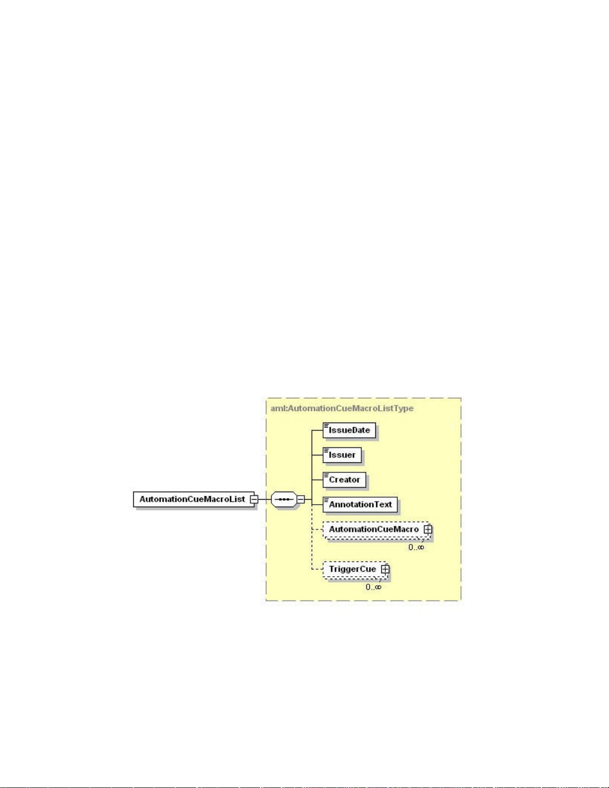
15.2 AutomationCueMacroList Structure
The AutomationCueMacroList element is illustrated in Figure 53 and the individual elements that
comprise the AutomationCueMacroList element are defined in the remaining subsections.
Figure 53: AutomationCueMacroList Structure
Dotted lines denote optional elements that can be omitted during the creation based on
Macro Editor.
DSV.OM.000391.DRM Page 55 of 68 Version 1.3
Doremi Labs
Page 56

15.2.1IssueDate Node
The IssueDate node is used to define the time and date at which the AutomationCueMacroList
XML file was issued. It is meant for display to the user.
15.2.2Issuer Node
The Issuer node contains a free-form human-readable annotation that identifies the entity that
created the AutomationCueMacroList XML file. It is meant for display to the user. The default
value generated by the Macro Editor GUI is “Doremi Cinema LLC”.
15.2.3Creator Node
The Creator node contains a free-form human-readable annotation that identifies the application
used to create the AutomationCueMacroList XML file. It is meant for display to the user.
The default value generated by the Macro Editor GUI is “CineLister Macro Editor vx.y”, where
x.y corresponds to the Macro Editor application version number used to create the file.
15.2.4AnnotationText Node
The AnnotationText element is a free-form human-readable annotation describing the
AutomationCueMacroList XML file. It is meant as a display hint to the user.
The default value generated by the Macro Editor GUI is “Generated by Doremi Labs Macro
Editor version x.y”, where x.y corresponds to the Macro Editor application version number used
to create the file.
15.2.5AutomationCueMacro Nodes
Each AutomationCueMacro element contains all the parameters associated to one Macro Cue
defined using the Macro Editor GUI presented in the previous sections.
An AutomationCueMacro element contains the subnodes presented in the sections below
(Figure 54).
Figure 54: AutomationCueMacro Structure
Dotted lines denote optional elements that can be omitted during the creation based on
Macro Editor.
15.2.5.1 Name Node
The Name element is a human-readable annotation corresponding to the name given to this
Macro Cue when it was created. It is the name chosen by the user in 7.2.1 for the field Name of
the Macro.
DSV.OM.000391.DRM Page 56 of 68 Version 1.3
Doremi Labs
Page 57

15.2.5.2 Id Node
The Id element uniquely identifies the AutomationCueMacro for asset management purposes. It
is encoded as an urn:uuid per [RFC 4122].
15.2.5.3 AnnotationText Node [optional]
This AnnotationText element is a human-readable annotation corresponding to the comment
assigned to this Macro Cue when it was created. It is the name chosen by the user in 7.2.1 for
the field Comments.
15.2.5.4 CommandList Node
The CommandList element contains a list of zero, one or more Command elements. Each
Command element corresponds to the set of parameters describing one automation individual
command composing the Macro Automation Cue.
An empty CommandList can be used to generate an Automation Cue Macro executing no
command. It will just be used to maintain portability between theaters.
15.2.6Command Node [optional]
A Command node contains the parameters associated to a specific command to be used as
part of the overall AutomationCueMacro element. These parameters depend on the type of
command defined by the Type node below (Figure 55).
Figure 55: Command Structure
Note: Dotted lines denote optional elements that can be omitted during the creation based on
Macro Editor.
DSV.OM.000391.DRM Page 57 of 68 Version 1.3
Doremi Labs
Page 58

15.2.6.1 Type Sub-Node
The available types of commands are listed below:
Table 1: Command Types Available
Type Description
Black Black video and silent audio signals will be generated by
the server
GPO A GPO will be sent by the server
Dowser The command concerns the projector dowser
Lamp The command concerns the projector lamp
Channel The command concerns the projector channel
Play The command will put the server in play mode
Pause The command will put the server in pause mode
TogglePlayPause The command will put the server in TogglePlayPause
mode
VideoOutputMode The command will set the video output mode
ProjectorMacro The command will specify a DLP projector macro
DeviceRawSendMes
The command will send a message to a device
sage
PurgePendingMacro The command will purge pending macros
Note: In case the command type is Play, Pause, TogglePlayPause or PurgePendingMacro, no
additional parameters are required within the Command element.
15.2.6.2 Duration Sub-Node [optional]
The Duration element has only to be used for the Black command type. It specifies the duration,
as a number of seconds, of the associated black video and silent audio output.
15.2.6.3 Line Sub-Node [optional]
The Line element has only to be used for the “GPO” command type. It specifies the GPO line
number to be used for the associated command. It contains an integer to be chosen between 0
and 7.
15.2.6.4 Value Sub-Node [optional]
The Value element has only to be used for GPO, Dowser, Lamp, Channel, VideoOutputMode,
and ProjectorMacro command types.
When used for the GPO command, it has to be the Value element grouped with the Line and
optional PulseDelay elements sequence. When used for the Dowser, Lamp, Channel,
VideoOutputMode, or ProjectorMacro commands, it has to be the standalone Value element
defined at the same level as the Duration element in the schema (Figure 55).
DSV.OM.000391.DRM Page 58 of 68 Version 1.3
Doremi Labs
Page 59

The format of this Value element also depends on the kind of command type. The table below
presents the usage of such elements for each command type:
Table 2: Value Formats
Type Associated Value Format Description
GPO Possible values:
- 0: means GPO OFF
- 1: means GPO ON
- 2: means GPO Pulse mode
Dowser Possible values:
- 0: means Dowser OFF
- 1: means Dowser ON
Lamp Possible values:
- 0: means Lamp OFF
- 1: means Lamp ON
Channel The Value element is an integer chosen between 0 and 16.
This integer indicates to which projector channel to switch.
VideoOutputMode Possible values:
- DolphinColorConversionDefault: default video output mode
- DolphinColorConversion444to422: video output mode
allowing playback of the corresponding 24fps Package at
48fps.
ProjectorMacro The value indicates the concerned projector macro name
15.2.6.5 PulseDelay Sub-Node [optional]
The PulseDelay element has only to be present for the “GPO” command when the associated
value is set to 2 (Pulse Mode) (Table 2). Its value is the duration, in milliseconds, during which
the associated GPO will remain ON level before going to OFF.
15.2.6.6 DeviceName Sub-Node [optional]
The DeviceName element has only to be present for the “DeviceRawSendMessage” command.
It will contain the name of the device to which the message has to be sent.
15.2.6.7 MessageType Sub-Node [optional]
The MessageType element has only to be present for the “DeviceRawSendMessage”
command. It will define the type of the message (e.g. text, binary).
15.2.6.8 Message Sub-Node [optional]
The Message element has only to be present for the “DeviceRawSendMessage” command. It
contains the actual message to be sent to the device.
DSV.OM.000391.DRM Page 59 of 68 Version 1.3
Doremi Labs
Page 60

15.2.7TriggerCue Node [optional]
Each TriggerCue element corresponds to all the parameters defining a TriggerCue. These
parameters are recorded in the sub-nodes presented in the following paragraphs (Figure 56).
Figure 56: TriggerCue Structure
Dotted lines denote optional elements that can be omitted during the creation based on
Macro Editor.
Several TriggerCue elements can be generated. They just have to be put back to back at this
XML level (Figure 53).
A TriggerCue node without CueType and CueParameter element can be used to generate a
Trigger Cue executing no command. It will just be used to maintain portability between theaters.
In such a case, the only required sub-elements are the Name and the Id element below.
15.2.7.1 Name Node
The Name element is a human-readable annotation corresponding to the name given to this
TriggerCue when it was created. It is the name chosen by the user in Figure 39 for the field
Name of the Trigger.
15.2.7.2 Id Node
The Id element uniquely identifies the TriggerCue for asset management purposes. It is
encoded as an urn:uuid per [RFC 4122].
15.2.7.3 AnnotationText Node [optional]
This AnnotationText element is a human-readable annotation corresponding to the comment
assigned to this TriggerCue when it was created. It is the name chosen by the user in Figure 39
for the field Comments.
DSV.OM.000391.DRM Page 60 of 68 Version 1.3
Doremi Labs
Page 61

15.2.7.4 CueType Node [optional]
The CueType element corresponds to the type of Cue used by the TriggerCue. The available
Cue Types are listed in the table below:
Table 3: Cue Types Available
Type Description
GPI Allows assignment of a GPI line and value to the Trigger
Signal Allows assignment of another signal to the Trigger
15.2.7.5 CueTypeParameters [optional]
The CueTypeParameters element contains the parameters associated to the Cue type defined
in the CueType element (Figure 57).
Figure 57: TriggerCue Structure
Dotted lines denote optional elements that can be omitted during the creation based on
the Macro Editor.
For GPI Cue Type, the two following parameters have to be used: Line and Value.
The Line element specifies the GPI line number to be used for the associated command. It
contains an integer to be chosen between 0 and 7.
The Value element indicates the state of the GPI: ON (Value = 1) or OFF (Value = 2).
For Signal Cue Type, the following parameter has to be used: Name.
The Name element specifies the signal name.
DSV.OM.000391.DRM Page 61 of 68 Version 1.3
Doremi Labs
Page 62

15.3 Schema
The XML Schema document presented in this paragraph defines the structure of a Macro
Automation Cue List using a machine-readable language. While this schema is intended to
faithfully represent the structure presented in the prose portions (see Section 15.2) of this
document, conflicts in definition may occur. In the event of such a conflict, the prose shall be the
authoritative expression of the structure.
<?xml version="1.0"?>
<xs:schema targetNamespace="http://www.doremilabs.com/schemas/xxx/AML"
xmlns:aml="http://www.doremilabs.com/schemas/xxx/AML"
xmlns:ds="http://www.w3.org/2000/09/xmldsig#"
xmlns:xs="http://www.w3.org/2001/XMLSchema"
elementFormDefault="qualified" attributeFormDefault="unqualified">
<xs:import namespace="http://www.w3.org/XML/1998/namespace" schemaLocation="http://www.w3.org/2001/03/xml.xsd"/>
<!-- AutomationCueMacroList -->
<xs:element name="AutomationCueMacroList" type="aml:AutomationCueMacroListType"/>
<xs:complexType name="AutomationCueMacroListType">
<xs:sequence>
<xs:element name="IssueDate" type="xs:dateTime"/>
<xs:element name="Issuer" type="aml:UserText"/>
<xs:element name="Creator" type="aml:UserText"/>
<xs:element name="AnnotationText" type="aml:UserText"/>
<xs:element name="AutomationCueMacro" type="aml:AutomationCueMacroType” minOccurs="0"
<xs:element name="TriggerCue" type="aml:TriggerCueType” minOccurs="0" maxOccurs="unbounded"/>
</xs:sequence>
</xs:complexType>
maxOccurs="unbounded"/>
<!-- AutomationCueMacro -->
<xs:complexType name="AutomationCueMacroType">
<xs:sequence>
<xs:element name="Name" type="aml:UserText"/>
<xs:element name="Id" type="aml:UUID"/>
<xs:element name="AnnotationText" type="aml:UserText" minOccurs="0"/>
<xs:element name="CommandList">
<xs:complexType>
<xs:sequence>
<xs:element name="Command" type="aml:CommandType" minOccurs="0" maxOccurs="unbounded"/>
</xs:sequence>
</xs:complexType>
</xs:element>
</xs:sequence>
</xs:complexType>
<!-- TriggerCue -->
<xs:complexType name="TriggerCueType">
<xs:sequence>
<xs:element name="Name" type="aml:UserText"/>
<xs:element name="Id" type="aml:UUID"/>
<xs:element name="AnnotationText" type="aml:UserText" minOccurs="0"/>
<xs:element name="CueType" type="aml:UserText" minOccurs="0"/>
<xs:element name="CueTypeParameters" type="aml:CueTypeParametersType" minOccurs="0"/>
</xs:sequence>
</xs:complexType>
DSV.OM.000391.DRM Page 62 of 68 Version 1.3
Doremi Labs
Page 63

<!-- CueTypeParameters -->
<xs:complexType name="CueTypeParametersType">
<xs:choice>
<xs:sequence>
<xs:element name="Line" type="xs:long"/>
<xs:element name="Value" type="aml:UserText”/>
</xs:sequence>
<xs:element name="Name" type="aml:UserText"/>
</xs:choice>
</xs:complexType>
<!-- Command -->
<xs:complexType name="CommandType">
<xs:sequence>
<xs:element name="Type" type="aml:UserText"/>
<xs:choice minOccurs="0">
<xs:sequence>
<xs:element name="Line" type="xs:long"/>
<xs:element name="Value" type="aml:UserText"/>
<xs:element name="PulseDelay" type="aml:UserText" minOccurs="0"/>
</xs:sequence>
<xs:element name="Value" type="aml:UserText"/>
<xs:element name="Duration" type="xs:long"/>
<xs:sequence>
<xs:element name="DeviceName" type="aml:UserText"/>
<xs:element name="MessageType" type="aml:UserText"/>
<xs:element name="Message" type="aml:UserText"/>
</xs:sequence>
</xs:choice>
</xs:sequence>
</xs:complexType>
<!-- UUID -->
<xs:simpleType name="UUID">
<xs:restriction base="xs:anyURI">
<xs:pattern value="urn:uuid:[0-9a-fA-F]{8}-[0-9a-fA-F]{4}-[0-9a-fA-F]{4}-[0-9a-fA-F]{4}-[0-9a-fA-F]{12}"/>
</xs:restriction>
</xs:simpleType>
<!-- UserText -->
<xs:complexType name="UserText">
<xs:simpleContent>
<xs:extension base="xs:string">
<xs:attribute name="language" type="xs:language" use="optional" default="en"/>
</xs:extension>
</xs:simpleContent>
</xs:complexType>
</xs:schema>
DSV.OM.000391.DRM Page 63 of 68 Version 1.3
Doremi Labs
Page 64

15.4 XML Diagram Legend
The following provides a legend for notation used in diagrams depicting XML structures.
15.4.1Element symbols
In the schema design diagrams presented above in this document, only the elements are
drawn. Attributes are not visible. The cardinality of the element (0..1, 1 exactly, 0..n, 1..n) is
indicated by the border of the elements. Optional elements are drawn with a dashed line,
required elements with a solid line. A maximum occurrence greater one is indicated by a double
border.
The content model of elements is symbolized on the left and right side of the element boxes.
The left side indicates whether the element contains a simple type (text, numbers, dates, etc.) or
a complex type (further elements). The right side of the element symbol indicates whether it
contains child elements or not:
15.4.1.1 Examples
Optional single element without child elements. Minimum Occurrence = 0, Maximum
Occurrence = 1, content = complex.
As above, but with child elements. The plus at the right side indicates the presence of one or
more undisplayed child elements.
Mandatory single element. Minimum Occurrence = 1, Maximum Occurrence = 1, content =
complex, no child elements (i.e., this denotes an empty element). The gray or green text below
the element displays the xml-schema annotation associated with the element.
Mandatory multiple element containing child elements (content = complex). This element must
occur at least once (Minimum Occurrence = 1) and may occur as often as desired (Maximum
Occurrence = unbounded).
Mandatory single element with containing simple content (e.g. text) or mixed complex content
(e.g. text with xhtml markup). Minimum Occurrence = 1, Maximum Occurrence = 1, type =
DSV.OM.000391.DRM Page 64 of 68 Version 1.3
Doremi Labs
Page 65

xsd:string (for example), content = simple. The three lines in the upper left corner are used for
both text and numeric content.
15.4.2Model symbols ("compositors")
A sequence of elements. The elements must appear exactly in the sequence in which they
appear in the schema diagram.
A choice of elements. Only a single element from those in the choice may appear at this
position.
The all model, in which the sequence of elements is not fixed.
15.5 Types
If an element refers to a complex global type, the type is shown with a border and yellow
background. You can click on the gray type name shown at the top to jump to the type definition
itself.
Depending on the settings in xml spy when generating the schema diagrams, the type name
may be shown in the line below the element name:
In that case, the type names of simple types are shown as well:
DSV.OM.000391.DRM Page 65 of 68 Version 1.3
Doremi Labs
Page 66

15.6 Model groups and references
An element group is a named container with one or several elements. The group of elements
can be reused at multiple places in the schema. Model groups are invisible in the instance
document (in contrast to types, which require). Model groups have been used sparingly since
they do not map to a feature in object-oriented programming languages (unless they support
multiple inheritance).
Import note on reading the diagrams for model groups: If the model group symbol is drawn with
simple lines (i.e. not dashed), this does not imply that the elements in the model group are
required. The optionality of the group depends on the optionality of elements contained in the
model group. (Model groups can be made optional, e.g. to make a model group with required
elements optional in some cases, but this has not been used.)
The any group is a special kind of model group. It is a placeholder for elements not defined in
the schema. The "any" element defines points where the schema can be extended. After the
"Any" keyword, the namespace from which the elements may come is defined. For example,
"##other" specifies that the extension elements may come from any namespace, except from
the current schema namespace.
Element references are indicated through a link arrow in the lower left corner. They are similar
to references to model groups within a schema, but instead of refining the model group, they
directly refer to a single global element. The global element can then be reused in multiple
places.
DSV.OM.000391.DRM Page 66 of 68 Version 1.3
Doremi Labs
Page 67

16 Acronyms
Term Definition
FPS Frames Per Second
GPI General Purpose Input
GPO General Purpose Output
HDD Hard Disk Drive
LCD Liquid Crystal Display
LED Light Emitting Diode
LTC Linear Timecode
RAID Redundant Array of independent Disks
SDI Serial Digital Interface
SPL Show Play List
VGA Video Graphics Array
DSV.OM.000391.DRM Page 67 of 68 Version 1.3
Doremi Labs
Page 68

17 Document Revision History
Date Version Description
03/17/2009 1.0 First version.
07/26/2012 1.1 Logo updated and contact information added.
08/29/2013 1.2 Section 6.1 updated and minor corrections made throughout.
05/05/2014 1.3 Minor editorial changes made.
DSV.OM.000391.DRM Page 68 of 68 Version 1.3
Doremi Labs
 Loading...