

Page 1

DCP-2000 and DCP-2K4
Digital Cinema Servers
User Manual
Version 1.5
The English version of this document is the only legally binding
version. Translated versions are not legally binding and are for
convenience only.
____________________________________________________________________________________
D2K.OM.001822.DRM Page 1 of 177 Version 1.5
Doremi Labs
Page 2

Table of Contents
1 INTRODUCTION...........................................................................................................................8
1.1 PURPOSE................................................................................................................................... 8
1.2 SOFTWARE VERSION................................................................................................................... 8
1.3 CONTACT INFORMATION...............................................................................................................8
2 OVERVIEW...................................................................................................................................9
2.1 FRONT PANEL............................................................................................................................ 9
2.1.1 DCP-2000 Front Panel......................................................................................................9
2.1.2 DCP-2K4 Front Panel..................................................................................................... 10
3 CINELISTER............................................................................................................................... 11
3.1 PASSWORDS............................................................................................................................ 12
4 NETWORK CONFIGURATION................................................................................................... 13
4.1 DEFAULT NETWORK CONFIGURATION........................................................................................... 13
4.2 CHANGING THE IP ADDRESS......................................................................................................13
4.3 NETWORK RESTART ................................................................................................................. 14
5 TIME ZONE CONFIGURATION.................................................................................................. 15
5.1 CHECKING THE TIME ZONE........................................................................................................ 15
5.2 CHANGING THE TIME ZONE.......................................................................................................16
6CONTROL PANEL....................................................................................................................... 17
6.1 ACCOUNT MANAGER GUI..........................................................................................................18
6.1.1 Add a New User Account................................................................................................ 19
6.1.2 Edit an Existing User Account......................................................................................... 21
6.1.3 Delete an Existing User Account.....................................................................................22
6.2 AUDIO CONFIGURATION.............................................................................................................. 22
6.2.1 Channel Mapping Tab..................................................................................................... 24
6.2.1.1 Disabled Configuration..............................................................................................24
6.2.1.2 Pre-Defined Mapping Configurations........................................................................24
6.2.1.2.1 4 Channels......................................................................................................... 24
6.2.1.2.2 6 Channels......................................................................................................... 26
6.2.1.2.3 7 Channels......................................................................................................... 27
6.2.1.2.4 8 Channels......................................................................................................... 28
6.2.1.2.5 9 Channels......................................................................................................... 29
6.2.1.2.6 ISDCF................................................................................................................ 30
6.2.1.3 Custom Mapping Configuration.................................................................................32
6.2.2 Advanced Tab................................................................................................................. 33
6.2.3 SMPTE Packages........................................................................................................... 34
6.2.4 Interop Packages............................................................................................................ 34
6.3 CONTENT FEED MANAGER.........................................................................................................35
6.3.1 Quick Configuration........................................................................................................ 35
6.3.2 Scan for Server............................................................................................................... 36
6.3.3 Advanced Options Button............................................................................................... 38
6.3.4 Adding a Server Manually............................................................................................... 39
6.3.4.1 Networking the Server(s).......................................................................................... 39
6.3.5 Advanced Options........................................................................................................... 41
6.3.6 Deleting a Server............................................................................................................ 42
______________________________________________________________________________________
D2K.OM.001822.DRM Page 2 of 177 Version 1.5
Doremi Labs
Page 3

6.3.7 Ingesting from a Server that was Added........................................................................ 42
6.4 CONTENT MANAGER.................................................................................................................. 44
6.4.1 Home Page..................................................................................................................... 45
6.4.2 Composition Playlists Page............................................................................................. 47
6.4.2.1 Actions Button...........................................................................................................47
6.4.2.2 Info Button................................................................................................................ 53
6.4.2.2.1 Properties Tab....................................................................................................53
6.4.2.2.2 Assets Tab ........................................................................................................ 54
6.4.2.2.3 SPL(s) Tab......................................................................................................... 55
6.4.2.2.4 KDM(s) Tab........................................................................................................58
6.4.3 Search Tool................................................................................................................... 61
6.4.4 Decryption Keys Page.................................................................................................... 62
6.4.5 Performing a KDM Sanity Check ................................................................................... 64
6.4.6 Show Playlists Page....................................................................................................... 66
6.4.6.1 Delete an SPL...........................................................................................................66
6.4.6.2 Export an SPL...........................................................................................................66
6.4.7 Information Button........................................................................................................... 67
6.4.8 Licenses Page................................................................................................................ 67
6.4.9 Delete a License............................................................................................................. 68
6.5 DEVICE CONTROLLER................................................................................................................ 69
6.6 DEVICE MANAGER..................................................................................................................... 69
6.6.1 Adding a Projector.......................................................................................................... 69
6.6.2 Removing a Device or Projector.....................................................................................71
6.6.3 Automation Libraries Management................................................................................. 72
6.6.4 Adding an eCNA Device................................................................................................. 72
6.6.4.1 Removing an eCNA Device...................................................................................... 73
6.6.5 Adding a JNior Device.................................................................................................... 73
6.6.5.1 Removing a JNior Device..........................................................................................74
6.6.6 Adding a Raw Device...................................................................................................... 74
6.6.7 Removing a Raw Device................................................................................................. 75
6.6.8 Adding a Serial Device ...................................................................................................75
6.6.9 ISE1 Device.................................................................................................................... 78
6.6.10 CSS Device.................................................................................................................. 78
6.6.11 3D Configuration........................................................................................................... 78
6.6.11.1 Dolby 3D Support....................................................................................................78
6.6.11.2 RealD 3D Support...................................................................................................78
6.6.11.3 Sensio 3D Support..................................................................................................80
6.6.12 Closed Caption Support................................................................................................ 80
6.6.13 Subtitle Engine Configuration........................................................................................ 80
6.7 DIAGNOSTIC TOOL.................................................................................................................... 82
6.8 LANGUAGE SETUP..................................................................................................................... 83
6.9 LICENSE MANAGER................................................................................................................... 86
6.9.1 Adding a License............................................................................................................ 86
6.10 LIVE MANAGER....................................................................................................................... 89
6.10.1 Creating a Live Event.................................................................................................... 90
6.10.2 Deleting a Live CPL...................................................................................................... 92
6.11 LOG MANAGER.......................................................................................................................93
6.11.1 Log Manager Configuration .......................................................................................... 94
6.12 LOG OPERATOR MANAGER....................................................................................................... 95
6.12.1 Exporting System Logs............................................................................................... 100
6.13 NETWORKING CONFIGURATION................................................................................................ 104
______________________________________________________________________________________
D2K.OM.001822.DRM Page 3 of 177 Version 1.5
Doremi Labs
Page 4

6.14 TIME SETTING...................................................................................................................... 104
6.15 TOUCHSCREEN CALIBRATION.................................................................................................. 104
7 INGEST MANAGER GUI..........................................................................................................106
7.1 INGESTING CONTENT...............................................................................................................106
7.2 CONTENT TYPES.....................................................................................................................106
7.3 INGESTING CONTENT ..............................................................................................................108
7.3.1 Ingesting content From a USB Drive............................................................................108
7.4 INGESTING CONTENT FROM A REMOTE DOREMI SERVER/LMS......................................................109
7.4.1 File Transfer Protocol (FTP)..........................................................................................109
7.4.1.1 Ingesting Content From a Doremi Remote Server/LMS..........................................109
7.5 INGEST PROGRESS..................................................................................................................110
7.6 PNGEST ................................................................................................................................ 111
7.6.1 How to Pngest a CPL.................................................................................................... 111
8 SHOW MANAGEMENT USING CINELISTER..........................................................................113
8.1 CINELISTER EDITOR TAB......................................................................................................... 113
9 SHOW PLAYLISTS .................................................................................................................. 115
9.1 AUDIO-VISUAL CONTENT..........................................................................................................115
9.2 SHOW PLAYLIST CREATION...................................................................................................... 117
9.2.1 How to Create a New Show Playlist..............................................................................117
9.2.2 Element Re-Ordering.................................................................................................... 118
9.2.2.1 Refresh Button........................................................................................................118
9.2.2.2 Save Button ........................................................................................................... 118
9.3 EXPORT SHOW PLAYLIST ........................................................................................................ 119
9.3.1 How to Save and Export a Show Playlist...................................................................... 119
9.4 IMPORTING A SHOW PLAYLIST................................................................................................... 120
9.4.1 How to Import an SPL .................................................................................................. 120
10 ELEMENT PROPERTIES......................................................................................................121
10.1 UNENCRYPTED CPL'S...........................................................................................................122
10.2 ENCRYPTED CPL WITH KDM VALID (MORE THAN 48 HOURS)...................................................123
10.3 ENCRYPTED CPL WITH KDM VALID (LESS THAN 48 HOURS)......................................................124
10.4 DELETING A CPL FROM THE SERVER......................................................................................125
11 PLAY 2D CONTENT IN 3D MODE........................................................................................126
11.1 3D MODE CONFIGURATION................................................................................................... 126
11.1.1 How to Set the Show Playlist Mode to 3D...................................................................126
12 ACCESSING A SHOW PLAYLIST.........................................................................................128
12.1 EDITING AN EXISTING SHOW PLAYLIST.....................................................................................129
12.2 DELETING A SHOW PLAYLIST.................................................................................................. 130
13 AUTOMATION CUES............................................................................................................. 131
13.1 MACRO AUTOMATION CUES....................................................................................................131
13.2 MACRO CREATION USING MACRO EDITOR............................................................................... 131
13.3 EDITING A MACRO AUTOMATION CUE..................................................................................... 133
13.4 INSERTING ACTIONS INTO MACRO CUES..................................................................................134
13.4.1 Add a GPO Action to the Macro Automation Cue.......................................................136
13.4.2 Playback Action Insertion............................................................................................137
13.4.3 Video Output Action Insertion..................................................................................... 138
______________________________________________________________________________________
D2K.OM.001822.DRM Page 4 of 177 Version 1.5
Doremi Labs
Page 5

13.4.4 Dowser Action Insertion.............................................................................................. 138
13.4.5 Projector Channel Switch Insertion............................................................................. 139
13.5 AUTOMATION LIBRARY USAGE................................................................................................ 140
13.5.1 Using Automation Library............................................................................................140
13.5.2 Resulting Macro Setting.............................................................................................. 141
13.5.3 Action List Management.............................................................................................142
13.5.3.1 Action Re-Ordering.............................................................................................. 142
13.5.3.2 Action Edition........................................................................................................142
13.5.3.3 Action Removal.....................................................................................................142
13.5.4 Macro Saving.............................................................................................................. 142
14 TRIGGER CUE TAB............................................................................................................... 143
14.1 TRIGGER CUE TAB OVERVIEW................................................................................................ 143
14.2 TRIGGER CUE CREATION.......................................................................................................144
14.2.1 Connection to an Event............................................................................................... 145
14.2.2 Connection to a Signal Event...................................................................................... 146
14.3 TRIGGER CUE SAVING........................................................................................................... 147
14.4 PRE-DEFINED MACRO USAGE............................................................................................... 148
14.5 DEFAULT CUES.................................................................................................................... 148
14.6 STARTUP SCRIPTS...............................................................................................................148
15 ADD A TRIGGER CUE TO A SHOW PLAYLIST.................................................................... 149
15.1 ADD A TRIGGER CUE FOR ONE ELEMENT OF THE SHOW PLAYLIST..............................................150
16 CINELISTER PLAYBACK TAB..............................................................................................151
16.1 PLAYBACK AN EXISTING SPL.................................................................................................. 151
16.2 PLAYBACK PROGRESS ......................................................................................................... 153
16.3 PAUSE MODE....................................................................................................................... 154
16.4 ADJUSTING THE DEFAULT VALUES...........................................................................................155
16.5 PLAYBACK OF A LIVE EVENT ..................................................................................................157
16.5.1 How to Add a Live Event CPL.....................................................................................157
16.5.2 How to Create and Play an SPL Using a Live Event CPL...........................................157
16.6 PLAYBACK LOCK MODE........................................................................................................159
16.7 PLAYBACK ALERT MESSAGES................................................................................................ 160
17 CINELISTER SCHEDULE TAB..............................................................................................162
17.1.1 How to Schedule Playback......................................................................................... 162
17.2 SCHEDULE PLAYBACK MESSAGES..........................................................................................164
17.2.1 Schedule Conflict........................................................................................................ 164
17.2.2 Scheduled Show Did Not Start Error...........................................................................165
17.2.3 Show Playlist Removal............................................................................................... 165
17.3 PLAYBACK RECOVERY DUE TO POWER FAILURE......................................................................166
17.3.1 How to Recover Playback........................................................................................... 166
17.4 SHUTTING DOWN DURING PLAYBACK......................................................................................167
18 CONTROL TAB...................................................................................................................... 168
18.1 DOWNLOAD THE FILE FROM THE FTP...................................................................................... 168
18.2 CONFIGURING THE CONTROL TAB............................................................................................168
18.2.1 Configuration Example................................................................................................ 169
18.2.2 Basic Example of controlview.xml File........................................................................ 171
19 VIRTUAL KEYBOARD............................................................................................................ 173
______________________________________________________________________________________
D2K.OM.001822.DRM Page 5 of 177 Version 1.5
Doremi Labs
Page 6

19.1 HOW TO ACCESS THE VIRTUAL KEYBOARD............................................................................... 173
20 TIME ADJUSTMENT............................................................................................................... 174
20.1 HOW TO ADJUST THE SYSTEM TIME.......................................................................................174
21 ACRONYMS............................................................................................................................ 176
22 DOCUMENT REVISION HISTORY.........................................................................................177
______________________________________________________________________________________
D2K.OM.001822.DRM Page 6 of 177 Version 1.5
Doremi Labs
Page 7
Software License Agreement
The software license agreement can be found at the following location:
http://www.doremilabs.com/support/cinema-support/cinema-warranties/
Hardware Warranty
The hardware warranty can be found at the following location:
http://www.doremilabs.com/support/cinema-support/cinema-warranties/
China Compulsory Certification (CCC)
该产品仅适用于海拔2000 米以下地区
该产品仅适用于非热带地区
声 明
此为A 级产品,在生活环境中,该产品可能会造成无线电干扰。在这种情况下,可能需要用户对其干扰采取切实
可行的措施。
DCP-2000 KC EMC Statement
사용자안내문
(User Information)
기 종 별 사 용 자 안 내 문
A 급 기기
(업무용
방송통신기자재)
Class A Equipments (Broadcasting and communication equipments for office work)
Seller and user shall be noticed that this equipment is suitable for electromagnetic equipments
for office work (Class A) and it can be used outside home.
이 기기는 업무용(A 급) 전자파적합기기로서
판매자 또는 사용자는 이 점을 주의하시기
바라며 , 가정외의 지역에서 사용하는 것을
목적으로 합니다.
______________________________________________________________________________________
D2K.OM.001822.DRM Page 7 of 177 Version 1.5
Doremi Labs
Page 8

1 Introduction
1.1 Purpose
This manual is intended to guide the user through the use of the DCP-2000 and DCP-2K4. It also
contains information on how to properly use the CineLister application.
1.2 Software Version
This manual is for use with software version 2.4.x and higher.
1.3 Contact Information
If in need of help or assistance, please contact Doremi Labs Technical Services:
USA
24/7 Technical Services line: + 1-866-484-4004
Technical Services Email: cinemasupport@doremilabs.com
Europe
24/7 Technical Services line: + 33 (0) 492-952-847
Technical Services Link: http://support.doremitechno.org/ticketing
Japan
Technical Services line: + 044-966-4855
Technical Services Email: support@doremilabs.co.jp
Australia ~ China ~ India ~ Indonesia ~ Korea ~ Malaysia ~ New Zealand ~ Philippines ~
Singapore ~ Taiwan ~ Thailand
Technical Services Email: supportasia@doremilabs.com
______________________________________________________________________________________
D2K.OM.001822.DRM Page 8 of 177 Version 1.5
Doremi Labs
Page 9
2 Overview
The DCP-2000 and DCP-2K4 are high quality DCI JPEG-2000 servers capable of playing movie or
trailer packages in MXF format at up to 250Mbits/sec. The DCP-2000 and DCP-2K4 also support
MPEG2 Interop movies, pre-show, and alternative content playback.
2.1 Front Panel
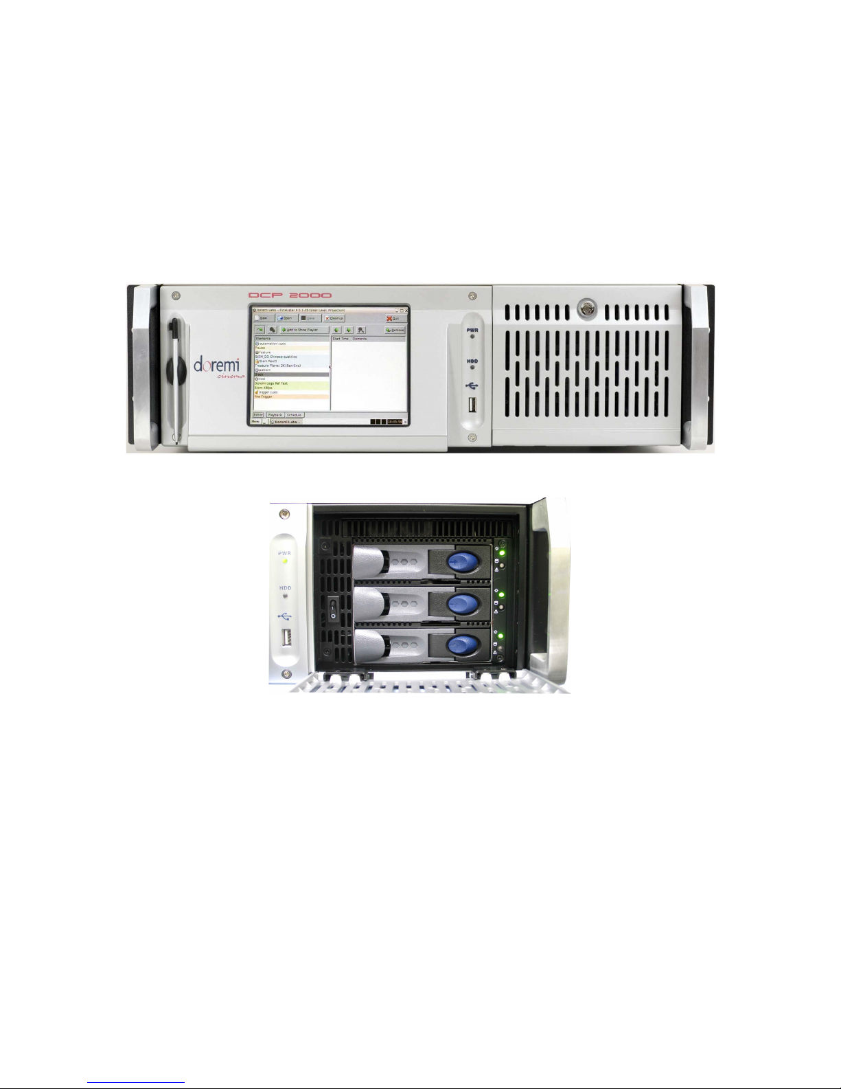
2.1.1 DCP-2000 Front Panel
• A DCP-2000 front panel with an LCD screen is shown below:
Figure 1: DCP-2000
______________________________________________________________________________________
D2K.OM.001822.DRM Page 9 of 177 Version 1.5
Figure 2: DCP-2000 HDD Cage
Doremi Labs
Page 10
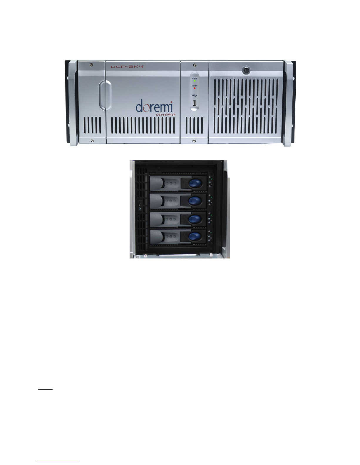
2.1.2 DCP-2K4 Front Panel
• A DCP-2K4 front panel is shown below:
Figure 3: DCP-2K4 Front Panel
Figure 4: DCP-2K4 HDD Cage
• POWER (PWR): The LED lights turn green when the unit is powered on.
• HDD: Red LED light indicate access to the Hard Disk Drives.
• The door on the right on both types of units covers the "POWER" switch and the hard disks
that make up the RAID5 storage.
• Each hard disk drive has a blue button that allows removal of the drive from the chassis.
• Be careful not to remove the hard disk drive when the DCP-2000 or DCP-2K4 is running.
• There is one USB 2.0 connector on the center of the front panel that can accommodate an
external hard drive as well as a mouse or keyboard.
• The left side of the DCP-2000 front panel contains an LCD screen.
• On the DCP-2000 front panel, the LCD can be turned on or off by pressing on the LCD
power button using the stylus attached to the front panel. This button is located behind the
stylus (Figure 1).
Note: The use of the LCD screen requires that the two rear panel VGA connectors are linked using
the VGA cable provided with the DCP-2000.
______________________________________________________________________________________
D2K.OM.001822.DRM Page 10 of 177 Version 1.5
Doremi Labs
Page 11
3 CineLister
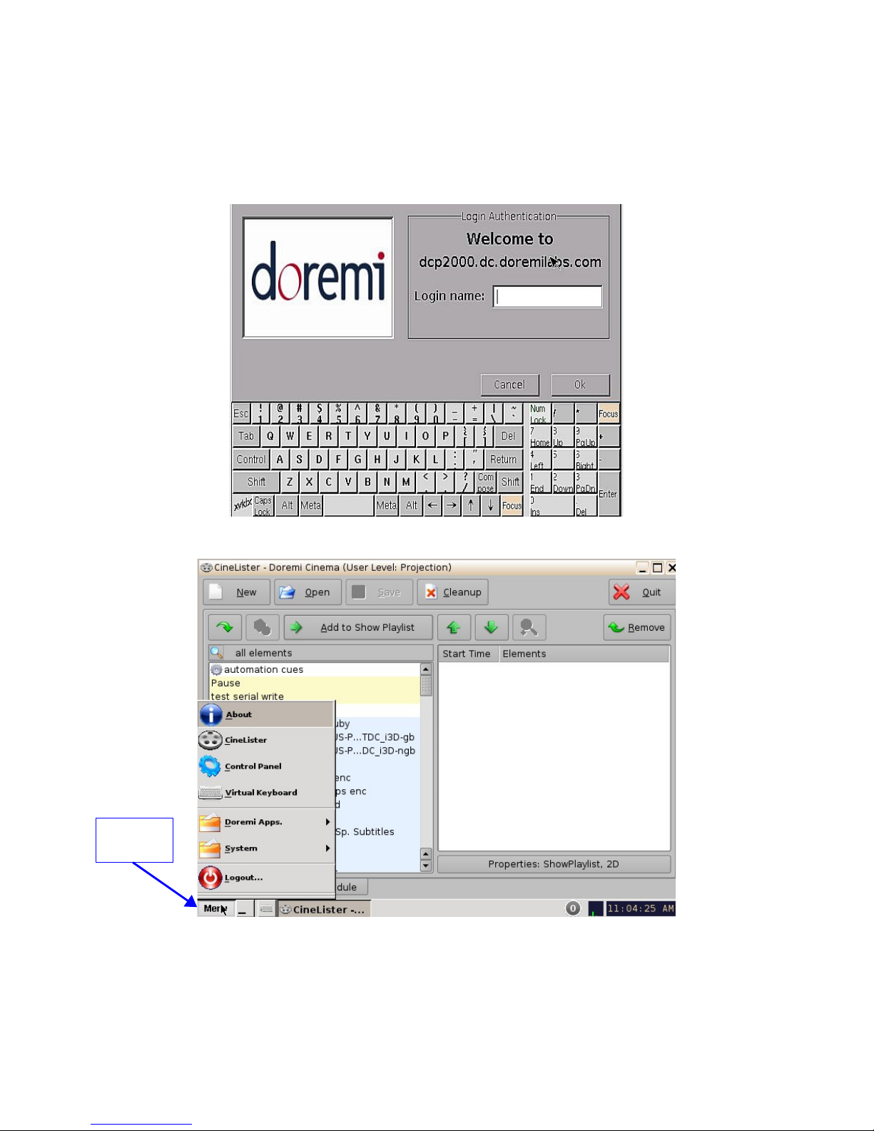
Every time the user logs out of the CineLister application and then logs back in again, a “Login
Authentication” window will appear (Figure 5). The default login name is “doremi” and the
Password is “doremi.” However, the administrator may have changed and or added other login
usernames and passwords. Please contact the administrator for the password.
Menu
Button
Figure 5: Login Authentication Window
Figure 6: CineLister Application and Menu List
______________________________________________________________________________________
D2K.OM.001822.DRM Page 11 of 177 Version 1.5
Doremi Labs
Page 12
• The CineLister application will appear every time the unit is turned on or rebooted. The
Menu button is where users can access various applications as well as the Control Panel
(Figure 6).
3.1 Passwords
You will be prompted to enter a password for various tasks when using the CineLister application.
Your administrator determines the level of security.
Note: Please contact your administrator for passwords.
The following are types of passwords you may be asked for:
• Admin (Administrator)
• Manager
• Root
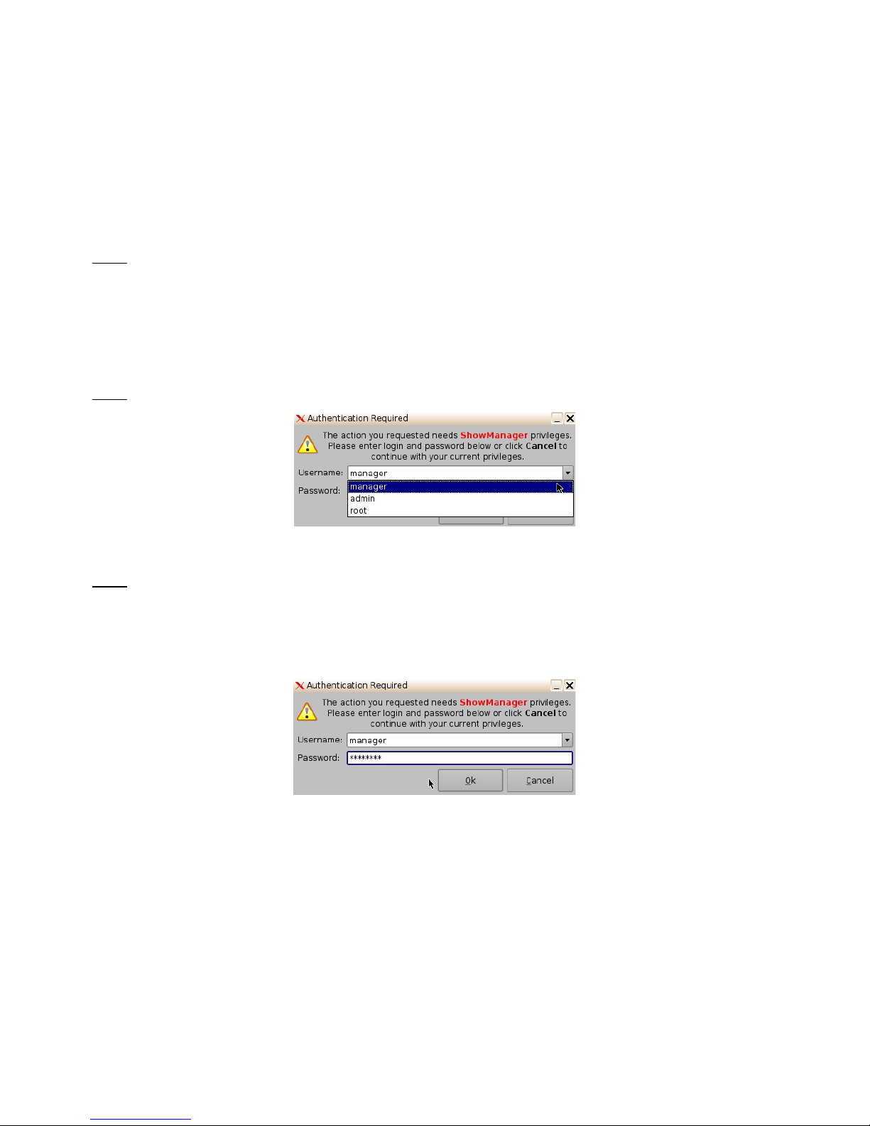
Note: In Figure 7 the user is asked to verify the username and password.
Figure 7: Password Confirmation Window
Note: The server will prompt you to the type of password that is needed for a certain task. For
example, the authentication required in the window below is “ShowManager” privileges, hence the
server will automatically prompt you to the “Manager” username. However, you can also select a
different username from the drop-down list as shown in Figure 7 above, depending on the level of
security that your administrator has provided for you.
Figure 8: Password Confirmation Window - Manager Username
______________________________________________________________________________________
D2K.OM.001822.DRM Page 12 of 177 Version 1.5
Doremi Labs
Page 13
4 Network Configuration
4.1 Default Network Configuration
All servers are shipped with a default IP address of 192.168.100.50 on the Ethernet port (Eth1) and
a DHCP assigned dynamic IP address on the Ethernet port (Eth0).
4.2 Changing the IP Address
• To change the IP address of the server, select Menu → System → Networking
Configuration and then follow the steps below:
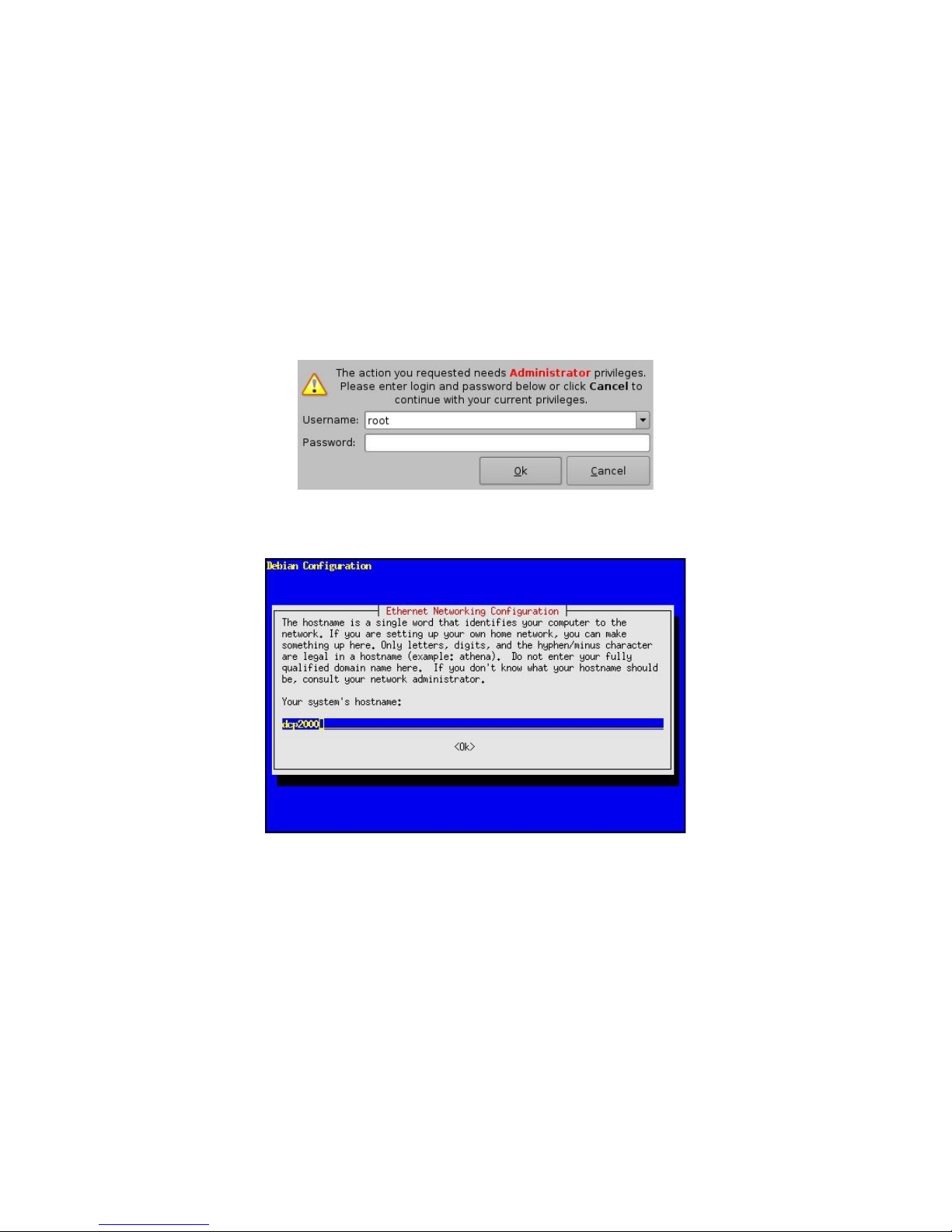
• A window will appear asking for a password as illustrated below:
Figure 9: Password Confirmation Window
• Follow the steps according to the "Ethernet Networking Configuration" Wizard.
• Press Enter to confirm the configuration of each page of the "Ethernet Networking
Configuration" Wizard. Press "Tab" to select an option.
• Enter the desired system’s hostname and then press Enter (Note: It is a good idea to put
the circuit location/screen number in here. For example, “AMC_bir_scr1,” as it will be easier
to identify when connecting via VNC and in the logs).
• Enter the desired system domain name and then press Enter.
• Select Yes to set eth0 and then press Enter.
• Select No for Removable Device and then press Enter.
• Select No for automatically configure device with DHCP and then press Enter.
______________________________________________________________________________________
D2K.OM.001822.DRM Page 13 of 177 Version 1.5
Figure 10: Network Configuration
Doremi Labs
Page 14

• Enter the desired IP address for eth0 and then press Enter.
• Enter the desired default gateway or leave empty and then press Enter.
• Enter the desired subnet mask and then press Enter.
• Select Yes to configure eth1 and then press Enter.
• Select No for Removable device and then press Enter.
• Select No for automatically configure device with DHCP and then press Enter.
• Enter the IP address of eth1 and select OK – in the example, enter 192.168.100.50 and
then press Enter.
Note: Do not put leading zeros (0) in front of any numbers. For example, do not input
0192.168.100.50.
• Enter the desired default gateway or leave empty and then press Enter.
• Enter the desired subnet mask and select OK – in our example, enter the same subnet
mask as the projector: 255.255.255.0 and then press Enter.
• Enter the IP Address of the System's Domain Name Server (or leave empty) and then
press Enter to exit the wizard.
• To verify the setup, go to Menu → Doremi Apps. → Diagnostic Tool and verify the IP
Address under the Diagnostic Tool System Tab.
4.3 Network Restart
If for any reason the network needs to be restarted, use the terminal command line below:
• Type: /etc/init.d/networking restart <Enter>
______________________________________________________________________________________
D2K.OM.001822.DRM Page 14 of 177 Version 1.5
Doremi Labs
Page 15
5 Time Zone Configuration
Units are by default set to Pacific Time Zone (PST or PDT). This section provides information on
how to check and/or change the time zone.
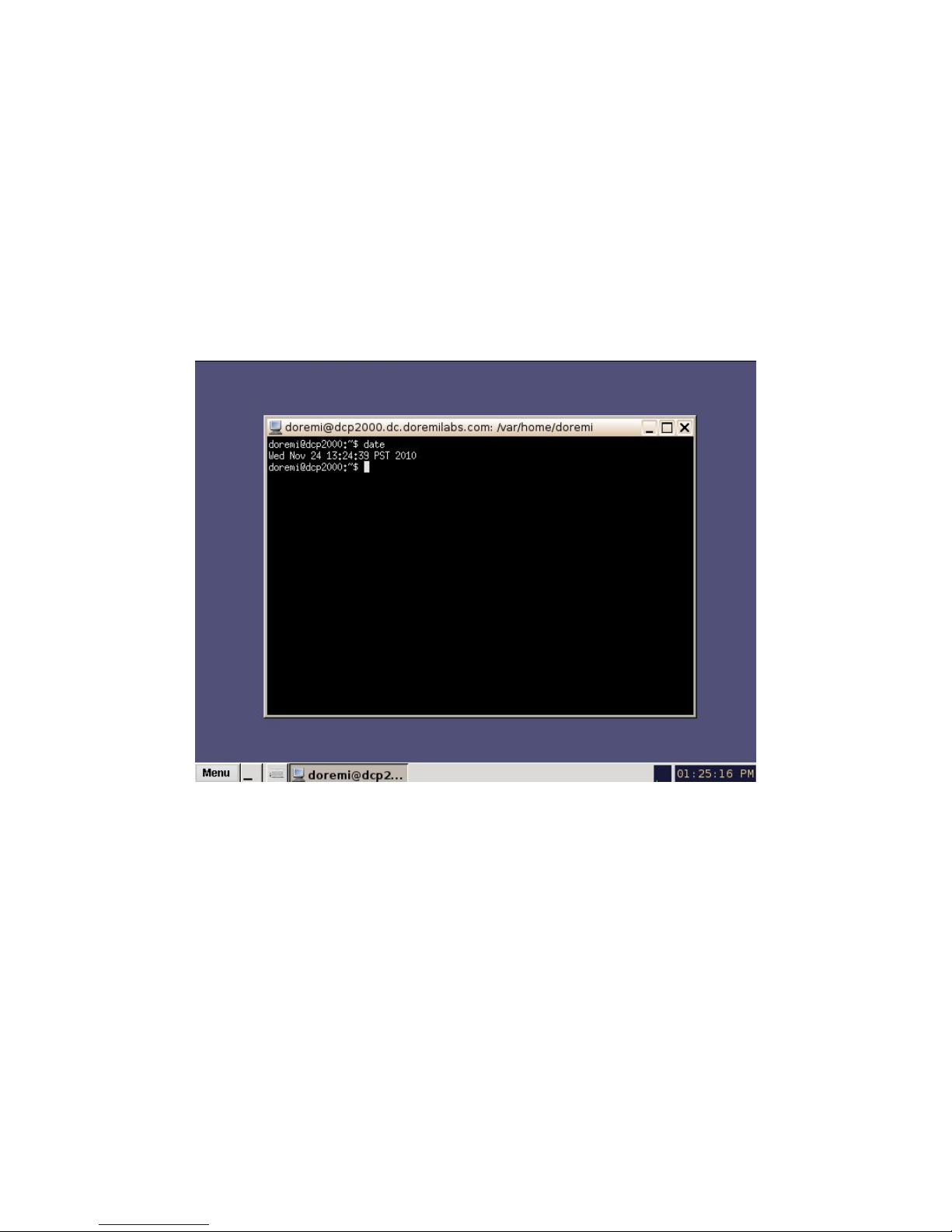
5.1 Checking the Time Zone
• To confirm that the time zone of the unit is set correctly, open a terminal window by going to
the “Menu → System → Terminal” menu.
• Type: date and then press Enter.
• The current date, time, and time zone will be displayed (Figure 11).
Figure 11: Terminal Window with Date Displayed
______________________________________________________________________________________
D2K.OM.001822.DRM Page 15 of 177 Version 1.5
Doremi Labs
Page 16
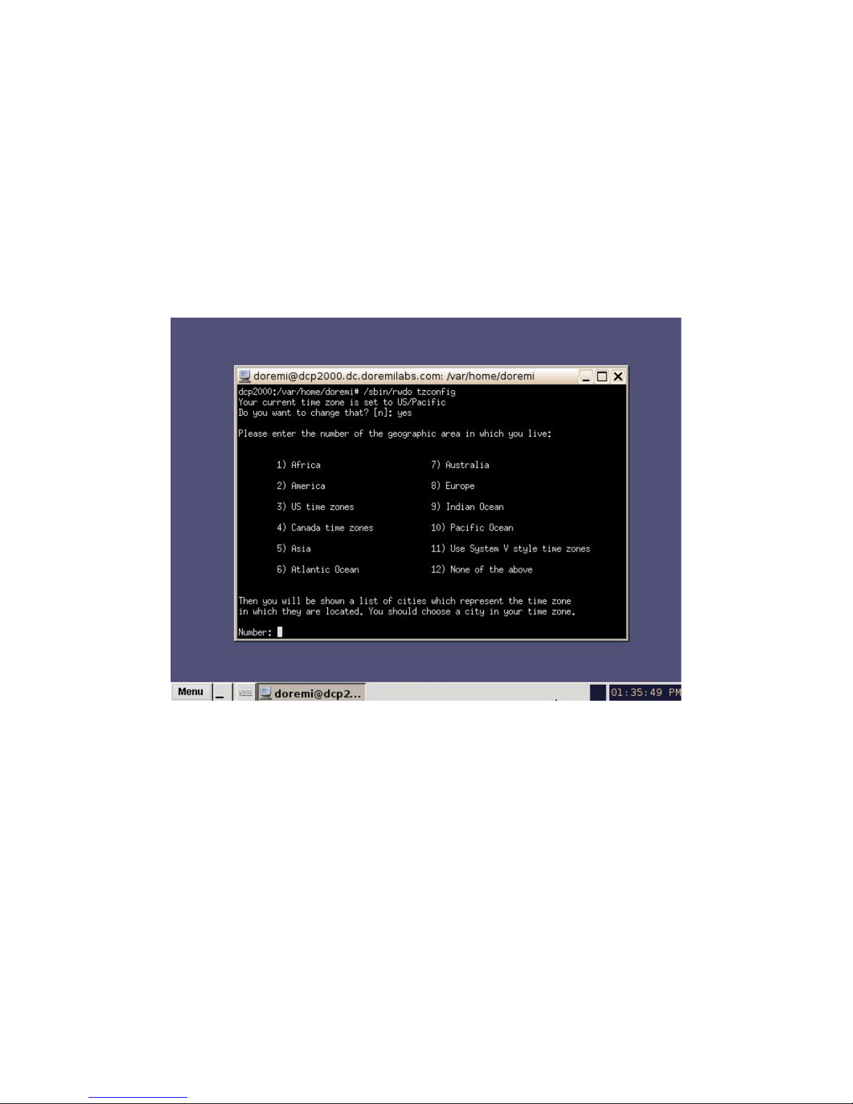
5.2 Changing the Time Zone
• To change the time zone, follow the steps below in the terminal window
(Menu/System/Terminal):
• Type: su and then press Enter.
• Type the "root" password to log in as "root" – consult the system administrator to receive
the root password or Doremi to know the default root password.
• Type: rwdo tzconfig and then press Enter.
• Type: Yes (to confirm the change).
• Select the number of the geographic area for the time change (Figure 12).
Figure 12: Terminal Window with Time Zone Wizard
• Once the geographic area number has been selected, press Enter.
• Type the name of the city / region that you would like the time zone set to (e.g., Singapore,
Caribbean, PST, etc.).
• Press Enter.
• After typing the city / region, the unit will now be set to the desired configuration.
• Exit the terminal window.
______________________________________________________________________________________
D2K.OM.001822.DRM Page 16 of 177 Version 1.5
Doremi Labs
Page 17
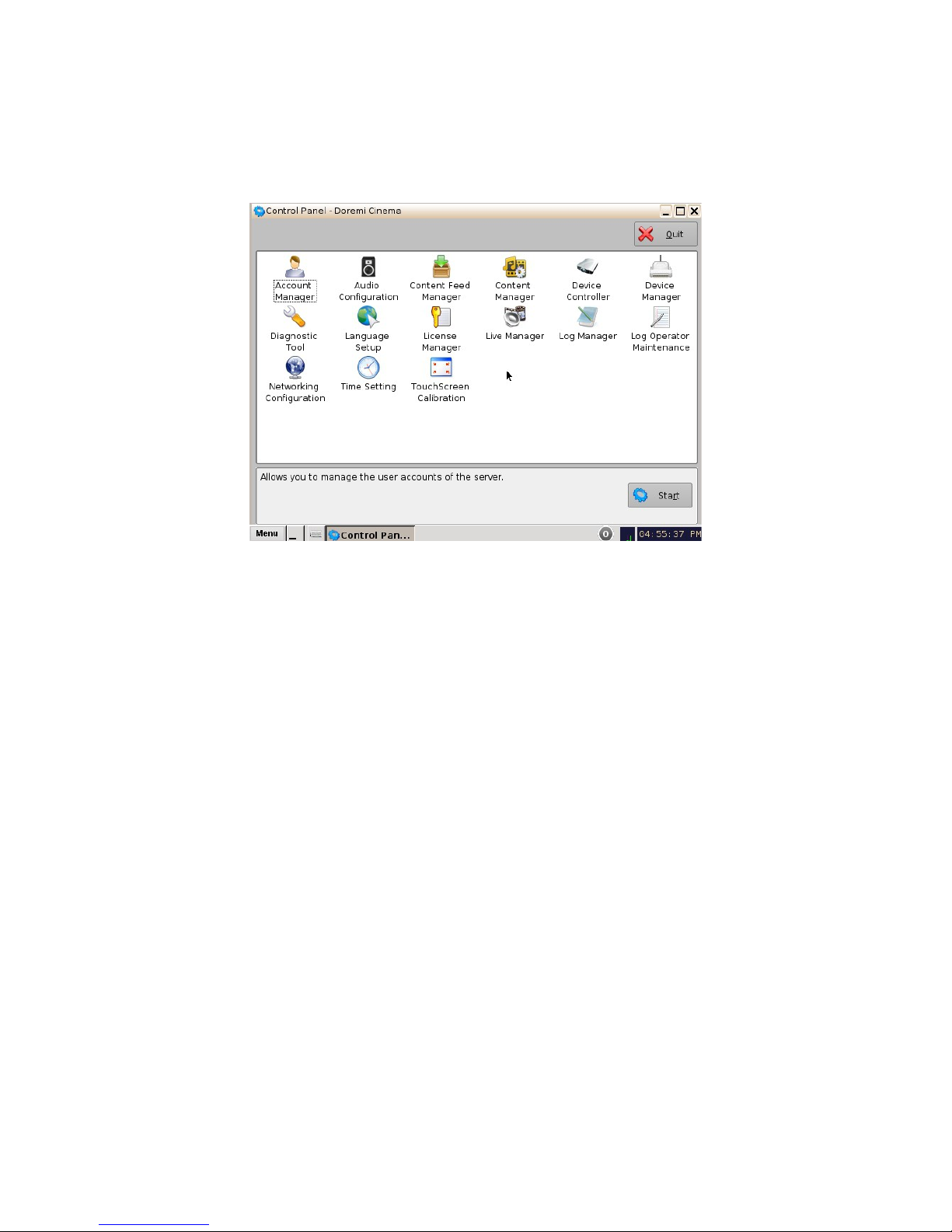
6 Control Panel
• To access the Control Panel window, go to Menu and click on Control Panel.
• The following window will appear:
Figure 13: Control Panel Window
• The Control Panel window provides access to various applications as listed below: See
Figure 13 above for more information.
1. Account Manager: Allows the user to add/remove/edit user accounts.
2. Audio Configuration: Allows the user to route all audio tracks to operator-designated
outputs (only SMPTE content).
3. Content Feed Manager: Allows the user to add an FTP ingest server.
4. Content Manager: Allows the user to browse, manage and export all the content available
on the player including: ShowPlaylists, CPLs, KDMs and Doremi Licenses.
5. Device Controller: Allows the user to create/edit/register devices in a simplified manner.
6. Device Manager: Allows the user to add different projectors, close caption devices, subtitle
devices, etc.
7. Diagnostic Tool: Provides the user with Diagnostic information about the system. See
document “Diagnostic Tool User Guide.”
8. Language Setup window: Allows the user to change the language used on the unit.
9. License Manager: Displays and manages software licenses installed on the unit.
10. Live Manager: Allows the user to create a device as source of live events.
11. Log Manager: Allows the user to automatically configure SMPTE and System logs.
12. Log Operator Maintenance: Allows the user to log important information (e.g., hard disk
replacement, projector lamp replacement, etc.). This application helps the system
administrator keep track of any change operated in a theater booth.
______________________________________________________________________________________
D2K.OM.001822.DRM Page 17 of 177 Version 1.5
Doremi Labs
Page 18
13. Network Configuration: Set up and modify network connections.
14. Time Setting: Due to DCI requirements, users can only set the time to no more than 30
minutes per calendar year on a Dolphin DCI FIPS 1.0 board. For Dolphin DCI FIPS 1.2
boards, you can only adjust the RTC (Real Time Clock) time within DCI allowed-time of 6
minutes per calendar year.
15. Touch Screen Calibration: Initiates the touch screen calibration process (only applicable to
models with a touchscreen).
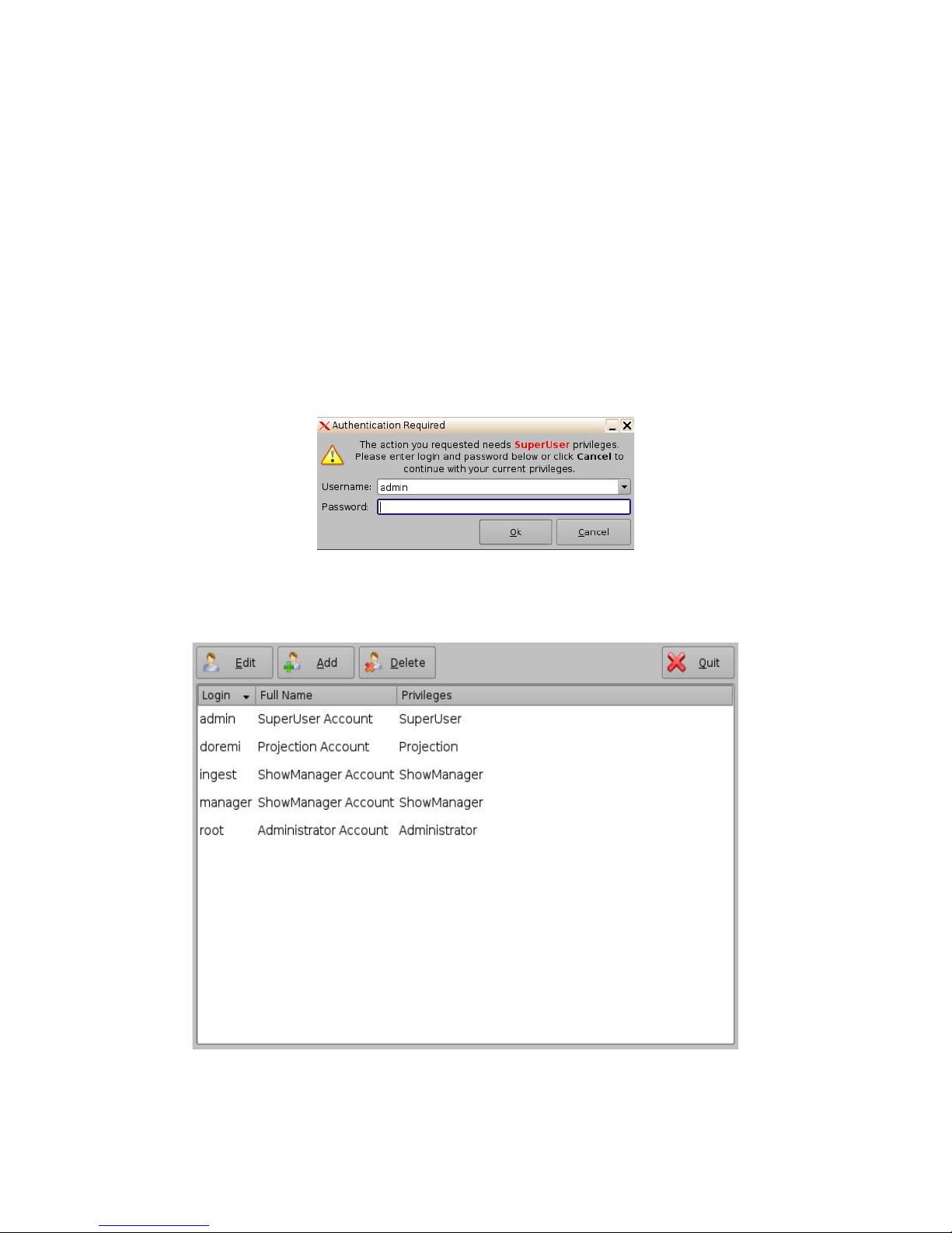
6.1 Account Manager GUI
• To access the Account Manager GUI, double-click on the Account Manager icon within the
Control Panel window or select it and click the Start” button located on the right-bottom side
of the Control Panel window.
• Input the appropriate password to continue and press the Ok button.
Figure 14: Password Confirmation Window
• The following window will appear:
______________________________________________________________________________________
D2K.OM.001822.DRM Page 18 of 177 Version 1.5
Figure 15: Account Manager GUI
Doremi Labs
Page 19
• The Account Manager GUI allows the user to edit, add, and delete user accounts (Figure
15).
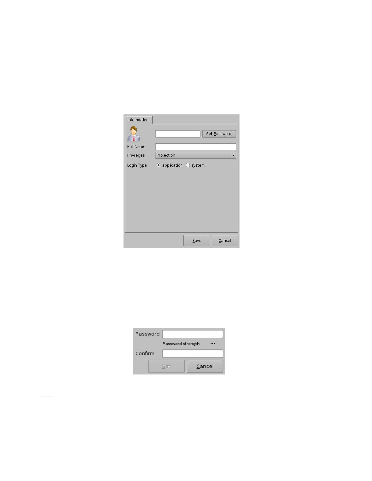
6.1.1 Add a New User Account
• To add a new user account, click the Add button (Figure 15).
• The following window will appear:
Figure 16: Account Manager GUI – New User Addition
• Enter the username (to be used for log in) in the upper empty field and the associated “Full
Name” used to describe the user. Both names will be displayed in the Control Panel
window after the new user addition is completed.
• Define the password by clicking the “Set Password” button.
• The following window will appear:
Figure 17: Password Definition Window
Note: The user will be provided information about the strength of the chosen password. Click the
“Set” button when the appropriate password is defined. Confirm the password in the “Confirm”
field. The user privileges need to be defined using the list-box.
• Click the Set button to save the new password.
______________________________________________________________________________________
D2K.OM.001822.DRM Page 19 of 177 Version 1.5
Doremi Labs
Page 20
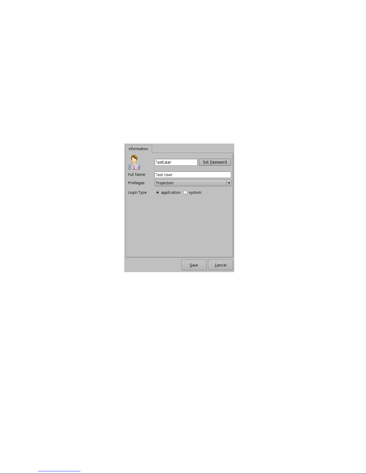
• Select the proper privileges. They are listed below from the lowest level to the highest level
of privileges:
1) Projectionist: Projectionist is a standard user allowed to use the Doremi applications
present on the unit without changing the configuration.
2) Show Manager: In addition to Projectionist's privileges, a Show Manager user is allowed to
ingest and delete content.
3) SuperUser: In addition to Show Manager's right, a SuperUser has the privileges to
configure the unit. For example, the SuperUser can update the firmware and software.
4) Administrator: An Administrator user will be a user in the group of “root.” The
Administrator can perform all of the privileges listed above in addition to creating, modifying,
and deleting user accounts.
Figure 18: Account Manager GUI – Privileges Definition
• Furthermore, two different log in types are available for the user:
1. Application: Virtual user account only works with Doremi applications.
2. System: Regular Linux user account that can be used anywhere on the system. For
example, on Linux terminal windows.
• Select the proper user account type and click the Save button.
• The new user account will be visible in the main Account Manager GUI as illustrated below:
______________________________________________________________________________________
D2K.OM.001822.DRM Page 20 of 177 Version 1.5
Doremi Labs
Page 21
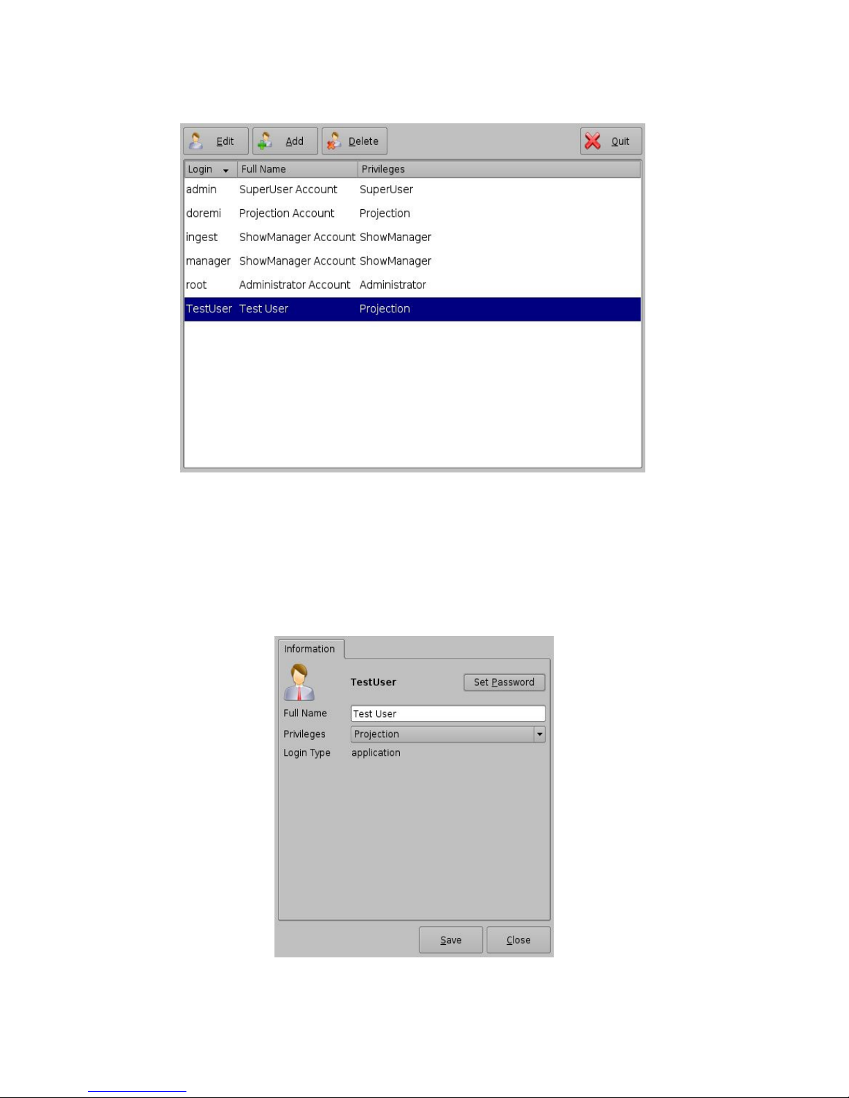
Figure 19: Account Manager GUI – New User Added
6.1.2 Edit an Existing User Account
• To edit an existing user account, select it within the Account Manager GUI and click the Edit
button.
• The following dialog box will appear allowing the user to edit the user properties but not the
username or the log in type.
Figure 20: Account Manager GUI – User Properties Editing
______________________________________________________________________________________
D2K.OM.001822.DRM Page 21 of 177 Version 1.5
Doremi Labs
Page 22
• Click the Save button when finished editing the settings (Figure 20).
• Click the Close button when finished with the configuration (Figure 20).
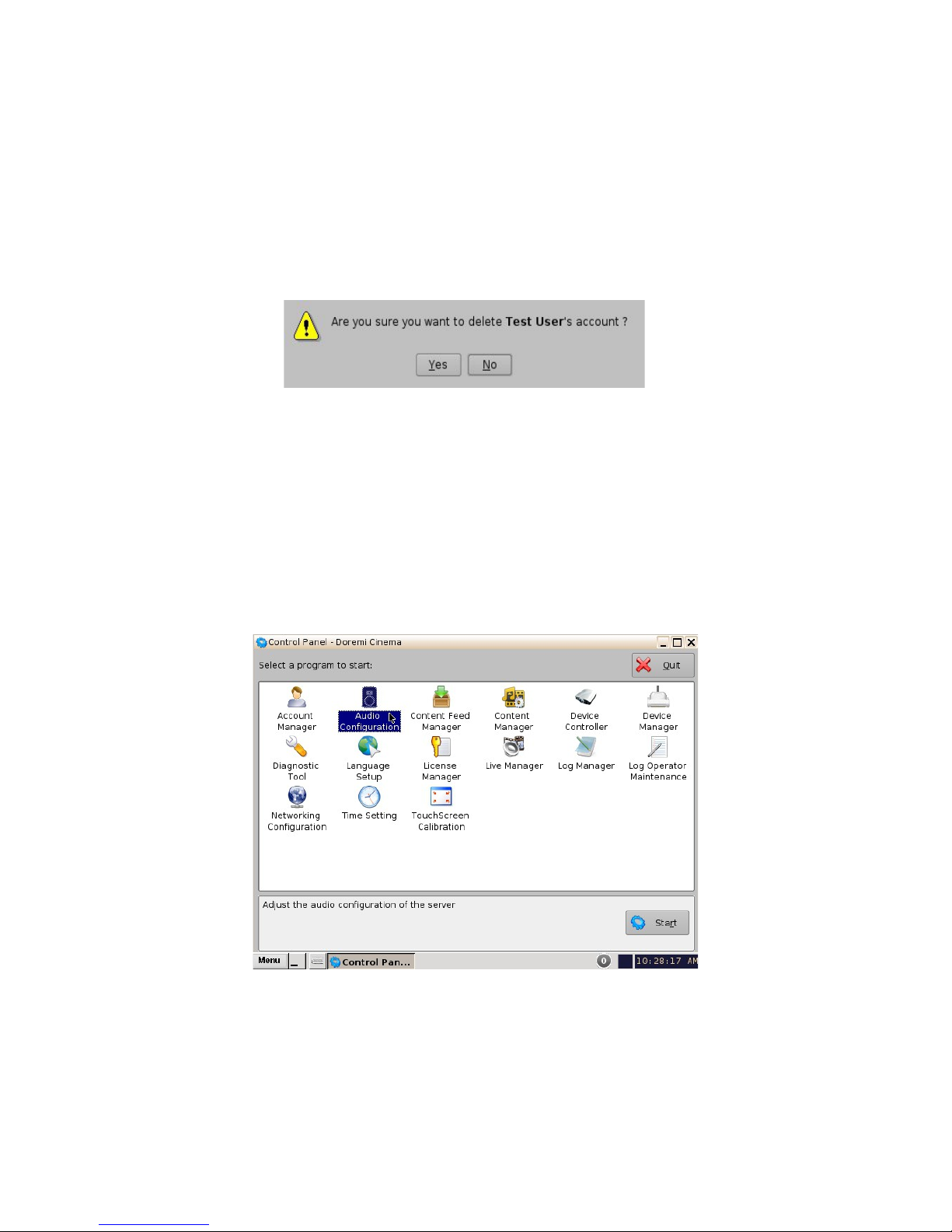
6.1.3 Delete an Existing User Account
• To delete an existing user account, select it within the main Account Manager GUI and click
the Delete button.
• The user will be asked for a confirmation. Clicking Yes will delete the user account.
Figure 21: User Account Deletion Confirmation
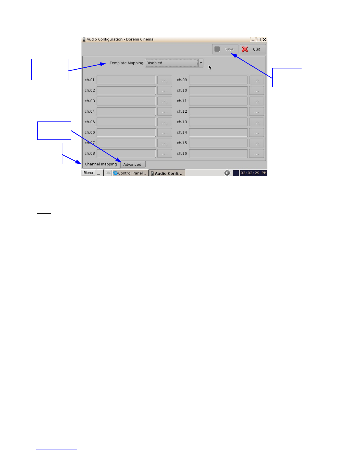
6.2 Audio Configuration
The Audio Configuration application allows the user to route all audio tracks in an SMPTE/Interop
package to operator-designated outputs. The main purpose of the mapping is to allow users to
move the HI or VI channels to a specific output. The Audio Configuration application is available in
the Control Panel.
• To open the Audio Configuration application, go to Menu -> Control Panel -> Audio
Configuration (Figure 22).
Figure 22: Control Panel with Audio Configuration Icon Selected
• An “admin” password and confirmation will be needed to perform the operation.
• The Audio Configuration window will appear.
______________________________________________________________________________________
D2K.OM.001822.DRM Page 22 of 177 Version 1.5
Doremi Labs
Page 23
Tab
Template
Mapping
Advanced
Tab
Channel
Mapping
Save
Button
Figure 23: Audio Configuration - Default Setting
• When first launched, the Audio Configuration application opens in the Channel Mapping
tab. The Template Mapping will be set to Disabled (Figure 23).
Note: All the templates, except “Disabled,” can be modified directly instead of having to select
“Custom.” Once the template is edited, the “Template Mapping” will read “Custom.”
• Available configurations include:
• Disabled: This setting is the default and as such cannot be mapped (Section
6.2.1.1).
• 4 channels: This is a pre-set configuration.
• 6 channels: This is a pre-set configuration.
• 7 channels: This is a pre-set configuration.
• 8 channels: This is a pre-set configuration.
• 9 channels: This is a pre-set configuration.
• ISDCF: This is a pre-set configuration.
• Custom: This setting allows the user to create his/her own custom audio
configuration.
______________________________________________________________________________________
D2K.OM.001822.DRM Page 23 of 177 Version 1.5
Doremi Labs
Page 24

6.2.1 Channel Mapping Tab
6.2.1.1 Disabled Configuration
Figure 24: Disabled Configuration
• Disabled: This setting is the default and as such cannot be mapped. The Disabled mapping
configuration will perform pass-through mapping, meaning channel number "X" of the CPL
audio track will be routed to audio output number "X" (variable) of the server. "X" being a
number between 1 and 16. When the configuration is grayed-out, the user cannot change
the configuration.
6.2.1.2 Pre-Defined Mapping Configurations
6.2.1.2.1 4 Channels
This configuration is defined as follows (Figure 25):
• ch.01 is Left (L): Output ch.01 will be playing the CPL's Left (L) audio channel.
• ch.02 is Right (R): Output ch.02 will be playing the CPL's Right (R) audio channel.
• ch.03 is Center (C): Output ch.03 will be playing the CPL's Center (C) audio channel.
• ch.04 is Input: ch.04 is pass-through, meaning the output channel “X” will be playing the
CPL's audio channel “X.”
• ch.05 is Surround (S): Output ch.05 will be playing the CPL's Surround (S) audio channel.
• Channels ch.06 - ch.14 are pass-through, meaning the output channel “X” will be playing
the CPL's audio channel “X.” “X” will be a value between 6 and 14.
• ch.15 is HI: Output ch.15 will be playing the CPL's Hearing Impaired (HI) audio channel.
• ch.16 is VI: Output ch.16 will be playing the CPL's Narration (VI) audio channel.
______________________________________________________________________________________
D2K.OM.001822.DRM Page 24 of 177 Version 1.5
Doremi Labs
Page 25
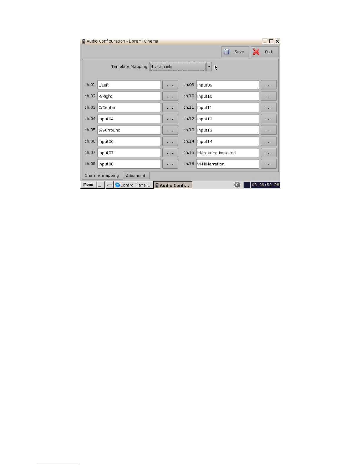
Figure 25: Audio Mapping Set to 4 Channels
______________________________________________________________________________________
D2K.OM.001822.DRM Page 25 of 177 Version 1.5
Doremi Labs
Page 26
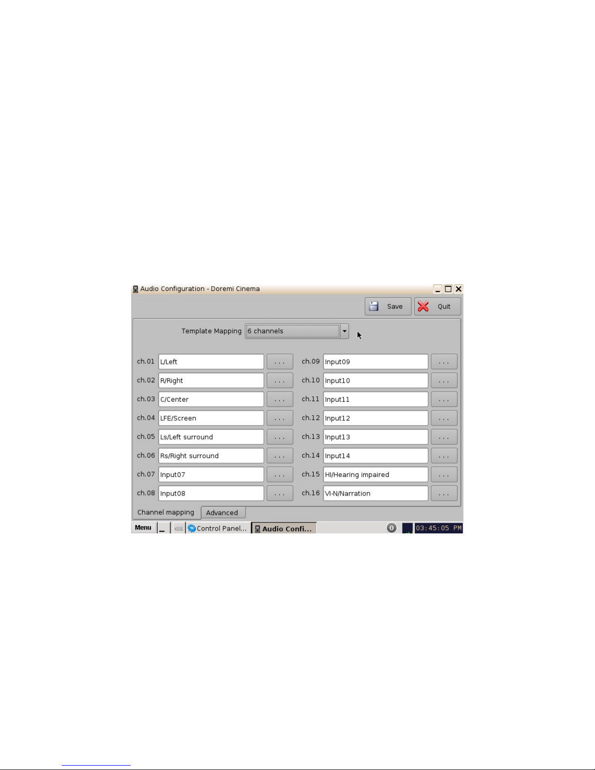
6.2.1.2.2 6 Channels
This configuration is defined as follows (Figure 26):
• ch.01 is Left (L): Output ch.01 will be playing the CPL's Left (L) audio channel.
• ch.02 is Right (R): Output ch.02 will be playing the CPL's Right (R) audio channel.
• ch.03 is Center (C): Output ch.03 will be playing the CPL's Center (C) audio channel.
• ch.04 is LFE / Screen (Sub-Woofer): Output ch.04 will be playing the CPL's LFE / Screen
(Sub-Woofer) audio channel.
• ch.05 is Left Surround (Ls): Output ch.05 will be playing the CPL's Left Surround (Ls)
audio channel.
• ch.06 is Right Surround (Rs): Output ch.06 will be playing the CPL's Right Surround (Rs)
audio channel.
• Channels ch.07 - ch.14 are pass-through, meaning the output channel “X” will be playing
the CPL's audio channel “X.” “X” will be a value between 7 and 14.
• ch.15 is HI: Output ch.15 will be playing the CPL's Hearing Impaired (HI) audio channel.
• ch.16 is VI: Output ch.16 will be playing the CPL's Narration (VI) audio channel.
Figure 26: Audio Mapping Set to 6 Channels
______________________________________________________________________________________
D2K.OM.001822.DRM Page 26 of 177 Version 1.5
Doremi Labs
Page 27
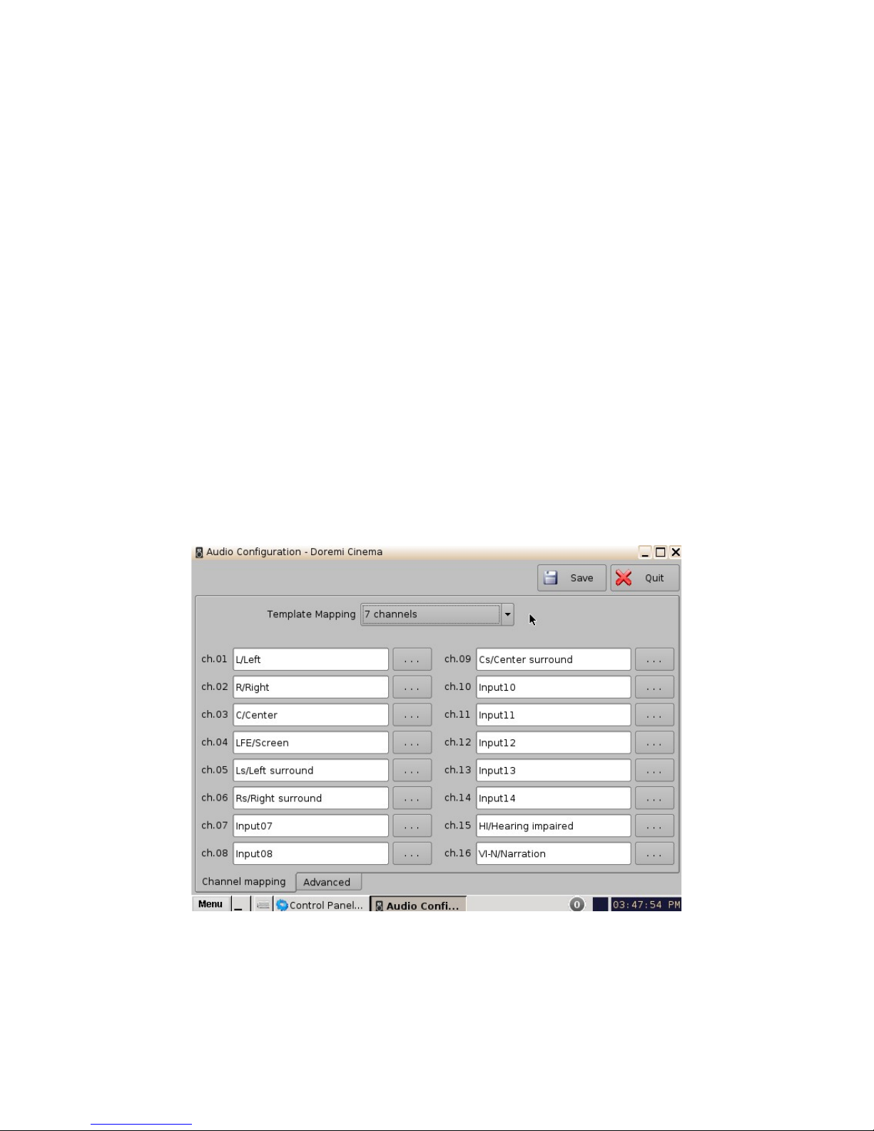
6.2.1.2.3 7 Channels
This configuration is defined as follows (Figure 27):
• ch.01 is Left (L): Output ch.01 will be playing the CPL's Left (L) audio channel.
• ch.02 is Right (R): Output ch.02 will be playing the CPL's Right (R) audio channel.
• ch.03 is Center (C): Output ch.03 will be playing the CPL's Center (C) audio channel.
• ch.04 is LFE / Screen (Sub-Woofer): Output ch.04 will be playing the CPL's LFE / Screen
(Sub-Woofer) audio channel.
• ch.05 is Left Surround (Ls): Output ch.05 will be playing the CPL's Left Surround (Ls)
audio channel.
• ch.06 is Right Surround (Rs): Output ch.06 will be playing the CPL's Right Surround (Rs)
audio channel.
• ch.07 is Input: ch.07 is pass-through, meaning the output channel “X” will be playing the
CPL's audio channel “X.”
• ch.08 is Input: ch.08 is pass-through, meaning the output channel “X” will be playing the
CPL's audio channel “X.”
• ch.09 is Center Surround (Cs): Output ch.09 will be playing the CPL's Center Surround
(Cs) audio channel.
• Channels ch.10 - ch.14 are pass-through, meaning the output channel “X” will be playing
the CPL's audio channel “X.” “X” will be a value between 10 and 14.
• ch.15 is HI: Output ch.15 will be playing the CPL's Hearing Impaired (HI) audio channel.
• ch.16 is VI: Output ch.16 will be playing the CPL's Narration (VI) audio channel.
Figure 27: Audio Mapping Set to 7 Channels
______________________________________________________________________________________
D2K.OM.001822.DRM Page 27 of 177 Version 1.5
Doremi Labs
Page 28
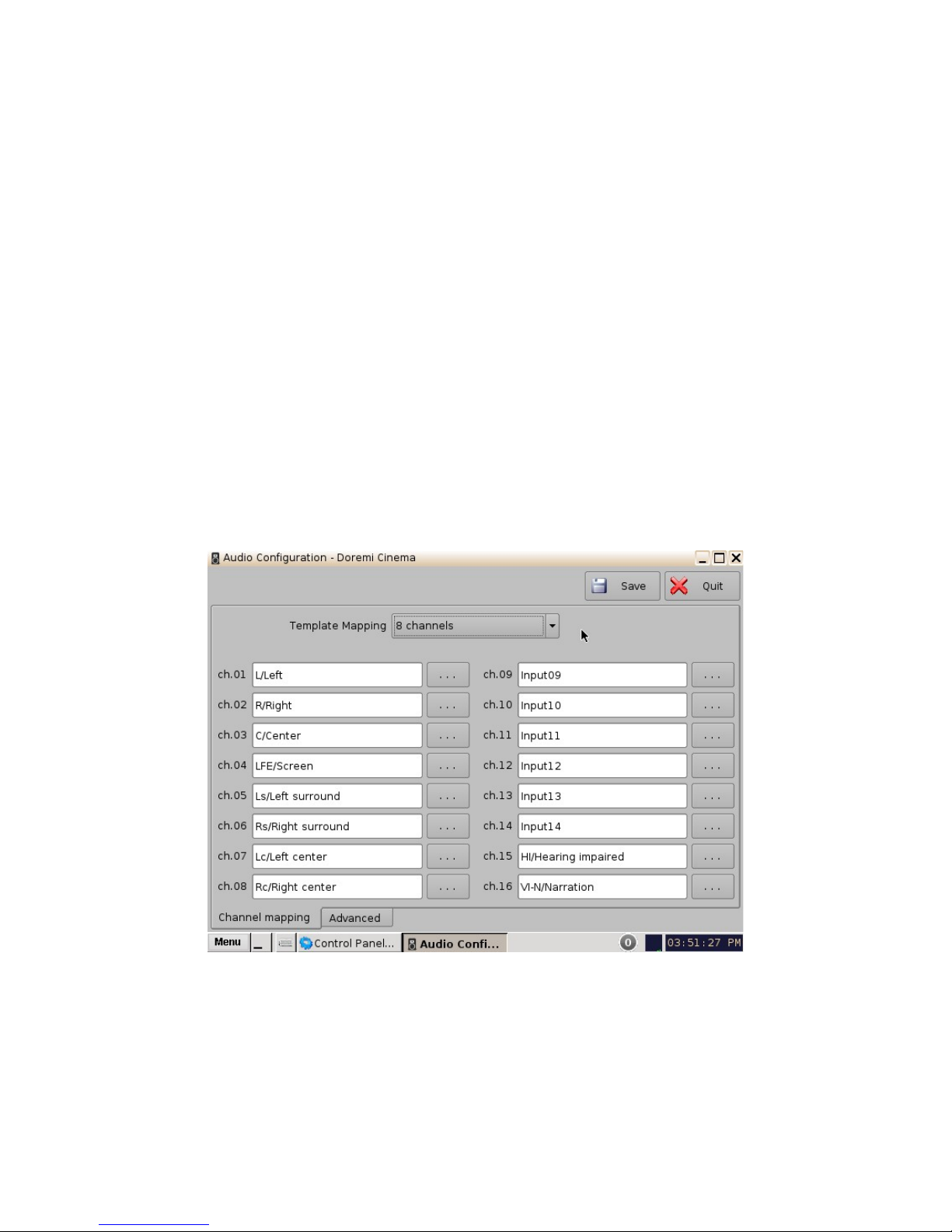
6.2.1.2.4 8 Channels
This configuration is defined as follows (Figure 28):
• ch.01 is Left (L): Output ch.01 will be playing the CPL's Left (L) audio channel.
• ch.02 is Right (R): Output ch.02 will be playing the CPL's Right (R) audio channel.
• ch.03 is Center (C): Output ch.03 will be playing the CPL's Center (C) audio channel.
• ch.04 is LFE / Screen (Sub-Woofer): Output ch.04 will be playing the CPL's LFE / Screen
(Sub-Woofer) audio channel.
• ch.05 is Left Surround (Ls): Output ch.05 will be playing the CPL's Left Surround (Ls)
audio channel.
• ch.06 is Right Surround (Rs): Output ch.06 will be playing the CPL's Right Surround (Rs)
audio channel.
• ch.07 is Left Center (Lc): Output ch.07 will be playing the CPL's Left Center (Lc) audio
channel.
• ch.08 is Right Center (Rc): Output ch.08 will be playing the CPL's Right Center (Rc) audio
channel.
• Channels ch.9 - ch.14 are pass-through, meaning the output channel “X” will be playing
the CPL's audio channel “X.” “X” will be a value between 9 and 14.
• ch.15 is HI: Output ch.15 will be playing the CPL's Hearing Impaired (HI) audio channel.
• ch.16 is VI: Output ch.16 will be playing the CPL's Narration (VI) audio channel.
Figure 28: Audio Mapping Set to 8 Channels
______________________________________________________________________________________
D2K.OM.001822.DRM Page 28 of 177 Version 1.5
Doremi Labs
Page 29
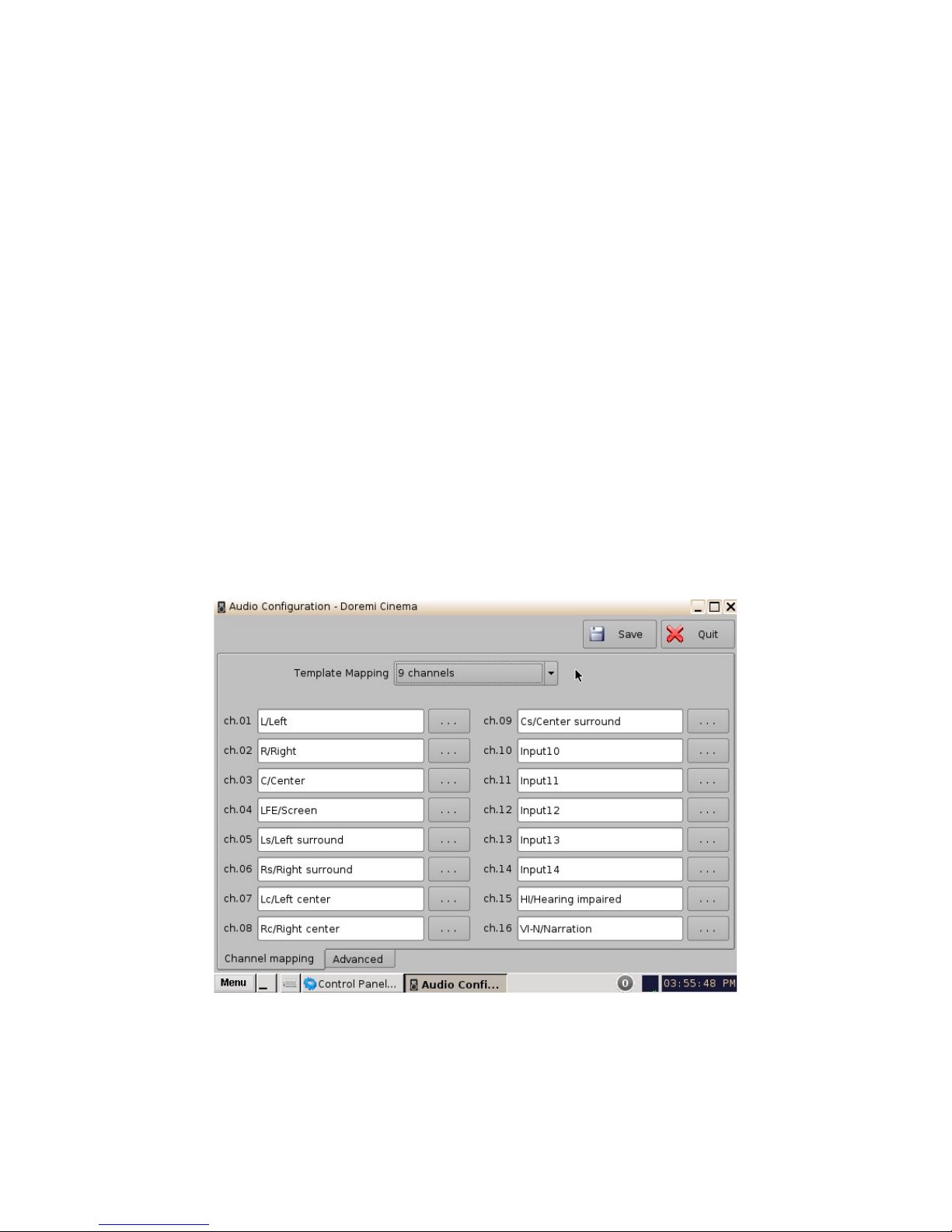
6.2.1.2.5 9 Channels
This configuration is defined as follows (Figure 29):
• ch.01 is Left (L): Output ch.01 will be playing the CPL's Left (L) audio channel.
• ch.02 is Right (R): Output ch.02 will be playing the CPL's Right (R) audio channel.
• ch.03 is Center (C): Output ch.03 will be playing the CPL's Center (C) audio channel.
• ch.04 is LFE / Screen (Sub-Woofer): Output ch.04 will be playing the CPL's LFE / Screen
(Sub-Woofer) audio channel.
• ch.05 is Left Surround (Ls): Output ch.05 will be playing the CPL's Left Surround (Ls)
audio channel.
• ch.06 is Right Surround (Rs): Output ch.06 will be playing the CPL's Right Surround (Rs)
audio channel.
• ch.07 is Left Center (Lc): Output ch.07 will be playing the CPL's Left Center (Lc) audio
channel.
• ch.08 is Right Center (Rc): Output ch.08 will be playing the CPL's Right Center (Rc) audio
channel.
• ch.09 is Center Surround (Cs): Output ch.09 will be playing the CPL's Center Surround
(Cs) audio channel.
• Channels ch.10 - ch.14 are pass-through, meaning the output channel “X” will be playing
the CPL's audio channel “X.” “X” will be a value between 10 and 14.
• ch.15 is HI: Output ch.15 will be playing the CPL's Hearing Impaired (HI) audio channel.
• ch.16 is VI: Output ch.16 will be playing the CPL's Narration (VI) audio channel.
Figure 29: Audio Mapping Set to 9 Channels
______________________________________________________________________________________
D2K.OM.001822.DRM Page 29 of 177 Version 1.5
Doremi Labs
Page 30

6.2.1.2.6 ISDCF
This configuration is defined as follows (Figure 30):
• ch.01 is Left (L): Output ch.01 will be playing the CPL's Left (L) audio channel.
• ch.02 is Right (R): Output ch.02 will be playing the CPL's Right (R) audio channel.
• ch.03 is Center (C): Output ch.03 will be playing the CPL's Center (C) audio channel.
• ch.04 is LFE / Screen (Sub-Woofer): Output ch.04 will be playing the CPL's LFE / Screen
(Sub-Woofer) audio channel.
• ch.05 is Left Surround (Ls): Output ch.05 will be playing the CPL's Left Surround (Ls)
audio channel.
• ch.06 is Right Surround (Rs): Output ch.06 will be playing the CPL's Right Surround (Rs)
audio channel.
• ch.07 is HI: Output ch.07 will be playing the CPL's Hearing Impaired (HI) audio channel.
• ch.08 is VI: Output ch.08 will be playing the CPL's Narration (VI) audio channel.
• ch.09 is Left Center (Lc): Output ch.09 will be playing the CPL's Left Center (Lc) audio
channel.
• ch.10 is Right Center (Rc): Output ch.10 will be playing the CPL's Right Center (Rc) audio
channel.
• ch.11 is Left Rear Surround (Lrs): Output ch.11 will be playing the CPL's Left Rear
Surround (Lrs) audio channel.
• ch.12 is Right Rear Surround (Rrs): Output ch.12 will be playing the CPL's Right Rear
Surround (Rrs) audio channel.
• ch.13 is Input: ch.13 is pass-through, meaning the output channel “X” will be playing the
CPL's audio channel “X.”
• ch.14 is Input: ch.14 is pass-through, meaning the output channel “X” will be playing the
CPL's audio channel “X.”
• ch.15 is Input: ch.15 is pass-through, meaning the output channel “X” will be playing the
CPL's audio channel “X.”
• ch.16 is Input: ch.16 is pass-through, meaning the output channel “X” will be playing the
CPL's audio channel “X.”
______________________________________________________________________________________
D2K.OM.001822.DRM Page 30 of 177 Version 1.5
Doremi Labs
Page 31

Figure 30: Audio Mapping Set to ISDCF
______________________________________________________________________________________
D2K.OM.001822.DRM Page 31 of 177 Version 1.5
Doremi Labs
Page 32

6.2.1.3 Custom Mapping Configuration
• Click on the drop-down menu and select Custom.
• The following window will appear.
Figure 31: Custom Mapping
• Click on the Browse button ("...") for each output channel (ch.01-ch.16) to select the CPL's
audio channel (using its label) that is to be routed.
Figure 32: Custom Mapping Parameters
______________________________________________________________________________________
D2K.OM.001822.DRM Page 32 of 177 Version 1.5
Doremi Labs
Page 33

6.2.2 Advanced Tab
This tab allows the user to add a delay between audio and video by dragging the cursor to the
desired delay. On the graphical cursor that allows values between -200 milliseconds and 200
milliseconds. All audio tracks will get the same delay. You cannot add separate delays for each
track. After the delay has been configured, click on the Save button to save the audio delay. The
selected audio delay is shown in numeric characters below the cursor field.
Figure 33: Advanced Tab
• Positive Value: The audio will be heard behind the video action.
• Negative Value: Indicates that the audio is ahead of the video action.
• The recommended value that almost matches all setups is 80 milliseconds.
______________________________________________________________________________________
D2K.OM.001822.DRM Page 33 of 177 Version 1.5
Doremi Labs
Page 34

6.2.3 SMPTE Packages
Note: The audio selection should reflect the audio package in number of audio channels.
• You can change the Template Mapping setting by clicking on the list-menu and selecting
the desired setting (Figure 24).
• Make sure to click the Save button to ensure the configuration is saved (Figure 23).
• The list of possible labels that can be routed (if present in the audio MXF file) are defined by
SMPTE as follows:
• L/Left
• R/Right
• C/Center
• LFE Screen
• Ls/Left surround
• Rs/Right surround
• Lc/Left center
• Rc/Right center
• Cs/Center surround
• Rrs/Right rear surround
• Lrs/Left rear surround
• HI/Hearing Impaired
• VI-N/Visual Impaired-Narration
6.2.4 Interop Packages
Interop audio MXF files do not contain any channel label information. Therefore, if a configuration
is selected, the routing will be executed as if the audio MXF file was created according to the
ISDCF audio mapping recommendations, which currently consists of:
Figure 34: ISDCF – Interop Recommendations
______________________________________________________________________________________
D2K.OM.001822.DRM Page 34 of 177 Version 1.5
Doremi Labs
Page 35

6.3 Content Feed Manager
The main purpose of the Content Feed Manager application is to add an FTP ingest source; in
addition, multiple units can be interconnected to share content simultaneously. The "Content Feed
Manager" makes the ingestion process quicker and simpler. This same procedure is available in
document "Content Feed Manager GUI User Manual," which is document number
D2K.OM.001597.DRM.
6.3.1 Quick Configuration
• To open the Content Feed Manager application, go to Menu -> Control Panel and double-
click on the Content Feed Manager icon (Figure 35).
Figure 35: Control Panel with Content Feed Manager Icon Selected
• You will need to authenticate yourself as "admin" by inputting the correct password to be
allowed to use this application.
Figure 36: Password Confirmation Window
• When the Content Feed Manager is started for the first time, it will be appear as illustrated
below:
______________________________________________________________________________________
D2K.OM.001822.DRM Page 35 of 177 Version 1.5
Doremi Labs
Page 36

Figure 37: Content Feed Manager GUI
6.3.2 Scan for Server
• Click the "Scan for Server" button to check and see if any servers are present on the
network. The following window will appear displaying the unit type, e-S/N, and IP as well
(Figure 38):
• Qualifications for a server include: all DCP, ShowVaults, and TMS units that have an IP
address and are connected within the same networks with the concerned unit (destination).
The units can be used as sources for material.
Figure 38: Scan for Server Button
• Scroll and select the server, then click the Add button (Figure 38). Once the server has
been selected the Content Feed Manager GUI will automatically be updated with the default
credentials.
______________________________________________________________________________________
D2K.OM.001822.DRM Page 36 of 177 Version 1.5
Doremi Labs
Page 37

Add
Button
Browse
Button
Advanced
Options
Button
Figure 39: Automatically Updated Server
• The "Identifier" field identifies the server and can be renamed for the user's convenience.
• The "Ingest Protocol" field allows the user to select the transfer protocol. Currently, only
FTP is supported.
• Once the server is selected, the IP field will automatically be populated.
• You can click on the "Test" button to determine if the unit is available in the network once it
has been selected.
• Username and Password fields are for security purposes.
• The "Remote Path" field is for the destination of the server. It is not needed when using the
"Scan for Server" method.
• Click on the Save button to save this configuration for the Content Feed Manager. The unit
is now confirmed as an ingest source for our destination unit.
______________________________________________________________________________________
D2K.OM.001822.DRM Page 37 of 177 Version 1.5
Doremi Labs
Page 38

6.3.3 Advanced Options Button
Button
Advanced
Options
Figure 40: Advanced Options Menu
• Clicking the "Advanced Options" button will open a drop-down menu where the user can
configure the following file types to be used for ingesting (Figure 40):
• Authorize "play while ingest" from this server (enabled by default)
• Key Delivery Message – allows the KDM to be ingested from the FTP or another
server registered in the netmap.
• Composition Playlist (enabled by default) – allows import or FTP of a CPL into the
server.
• Installation Package software, security manager, firmware packages for upgrades.
• Doremi License (DLM) – Doremi License Messages, e.g., Dolby3D, RealD, 4K
Enabled, etc.
• Show Playlist – click this box if you want to be able to export and then import a SPL
from one server to another.
• Click the Save button to save the configuration.
• Click the Quit button when finished.
Save
Button
______________________________________________________________________________________
D2K.OM.001822.DRM Page 38 of 177 Version 1.5
Doremi Labs
Page 39

6.3.4 Adding a Server Manually
6.3.4.1 Networking the Server(s)
• The Content Feed Manager GUI can be manually set up by clicking the Add button. This
will allow the user to add a new server for which the fields will have to be manually entered.
Figure 41: Content Feed Manager GUI
• Click the Add button to add a new server. The following window will appear:
______________________________________________________________________________________
D2K.OM.001822.DRM Page 39 of 177 Version 1.5
Doremi Labs
Page 40

Figure 42: Add New Server
• Enter the Identifier name in the Identifier field. It is recommended that a unique identifier be
used (e.g., screen 1, screen 2, etc).
• Enter the IP address for the server.
Figure 43: Add a New Server
______________________________________________________________________________________
D2K.OM.001822.DRM Page 40 of 177 Version 1.5
Doremi Labs
Page 41

• Optional: Click the "Test" button to test the IP connection. A pop-up window will appear that
will test the connection (Figure 44). Click the Close button to exist this window.
Close
Button
Figure 44: FTP Connection Test Window
• Enter the "Remote Path" for the destination of the server. Clicking the Browse button will
allow the user to locate the "Remote Path." The "Browse for Folder" window will appear.
• Select the folder which contains the content to be ingested.
6.3.5 Advanced Options
• Clicking the "Advanced Options" button will open a drop-down menu where the user can
configure the following file types to be used for ingesting.
• Authorize "play while ingest" from this server (enabled by default)
• Key Delivery Message – allows the KDM to be ingested from the FTP or another
server registered in the netmap.
• Composition Playlist (enabled by default) – allows import or FTP of a CPL into the
server.
• Installation Package software, security manager, firmware packages for upgrades.
• Doremi License (DLM) – Doremi License Messages, e.g., Dolby3D, RealD, 4K
Enabled, etc.
• Show Playlist – click this box if you want to be able to export and then import a SPL
from one server to another.
______________________________________________________________________________________
D2K.OM.001822.DRM Page 41 of 177 Version 1.5
Figure 45: Browse for Folder Window
Doremi Labs
Page 42

• Click the Save button to save the configuration.
• Click the Quit button when finished.
• The server is now added to the Content Feed Manager network.
Figure 46: Server Added - Example
6.3.6 Deleting a Server
You can delete a server from the Content Feed Manager list by selecting it and clicking on the
Delete button. This will also remove it from the Ingest Manager drop-down list of servers to ingest
from. See Figure 46 for the Delete button.
6.3.7 Ingesting from a Server that was Added
• In order to ingest material (restrictions are based on the Advanced Options settings) on our
destination unit, you will need to open the Ingest Manager application (Menu ->Doremi
Apps.-> Ingest Manager). Select the unit that was just added (as a source/feed) in the
Content Feed Manager application.
• This will populate the Ingest Manager application scan tab window with all the content
available for ingest from the selected source/feed unit.
• You can now select the desired material to ingest.
______________________________________________________________________________________
D2K.OM.001822.DRM Page 42 of 177 Version 1.5
Doremi Labs
Page 43

Figure 47: Ingest Manager with Material Ready to Ingest
______________________________________________________________________________________
D2K.OM.001822.DRM Page 43 of 177 Version 1.5
Doremi Labs
Page 44

6.4 Content Manager
The Content Manager application is a new graphical user interface (GUI), that allows the user to
browse, manage and export all the content available on the player including: ShowPlaylist, CPL,
KDM and Doremi License. The user has an application to access content information that was not
available previously. The Content Manager application is available in the Control Panel.
• To open the Content Manager application, go to Menu -> Control Panel and double-click
on the Content Manager icon (Figure 48).
Figure 48: Control Panel with Content Manager Icon Selected
• The following window will appear:
______________________________________________________________________________________
D2K.OM.001822.DRM Page 44 of 177 Version 1.5
Doremi Labs
Page 45

6.4.1 Home Page
Figure 49: Content Manager Main Tab
• A complete CPL is a CPL that is playable.
• An incomplete CPL misses elements, therefore is not playable.
• Unavailable CPL might be listed by an SPL, but it might have been deleted from the unit.
• Valid KDMs are KDMs that have not expired yet and are for trusted devices.
• Invalid KDMs are KDMs that are either expired or for the wrong trusted device.
• Expired KDMs are KDMs with a validity date that has expired.
• Not yet valid KDMs are for KDMs made in advance, not valid in present, to be used in the
future.
• Valid License is a license that has not expired.
• Expired License is a license with validity date that has expired.
• Not yet valid are licenses available on the unit, not valid in present, but valid only for future
use.
______________________________________________________________________________________
D2K.OM.001822.DRM Page 45 of 177 Version 1.5
Doremi Labs
Page 46

• The main page (Home Page) will display how much space is available on the unit.
• Click on the House icon indicated by a green arrow pointing to the "Home Page" button to
• These pages will show the user all details for the Composition Playlists, Decryption Keys,
Drop-Down
Menu
Button
access more pages.
Show Playlists, Licenses and other related fields that are on the unit (Figure 50).
Figure 50: Content Manager Home Page Tab
______________________________________________________________________________________
D2K.OM.001822.DRM Page 46 of 177 Version 1.5
Doremi Labs
Page 47

6.4.2 Composition Playlists Page
6.4.2.1 Actions Button
• Click on the House icon and select "Composition Playlists" from the drop-down menu.
• The following page will appear showing all the CPLs that are available on the unit.
Actions
Button
Info
Button
Reload
Button
Navigation
Buttons
Figure 51: Content Manager Composition Playlists Tab
• The green arrows to the right of the window allow the user to navigate up and down when
searching for a CPL (Figure 51).
Green
• The Reload button allows the user to refresh the list of CPLs (Figure 51).
• Select a CPL and click on the "Actions" button to get more options (Figure 51).
• The "Actions" button will allow you to (Figure 52):
• Delete a CPL
• Perform an Integrity Check
• Perform a Sanity check
• Export a CPL
______________________________________________________________________________________
D2K.OM.001822.DRM Page 47 of 177 Version 1.5
Doremi Labs
Page 48

Actions
Button
Figure 52: Content Manager Composition Playlists Tab
• To delete a CPL, scroll to the desired CPL, select it and then click the "Actions" button and
select Delete.
• A Manager authentication password will be required to delete the CPL.
• A "Delete Composition Playlist" confirmation window will appear: Click Delete to confirm the
deletion or press Cancel to abort the operation (Figure 53).
• Check the "Delete all KDM..." check-box if you want to delete the KDMs for the selected
CPL.
______________________________________________________________________________________
D2K.OM.001822.DRM Page 48 of 177 Version 1.5
Doremi Labs
Page 49

Figure 53: Delete Composition Playlist Window
• Integrity Check: This function will verify the hash/checksum (SHA-256) of the selected CPL.
It verifies all MXF files that were properly ingested and that no corruption occurred during
the ingest process.
• To perform an Integrity Check, select the desired CPL and select "Integrity check"
from the "Actions" drop-down menu.
• The following window will appear, which will run a test on each file of the CPL
(Figure 54).
• The results of the integrity check of each file are shown in the "Result" column.
• Results include:
• Green check-mark indicates Checksum "Ok"
• The word "Missing" in red indicates that the file is not present according to
the asset map of the CPL.
• The word "Failed" means that the file is corrupted.
• Progress check percentage operation is in progress.
______________________________________________________________________________________
D2K.OM.001822.DRM Page 49 of 177 Version 1.5
Figure 54: Integrity Check Window
Doremi Labs
Page 50

Note: The test might run for an extended period of time (e.g., 45 minutes, depending on the CPL
size). Choose this test only if doubts persist about the integrity of the CPL.
• Click the Close button when the Integrity Check is completed.
• Sanity Check: This function will check the sanity of the selected CPL.
• To perform a Sanity Check, select the desired CPL and click "Actions" button and
select "Sanity Check" item.
• The following window will appear, which will automatically run a test on each of the
following security aspects of the CPL.
• Checking signature:
• Checking KDM is valid:
• Checking asset’s existence:
• Checking timings coherency:
• Checking index files:
• Checking duration coherency:
• Checking video coherency:
• Checking audio coherency:
• Checking minimum duration:
• Checking timedtext files:
Figure 55: Sanity Check Window
• Once the test is complete, click the Close button (Figure 55).
• Export: This function will export the CPL to a desired location (e.g., a USB flash drive).
• To export a CPL, select the desired CPL, and click the "Actions" button. Select the
"Export" menu item.
• The "Export CPL" window will appear (Figure 56):
______________________________________________________________________________________
D2K.OM.001822.DRM Page 50 of 177 Version 1.5
Doremi Labs
Page 51

Figure 56: Export CPL Window
• Select the location where you want to export the CPL to (e.g., USB Disk #0) and
then click the Export button (Figure 57).
Export
Button
Figure 57: Export CPL Window
• The following window will appear showing the CPL being copied to the USB (Figure
58).
Note: The current software does not support NTFS file system to export to. If your USB is
formatted as NTFS, then an error message will appear to indicate that the file was not exported.
Currently, the supported file system formats for exporting include: FAT (limit 4GB per file), FAT 32
(limit 4GB per file), ext2, ext3, and HFS.
______________________________________________________________________________________
D2K.OM.001822.DRM Page 51 of 177 Version 1.5
Doremi Labs
Page 52

Figure 58: Copy CPL Window
• Once the CPL has been copied to the USB, the following window will appear:
Figure 59: "OK" Window
• Click the Ok button to complete the export (Figure 59).
______________________________________________________________________________________
D2K.OM.001822.DRM Page 52 of 177 Version 1.5
Doremi Labs
Page 53

6.4.2.2 Info Button
The "Info" button displays general information about the CPL. The information displayed includes:
KDM, Properties, Show Playlists that the CPL is a part of, and Assets. Any time the user wants to
exist the CPL Information window, click on the Close button located in the bottom-right.
• To use this function, select a CPL and click the "Info" button.
• The following window will appear (Figure 60):
6.4.2.2.1 Properties Tab
• The Properties tab displays the following information about the CPL (Figure 60):
• Title
• UUID (Universally Unique Identifier)
• Creation date
• Package size
• Duration
• Edit rate (frame rate)
• Kind (e.g., trailer, feature, etc.)
• Creator
• Issuer
• Sound: Channel count, Quantization bits, Encoding.
• Picture: Encoding and Dimension.
Figure 60: CPL Information Window - Properties Tab
______________________________________________________________________________________
D2K.OM.001822.DRM Page 53 of 177 Version 1.5
Doremi Labs
Page 54

6.4.2.2.2 Assets Tab
• The Assets tab displays information on all the Reels that compose the CPL and the Assets
in each Reel (Reel number, subtitle and sound). See Figure 61 below.
Figure 61: CPL Information Window - Assets Tab
______________________________________________________________________________________
D2K.OM.001822.DRM Page 54 of 177 Version 1.5
Doremi Labs
Page 55

6.4.2.2.3 SPL(s) Tab
• The SPL(s) tab displays information related to all of the Show Playlists that contain the
selected CPL.
Figure 62: CPL Information Window - SPL(s) Tab
• The SPL information window will appear. Each SPL in this list contains the CPL that
information is sought for (Figure 63):
• Select the desired SPL from the "Name" column and click the Open button. This will open
the SPL information window Properties tab that will show all the names of the CPLs inside
that SPL.
• The second tab of the SPL information window displays the related schedules
(Figure 64).
______________________________________________________________________________________
D2K.OM.001822.DRM Page 55 of 177 Version 1.5
Doremi Labs
Page 56

Figure 63: SPL Information Window - Properties Tab
Figure 64: SPL Information Window - Related Schedules Tab
______________________________________________________________________________________
D2K.OM.001822.DRM Page 56 of 177 Version 1.5
Doremi Labs
Page 57

• In this window you can select any CPL that is part of the SPL by clicking the Open button.
The user will be transferred to the selected CPL Information window (Figure 65).
Figure 65: CPL Information Window - Properties Tab
______________________________________________________________________________________
D2K.OM.001822.DRM Page 57 of 177 Version 1.5
Doremi Labs
Page 58

6.4.2.2.4 KDM(s) Tab
This tab will display the UUID and Validity of each KDM for the concerned CPL (Figure 66). If you
select a KDM and select Open it will take you to the "KDM Information" window Properties tab
(Figure 67).
Figure 66: CPL Information Window - KDM(s) Tab
• The Properties tab displays the following information about the selected KDM
(Figure 67):
• Message ID: KDM UUID
• Message Type: MessageType field of the KDM
• Annotation Text: AnnotationText field of the KDM
• Ingestion Date: Date on which the KDM was ingested into the server
______________________________________________________________________________________
D2K.OM.001822.DRM Page 58 of 177 Version 1.5
Doremi Labs
Page 59

Figure 67: KDM Information Pop-Up Window
• The Content tab contains the following information about the related CPL (Figure 68):
• CPL Title:
• CPL ID (CPL UUID):
• Audio Forensic Info (enabled / disabled):
• Video Forensic Info (enabled / disabled):
Figure 68: KDM Information Pop-Up Window
______________________________________________________________________________________
D2K.OM.001822.DRM Page 59 of 177 Version 1.5
Doremi Labs
Page 60

• The Validation tab contains precise information about the date and time of the validity of the
KDM, an approximation of the period for which the KDM is valid as well as Signer
information (subject and issuer). See Figure 69 below.
Figure 69: KDM Information Pop-Up Window
• The TDL tab contains the list about the trusted devices (projectors) and their certificate
thumbprints (Figure 70).
Figure 70: KDM Information Pop-Up Window
______________________________________________________________________________________
D2K.OM.001822.DRM Page 60 of 177 Version 1.5
Doremi Labs
Page 61

6.4.3 Search Tool
The Content Manager allows the user to search for CPLs, in the Composition Playlist tab, using the
search field located on the top portion of the window (Figure 71). The Search Tool allows you to
sort the CPLs based on the following categories (elements), or performing a Custom Search, which
is not case-sensitive, by entering a search pattern:
• All Elements, Incomplete Elements, Feature, Rating, Teaser, Test, Trailer, Transitional, or
Custom Search.
Search
Tool
Black-
highlighted
area
Figure 71: Search Tool
• For example, select "Trailer" to sort the CPLs. The CPLs will be alphabetically ordered
within the Trailer category (Figure 72).
Note: The black-highlighted area (Figure 71) indicates whether the content is 3D or has subtitles
(ST).
______________________________________________________________________________________
D2K.OM.001822.DRM Page 61 of 177 Version 1.5
Doremi Labs
Page 62

Figure 72: Search Field
6.4.4 Decryption Keys Page
The Decryption Keys page displays the list of all encrypted CPLs on the unit and the corresponding
KDMs with a description of the following information (Figure 73):
• Expiration date
• Electronic Serial Number of the unit
• UUID of the KDM
• The user can perform a Sanity Check of the KDM as well as delete the selected KDM.
• Click on the Home Page tab and scroll down and select Decryption Keys.
• The following window will appear:
______________________________________________________________________________________
D2K.OM.001822.DRM Page 62 of 177 Version 1.5
Doremi Labs
Page 63

Figure 73: Decryption Keys Tab
______________________________________________________________________________________
D2K.OM.001822.DRM Page 63 of 177 Version 1.5
Doremi Labs
Page 64

6.4.5 Performing a KDM Sanity Check
• Select a KDM from the KDM list and click the "Actions" button and select the Sanity Check
menu item.
• The Sanity Check window will appear displaying the results of the Sanity Check
(Figure 74).
• The results of the Sanity Check are displayed in the bottom-left corner of the Sanity Check
window (Figure 74).
Figure 74: Decryption Keys Tab
• Once the Sanity Check is completed, click the Close button (Figure 74).
• To view the properties of any KDM, select it from the list and the information will be
displayed in the bottom half of the window (Figure 75).
______________________________________________________________________________________
D2K.OM.001822.DRM Page 64 of 177 Version 1.5
Doremi Labs
Page 65

KDM
Information
KDM
Properties
Field
Figure 75: Decryption Keys Page: KDM Selected - Properties Shown
• This same information can be obtained by selecting the KDM line and clicking the
Information button.
______________________________________________________________________________________
D2K.OM.001822.DRM Page 65 of 177 Version 1.5
Doremi Labs
Page 66

6.4.6 Show Playlists Page
This page displays all the SPLs available on the unit together with the following information:
• SPL Duration
• SPL UUID
Actions
Button
SPL
Information
Button
Figure 76: Show Playlists Page
• The following Actions can be performed from the Show Playlists page: Delete and Export
SPLs.
6.4.6.1 Delete an SPL
• Select an SPL from the list and click the "Actions" button (Figure 76) and select Delete from
the drop-down menu.
• A manager password and confirmation will be needed to perform the operation.
• Confirm or deny the deletion with the pop-up confirmation window by pressing Yes or No.
6.4.6.2 Export an SPL
• Insert a USB device in a USB port on the unit.
• Select an SPL from the list and click the "Actions" button (Figure 76) and select Export from
the drop-down menu.
• Select the USB device to export the SPL to.
• Click on the Export button.
• When the Export is finished, click on the Ok button and remove the USB device.
______________________________________________________________________________________
D2K.OM.001822.DRM Page 66 of 177 Version 1.5
Doremi Labs
Page 67

Note: The current software does not support NTFS file system to export to. If your USB is
formatted as NTFS, then an error message will appear to indicate that the file was not exported.
Currently, the supported file system formats for exporting include: FAT (limit 4GB per file), FAT 32
(limit 4GB per file), ext2, ext3, and HFS.
6.4.7 Information Button
• Select an SPL and click the Information button to get details regarding the SPL.
• The SPL Information window pops up and displays SPL Properties tab (all CPLs in it) and
the Related Schedules tab (see Figure 63 & Figure 64).
6.4.8 Licenses Page
• To get to the Licenses page you must click on the Home icon and select the Licenses menu
item. The Licenses page will appear (Figure 77).
• The Licenses page contains the list of all the licenses available on the unit including the
expiration date and short description of the usage of the license. On this page, the user is
allowed to delete licenses.
______________________________________________________________________________________
D2K.OM.001822.DRM Page 67 of 177 Version 1.5
Figure 77: Licenses Page
Doremi Labs
Page 68

6.4.9 Delete a License
• Select the license from the list and then click on the "Actions" button (Figure 78).
• Click on Delete.
Actions
Button
Figure 78: Licenses Page
• A Manager password will be needed to perform the deletion (Figure 79).
Figure 79: Password Confirmation Window
• Click on Yes to confirm the deletion (Figure 80).
Figure 80: Confirmation Window
______________________________________________________________________________________
D2K.OM.001822.DRM Page 68 of 177 Version 1.5
Doremi Labs
Page 69

6.5 Device Controller
The Device Controller application is meant for IMB/Sony related configurations. Currently, the
DCP-2000 and DCP-2K4 cannot be controlled through this application.
6.6 Device Manager
The Device Manager is an application used to configure the connection between a unit and cinema
projector(s). It also provides for the use of Ethernet commands for the control of theater automation
devices.
• To run the Device Manager, go to Menu → Doremi Apps. → Device Manager.
• The following window will appear:
Add
button
Figure 81: Device Manager Graphical User Interface (GUI)
6.6.1 Adding a Projector
• To connect a projector to the unit (server), click the Add button (Figure 81).
• The "Add Device" window will appear:
• Select the item called “Projector” and click the Add button as illustrated below:
______________________________________________________________________________________
D2K.OM.001822.DRM Page 69 of 177 Version 1.5
Doremi Labs
Page 70

“Projector” item
selected
Add
Button
Figure 82: Device Selection Window – “Projector” Item Selected
• The main configuration window will be updated to reflect the addition of the "Projector"
device. The user will be able to enter the projector parameters as illustrated below:
Delete
Button
Projector
Identifier
Head IP
Field
Vendor IP
Field
Figure 83: Device Manager GUI – Projector Fields Configuration
• To perform the projector configuration, follow the steps below:
• Specify a projector identifier (e.g., projector name, screen #) in the first field.
"Enable
subtitles"
Test
Button
Projector
Model
Username and
Password (do
not change)
Note: The selection of primary and secondary projectors only applies to Sony SRX Projectors. For
all other projector types, please select "Primary." Also, this could apply if the user were to use dual
projector for 3D (left projector would be “Primary” and right projector would be “Secondary”).
______________________________________________________________________________________
D2K.OM.001822.DRM Page 70 of 177 Version 1.5
Doremi Labs
Page 71

• Choose the correct projector model to connect to the unit using the “Projector model”
field(s).
• Select the model series for the projector from the drop-down menu on the right. The
projector model series varies for all projector manufacturers.
• Enter the Head IP address and then click the “test” button.
• If the "DLP Head Connection Test" fails, the IP address is invalid.
• Choose to either enable or disable the subtitles.
Note: If the user enables subtitles without the unit being connected to a projector, then the server
will not operate properly.
• Input the appropriate username and password. The username and password will vary for all
projector manufacturers.
• Check the Enabled check box at the top right corner of the GUI.
• Click the Save button to record the settings. A password confirmation page will appear.
Enter the password to save and record the settings.
6.6.2 Removing a Device or Projector
• To remove a device or projector, click on it in the left part of the Device Manager GUI.
• Click the Delete button (Figure 83).
______________________________________________________________________________________
D2K.OM.001822.DRM Page 71 of 177 Version 1.5
Doremi Labs
Page 72

6.6.3 Automation Libraries Management
Support for theater automation control is also provided. The list of currently supported devices is
the following:
• eCNA
• JNior
A pre-built library of supported automation commands are available for each of these two devices.
These automation commands can then be added to Macro Cues.
6.6.4 Adding an eCNA Device
• To add the eCNA device, click the Add button in the Device Manager window
(Figure 84).
• The "Add Device" window will appear. Select the item called “eCNA” and click the Add
button.
• The Device Manager GUI will be updated to reflect the addition of the eCNA device.
• Input the name of the eCNA device in the Identifier field.
• Input the eCNA Server IP address in the appropriate field as illustrated below:
Add
Button
Delete
Button
eCNA IP
Address Field
Enabled
Checked
Figure 84: Device Manager GUI – eCNA Device Configuration
• If not already done so, check the Enabled check-box in the top-right corner of the GUI.
• Click the Save button to record the settings. A window asking for the password will appear.
Enter the password to save the settings and proceed.
• Click Quit when finished with the configuration. If not, continue and add more devices.
______________________________________________________________________________________
D2K.OM.001822.DRM Page 72 of 177 Version 1.5
Doremi Labs
Page 73

6.6.4.1 Removing an eCNA Device
• To remove the eCNA device, select it in the Device Manager GUI and click the Delete
button (Figure 84).
6.6.5 Adding a JNior Device
• To add the JNior device, click the Add button in the Device Manager window.
• The "Add Device" window will appear. Select the item called “JNior” and click the Add
button.
• The Device Manager GUI will be updated to reflect the addition of the JNior device (Figure
85).
• Input the name of the JNior device in the Identifier field.
• Input the JNior Server IP address in the appropriate field as illustrated below
(Figure 85).
Add
Button
Delete
Button
JNior IP
Address Field
Figure 85: Device Manager GUI – JNior Device Configuration
• The port number field will already contain the appropriate value (factory default value).
Note: The JNior device documentation will provide the correct username and password (factory
default values).
• Click the Save button to record the settings. A window will appear asking for a password.
Enter the password to proceed.
• Click Quit when finished with the configuration. If not, continue and add more devices.
______________________________________________________________________________________
D2K.OM.001822.DRM Page 73 of 177 Version 1.5
Doremi Labs
Page 74

6.6.5.1 Removing a JNior Device
• To remove the JNior device, click on it in the Device Manager GUI.
• Click the Delete button (Figure 85).
6.6.6 Adding a Raw Device
A “Raw” device allows for communication with an external device across an Ethernet connection
using "Raw" data formatted as text or binary strings.
• To add a Raw device, click the Add button.
• The "Add Device" window will appear. Select the item called “Raw” and click the Add
button.
• The Device Manager GUI will be updated to reflect the addition of the Raw device (Figure
86).
• Input the name of the Raw device in the Identifier field.
Quit
Button
Save
Button
Figure 86: Device Manager GUI – Raw Device Configuration
• Specify a vendor name in the Vendor field.
• Specify a product name in the Product Name field.
• Enter the IP address of the Raw device in the Device IP field (Figure 86).
• Choose the protocol to be used (TCP or UDP) and the proper Port number.
• Click the Save button to record the settings (Figure 86). A window will appear asking for a
password. Enter the password to proceed.
• If finished with the configuration, click the Quit button.
______________________________________________________________________________________
D2K.OM.001822.DRM Page 74 of 177 Version 1.5
Doremi Labs
Page 75

6.6.7 Removing a Raw Device
• To remove the Raw device, click on it in the Device Manager GUI and press the Delete
button (Figure 86).
6.6.8 Adding a Serial Device
The Serial device is used to be able to manage incoming and outgoing messages over a serial
port. It is a new feature that allows the user to control or interact with some old legacy device that
usually communicates only through serial cables. Outgoing messages can be sent to the
automation using a simple basic automation cue.
Incoming messages are parsed, and then sent to the playback engine in the form of a signal
trigger.
• The schema below explains how the daemon is run:
Figure 87: Serial Device Schema
• The file device.xml contains all elements to configure properly the serial port and how to
scan incoming messages. This file is conveniently managed by the Device Manager GUI
application. The generic serial device driver can manage different serial ports
simultaneously.
• Go to Menu → Doremi Apps. → Device Manager and follow the steps below. The following
window will appear:
______________________________________________________________________________________
D2K.OM.001822.DRM Page 75 of 177 Version 1.5
Doremi Labs
Page 76

Figure 88: Device Manager GUI
• Click on the Add button and select the item Serial from the pop-up list.
Figure 89: Add Device Window
• Click the Add button (Figure 89). The following window will appear:
• It is necessary to provide some configuration parameters in the window:
• Identifier is the friendly name of the new configured device.
______________________________________________________________________________________
D2K.OM.001822.DRM Page 76 of 177 Version 1.5
Doremi Labs
Page 77

• Serial Port is the internal device system filename the device driver will communicate
to.
• Usual values are:
/dev/ttyS0 for embedded serial port on the motherboard
/dev/ttyUSB0 for any USB-serial converter.
• Speed, Data, Stop Bits, Parity and Flow control are usual parameters used to
configure serial communication. Refer to the original automation documentation to
find out what the correct values are. Usual value is 115200 8N1. No flow control.
Figure 90: Device Manager GUI - Serial Device Added
• Message type: This parameter indicates how incoming text will be parsed to build
messages. In order to match most existing protocol, two different incoming message types
are handled.
• Fixed length messages: All messages are always expected to be the same length. The
user has to provide the message length parameter.
• End of message character: All messages are expected to have a special "magic"
character to indicate the end of message. This type matches most text-based protocol
with an end of line character (\n) to validate the entry. You have to provide the end of
message "magic" character. Multiple character sequence is not supported (e.g., \r\n).
Note that the "magic" character will NOT be part of the message sent to the playback
engine.
• Save the new configuration.
______________________________________________________________________________________
D2K.OM.001822.DRM Page 77 of 177 Version 1.5
Doremi Labs
Page 78

Figure 91: "fixed-length" and "end of message" Examples
Note: It may take up to 30 seconds before the new configuration is applicable.
• After the serial device has been configured, the user can set the trigger from the serial port
or automation actions to serial port.
6.6.9 ISE1 Device
The ISE1 Device provides for communication with the IMAX Secure Enclosure. If more information
is needed, please contact Doremi Labs Technical Support (Section 1.3).
6.6.10 CSS Device
The CSS Device provides for communication with the Sony Cavity Security System. If more
information is needed, please contact Doremi Labs Technical Support (Section 1.3).
6.6.11 3D Configuration
When using a DCP-2000 or DCP-2K4 configuration for 3D presentation, the projector needs to be
set to the proper color space. Contact the projector vendor to configure the projector properly.
6.6.11.1 Dolby 3D Support
To enable the Dolby 3D support, please contact Doremi Labs Technical Support to receive the
appropriate license (Section 1.3).
6.6.11.2 RealD 3D Support
To enable the RealD 3D support, please contact RealD at cinema-support@reald.com to receive
the appropriate license. Once the license has been received, follow the steps below:
• Open the Device Manager GUI by clicking on Menu → Doremi Apps. → Device Manager.
• The following window will appear:
______________________________________________________________________________________
D2K.OM.001822.DRM Page 78 of 177 Version 1.5
Doremi Labs
Page 79

Add
Button
Figure 92: Device Manager GUI
• Click the Add button.
• The list of available devices will appear as presented below:
Add
Button
• Select the “RealD 3D EQ” device and click the Add button (Figure 93).
• The device will be visible on the main Device Manager GUI as illustrated below:
______________________________________________________________________________________
D2K.OM.001822.DRM Page 79 of 177 Version 1.5
Figure 93: List of Available Devices
Doremi Labs
Page 80

Save
Button
Figure 94: RealD 3D EQ Device Added
• To complete the configuration, click the Save button (Figure 94). Enter the appropriate
password and click Ok.
6.6.11.3 Sensio 3D Support
To enable the Sensio 3D support, please contact Doremi Labs Technical Support to receive the
appropriate license (Section 1.3).
6.6.12 Closed Caption Support
To enable the Rear Window devices Closed Caption support, install the appropriate license. For
information about the Closed Caption Support, contact Doremi Labs Technical Support (Section
1.3).
6.6.13 Subtitle Engine Configuration
This sections provides instructions on how to set up the Device Manager for Subtitle Engine
support. It will allow the user to burn subtitles into the picture before being exported to the
projector. Once the license has been received, follow the steps below:
• Open the Device Manager GUI by going to Menu → Doremi Apps. → Device Manager.
• The following window will appear:
______________________________________________________________________________________
D2K.OM.001822.DRM Page 80 of 177 Version 1.5
Doremi Labs
Page 81

Add
Button
Figure 95: Device Manager GUI
• Click the Add button (Figure 95).
• The "Add Device" window will appear:
Note: In case the user already has a projector configured through Device Manager to display
subtitles, meaning that the “Enable subtitle” filed was set to Yes, adding the Subtitle Engine device
will cause a warning window to appear asking the user to disable all projector subtitle display. The
Subtitle Engine will burn the subtitle inside the picture before exporting the resulting pictures to the
projector. If the user plans to use the Subtitle Engine, click the Yes button in the warning window to
disable all projector subtitles (Figure 96).
Figure 96: Subtitle Engine Warning Window
• Select the Subtitle Engine device and click the Add button.
• The device will be visible on the main Device Manager GUI as illustrated below:
______________________________________________________________________________________
D2K.OM.001822.DRM Page 81 of 177 Version 1.5
Doremi Labs
Page 82

Figure 97: Subtitle Engine Added
• To complete the configuration, click the Save button (Figure 97).The user will be asked for
a password. Enter the appropriate password and press Ok.
6.7 Diagnostic Tool
To use the Diagnostic Tool application, please see document number "DTL.OM.000169.DRM,"
which is titled "Diagnostic Tool User Manual." Contact Doremi Labs Technical Support to receive
this document (Section 1.3).
______________________________________________________________________________________
D2K.OM.001822.DRM Page 82 of 177 Version 1.5
Doremi Labs
Page 83

6.8 Language Setup
Note: All applications are available for multi-language support except:
• Diagnostic Tool
• License Manager
• Live Manager
• Log Manager
• Log Operator Maintenance
• Networking Configuration
• Touchscreen Calibration
Note: Make sure that no application is open before setting the language.
• To change the language used on the unit, double-click the Language Setup icon in the
Control Panel window.
• The user will be asked for a password.
• The following Language Setup window will appear:
Figure 98: Language Setup Window - English
• Use the list-box to choose desired language, for example, “Espanol” (Figure 99).
Figure 99: Language Setup Window - Espanol
• The available languages include:
• German (supported)
• English (supported)
• Spanish (supported)
• French (supported)
• Norwegian (supported)
______________________________________________________________________________________
D2K.OM.001822.DRM Page 83 of 177 Version 1.5
Doremi Labs
Page 84

• Polish (supported)
• Portuguese (supported)
• Russian (Font file package required)
• Arabic (Font file package required)
• Chinese (Font file package required)
• Japanese (Font file package required)
• Taiwanese (Font file package required)
• cs-CZ – Czech (Font file package required)
• Click the OK button when finished selecting the language.
• The unit language will be updated as illustrated in the CineLister GUI shown below:
Figure 100: CineLister GUI – Spanish Language Used
______________________________________________________________________________________
D2K.OM.001822.DRM Page 84 of 177 Version 1.5
Doremi Labs
Page 85

Boxes
Figure 101: Language Setup Drop-Down List
Note: These boxes (Figure 101) indicate that the font file package is needed. Contact your local
Doremi Technical Support to obtain the appropriate font file package.
______________________________________________________________________________________
D2K.OM.001822.DRM Page 85 of 177 Version 1.5
Doremi Labs
Page 86

6.9 License Manager
• To access the License Manager GUI, double-click the License Manager icon available in
the Control Panel.
• The following window will appear (if no licenses are installed on the unit):
Figure 102: License Manager GUI
6.9.1 Adding a License
• To add a license have the license file on a USB flash drive and plug it into a USB port on
the unit.
• The Ingest Manager GUI will appear as illustrated below:
______________________________________________________________________________________
D2K.OM.001822.DRM Page 86 of 177 Version 1.5
Doremi Labs
Page 87

Ingest
Button
Select the
license to
add
Figure 103: License Ingest Example
• Select the license file(s) to install and click the Ingest button.
• The user will be asked for a password. Enter the appropriate password and press Ok.
• You do not have to reboot the unit (See Note below).
• Go back to the License Manager GUI from Menu → Control Panel. The ingested license(s)
will be visible as illustrated below:
Figure 104: License Manager GUI – Three Licenses Added
______________________________________________________________________________________
D2K.OM.001822.DRM Page 87 of 177 Version 1.5
Doremi Labs
Page 88

• To view the details of an available license, select it and click the View button.
Figure 105: License View Window
______________________________________________________________________________________
D2K.OM.001822.DRM Page 88 of 177 Version 1.5
Doremi Labs
Page 89

• The License Information window will appear providing the validity window of the license.
• To delete a license from the unit, select it within the License Manager GUI and click the
Delete button.
• After ingesting a license, the associated device (e.g., “Subtitle Engine,” “Dolby DFC 100”)
will be visible in the Device Manager GUI.
6.10 Live Manager
The Live Manger application allows the user to add a "Virtual Device" as a source of a live event.
These "Live CPLs" can be added to Show Playlists in Cinelister.
• To access the Live Manager GUI, double-click the Live Manager icon within the Control
Panel GUI.
• The user will be asked for a password. Enter the appropriate password to continue (Figure
106).
Figure 106: Password Confirmation Window
• The following window will appear:
Figure 107: Live Manager GUI
______________________________________________________________________________________
D2K.OM.001822.DRM Page 89 of 177 Version 1.5
Doremi Labs
Page 90

6.10.1 Creating a Live Event
• To create a "Live CPL" allowing a live event, click the Add button.
• The following wizard window will appear (Figure 108):
Figure 108: Live Manager – Live CPL Creation Wizard Step 1
• Select the "live source device type."
• Click the Next button. The next wizard window will appear.
• Enter the IP address of the external "Live Event" box in the Device IP field (Figure 109).
• Enter the "Live CPL" content title in the Content Title field (Figure 109).
Figure 109: Live Manager – Live CPL Creation Wizard, Step 2
• Click the Next button.
• Click the Finish button to complete the "Live CPL" creation (Figure 110).
______________________________________________________________________________________
D2K.OM.001822.DRM Page 90 of 177 Version 1.5
Doremi Labs
Page 91

Figure 110: Live Manager – Live CPL Creation Wizard, Step 3
• Clicking the Finish button will make the "Live CPL" visible in the Live Manager main window
(Figure 111).
CPL
Figure 111: Live Manager – CPL Created
Note: The MPEG Streamer format is dynamically handled. This means that the 4:2:2 vs 4:2:0
parameter is automatically detected from the MPEG stream itself. There is no need to
provide this information to the playback engine.
______________________________________________________________________________________
D2K.OM.001822.DRM Page 91 of 177 Version 1.5
Doremi Labs
Page 92

• Repeat the steps above as many times as necessary to generate another "Live CPL."
• To use the "Live CPL" allowing a live event, open CineLister (go to Menu → Doremi Apps.
→ CineLister).
• The newly created "Live CPL" will be visible under “live” in the left part of the Editor tab
allowing the user to insert it in a Show Playlist like any standard CPL.
Figure 112: CineLister – “Live” CPL Inserted in a Show Playlist
6.10.2 Deleting a Live CPL
• To delete an existing “live CPL,” select it in the Live Manager window and click the Delete
button.
______________________________________________________________________________________
D2K.OM.001822.DRM Page 92 of 177 Version 1.5
Doremi Labs
Page 93

6.11 Log Manager
The Log Manager application is a graphical user interface (GUI) that can be set up to automatically
upload SMPTE and System logs to designated FTP sites. The log can be generated at a specific
time (on a daily basis) and stored/uploaded locally or into a remote FTP server. The Log Manager
application is available in the Control Panel.
• To open the Log Manager application, go to Menu -> Control Panel and double-click on the
Log Manager icon (Figure 113).
Figure 113: Control Panel
• The following window will appear:
______________________________________________________________________________________
D2K.OM.001822.DRM Page 93 of 177 Version 1.5
Doremi Labs
Page 94

Figure 114: Log Manager Main Window
6.11.1 Log Manager Configuration
• Click the Add button to add a new server. The following window will appear:
Figure 115: Log Manager Main Window
• Check the Enable box to make sure that the server becomes active (logs will be sent to the
server).
• Select the Frequency of sending logs from options:
______________________________________________________________________________________
D2K.OM.001822.DRM Page 94 of 177 Version 1.5
Doremi Labs
Page 95

• Daily -> specify time
• Weekly -> specify day and time
• Monthly -> specify date and time
• Select the file name from options:
• Default: unit type, e-S/N, from date-to-date (e.g., dcp2000_213555_2011-05-
05_2011-05-05)
• Custom: specify a name for the file
• Enter the name of the server in the Name field.
• Enter the appropriate URL destination in the URL field. This represents the URL of an
existing FTP site where you would like to have the logs uploaded (e.g.,
ftp://127.0.0.1/folder/).
• Enter the username and password required for authentication to the FTP site.
• The Security and System logs are checked by default, meaning that they are included in the
log upload.
• Un-check the box Security (SMPTE) logs to exclude the security logs into the log file
that will be uploaded.
• Un-check the box System (Doremi) logs to exclude the System logs into the log file
that will be uploaded.
• Once finished, click the Save button.
• Click the Test button to test the connection to the server where the logs will be uploaded.
• You can delete a server by selecting it from the list and clicking the Delete button.
• To quit the application, click the Quit button.
6.12 Log Operator Manager
The Log Operator Maintenance is an application that lets the operator log important information
(e.g., hard disk replacement, projector lamp replacement, etc.). It will help the system administrator
keep track of any change operated in a theater booth.
The log records created with the Log Operator Maintenance application are stored for 1 year.
The Log Operator Maintenance application is available in the Control Panel.
• To access the Log Operator Maintenance application, go to the Control Panel and click on
the icon labeled "Log Operator Maintenance."
______________________________________________________________________________________
D2K.OM.001822.DRM Page 95 of 177 Version 1.5
Doremi Labs
Page 96

Figure 116: Control Panel
• You will need to authenticate yourself as admin by inputting the correct password to be
allowed to use this application.
• The following window will appear:
______________________________________________________________________________________
D2K.OM.001822.DRM Page 96 of 177 Version 1.5
Doremi Labs
Page 97

Figure 117: Log Operator Maintenance Main Window
• The Author of the log will be shown as "admin."
• Select a subject from the drop-down "Subject" window. The maintenance technician can
create a new subject line by typing in the Subject field (i.e., by typing over a pre-defined
subject).
Figure 118: Log Operator Maintenance Main Window
______________________________________________________________________________________
D2K.OM.001822.DRM Page 97 of 177 Version 1.5
Doremi Labs
Page 98

• The following pre-defined subjects include:
• Operator_Maintenance
• Air_Filters_Changed
• Liquid_Coolant_Changed
• Lamp_House_Changed
• Harddisk_Replacement
• Secure_Clock_Battery_Replacement
• Power_Supply_Replacement
• Add a comment in the "Comment" field. No restrictions apply for the "Comment" field, but it
is highly recommended that the operator/technician insert comments about the job
performed as accurately as possible. This will be used for future references about
maintenance. The log will be recorded based on the date and time when the log was
entered into the Log Operator Maintenance application.
______________________________________________________________________________________
D2K.OM.001822.DRM Page 98 of 177 Version 1.5
Doremi Labs
Page 99

Figure 119: Log Operator Maintenance Entry Example
• Click the Record button.
• The following window will appear (Figure 120). Confirm whether or not you would like to
create another log (clicking No will take you out of the Log Operator Maintenance
application).
Figure 120: Information Window
• In order to view the logs that were added, go to Menu -> Doremi Apps.-> SM Log Viewer.
Here you can search for logs based on class, date, etc.
• Click on the concerned log to view its properties/details.
______________________________________________________________________________________
D2K.OM.001822.DRM Page 99 of 177 Version 1.5
Doremi Labs
Page 100

Figure 121: SM Log Viewer Log Retrieved
6.12.1 Exporting System Logs
• To export the log, select the concerned log and click on the Export button (Figure 122).
Figure 122: SM Log Viewer Log - Export
______________________________________________________________________________________
D2K.OM.001822.DRM Page 100 of 177 Version 1.5
Doremi Labs
 Loading...