

Doosan G430 LP, G30P-3, G20P-3, G25P-3, GC20P-3 Service Manual
...
G430 LP Engine
Standard Version
Low Emission Version
G20P-3, G25P-3, G30P-3
GC20P-3, GC25P-3, GC30P-3
SB4005E01
Oct. 2001
Service Manual

- 1 -
Important Safety Information
Most accidents involving product operation, maintenance and repair are caused by failure to observe basic safety
rules or precautions. An accident can often be avoided by recognizing potentially hazardous situations before an
accident occurs. Aperson must be alert to potential hazards. This person should also have the necessary
training, skills and tools to perform these functions properly.
Read and understand all safety precautions and warnings before operating or performing lubrication,
maintenance and repair on this product.
Basic safety precautions are listed in the “Safety” section of the Service or Technical Manual. Additional safety
precautions are listed in the “Safety” section of the owner/operation/maintenance publication.
Specific safety warnings for all these publications are provided in the description of operations where hazards
exist. WARNING labels have also been put on the product to provide instructions and to identify specific hazards.
If these hazard warnings are not heeded, bodily injury or death could occur to you or other persons. Warnings in
this publication and on the product labels are identified by the following symbol.
Improper operation, lubrication, maintenance or repair of this product can be dangerous and could result
in injury or death.
Do not operate or perform any lubrication, maintenance or repair on this product, until you have read
and understood the operation, lubrication, maintenance and repair information.
Operations that may cause product damage are identified by NOTICE labels on the product and in this
publication.
DAEWOO cannot anticipate every possible circumstance that might involve a potential hazard. The warnings in
this publication and on the product are therefore not all inclusive. If a tool, procedure, work method or operating
technique not specifically recommended by DAEWOO is used, you must satisfy yourself that it is safe for you
and others. You should also ensure that the product will not be damaged or made unsafe by the operation,
lubrication, maintenance or repair procedures you choose.
The information, specifications, and illustrations in this publication are on the basis of information available at the
time it was written. The specifications, torques, pressures, measurements, adjustments, illustrations, and other
items can change at any time. These changes can affect the service given to the product. Obtain the complete
and most current information before starting any job. DAEWOO dealers have the most current information
available.
WARNING


LP Engine G430(3.0L) Index
- 3 -
Index
GENERAL INFORMATION
.......................................
7
Shop Safety
..........................................................
7
Fuel Information
....................................................
8
What is LPG?
..................................................
8
Air Temperature Versus Power Output
............
9
Altitude Versus Power Output
.......................
10
General Description & Operation
........................
11
Engine Component Description
.....................
11
Lubrication
.....................................................
11
Thread Repair
................................................
11
Cleanliness and Care
....................................
12
Replacing Engine Gaskets
............................
12
Use of RTV and Anaerobic Sealer
................
13
Separating Parts
............................................
14
Tools and Equipment
.....................................
14
SPECIFICATIONS
...................................................
15
Technical Data
....................................................
15
General Description
.......................................
15
Fuel System
..................................................
15
Cooling System
.............................................
16
Lubrication System
........................................
16
Engine Electrical
............................................
16
Exhaust System
(Low Emission Version Only)
........................
16
Engine Mechanical Data
.....................................
17
Fastener Tightening Specifications
...............
17
Sealer, Adhesives and Lubricants
.................
17
Engine Mechanical Specifications
.................
18
MAINTENANCE
......................................................
20
Test fuel system for leaks
...................................
20
Inspect engine for flluid leaks
.............................
20
Engine Crankcase Oil
.........................................
20
Oil Recommendations
...................................
20
Checking/Filling Engine Oil Level
..................
21
Changing Engine Oil And Filter
.....................
21
Accessory Drive Belts
.........................................
21
Inspect electrical system
.....................................
21
Inspect vacuum lines and fittings
........................
22
Inspect fuel lines and fittings
..............................
22
Engine Compression Check
...............................
22
Cooling System
...................................................
22
Checking coolant Level
.................................
22
Inspect coolant hoses
...................................
23
Inspect ignition system
.......................................
23
Replace spark plugs
...........................................
23
Replace LP fuel filter Element
............................
23
Test fuel lock (electric)
........................................
24
Inspect pressure regulaator/vaproizer................
24
Inspect LP mixer (standard LP truck).................
24
Inspect variable venturi air/fuel mixer
(low emission LP truck) ......................................
24
Inspect complete exhaust system for
leaks, damage ....................................................
24
Engine Control Unit (ECU) and others
(low emission LP truck) ......................................
24
Maintenance schedule
........................................
25
TROUBLESHOOTING ............................................
26
Engine Performance
...........................................
26
Engine Starting Problems
...................................
26
Charging System Problems
................................
27
Instrument Problems
...........................................
27
Engine Noise
......................................................
28
Oil Pressure Diagnostics
....................................
30
Oil Pressure Problems
........................................
31
Water in Engine
..................................................
32
Engine Overheating
............................................
33
LP Fuel system
(Sandard and/or Low Emission Version)............
34
STARTING SYSTEM...............................................
42
General Description
............................................
42
Start Relay Tests
...............................................
45
Starting Motors
..................................................
46
CHARGING SYSTEM
..............................................
47
General Description
............................................
47
Alternators
...........................................................
47
Remove & Install Alternator
...........................
49
IGNITION SYSTEM
.................................................
50
General Information
............................................
50
Conventional Ignition Systems
......................
50
High Energy Ignition Systems
.......................
51
Module
.....................................................
52
Pulse Generator
.......................................
52
Magnetic Flux Path
..................................
53
Current Limiting Circuit
.............................
53
Dwell Control Circuit
.................................
54
Ignition Coil
..............................................
55
HEl Models
...............................................
57
Electronic Spark Timing (EST) Distributor
....
59
Spark Plug Wires
..........................................
61
Spark Advance Curves
..................................
61
Delco Electronic Spark Timing
(EST) Distributor Service....................................
62
General Description
.......................................
62
EST Distributor Component Testing
..............
62
EST Distributor Removal
...............................
64
EST Distributor Disassembly
.........................
65
EST Distributor Installation
(Engine Not Disturbed)
..................................
66

- 4 -
EST Distributor Installation
(Engine Disturbed)
........................................
66
Ignition Timing - EST System
........................
66
LP FUEL SYSTEM
..................................................
69
General Information
............................................
69
Electric Fuelock Models
................................
69
Converter
.......................................................
70
Fuel Tank
.......................................................
71
LP Relief Valve
..............................................
71
Carburetor
.....................................................
72
Tests or Adjustments
...........................................
73
Carburetor Adjustment
..................................
73
Fuel System Leak Check
..............................
75
Recommendation For LP Fuel Systems
.......
76
LP Converter - Check, Clean
........................
77
Disassembly & Assembly
....................................
78
LP Gas Carburetor
........................................
78
LP Gas Fuelock
.............................................
80
LP Gas Converter
..........................................
81
LP FUEL SYSTEM (LOW EMISSION VERSION)..83
General Description
............................................
83
System Overview
..........................................
83
Fuel Lock (Electric)
.......................................
85
Pressure Regulator/Vaporizer
.......................
85
Pressure Regulator Theory of Operation.86
Variable Venturi Air/Fuel Mixer
......................
87
Variable Venturi Air/Fuel Mixer
Theory of Operation.................................
88
Catalytic Muffler
.............................................
89
Engine Control (ECU)
...................................
90
Oxygen Sensor
..............................................
91
Vacuum Switch
..............................................
91
Fuel Control Valve
.........................................
92
Tests or Adjustments
...........................................
93
LP Carburetor-Check, Clean
.........................
93
LP Converter-Check, Clen
............................
94
Inspection of Fuel Lock Valve
.......................
94
Inspection of Fuel Control Valve
...................
94
Inspection of Vacuum Switch (MAP)
.............
95
Inspection of Oxygen Sensor
........................
95
Disassembly & Assembly....................................96
LP Converter.................................................96
GOVERNOR SYSTEM
............................................
97
General Description
............................................
97
Governor Operation
............................................
98
Adjustment Procedures
......................................
99
LUBRICATION SYSTEM
.......................................
101
General Description
..........................................
101
Testing & Adjusting
...........................................
102
Lubrication System Problems
.....................
102
Oil Pressure Check
.....................................
103
COOLING SYSTEM
..............................................
104
General Description
..........................................
104
Testing & Adjusting
...........................................
105
Cooling System Visual Inspection
...............
105
Cooling System Tests
..................................
105
Thermostat
..................................................
107
Cooling System Heat Problems
..................
108
Cooling System Recommendation
..............
108
Belt Adjustment
............................................
110
V-Belt Diagnosis
..........................................
110
Service Procedures
...........................................
111
Draining and Filling the Cooling System
.....
111
Flushing the Cooling System
.......................
112
Radiator Service
..........................................
112
Thermostat Replacement
............................
113
Water Pump Replacement
..........................
114
Remove & Install Water Temperature Sender..115
BASE ENGINE SERVICE PROCEDURE
..............
116
Disassembled View (1 of 4)
..............................
116
Disassembled View (2 of 4)
..............................
117
Disassembled View (3 of 4)
..............................
118
Disassembled View (4 of 4)
..............................
119
Draining Fluids and Oil Filter Removal
...............
120
Engine Flywheel Removal
................................
121
Distributor Removal
..........................................
121
Ignition Coil Removal
........................................
122
Lift Bracket Removal
.........................................
122
Spark Plug Removal
.........................................
122
Intake/Exhaust Manifold Removal
....................
122
Crankshaft Pulley Removal
..............................
123
Valve Rocker Arm Cover Removal
...................
123
Pushrod Cover Removal
...................................
123
Intake/Exhaust Manifold Disassemble
and Assemble
...................................................
124
Intake/Exhaust Manifold Clean and Inspect
.....
124
Water Pump Removal
.......................................
125
Valve Rocker Arm and Pushrod Removal
........
125
Measuring Camshaft Lobe Lift
..........................
126
Valve Train Components Inspect
(Cylinder Head)
.................................................
127
Valve Lifter Removal
.........................................
127
Cylinder Head Removal
....................................
128
Oil Pan Removal
...............................................
128
Oil Pump Removal
............................................
128
Oil Level Indicator and Tube Removal
.............
129
Engine Front Cover Removal
...........................
129
Measuring Crankshaft and Camshaft
Sprocket Runout
...............................................
130
Measuring Timing Sprocket Teeth Backlash
.....
130
Crankshaft Sprocket Removal
..........................
131
Camshaft Removal
...........................................
131
Crankshaft and Camshaft Sprocket Inspect
.....
131
Timing Gear Oil Nozzle Removal
.....................
132
Piston, Connecting Rod and Bearing
Removal
............................................................
132
LP Engine G430(3.0L) Index

Crankshaft and Bearings Clean and Inspect
(Connecting Rod Bearing Clearance)
...............
134
Crankshaft Rear Oil Seal and Housing
Removal
............................................................
136
Crankshaft, Bearings and Bearing Cap
Removal
............................................................
136
Crankshaft and Bearings Clean and Inspect
....
137
Crankshaft and Bearings Clean and Inspect
(Main Bearing Clearance)
.................................
139
Camshaft Bearing Removal
..............................
141
Distributor Lower Bushing and Thrust
Washer Removal
..............................................
142
Oil Filter Bypass Valve Removal and
Installation
.........................................................
142
Cylinder Block Clean and Inspect
.....................
143
Cylinder Bore Measurements
...........................
143
Cylinder Boring and Honing
..............................
144
Distributor Lower Bushing and Thrust
Washer Installation...........................................145
Piston and Connecting Rod Disassemble
........
145
Piston and Connecting Rod Clean
and Inspect
.......................................................
146
Piston Selection
................................................
148
Piston and Connecting Rod Assemble
.............
149
Camshaft and Bearings Clean and Inspect
......
150
Camshaft Sprocket and Retainer Removal
and Installation
..................................................
152
Camshaft Bearing Installation
...........................
153
Oil Pump Disassemble
.....................................
154
Oil Pump Clean and Inspect
.............................
155
Oil Pump Assemble
..........................................
156
Cylinder Head Disassemble
.............................
157
Cylinder Head Clean and Inspect
.....................
158
Valve Guide Reaming/Valve and Seat
Grinding
............................................................
160
Rocker Arm Stud Removal and Installation
......
162
Cylinder Head Assemble
..................................
163
Crankshaft, Bearings and Bearing Cap
Installation
.........................................................
164
Crankshaft Rear Oil Seal and Housing
Installation
.........................................................
165
Piston, Connecting Rod and Bearing
Installation
.........................................................
166
Timing Gear Oil Nozzle Installation
..................
167
Crankshaft Sprocket Installation
.......................
167
Camshaft Installation
........................................
168
Engine Front Cover and Oil Seal Installation
...
168
Oil Pump Installation
.........................................
169
Oil Pan Installation
............................................
169
Crankshaft Pulley Installation
...........................
170
Cylinder Head Installation
.................................
170
Valve Lifter Installation
......................................
171
Valve Rocker Arm and Pushrod Installation
.....
171
Pushrod Cover Installation
................................
173
Valve Rocker Arm Cover Installation
................
173
Oil Level Indicator and Tube Installation
..........
174
Water Pump Installation
....................................
174
Intake/Exhaust Manifold Installation
.................
174
Spark Plug Installation
......................................
175
Lift Bracket Installation
......................................
175
Ignition Coil Installation
.....................................
175
Distributor Installation
.......................................
176
Engine Flywheel Installation
.............................
176
Engine Block Coolant Plug/Oil Filter
Installation
.........................................................
177
SPECIAL TOOLS AND EQUIPMENT
...................
178
- 5 -


- 7 -
LP Engine G430(3.0L) General Information
GENERAL INFORMATION
Shop Safety
Safety in the workplace is everyone’s responsibility.
Regardless of the type of work you do it is very
important that you pay attention to what you are
doing for your safety and the safety of those around
you. The following points are things to keep in mind
when working on internal combustion engines and
gaseous fuel systems.
●
Study the National Fire Protection Agency (NFPA)
standard for the fuel in use, before working on any
fuel system.
●
Proper personal protection is required before
working on any fuel system.
●
Check for fuel leaks before working on any
vehicle.
●
The fuel storage container must not be filled past
the 80% liquid level before working on a vehicle
powered by LPG.
●
Before working on any fuel system make sure
there are no sources of ignition nearby (sources
of ignition are not only open flames but include
electrical switches such as air compressor relays
and other shop equipment such as bench
grinders).
●
Adequate ventilation is required before working on
any fuel system and before starting any internal
combustion engine.
●
Disconnect the battery before working on any fuel
system (perform leak test first).
●
Remember LPG is heavier than air and will sink to
the lowest spot possible. Avoid areas near floor
drains or lubrication pits where escaped fuel may
collect.
∆ Prior to working on any engine system remove
the ignition key or otherwise disable the starting
circuit to prevent someone from attempting to
start the engine while you may be in close
proximity to rotating or other moving parts.
∆ Always perform a leak test on the entire fuel
system prior to attempting any type of service
work.
∆ Always use proper personnel protection as
outlined by OSHA and/or other state or federal
agency.
∆ Always familiarize yourself with the National Fire
Protection Agency (NFPA) standard for the fuel
in use.
Caution
- 8 -
Fuel Information
What is LPG?
LPG is “liquefied petroleum gas”. The largest
component of LPG is propane (C3H8), a
combustible hydrocarbon based fuel. It comes from
the refining of crude oil and natural gas. At normal
pressure (29.92”HG) and temperatures above 44˚F/-45˚C propane remains in it’s gaseous form.
At lower temperatures and/or higher pressures
propane will become a liquid. Propane is colorless
and odorless. For safety reasons propane is
required to be odorized as to indicate positively, by
distinct odor, the presence of gas in air down to a
concentration of not over 1/5th the lower level of
flammability (0.4% in air). This is achieved by
adding 1.0#s of ethyl mercaptan, or 1.0#s of
thiophane, or 1.4#s of amyl mercaptan per 10,000
gallons of LPG. There are currently three grades of
propane available, HD5 for internal combustion
engines, commercial propane and commercial
propane/butane mix for other uses. The exact
composition of propane varies slightly between
different parts of the country and different
refineries. Compared to gasoline the energy
content of LPG is 74%.
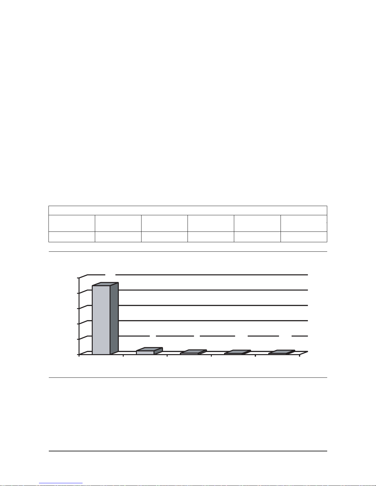
HD5 PROPANE
Propane Propylene Butane Iso-Butane Methane Total
(C3H8)(C
4H10
) (CH4)
90.0% min. up to 5% 2.0% 1.5% 1.5% 100%
90
5
2
1.5 1.5
0
20
40
60
80
100
%
Propane Propylene Butane Iso-butane Methane
HD5
LP Engine G430(3.0L) General Information

- 9 -
LP Engine G430(3.0L) General Information
1.3 Air Temperature Versus
Power Output
The temperature of the air entering an engine is
very important for two reasons.
1. Hot air entering an engine can lead to detonation
and pre-ignition, which will injure or destroy an
engine in short order. The cooler the temperature
of the incoming air the healthier it is for the
engine.
2. As the temperature of air entering an engine
increases it expands becoming less dense and
lighter. This reduces the volumetric efficiency
and therefore the horsepower output of the
engine. For every 10-degree increase of engine
intake air temperature the horsepower output
drops 1%. Since under hood air temperature can
easily reach 200 degrees it is very important that
the engine air intake be ducted outside the
engine
compartment. As an example an engine that makes
100 HP breathing air at 60 degrees will only make
86 horsepower breathing air at 200 degrees. This
decrease in power can be explained by the fact that
an engine requires 7lbs. of air to make 1
horsepower for 1 hour. As air is heated it expands
and becomes less dense and lighter (as in a hot air
balloon). A greater volume of air is required to
weight 7lbs. An engine running at rated full load
RPM can only breath a fixed volume of air. The
number of available pounds of air is reduced by
using hot air (a 100 cubic inch displacement 4
stroke engine will only pass 100 cubic inches of air
and fuel for every 2 revolutions of the crankshaft.
The displacement is fixed by the bore and stroke.
The displacement cannot increase to allow for the
high temperature and lower density of the incoming
air).
Intake Air Temperature vs Horse Power
00
2020
4040
6060
8080
100100
120120
5050
6060
7070
8080
9090
100100
110110
120120 130130
140140
150150
160160
170170
180180
190190
200200
210210
220220
230230
240240
250250
Temperature in Fahrenheit
Power(%)Power(%)
Air Temperature Versus Power Output

- 10 -
Altitude Versus Power Output
The altitude at which an engine operates has a
dramatic effect on power output. Since atmospheric
pressure (14.7psi at sea level) drops as altitude
increases air becomes less dense and lighter.
Therefore it has the same effect on horsepower
output as air temperature described in the previous
section. The rate of horsepower decrease is 3% for
each 1000 feet increase in altitude. As an example
an engine that makes 100 horsepower in
Washington, D.C. (elevation 30 feet) will only make
about 85 horsepower in Denver Colorado
(elevation 5280 feet).
An advantage to using gaseous fuels (LPG, CNG)
over liquid fuel (gasoline) is that when altitude
increases the density of air and gaseous fuels
change at about the same rate, therefore the air
fuel ratio remains unchanged. However with a
liquid fuel, as altitude increases, air becomes less
dense but the liquid fuel does not change therefore
the air fuel mixture becomes richer (less pounds of
air to a fixed amount of gasoline) and engine
horsepower output decreases more than the 3%
reduction (per 1000-feet) caused by the decrease
in atmospheric pressure.
0
20
40
60
80
100
120
-1 0.5 0 0.5 1 1.5 2 2.5 3 3.5 4 4.5 5 5.5 6 6.5 7 7.5 8 8.5 9 9.5 10
Altitude vs Hprse power
x1000 freet elevation
Power(%)Power(%)
LP Engine G430(3.0L) General Information
- 11 -
LP Engine G430(3.0L) General Information
General Description &
Operation
Engine Component Description
Engine Block
The engine block has four cylinders arranged in an “inline” construction. Starting at the front of the engine,
the cylinders are numbered 1-2-3-4. The firing order of
the cylinders is 1-3-4-2. The cylinders are encircled by
coolant jackets.
Cylinder Head
The cylinder head has one intake and one exhaust
valve per cylinder. A spark plug is located between the
valves in the side of the cylinder head. The valve
guides are integral and the valve rocker arms are
retained on individual threaded studs.
Crankshaft
The crankshaft is cast nodular iron and is supported
by five crankshaft bearings. The bearings are retained
by crankshaft bearing caps that are machined with the
engine block for proper alignment and clearances.
Camshaft
A billet steel one piece camshaft is supported by four
full round, sleeve-type bearings. These bearings are a
press fit into the engine block. The camshaft timing
sprocket is mounted to the front of the camshaft and is
driven the crankshaft sprocket.
Pistons and Connecting Rods
The pistons are made of cast-aluminum alloy using
two compression rings and one oil control ring
assembly. The piston pins are a press fit in the
connecting rods and a floating fit in the pistons.
Valve Train
The valve train is a ball-pivot type. Motion is
transmitted from the crankshaft through the valve lifter
and valve pushrod to the valve rocker arm. The valve
rocker arm pivots on its ball and transmits the
camshaft motion to the valve. The valve lifters keep all
parts of the valve train in constant contact. Each lifter
acts as an automatic adjuster and maintains zero lash
in the valve train. This eliminates the need for periodic
valve adjustment.
Lubrication
The oil pump is gear drive from the camshaft. Oil is
drawn from the oil pan through a pickup screen and
tube.
The gear type oil pump has a pressure regulator valve
which controls the lubrication system pressure by
bypassing excess oil back to the oil pan sump.
Pressurized oil from the oil pump flows to the full flow
filter.
A bypass valve allows oil to bypass the filter if it
becomes clogged or restricted. Oil then flows into an
oil passage that runs along the right side of the block
and intersects the lifter bosses. Oil from this passage
is routed to the crankshaft main bearings and
camshaft bearings through smaller drilled passages.
Oil is supplied to the connecting rod bearings by holes
drilled in the crankshaft. Oil is supplied to the rocker
arms through in the hydraulic lifters which feed oil up
the pushrods to the rocker arms.
The oil is metered by discs under the pushrod seat.
Many internal engine parts have no direct oil feed and
are supplied by either gravity or splash from other
direct feed components. Timing gears are lubricated
by oil supplied through a passage from the front of the
camshaft to a calibrated nozzle above the crankshaft
gear.
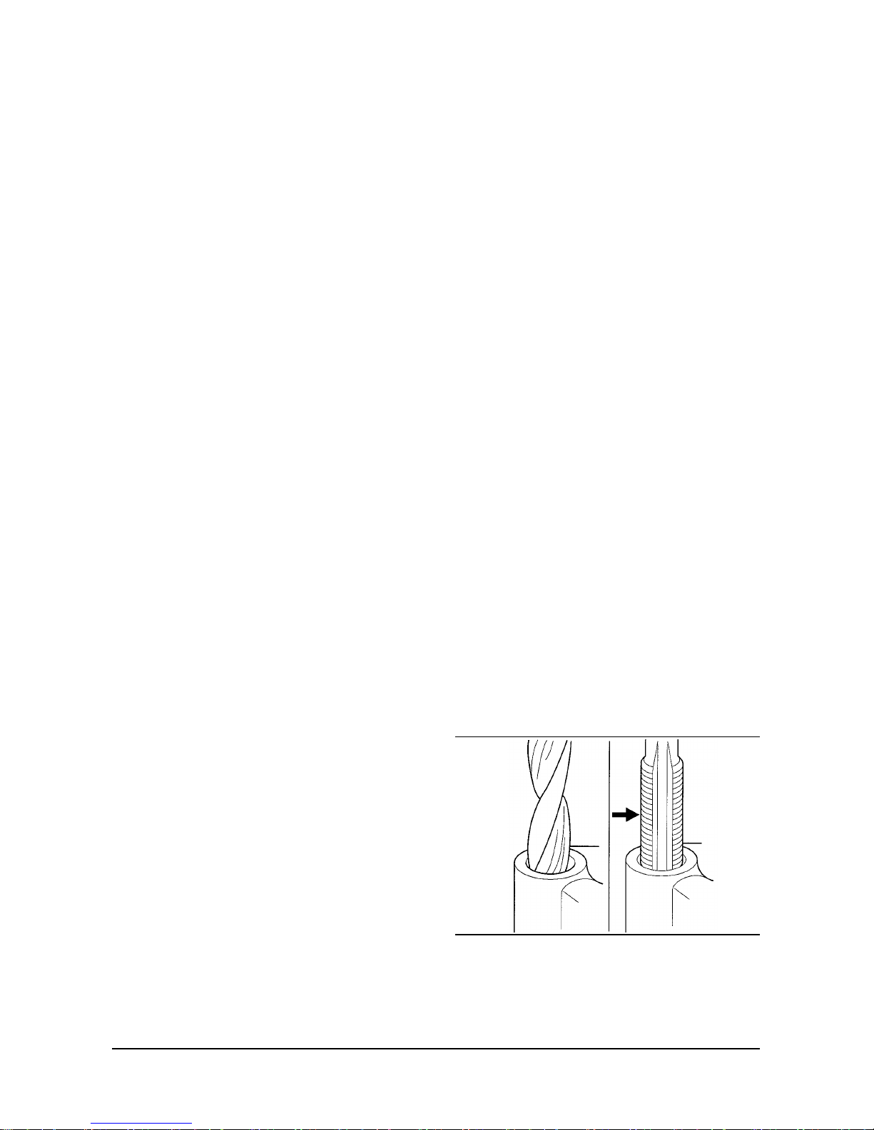
Thread Repair
Tools Required
General purpose thread repair kits. These kits are
available commerciall
y
VE121-3L
General Description & Operation

- 12 -
CAUTION: Wear safety glasses in order to avoid eye
damage.
1. Determine the size, pitch and depth of the damaged
thread. If necessary, adjust the stop collars on the
cutting tool and tap to the required depth.
2. Drill out the damaged thread. Clean out any chips.
3. Avoid any buildup of chips. Back out the tap every
few turns and remove the chips.
4. Tap the hole. Lubricate the tap with light engine oil.
Clean the thread.
5. Thread the insert onto the mandrel of the installer.
Engage the tang of the insert onto the end of the
mandrel.
IMPORTANT: The insert should be flush to one turn
below the surface.
6. Lubricate the insert with light engine oil (except
when installing in aluminum) and install the insert.
7. If the tang of the insert does not break off when
backing out the installer, break the tang off with a drift.
Cleanliness and Care
• Throughout this section, it should be understood that
proper cleaning and protection of machined surfaces
and friction areas is part of the repair procedure. This
is considered standard shop practice even if not
specifically stated.
• When any internal engine parts are serviced, care
and cleanliness is important.
• When components are removed for service, they
should be marked, organized or retained in a specific
order for reassembly. Refer to Separating Parts.
• At the time of installation, components should be
installed in the same location and with the same
mating surface as when removed.
• An engine is a combination of many machined,
honed, polished and lapped surfaces with tolerances
that are measured in millimeters or thousandths of
an inch. these surfaces should be covered or
protected to avoid component damage.
• Aliberal coating of clean engine oil should be applied
to friction areas during assembly.
• Proper lubrication will protect and lubricate friction
surfaces during initial operation.
Replacing Engine Gaskets
1. Gasket reuse and applying sealants:
• Do not reuse any gasket unless specified.
• Gaskets that can be reused will be identified in the
service procedure.
• Do not apply sealant to any gasket or sealing
surface unless specified in the service procedure.
2. Separating components:
• Use a rubber mallet to separate components.
• Bump the part sideways to loosen the components.
• Bumping should be done at bends or reinforced
areas to prevent distortion of the parts.
3. Cleaning gasket surfaces:
• Remove all gasket and sealing material from the
part using a plastic or wood scraper (if required).
• Care must taken to avoid gouging or scraping the
aluminum sealing surfaces.
• Do not use any other method or technique to
remove sealant or gasket material from a part.
• Do not use abrasive pads, sand paper or power
tools to clean gasket surfaces.
- These methods of cleaning can cause damage
to the component sealing surfaces.
- Abrasive pads also produce a fine grit that the oil
filter cannot remove from the oil.
- This grit is abrasive and has been known to
cause internal engine damage.
VE122-3L
LP Engine G430(3.0L) General Information

- 13 -
LP Engine G430(3.0L) General Information
4. Assembling components:
• When assembling components, use only the
sealant specified or equivalent in the service
procedure.
• Sealing surfaces should be clean and free of
debris or oil.
• Specific components such as crankshaft oil seals
or valve stem oil seals may require lubrication
during assembly.
• Components requiring lubrication will be identified
in the service procedure.
• When applying sealant to a component, apply the
amount specified in the service procedure.
• Do not allow the sealant to enter into any blind
threaded holes, as it may prevent the bolt from
clamping properly or cause component damage
when tightened.
• Tighten bolts to specifications. Do not overtighten.
Use of RTV and Anaerobic Sealer
IMPORTANT: Three types of sealer are commonly
used in engines. These are RTV sealer, anaerobic
gasket eliminator sealer and pipe joint compound. The
correct sealer and amount must be used in the proper
location to prevent oil leaks. DO NOT interchange the
three types of sealers. Use only the specific sealer or
the equivalent as recommended in the service
procedure.
Pipe Joint Compound
• Pipe joint compound is a pliable sealer that does not
completely harden. This type sealer is used where
two nonrigid parts (such as the oil pan and the
engine block) are assembled together.
• Do not use pipe joint compound in areas where
extreme temperatures are expected. These areas
include: exhaust manifolds, head gasket or other
surfaces where gasket eliminator is specified.
• Follow all safety recommendations and directions
that are on the container.
• To remove the sealant or the gasket material, Refer
to Replacing Engine Gaskets.
• Apply a continuous bead of pipe joint compound to
one sealing surface. Sealing surfaces to be resealed
must be clean and dry.
• Tighten the bolts to specifications. Do not overtighten.
RTV Sealer
• Room Temperature Vulcanizing (RTV) sealant
hardens when exposed to air. This type sealer is
used where two nonrigid parts (such as the oil pan
and the engine block) are assembled together.
• Do not use RTV sealant in areas where extreme
temperatures are expected. These areas include:
exhaust manifolds, head gasket or other surfaces
where gasket eliminator is specified.
• Follow all safety recommendations and directions
that are on the container.
• To remove the sealant or the gasket material, Refer
to Replacing Engine Gaskets.
• Apply RTV to a clean surface. Use a bead size as
specified in the service procedure. Run the bead to
the inside of any bolt holes. Do not allow the sealer
to enter any blind threaded holes, as it may prevent
the bolt from clamping properly or cause damage
when the bolt is tightened.
• Assemble components while RTV is still wet (within
three minutes) . Do not wait for RTV to skin over.
• Tighten the bolts to specifications. Do not
overtighten.
Anaerobic Sealer
• Anaerobic gasket eliminator hardens in the absence
of air. This type sealer is used where two rigid parts
(such as castings) are assembled and no sealer or
gasket is readily noticeable, the parts were probably
assembled using a gasket eliminator.
• Follow all safety recommendations and directions
that are on the container.
• To remove the sealant or the gasket material, Refer
to Replacing Engine Gaskets.
• Apply a continuous bead of gasket eliminator to one
flange. Surfaces to be resealed must be clean and
dry.
• Spread the sealer evenly with your finger to get a
uniform coating on the sealing surface. Do not allow
the sealer to enter any blind threaded holes, as it
may prevent the bolt from clamping properly or
cause damage when the bolt is tightened.
• Tighten the bolts to specifications. Do not
overtighten.
• After properly tightening the fasteners, remove the
excess sealer from the outside of the joint.

- 14 -
Separating Parts
IMPORTANT: Many internal engine components will
develop specific wear patterns on their
friction surfaces.
When assembling the engine, internal components
MUST be separated, marked or organized in a way to
ensure reinstallation to original location and position.
Mark or identify the following components:
• Piston and the piston pin.
• Piston assembly to the specific cylinder bore.
• Piston rings to the specific piston assembly and
cylinder bore.
• Connecting rod to the crankshaft journal.
• Connecting rod to bearing cap.
• Crankshaft main and connecting rod bearings.
• Camshaft and valve lifters.
• Valve lifters, guides, pushrods, pivot supports and
rocker arms.
• Valve to the valve guide.
• Valve spring and shim.
• Engine block main bearing cap location and
direction.
• Oil pump drive and driven gears.
Tools and Equipment
Special tools are listed and illustrated throughout this
section with a complete listing at the end of the
section.
These tools (or their equivalents) are specially
designed to quickly and safely accomplish the
operations for which they are intended. The use of
these special tools will also minimize possible damage
to engine components. Some precision measuring
tools are required for inspection of certain critical
components. Torque wrenches and a torque angle
meter are necessary for the proper tightening of
various fasteners.
To properly service the engine assembly, the
following items should be readily available:
• Approved eye protection and safety gloves.
• Aclean, well-lit work area.
• Asuitable parts cleaning tank.
• Acompressed air supply.
• Trays or storage containers to keep parts and
fasteners organized.
• An adequate set of hand tools.
• Approved engine repair stand.
• An approved engine lifting device that will
adequately support the weight of the components.
LP Engine G430(3.0L) General Information

- 15 -
LP Engine G430(3.0L) Specifications
SPECIFICATIONS
Technical Data
General Description
ENGINE TYPE: Inline 4-Cycle L4
COMBUSTION SYSTEM: Naturally Aspirated 1-Venturi Intake Manifold
EXHAUST SYSTEM: Cast Iron, Dry
VALVE CONFIGURATION: Pushrod Actuated Overhead Valves - 2 Per Cylinder
DISPLACEMENT: 2.967 cc (181 CID)
BORE: 101.60 mm (4.00 in.)
STROKE: 91.44 mm (3.60 in.)
COMPRESSION RATIO: 9.25:1
FIRING ORDER: 1-3-4-2
SPARK PLUGS: AC R46TS (0.045 in.)
WEIGHT: 165 Kg (363 lbs.) Dry (Base Engine)
ROTATION: Counter-Clockwise (CCW) When Viewed From Flywheel End
FUEL TYPE: LPG
Governed Speed: 2600
L 50 RPM
IDLE RPM: 800 L 25 RPM
TIMING: 0° BTDC at time position (1)
NOTE
(1)
: Base timing should be set with advance electronically locked out. Refer to timing procedures.
Fuel System
LP FUEL SYSTEM (STANDARD)
FUEL MIXER INLET PRESSURE: -51 mm Wg ±12.7 mm Wg (-2.0 in. WC ± 0.5 in. WC) @ Idle
GAS PRESSURE @ LPR INLET: Full Tank Pressure
Mixer: IMPCO 100 Series (1/2" NPT fuel inlet)
Recommended Regulator: IMPCO Model COBRA
Air/Fuel Mixture: 0.5 to 1.5% CO @ Rated Power and Speed
LP FUEL SYSTEM (Low Emission Version)
Mixer: IMPCO FB 60 Series
Regulator: IMPCO COBRA Series
Fuel Filtration Specification 40 Microns Maximum
Vacuum Hose, Check Valve to Regulator 9.5mm I.D.
Vacuum Hose, FCV to Throttle Body 4 mm I.D.
Fuel Hose, Regulator to Carburetor 15.9 mm I.D

- 16 -
Cooling System
WATER PUMP ROTATION: (viewed from front) w/V-Belt Drive - Clockwise (CW)
THERMOSTAT: LPG: Opening Temperature: 82°C (180°F)
Fully Open Temperature: 96°C (205°F)
COOLING WATER CAPACITY
(block only): 3.8 L (4.0 qts.)
Lubrication System
OIL PRESSURE (MIN. HOT): 28 kPa (4 psi) @ 700 RPM
124 kPa (18 psi) @ 2000 RPM
OIL TEMPERATURE: Upper Limit : 130°C (266°F)
Recommended : 99 - 110°C (210 - 230°F)
Lower Limit: 80°C (176°F)
CRANKCASE CAPACITY: Standard Pan : 3.8 L (4.0 qts.)
Oil Filter: 0.95 L (1 qt.)
ENGINE OIL SPECIFICATION: API - SG/SH, SAE 10W30 - All Temperatures
SAE 15W40 - Above -18°C (0°F)
SAE 30W - Between 5° and 27°C (40° and 80°F)
SAE 40W - Above 27°C (80°F)
Engine Electrical
IGNITION TYPE: Delco EST w/Electronic Advance
STARTER MOTOR: 12 Volt, 2.0 kW
ALTERNATOR: 12 Volt, 61 Amp
LP fuelock valve 12 volt
*
Oxygen Sensor Voltage Output : 0-1 volt (0.45 volt @ lambda =1)
*
Fuel Control Valve Operating Voltage : 12 volt
Coil resistance : 30 +/- 2 ohm
*
Switch, Vacuum MAP Set point : 23.7kPaG
*
Engine Control Unit(ECU) Electric connection information
Pin#1 Black Ground
Pin#5 Yellow Output, Fuel control valve control signal
Pin#6 Purple Output, Fuel control valve power
Pin#9 Green Input, Oxygen sensor
Pin#10 Blue Input MAP switch
Pin#11 White Input, Ignition tacho signal
Pin#12 Red Power (12 volt)
*
Low Emission Version Only
Exhaust System (Low Emission Version Only)
Catalytic muffler Three-way Catalyst included
LP Engine G430(3.0L) Specifications
- 17 -
LP Engine G430(3.0L) Specifications
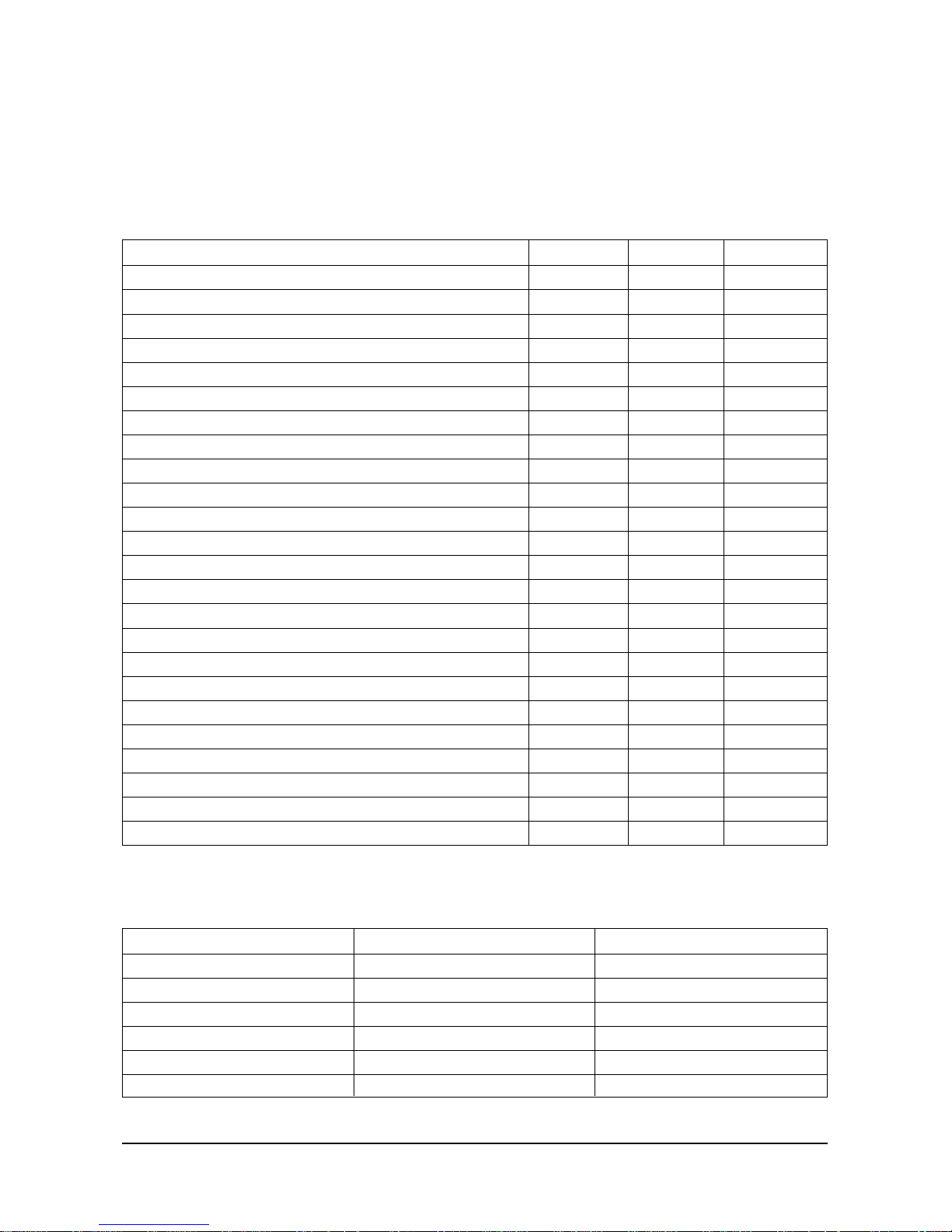
Engine Mechanical Data
Fastener Tightening Specifications
Sealers, Adhesives and Lubricants
Application N•m lb•ft lb•in
Camshaft Retainer Bolts 9 80
Connecting Rod Cap Nuts 61 45
Crankshaft Bearing Cap Bolts 75-95 55-70
Crankshaft Rear Oil Seal Retainer Nuts 17-20 150-180
Cylinder Head Bolts 122 90
Distributor Hold Down Bolt 27 20
Flywheel Bolts 88 65
Front Cover Bolts 3-4 27-35
Ignition Coil Bracket Attaching Bolts 22 16
Intake to Exhaust Manifold Attaching Nuts and Bolt 27-34 20-25
Intake/Exhaust Manifold to Head (2 center) 27-34 20-25
Intake/Exhaust Manifold to Head (outer) 20-27 15-20
Lift Bracket Bolts 27-41 20-30
Oil Pan Nuts (rear) 19 165
Oil Pan Bolts (to crankcase) 9 80
Oil Pan Bolts (to front cover) 5 45
Oil Pan Studs to Oil Seal Retainer or Crankcase 2 15
Oil Pump Cover 8 72
Oil Pump to Block 14 120
Oil Pump Pickup 7 60
Pushrod Cover Bolts 5 40
Rocker Arm Cover Bolts 5 40
Spark Plugs 30 22
Water Pump Bolts 20 15
GM Part Number
1052080
1052080
1052914
1052365
1052080
1052080
Type of Material
Sealant
Sealant
Sealant
Lubricant
Sealant
Sealant
Application
Rear camshaft bearing hole plug
Cylinder head bolt threads
Oil pan sealing surfaces
Valve train component prelube
Valve rocker arm stud threads
Oil level indicator tubea

- 18 -
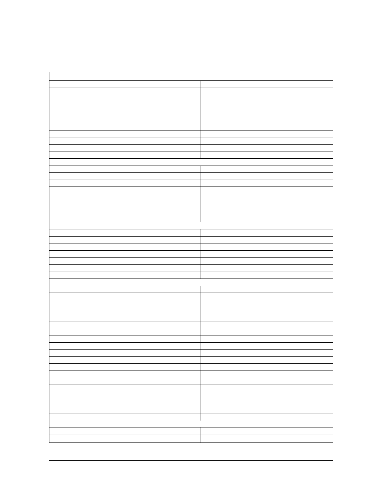
Engine Mechanical Specifications (1 of 2)
Application Metric English
General Data
Engine Type L4
Displacement 3.0L 181 CID
Bore 101.60 mm 4,000 in
Stroke 91.44 mm 3.60 in
Compression Ratio 9.25:1
Firing Order 1-3-4-2
Spark Plug Gap 0.9 mm 0.035 in
Lubrication System
Oil Pressure (Minimum-Hot) 41.4 kPa at 6.0 psig at
1,000 engine rpm 1,000 engine rpm
124.1 kPa at 18.0 psig at
2,000 engine rpm 2,000 engine rpm
165.5 kPa at 24.0 psig at
4,000 engine rpm 4,000 engine rpm
Oil Capacity 3.81 4.00 qts
Oil Pump Type Gear Driven
Cylinder Block
Bore Diameter 101.5873-101.6635 mm 3.9995-4.0025 in
Bore Out-of-Round Production 0.0254 mm (Maximum) 0.001 in (Maximum)
Bore Out-of-Round Service Limit 0.0508 mm (Maximum) 0.002 in (Maximum)
Bore Taper Thrust Side Production 0.0127 mm (Maximum) 0.0005 in (Maximum)
Bore Taper Thrust Side Service Limit 0.0254 mm (Maximum) 0.001 in (Maximum)
Bore Taper Relief Side Production 0.0127 mm (Maximum) 0.0005 in (Maximum)
Bore Taper Relief Side Service Limit 0.0254 mm (Maximum) 0.001 in (Maximum)
Runout-Rear Face of Block to Crankshaft Center Line 0.05 mm (Maximum) 0.002 in (Maximum)
Piston
Piston-To-Bore Clearance Production 0.0635-0.0889 mm 0.0025-0.0035 in
Piston-to-Bore Clearance Service Limit 0.0889 mm 0.0035 in (Maximum)
Piston Rings
Piston Compression Ring Groove Clearance Production Top
0.03048-0.07366 mm 0.0012-0.0029 in
Piston Compression Ring Groove Clearance Production 2nd
0.03048-0.07366 mm 0.0012-0.0029 in
Piston Compression Ring Groove Clearance Service Limit
0.09906 mm (Maximum) 0.0039 in (Maximum)
Piston Compression Ring Gap Top Production* 0.254-0.508 mm 0.01-0.02 in
Piston Compression Ring Gap 2nd Production* 0.4318-0.635 mm 0.017-0.025 in
Piston Compression Ring Gap Top Service Limit* 0.88 mm (Maximum) 0.035 in (Maximum)
Piston Compression Ring Gap 2nd Service Limit* 0.88 mm (Maximum) 0.035 in (Maximum)
Piston Oil Ring Groove Clearance Production 0.0254-0.1524 mm 0.001-0.006 in
Piston Oil Ring Groove Clearance Service Limit 0.1778 mm (Maximum) 0.007 in (Maximum)
Piston Oil Ring Gap Production* 0.25-0.76 mm 0.01-0.03 in
Piston Oil Ring Gap Service Limit* 1.016 mm (Maximum) 0.04 in (Maximum)
Piston Pin
Diameter 23.545-23.548 mm 0.9270-0.927 in
Clearance in Piston Production 0.00762-0.01651 mm 0.0003-0.00065 in
Clearance in Piston Service Limit 0.0254 mm (Maximum) 0.001 in (Maximum)
Fit in Connecting Rod 0.02032-0.050292 mm 0.0008-0.00198 in
(Interference) (Interference)
*Measured in cylinder bore
LP Engine G430(3.0L) Specifications
- 19 -
LP Engine G430(3.0L) Specifications
Engine Mechanical Specifications (2 of 2)
Crankshaft
Crankshaft Journal Diameter (All)
Crankshaft Journal Taper Production
Crankshaft Journal Taper Service Limit
Crankshaft Journal Out-of-Round Production
Crankshaft Journal Out-of-Round Service Limit
Crankshaft Bearing Clearance Production #1-#4
Crankshaft Bearing Clearance Production #5
Crankshaft Bearing Clearance Service Limit #1-#4
Crankshaft Bearing Clearance Service Limit #5
Crankshaft End Play
Crankshaft Sprocket Runout
Connecting Rod
Connecting Rod Journal Diameter
Connecting Rod Journal Taper Production
Connecting Rod Journal Taper Service Limit
Connecting Rod Journal Out-of-Round Production
Connecting Rod Journal Out-of-Round Service Limit
Rod Bearing Clearance Production
Rod Bearing Clearance Service Limit
Rod Side Clearance
Camshaft
Journal diameter
End Play
Camshaft Sprocket Runout
Timing Sprocket Teeth Backlash
Lobe Lift Intake
Lobe Lift Exhaust
Lobe Lift Service Limit
Valve System
Valve Lifter Hydraulic
Valve Rocker Arm Ratio 1.75:1
Valve Lash Half to One Turn Down From Zero Lash
Face Angle 45 Degrees
Seat Angle 46 Degrees
Seat Runout
Seat Width Intake
Seat Width Exhaust
Stem Clearance Intake Production
Stem Clearance Exhaust Production
Stem Clearance Intake Service Limit
Stem Clearance Exhaust Service Limit
Valve Spring Free Length
Valve Spring Pressure Closed
Valve Spring Pressure Open
Valve Spring Installed Height Intake
Valve Spring Installed Height Exhaust
Valve Lift Intake
Valve Lift Exhaust
Cylinder Head Warpage
Cylinder Head Deck (measured within a 152.4 mm (6.0 in) area)
Cylinder Head Deck (measuring the overall length of the cylinder head)
58.3666-58.4047 mm
0.005 mm (Maximum)
0.0254 mm (Maximum)
0.005 mm (Maximum)
0.0254 mm (Maximum)
0.0254-0.06096 mm
0.0406-0.0889 mm
0.0254-0.0635 mm
0.0381-0.0889 mm
0.05-0.1524 mm
0.07 mm (Maximum)
53.2892-53.3273 mm
0.00762 mm (Maximum)
0.0254 mm (Maximum)
0.005 mm (Maximum)
0.0254 mm (Maximum)
0.04318-0.06858 mm
0.0762 mm (Maximum)
0.1524-0.4318 mm
47.440-47.490 mm
0.0762-0.2032 mm
0.1 mm (Maximum)
0.10-0.15 mm
6.4247 mm
6.4247 mm
L 0.0254 mm
0.05 mm (Maximum)
1.27-1.778 mm
1.524-2.032 mm
0.0254-0.06858 mm
0.01778-0.06858 mm
0.09398 mm (Maximum)
0.1193 mm (Maximum)
52.324 mm
444-490 N at 40.89 mm
925-987 N at 30.99 mm
41.91 mm
41.91 mm
11.25 mm
11.25 mm
0.0762 mm
0.1778 mm
2.2979-2.2994 in
0.0002 in (Maximum)
0.001 in (Maximum)
0.0002 in (Maximum)
0.001 in (Maximum)
0.001-0.0024 in
0.0016-0.0035 in
0.001-0.0025 in
0.0015-0.0035 in
0.002-0.006 in
0.003 in (Maximum)
2.0980-2.0995 in
0.0003 in (Maximum)
0.001 in (Maximum)
0.0002 in (Maximum)
0.001 in (Maximum)
0.0017-0.0027 in
0.003 in (Maximum)
0.006-0.017 in
1.8677-1.8697 in
0.003-0.008 in
0.004 in (Maximum)
0.004-0.006 in
0.25294
0.25294
L 0.001 in
0.002 in (Maximum)
0.050-0.070 in
0.060-0.080 in
0.001-0.0027 in
0.0007-0.0027 in
0.0037 in (Maximum)
0.0047 in (Maximum)
2.06 in
100-110 lb at 1.61 in
208-222 lb at 1.22 in
1.65 in
1.65 in
0.443 in
0.443 in
0.003 in
0.007 in

- 20 -
MAINTENANCE
G430 Engine requires a certain amount of maintenance.
Suggested maintenance requirements are contained
in this section.
The owner should, however, develop his own maintenance schedule using the requirements listed in this
Section and any other necessary requirements
resulting from optional additions to the engine system.
Test fuel system for leaks
• Obtain a pump spray bottle.
• Fill with an approved leak test solution or a mixture
of water and dish soap.
• Spray a generous amount of the solution on the
entire fuel system including the fuel storage
container and fuel lines.
• Wait approximately 15-60 seconds then perform a
visual inspection of entire fuel system.
• Leaks will cause the soapysolution to bubble.
• Repair any leaks before continuing.
• Crank the engine throug several revolutions.
This will energize the fuel lock and allow fuel to flow
to the pressure regulator/vaporizer. Apply additional
leak test solution to this portion of the fuel system
and inspect as above.
• Repair any fuel leaks before continuing.
Inspect engine for fluid leaks
• Start engine and bring up to operating temperature.
• Turn engine off.
• Inspect entire engine for oil and/or coolant leaks.
• Repair any/all leaks before continuing.
Engine Crankcase Oil
Oil Recommendations
Prior to changing oil, select an oil based on the
prevailing daytime temperature in the area in which
the engine is operated. The chart in figure 2-1 is a
guide to selecting the proper crankcase oil. Refer
also to Lubrication System Section for additional
information.
IMPORTANT : Oils containing “solid” additives,
non-detergent oils, or low-quality oils are not
recommended for use in G430 Engine.
Figure 2-1 Engine Oil Viscosity Recommendation
Synthetic Oils
Synthetic engine oils are not recommended for use in
G430 Engine. Synthetics may offer advantages in
cold-temperature pumpability and high-temperature
oxidation resistance.
However, synthetic oils have not proven to provide
operational or economic benefits over conventional
petroleum-based oils in G430 Engine. Their use does
not permit the extension of oil change intervals.
LP Engine G430(3.0L) Maintenance

- 21 -
LP Engine G430(3.0L) Maintenance
Checking/Filling Engine Oil Level
IMPORTANT: Care must be taken when checking
engine oil level. Oil level must be maintained between
the "ADD" mark and the "FULL" mark on the dipstick.
To ensure that you are not getting a false reading,
make sure the following steps are taken before
checking the oil level.
Figure 2-2 Engine Oil Dipstick (Typical)
1. Stop engine if in use.
2. Allow sufficient time (approximately 5 minutes) for
the oil to drain back into the oil pan.
3. Remove dipstick. Wipe clean and reinstall.
Push dipstick all the way into the dipstick tube.
4. Remove dipstick and note the oil level.
5. Oil level must be between the "FULL" and "ADD"
marks (figure 2-2).
6. If the oil level is below the "ADD" mark, proceed to
Steps 7 and 8, and reinstall dipstick into the dipstick
tube.
7. Remove oil filler cap from the valve rocker arm
cover.
8. Add required amount of oil to bring level up to, but
not over, the "FULL" mark on dipstick.
CAUTION
Overfilled crankcases (oil level being too high) can
cause a fluctuation or drop in oil pressure and rocker
arm "clatter" on engines. The overfill condition results
in the engine crankshaft splash-ing and agitating the
oil, causing it to foam (become aerated). The aerated
oil causes the hydraulic valve lifters to "bleed down."
This, in turn, results in rocker arm "clatter"and loss of
engine performance due to the valves not opening
properly.
Changing Engine Oil And Filter
IMPORTANT : When changing the oil, always change
the oil filter.
1. Start engine and run until it reaches normal
operating temperatures.
IMPORTANT: Change oil when engine is warm from
operation as It flows more freely, carrying away more
impurities.
2. Stop engine.
3. Remove drain plug and allow all the oil to drain.
4. Remove and discard oil filter and its sealing ring.
5. Coat sealing ring on new filter with clean engine oil,
and install new filter. Tighten filter securely
(following filter manufacturer's instructions). Do not
overtighten.
6. Fill crankcase with oil.
7. Start engine and check for oil leaks.
Accessory Drive Belts
Engine must be shut off and the lgnltion key removed
before inspecting drive belts.
Check belt tension by pressing down on the midway
point of the longest stretch between two pulleys. The
belt should depress 1/2 in. (13mm). If depression is
more than allowable, adjust tension.
Inspect electrical system
• Clean battery outer surfaces with a mixture of baking
soda and water.
• Inspect battery outer surfaces for damage. Replace
as required.
• Remove battery cables and clean.
• Inspect battery cables for worn or missing
insulation, frayed wire and/or corrosion. Replace as
required.
131-160
WARNING
- 22 -
LP Engine G430(3.0L) Maintenance
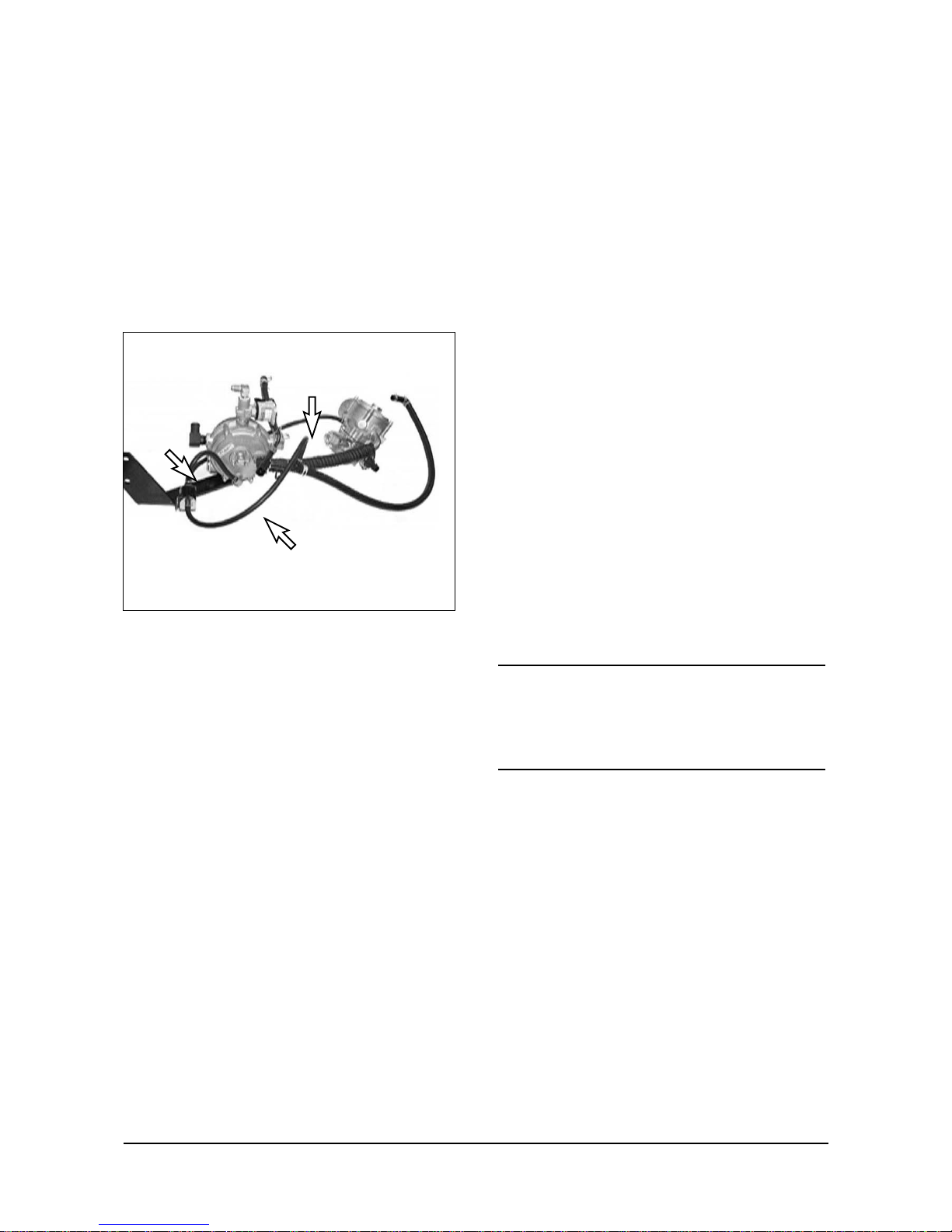
Inspect vacuum lines and fittings
●
Visually inspect vacuum lines and fittings for physical
damage such as brittleness, cracks, kinks and
misrouting. Repair/replace as required.
●
Solvent damage may cause vacuum lines to become
soft. Vacuum lines damaged by oil and/or other
solvents may collapse when the engine is running
effectively closing the passage inside the line.
Inspect fuel lines and fittings
●
Visually inspect fuel lines and fittings for physical
damage. Replace as required.
●
Fuel lines must be supported every 24inches.
●
Rubber grommets must be used where a fuel line
passes through sheet metal or similar material.
Engine Compression Check
1. Disconnect the primary lead from the distributor.
2. Remove all spark plugs.
3. Block the throttle plate and choke plate (if equipped)
into the wide-open position.
4. Make sure the battery is fully charged.
5. Starting with the compression gauge at zero, crank
the engine through four compression strokes.
6. Make the compression check at each cylinder and
record each reading.
7. If some cylinders have low compression, inject
about one tablespoon (15 ml or about three squirts
from a pump-type oil can) of engine oil into the
combustion chamber through the sparkplug hole.
Recheck compression.
8. Minimum compression recorded in any one cylinder
should not be less than 70% of the highest cylinder,
and no cylinder should read less than 100 psi (690
kPa). For example, if the highest pressure in any
one cylinder is 150 psi (1035 kPa), the lowest
allowable pressure for any other cylinder would be
105 psi (725 kPa), since 150 x 70% = 105 (1035 x
70% = 725).
●
Normal condition - compression builds up quickly
and evenly to the compression specified on each
cylinder.
●
Piston rings leaking - low compression on first stroke
tends to build up on following strokes but does not
reach normal. Improves considerably with addition of
oil.
●
Valves leaking - low compression on first stroke.
Does not tend to build up on following strokes. Does
not improve much with addition of oil.
●
If two adjacent cylinders have lower than normal
compression, and injecting oil into cylinders does not
increase the compres-sion, the cause may be a
head gasket leak between the cylinders.
Cooling System
CAUTION
Alcoholor methanol-based antifreeze or plain water
are not recommended for use in the cooling system at
anytime.
G430 Engine recommends that the cooling system be
filled with a 50/50 mixture of ethylene glycol antifreeze
and water.
G430 Engine can use any type of permanent
antifreeze or any brand antifreeze solution that meets
GM Specication 1825M or 1899M which will not
damage aluminum parts. Refer also to Cooling
System Section for additional information.
Checking coolant Level
Do not remove cooling system pressure cap when
engine is hot. Allow engine to cool and then remove
cap slowly allowing pressure to vent. Hot coolant
under pressure may discharge violently.
1. Check coolant level in coolant recover tank. Add

- 23 -
LP Engine G430(3.0L) Maintenance
specified coolant as required.
2. Periodically remove the pressure cap from the filler
neck to ensure the coolant recovery system is
functioning properly. Coolant must be at the top of
the filler neck. If coolant is low, check gasket in cap
for damage. Replace if mecessary. Inspect coolant
recovery system for leaks.
Inspect coolant hoses
●
Visually inspect coolant hoses and clamps.
●
Replace any hose that shows signs of swelling,
cracking, abrasion hardening or any other
damage/deterioration.
●
Top-up cooling system with approved coolant.
Inspect ignition system
●
Remove and inspect spark plugs.
Replace as required.
●
Test secondary wires with an Ohmmeter. Maximum
resistance repair replace as required.
●
Remove distributor cap and perform visual
inspection of distrbutor cap and rotor. Replace cap &
rotor if corrosion is found on contacts.
●
Inspect distributor breaker unit and housing for signs
of corrosion. Repair replace as required.
Replace spark plugs
●
Utilizing a gentle twisting motion remove the
secondary high voltage leads from the spark plugs.
Replace any damaged leads.
●
Remove the spark plugs.
●
Gap new spark plugs to proper specs.
●
Apply anti-seize compound to spark plug threads.
●
Install spark plugs.
●
Do not over tighten.
●
Install secondary high voltage leads.
Replace LP Fuel Filter Element
Park the lift truck in an authorized refueling area with
the forks lowered, parking beake applled and the
transmission in NEUTRAL.
1. Close the fuel shutoff valve on the LP-Gas tank.
Run the engine until fuel in the line runs out and the
engine stops. Turn off the ignition switch and
disconnect switch (if equipped).
2. Scribe a line across the filter housing covers.
3.Remove the cover retaining screws.

- 24 -
LP Engine G430(3.0L) Maintenance
4. Remove cover (5), magnet (4), spring (3) and
filter element (2) from bottom cover (1).
5. Replace the filter element (2).
6. Check bottom cover O-ring seal (6) for damage,
Replace it if necessary.
7. Install the filter element (2), spring (3), magnet
(4) and cover (5) on bottom cover (1). Align the
scribe line on the covers.
8. Install the cover retaining screws. Tighten the
screws in a sequence opposite each other.
9. Open the fuel valve by slowly turning the valve
counterclockwise.
10. Crank the engine only enough to produce a
vacuum at the fuelock. Turn the ignition key
switch off.
11. Check the fuel lines and fittings for leaks with a
soap solution. Make repairs if necessary.
Test fuel lock (electric)
●
Start engine.
●
Locate electrical connector for fuel lock.
●
Disconnect electrical connector.
●
Engine will run out of fuel and stop in a short period
of time. (The length of time increases with any
increase in distance between the fuel lock and the
pressure regulator).
Inspect pressure
regulator/vaproizer
See, pressure regulator/vaporizer in LP fuel system
section
Inspect LP mixer
(standard LP truck)
See, LP mixer in LP fuel system section.
Inspect variable venturi air/fuel
mixer (low emission LP truck)
See, Variable Venturi Air/Fuel Mixer in LP fuel system
(Low emission version) section.
Inspect complete exhaust
system for leaks, damage
●
Pertorm Visual inspection of exhaust system.
●
Repair any/all leaks found.
Engine Control Unit (ECU) and
others (low emission LP truck)
The commander, oxygen sensor and vacuum control
solenoid are not serviceable. If faulty, they must be
replaced. See Trouble Shooting Section.
5
4
3
2
1
6

- 25 -
LP Engine G430(3.0L) Maintenance
Maintenance Schedule
CHECK POINT
General Maintenance Section
Test fuel system for leaks Prior to any service of maintenance activity
Inspect engine for fluid leaks O
Check engine oil and filter O
Change engine oil and filter O
Inspect accessory drive belts O
Inspect electrical system O
Inspect all vacuum lines and fittings O
Inspect all fuel fittings and hoses O
Check engine compression pressure O
Engine Coolant Section
Check coolant level O
Change coolant O
Inspect coolant hoses for leaks, cracks swelling, or deterioration O
Engine Ignition Section
Inspect battery for case damage and corroded Cables O
Inspect ignition system O
Check ignition timing-adjust as necessary O
Replace spark plugs O
Fuel Lock-Off/Filter Section
Replace LP fuel filter element O
Inspect lock-off and filter for fuel leaks O
Ensure lock-off stops fuel flow when engine is off O
Pressure Regulator Section
Test regulator pressures O
Inspect pressure regulator for oil build-up O
Inspect pressure regulator assembly for fuel/coolant leaks O
Carburetor Section
Check for air leaks in filter system O
Check for vacuum leaks on complete intake system O
Inspect air/gas valve assembly O
Inspect air/fuel mixture throat O
Check air cleaner indicator O
Inspect air cleaner O
Replace air filter elementO O
Engine Exhaust Section (Low Emission Version only)
Inspect exhaust manifold for leaks O
Inspect manifold-to-catalyst exhaust piping and Connections for leaks O
Inspect catalyst inlet and outlet and leaks O
Daily
Every
250hrs
or
a month
Every
500hrs
or
3months
Every
1000hrs
or
6months
Every
2000hrs
or
year
Every
3000hrs
or
18months
Interval Hours

- 26 -
LP Engine G430(3.0L) Troubleshooting
TROUBLESHOOTING
Engine Performance
Symptom Cause
1. Poor engine idle. A. Clogged air breather.
B. Improper idle-fuel mixture adjustment.
C. Cap or spark-plug wires arcing.
D. Low grade fuel.
E. Incorrect ignition timing.
F. Spark plugs (fouled, burned, cracked porcelain).
G. Spark plug wires broken or faulty insulation.
H. Defective coil.
I. Cracked or dirty distributor cap.
J. Dirty carburetor.
K. Leak at intake manifold or carburetor base.
L. Low compression. (Check for blown head gasket).
M. Loose or worn distributor.
N. Head gasket, exhaust manifold, cracked head or valve seat.
2. Poor engine acceleration. A. Idle mixture screw.
B. Incorrect ignition timing.
C. Incorrect distributor advance curve.
D. Cracked or dirty distributor cap or rotor.
E. Vacuum leak on the intake manifold or carburetor base.
F. Spark plugs (fouled, burned, wrong heat range, cracked porcelain).
G. Dirty carburetor.
H. Low compression.
Engine Starting Problems
The following information will help to locate the starting problem:
1. Determine which engine system is causing the problem. To make an engine run, basic components - fuel, spark
(ignition) and compression - are required. If all three components are present, the engine should run. If any one
of the three is missing, weak or arriving at the wrong time, the engine will not run.
2. Determine if there is fuel present.
3. Check ignition system operation. Using appropriate spark tester, check for spark at coil and at each spark plug.
If there is a spark at the spark plug wires, remove the spark plugs and make sure they are the correct type and
heat range, and not fouled or burned.
4. Run a compression check on the engine to make sure it is mechanically sound.

- 27 -
LP Engine G430(3.0L) Troubleshooting
Engine Starting Problems (Continued)
Symptom Cause
1. No spark. A. Distributor cap or spark plug leads arcing.
B. Spark plugs fouled, burned or cracked porcelain.
C. Spark plug wires are broken or have faulty insulation.
D. Battery, electrical connections, damaged wiring.
E. Ignition switch.
F. Faulty ignition components.
G. Cracked or dirty distributor cap.
H. Shorted tachometer. (Disconnect tachometer and try again).
2. Engine will not crank over. A. Battery charge low, damaged wiring or loose electrical connections.
B. Circuit breaker tripped (if equipped).
C. Bad ignition switch.
D. Bad starter solenoid.
E. Defective starter motor.
Charging System Problems
Symptom Cause
1. Gauges indicate no A. Loose or broken drive belt.
battery charge. B. Loose or corroded electrical connections.
C. Faulty ammeter or voltmeter.
D. Battery will not accept charge.
E. Faulty alternator or regulator.
2. Noisy alternator. A. Loose mounting bolts.
B. Worn, frayed or loose drive belt.
C. Loose drive pulley.
D. Worn or dirty bearings.
E. Faulty diode trio or stator.
Instrument Problems
Symptom Cause
1. Malfunctioning A. Faulty wiring, loose or corroded terminals.
instruments or gauges. B. Bad key switch.
C. Faulty gauge.
D. Faulty sender.

- 28 -
LP Engine G430(3.0L) Troubleshooting
Engine Noise
No definite rule or test will positively determine the
source of engine noise. Therefore, use the following
information only as a general guide to engine noise
diagnosis.
1. Use a timing light to determine if noise is timed with
engine rpm or one-half engine rpm. Noises timed
with engine rpm are related to crankshaft, rods,
pistons, piston pins or flywheel. Noises timed to
one-half engine rpm are valve-train related.
2. The use of a stethoscope can aid in locating a noise
source. However, because noise will travel to other
metal parts not involved in the problem, caution
must be exercised.
3. If noise is believed to be confined to one particular
cylinder, ground the spark plug leads one at a time.
If noise lessens noticeably or disappears, it is
isolated to that particular cylinder.
4. Try to isolate the noise to location in engine, front to
back, top to bottom. This can help determine which
components are at fault.
5. Sometimes noises can be caused by moving parts
coming in contact with other components.
Examples are: flywheel, crankshaft striking (pan
and pan baffle), rocker arm striking valve cover or
loose flywheel cover. In many cases, if this is found
to be the problem, a complete engine teardown is
not necessary.
6. When noise is isolated to a certain area and
component, removal and inspection will be
required. Refer to proper sections of service manual
for pertinent information.
Symptom Cause
1. Noise around the A. Rocker arm striking valve cover.
valve cover area. B. Rocker arm out of adjustment.
C. Worn rocker arm.
D. Bent push rod.
E. Collapsed lifter.
2. Noise around the A. Sticking valve.
cylinder area. B. Carbon build-up.
C. Connecting rod installed wrong.
D. Bent connecting rod.
E. Piston.
F. Piston rings.
G. Piston pin.
H. Cylinder worn.
3. Noise around camshaft A. Loss of oil pressure.
area (throughout engine). B. Valve lifters.
C. Cam bearings.
4. Noise in camshaft area A. Camshaft timing gear.
area (front of engine). B. Timing chain.
C. Fuel pump.
D. Valve lifter.
E. Cam bearings.

- 29 -
LP Engine G430(3.0L) Troubleshooting
Engine Noise (Continued)
Symptom Cause
5. Noise in camshaft area A. Valve lifter.
(center of engine). B. Cam bearings.
6. Noise in camshaft area A. Distributor gear.
(rear of engine). B. Valve lifter.
C. Cam bearings.
7. Noise in crankshaft area A. Loss of oil pressure.
(throughout engine). B. Main bearings.
C. Rod bearings.
8. Noise in crankshaft area A. Crankshaft timing gear.
(front of engine). B. Timing chain.
C. Main bearing.
D. Rod bearing.
9. Noise in crankshaft area A. Crankshaft striking pan or pan baffle.
(center of engine). B. Main bearing.
C. Rod bearing.
10. Noise in crankshaft area A. Loose flywheel cover.
(rear of engine). B. Loose flywheel.
C. Drive plate.
D. Main bearing.
E. Rod bearing.
11. Engine spark knock. A. Advanced timing.
B. Low quality fuel.
C. Engine running hot.
D. Carbon deposits in engine.
12. Popping through A. Wrong ignition timing.
carburetor. B. Carburetor set too lean.
C. Faulty accelerator pump (gasoline).
D. Vacuum leak.
E. Valve adjustment.
F. Valve timing.
G. Burned or stuck valve.
13. Hissing. A. Vacuum leak.
B. Leaking exhaust (manifolds or pipes).
C. Loose cylinder heads.
D. Blown head gasket.
14. Whistle. A. Vacuum leak.
B. Dry or tight bearing in an accessory.
15. Sparks jumping. A. Defective high-tension cables.
B. Cracked coil tower.
C. Cracked distributor cap.
16. Squeaks or squeals. A. Drive belt slipping.
B. Dry or tight bearing in an accessory.
C. Parts rubbing together.
 Loading...