

Doosan G70WJD-2A-T3, G145WJD-2A-T3, G25WMI-2A-T2, G185WJD-2A-T3, G240WJD-2B-T3 Installation, Operation & Maintenance Manual
...
OPERATION, MAINTENANCE
MANUAL
G10WMI-2D-T2 (B63)
G25WMI-2A-T2 (B54)
G40WMI-2A-T2 (B50)
G60WJD-2A-T2 (B55)
G70WJD-2A-T3 (D63)
G80
G90WJD-2A-T3 (C24)
G125
G145WJD-2A-T3 (C27)
G185WJD-2A-T3 (C28)
G240WJD-2B-T3 (C31)
G240WCU-2C-T3 (D97)
G290WCU-3B-T3 (C38)
G290WCU-3C-T3 (D77)
G450WCU-2B-T2 (C34)
G450WCU-2C-T2 (D96)
G570WCU-2B-T2 (C37)
G570WCU-2C-T2 (D78)
GENERATOR MODELS
This manual contains important safety information.
Do not destroy this manual.
This manual must be available to the personnel who operate and maintain this machine.
Doosan Infracore Portable Power
1293 Glenway Drive
Statesville, N.C. 28625
www.doosanportablepower.com
Book: 22637300 (8-2-2010) Rev H

2

TABLE OF CONTENTS
Operation & Maintenance Manual
TITLE PAGE
DRAWBAR NOTICE. . . . . . . . . . . . . . . . . . . . . . . . . . . . . . . . . . . . . . . . . . . . . . . . . . . . . 5
SAFETY SYMBOLS . . . . . . . . . . . . . . . . . . . . . . . . . . . . . . . . . . . . . . . . . . . . . . . . . . . . . 7
SAFETY . . . . . . . . . . . . . . . . . . . . . . . . . . . . . . . . . . . . . . . . . . . . . . . . . . . . . . . . . . . . . . 13
HAZARDOUS SUBSTANCE PRECAUTION . . . . . . . . . . . . . . . . . . . . . . . . . . . . . . . . . . . . . . . . . . 20
GENERAL DATA . . . . . . . . . . . . . . . . . . . . . . . . . . . . . . . . . . . . . . . . . . . . . . . . . . . . . . . 21
Unit Model: . . . . . . . . . . . . . . . . . . . . . . . . . . . . . . . . . . . . . . . . . . . . . . . . . . . . . . . . . . . . . . . . . . . . 22
Unit Model: . . . . . . . . . . . . . . . . . . . . . . . . . . . . . . . . . . . . . . . . . . . . . . . . . . . . . . . . . . . . . . . . . . . . 23
Unit Model: . . . . . . . . . . . . . . . . . . . . . . . . . . . . . . . . . . . . . . . . . . . . . . . . . . . . . . . . . . . . . . . . . . . . 24
Consumables Service Parts:. . . . . . . . . . . . . . . . . . . . . . . . . . . . . . . . . . . . . . . . . . . . . . . . . . . . . . . 25
Consumable Service Parts:. . . . . . . . . . . . . . . . . . . . . . . . . . . . . . . . . . . . . . . . . . . . . . . . . . . . . . . . 26
Expendable Service Parts: . . . . . . . . . . . . . . . . . . . . . . . . . . . . . . . . . . . . . . . . . . . . . . . . . . . . . . . . 27
OPERATING INSTRUCTIONS. . . . . . . . . . . . . . . . . . . . . . . . . . . . . . . . . . . . . . . . . . . . . 29
BEFORE TOWING . . . . . . . . . . . . . . . . . . . . . . . . . . . . . . . . . . . . . . . . . . . . . . . . . . . . . . . . . . . . . . 30
TOWING . . . . . . . . . . . . . . . . . . . . . . . . . . . . . . . . . . . . . . . . . . . . . . . . . . . . . . . . . . . . . . . . . . . . . . 31
SETTING UP. . . . . . . . . . . . . . . . . . . . . . . . . . . . . . . . . . . . . . . . . . . . . . . . . . . . . . . . . . . . . . . . . . . 31
DISCONNECT . . . . . . . . . . . . . . . . . . . . . . . . . . . . . . . . . . . . . . . . . . . . . . . . . . . . . . . . . . . . . . . . . 31
BEFORE STARTING . . . . . . . . . . . . . . . . . . . . . . . . . . . . . . . . . . . . . . . . . . . . . . . . . . . . . . . . . . . . 32
STARTING (AUTOSTART MODELS). . . . . . . . . . . . . . . . . . . . . . . . . . . . . . . . . . . . . . . . . . . . . . . . 33
STOPPING (AUTOSTART MODELS) . . . . . . . . . . . . . . . . . . . . . . . . . . . . . . . . . . . . . . . . . . . . . . . 34
REMOTE STARTING AND STOPPING . . . . . . . . . . . . . . . . . . . . . . . . . . . . . . . . . . . . . . . . . . . . . 34
DIAGNOSTICS/AUTO SHUTDOWN (AUTOSTART MODELS). . . . . . . . . . . . . . . . . . . . . . . . . . . . 35
ENGINE CONTROLS and INSTRUMENTS (AUTOSTART MODELS) . . . . . . . . . . . . . . . . . . . . . . 35
CUSTOMER - DIAGNOSTIC GAUGE OPERATION . . . . . . . . . . . . . . . . . . . . . . . . . . . . . . . . . . . . 37
STARTING (KEY START MODELS) . . . . . . . . . . . . . . . . . . . . . . . . . . . . . . . . . . . . . . . . . . . . . . . . 38
STOPPING (KEYSTART MODELS). . . . . . . . . . . . . . . . . . . . . . . . . . . . . . . . . . . . . . . . . . . . . . . . . 40
DIAGNOSTICS and AUTO SHUTDOWN (KEYSTART MODELS). . . . . . . . . . . . . . . . . . . . . . . . . . 40
ENGINE CONTROLS and INSTRUMENTS (Keystart Models) . . . . . . . . . . . . . . . . . . . . . . . . . 41
GENERATOR SYSTEM . . . . . . . . . . . . . . . . . . . . . . . . . . . . . . . . . . . . . . . . . . . . . . . . . . . . . . . . . . 42
MONITOR SWITCHES. . . . . . . . . . . . . . . . . . . . . . . . . . . . . . . . . . . . . . . . . . . . . . . . . . . . . . . . 42
CIRCUIT BREAKERS - Flip to Reset (if equipped) . . . . . . . . . . . . . . . . . . . . . . . . . . . . . . . . . . 43
RECEPTACLES (if equipped) . . . . . . . . . . . . . . . . . . . . . . . . . . . . . . . . . . . . . . . . . . . . . . . . . . 43
PROTECTION/REGULATION . . . . . . . . . . . . . . . . . . . . . . . . . . . . . . . . . . . . . . . . . . . . . . . . . . 43
VOLTAGE SELECTION/ADJUSTMENTS G25 thru G185 . . . . . . . . . . . . . . . . . . . . . . . . . . . . . . . . 44
SWITCH POSITION - 120/208V 3 Phase. . . . . . . . . . . . . . . . . . . . . . . . . . . . . . . . . . . . . . . . . . . . . 45
SWITCH POSITION - 277/480V 3 Phase. . . . . . . . . . . . . . . . . . . . . . . . . . . . . . . . . . . . . . . . . . . . . 45
SWITCH POSITION - 120/240 1Phase . . . . . . . . . . . . . . . . . . . . . . . . . . . . . . . . . . . . . . . . . . . . . . 46
VOLTAGE SELECTION/ADJUSTMENTS G240 thru G570 . . . . . . . . . . . . . . . . . . . . . . . . . . . . . . . 47
120/208V 3 Phase. . . . . . . . . . . . . . . . . . . . . . . . . . . . . . . . . . . . . . . . . . . . . . . . . . . . . . . . . . . . . . . 49
277/480V 3 Phase. . . . . . . . . . . . . . . . . . . . . . . . . . . . . . . . . . . . . . . . . . . . . . . . . . . . . . . . . . . . . . . 49
BASIC DIGITAL CONTROLS OPERATION. . . . . . . . . . . . . . . . . . . . . . . . . . . . . . . . . . . . . . . . . . . 50
3

TABLE OF CONTENTS
Operation & Maintenance Manual
TITLE PAGE
MAINTENANCE . . . . . . . . . . . . . . . . . . . . . . . . . . . . . . . . . . . . . . . . . . . . . . . . . . . . . . . . 65
General . . . . . . . . . . . . . . . . . . . . . . . . . . . . . . . . . . . . . . . . . . . . . . . . . . . . . . . . . . . . . . . . . . . . . . . 66
Scheduled Maintenance . . . . . . . . . . . . . . . . . . . . . . . . . . . . . . . . . . . . . . . . . . . . . . . . . . . . . . . . . . 66
ADJUSTMENT INSTRUCTIONS and TESTING PROCEDURES . . . . . . . . . . . . . . . . . . . . . . . . . . 71
ACCESSING COMPARTMENT . . . . . . . . . . . . . . . . . . . . . . . . . . . . . . . . . . . . . . . . . . . . . . . . . 71
VOLTAGE REGULATOR ADJUSTMENT . . . . . . . . . . . . . . . . . . . . . . . . . . . . . . . . . . . . . . . . . 71
OVERCURRENT RELAY ADJUSTMENT (Set Dial on the OCR Relay) . . . . . . . . . . . . . . . . . . . . . 72
POWER BYPASS SWITCH FOR ENGINE ECU SERVICE. . . . . . . . . . . . . . . . . . . . . . . . . . . . 73
PACKAGE PREVENTIVE MAINTENANCE SCHEDULE. . . . . . . . . . . . . . . . . . . . . . . . . . . . . . 74
ALTERNATOR INSTALLATION AND MAINTENANCE . . . . . . . . . . . . . . . . . . . . . . . . . 75
SAFETY MEASURES. . . . . . . . . . . . . . . . . . . . . . . . . . . . . . . . . . . . . . . . . . . . . . . . . . . . . . . . . . . . 76
INSTALLATION - COMMISSIONING . . . . . . . . . . . . . . . . . . . . . . . . . . . . . . . . . . . . . . . . . . . . . . . . 83
SERVICING-MAINTENANCE. . . . . . . . . . . . . . . . . . . . . . . . . . . . . . . . . . . . . . . . . . . . . . . . . . . . . .88
TECHNICAL CHARACTERISTICS. . . . . . . . . . . . . . . . . . . . . . . . . . . . . . . . . . . . . . . . . . . . . . . . . . 94
4

Drawbar Notice
22637300 5
Operation & Maintenance Manual Drawbar Notice
Drawbar Notice
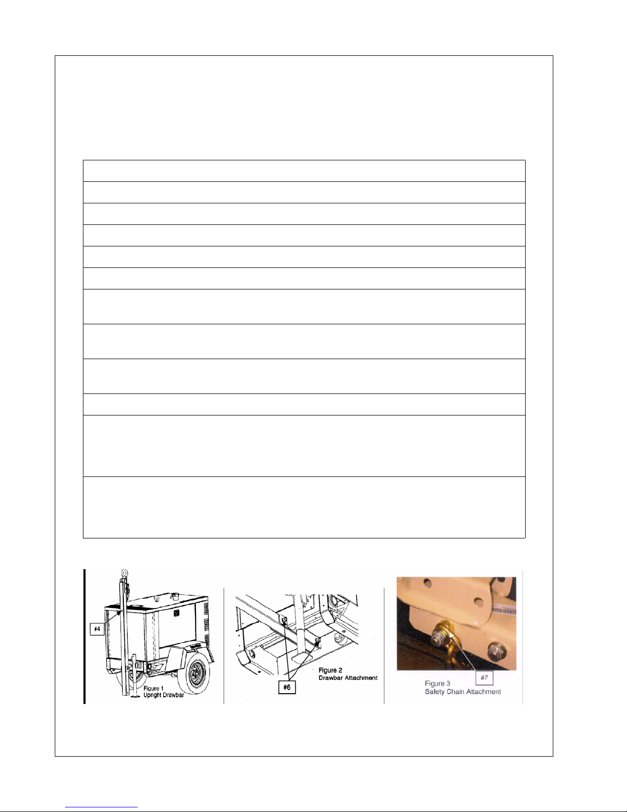
This machine may have been shipped from the factory with the drawbar positioned upright. To
convert from shipping position to towing position, the following tools are required:
Tool Required:
Ratchet, 24mm socket and an 18mm socket to fit ratchet
Torque wrench set to 166 ft-lbs (226 Nm) and 67 ft-lbs. (91 Nm)
24mm socket and an 18mm socket to fit torque wrench
Hardware included: (1) 16mm nut, (2) Washers, (2) Safety Chains
1. Remove hardware box from generator.
2. Open box and remove the bag containing hardware, safety chains and assembly
instructions.
3. Using the jack, raise the front of the unit so that the end of the drawbar is
approximately 1 inch above the ground.
4. While holding the drawbar, carefully remove the temporary retaining bolt that holds
the drawbar to the top of the enclosure (See Fig. 1).
5. Carefully lower drawbar to the Level Position.
6. Install the bolt (that was removed in Step 4) with the washers and nut from the
included hardware to secure the end of the drawbar underneath the unit and torque to
166 ft-lbs (226 Nm). Also torque the drawbar pivot bolt to 166 ft-lbs. (226 Nm). See
Figure 2).
7. Install safety chains by first removing the longest bolt used to attach the hitch then
insert the last link of one chain onto the bolt. Slide one spa cer back on the bo lt and pu t
the assembly back into the hitch. Slide the other spacer onto th e bolt, th en the last link
of the other safety chain washer. Tighten the nut to 67 ft-lbs (91 Nm).
6 22637300

Safety Symbols
22637300 7
Operation & Maintenance Manual Safety Symbols
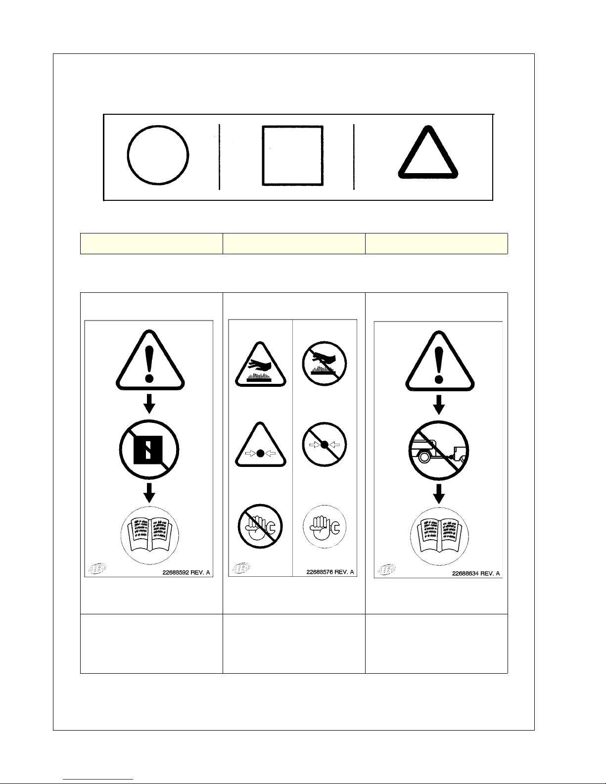
Symbols below point out potential safety hazards and provide important information about this
machine. Read and understand. Heed warnings and follow instructions. If you do not
understand, inform your supervisor.
Prohibition/ Mandatory Information/Instructions WARNING
WARNING - Read the
operator’s manual before
operating this machine.
WARNING - Do not open
radiator until radiator is
cool and pressure is
WARNING - Read the
operator’s manual before
towing machine.
relieved.
8 22637300
Safety Symbols Operation & Maintenance Manual
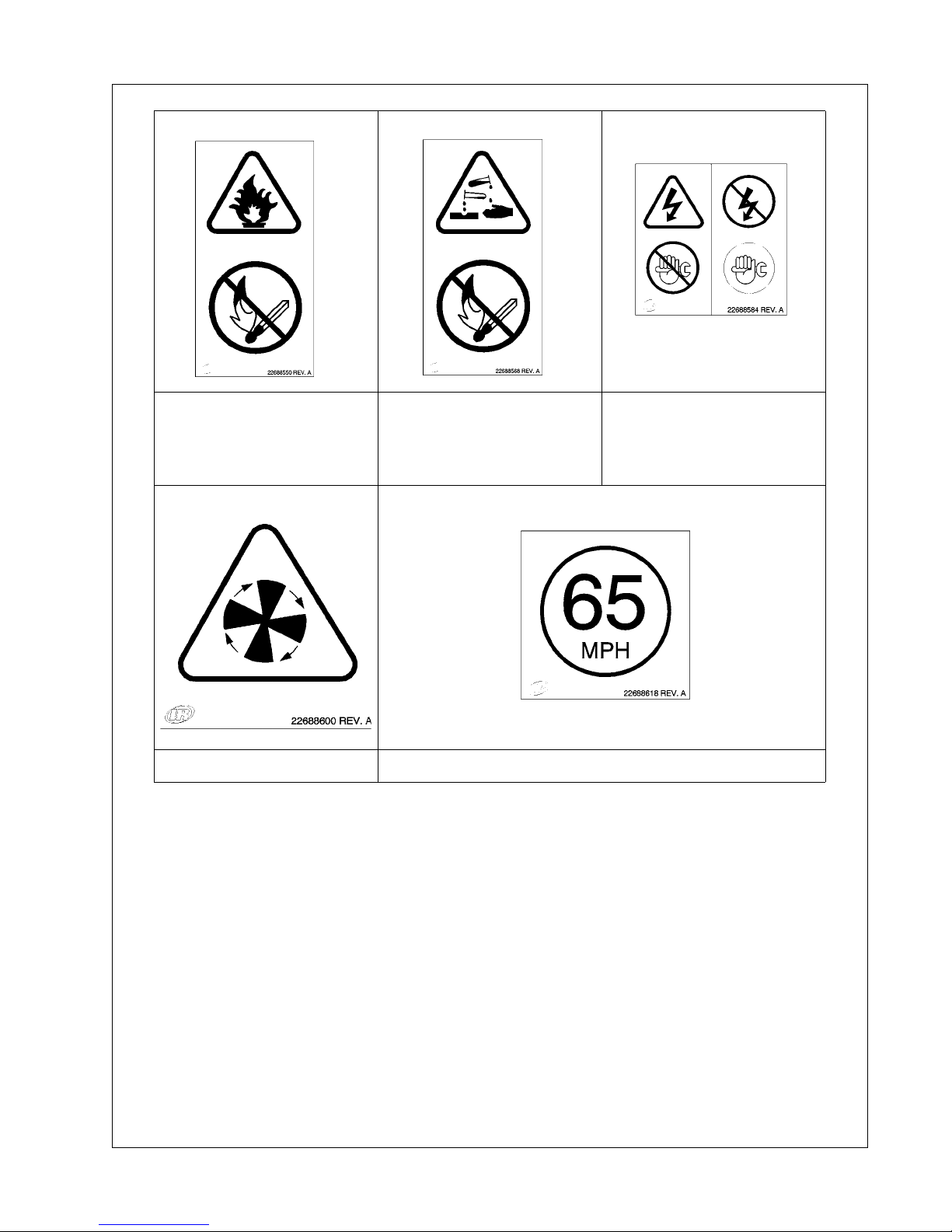
WARNING - Diesel fuel is
flammable. No open
flames or sparks.
WARNING - Battery
contains acid. Gases are
flammable. No open
flames or sparks.
WARNING - Do not
perform maintenance until
all electrical power has
been disconnected.
WARNING - Rotating fan. 65 MPH maximum towing speed.
22637300 9
Operation & Maintenance Manual Safety Symbols
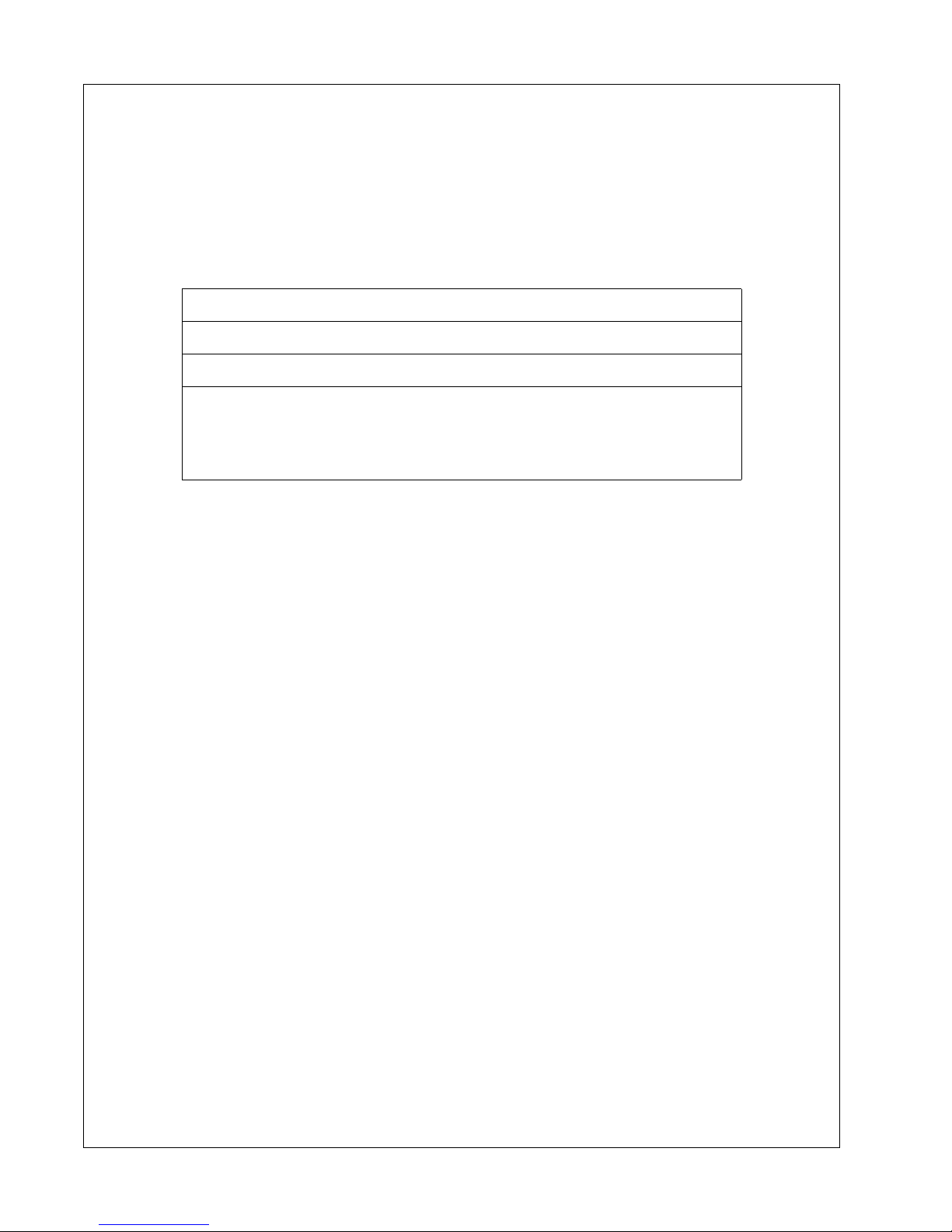
Safety Symbols
Look for these signs on machines manufactured in North America, which point out
potential hazards to the safety of you and others. Read and understand thoroughly.
Heed warnings and follow instructions. If you do not understand, inform your
supervisor.
Safety Decals area available free of charge.
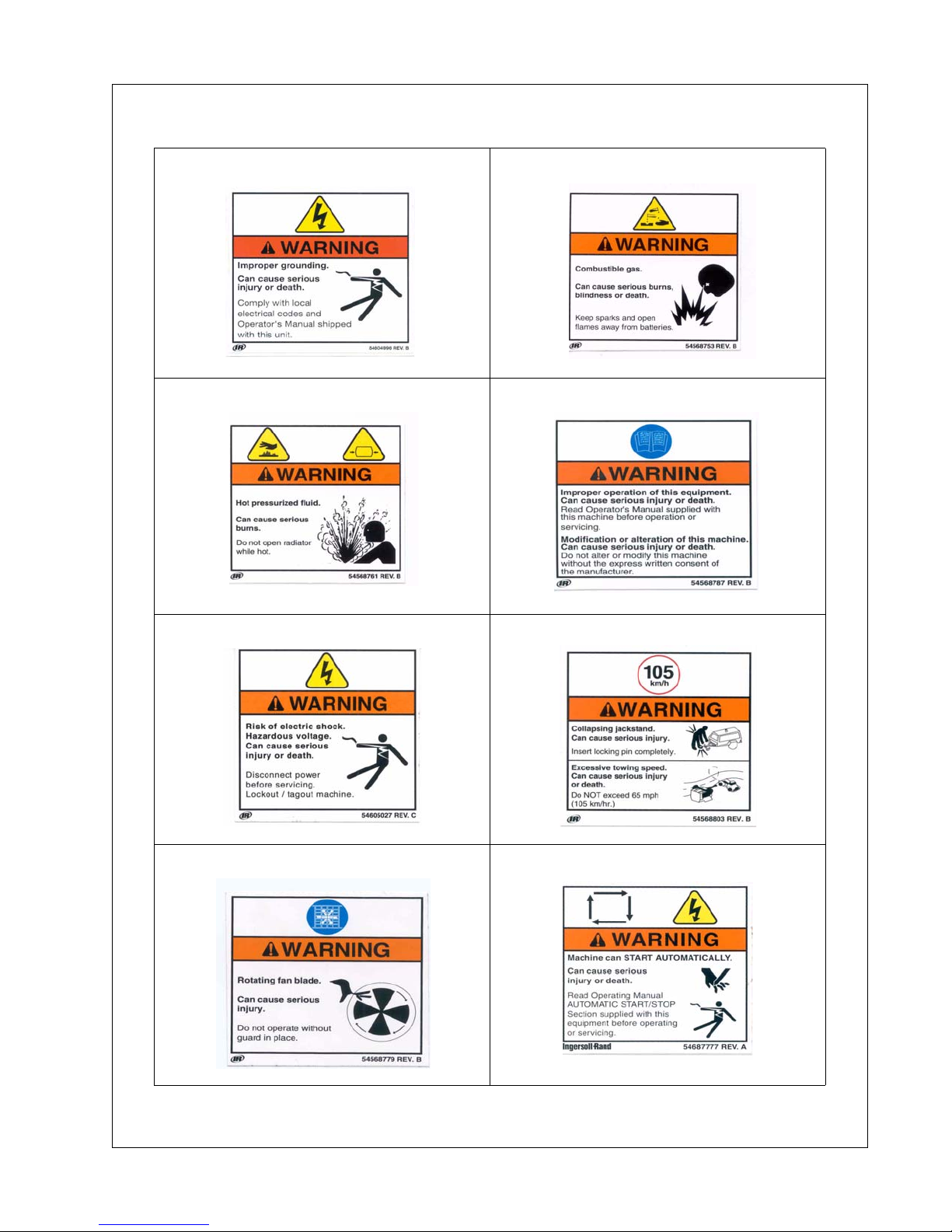
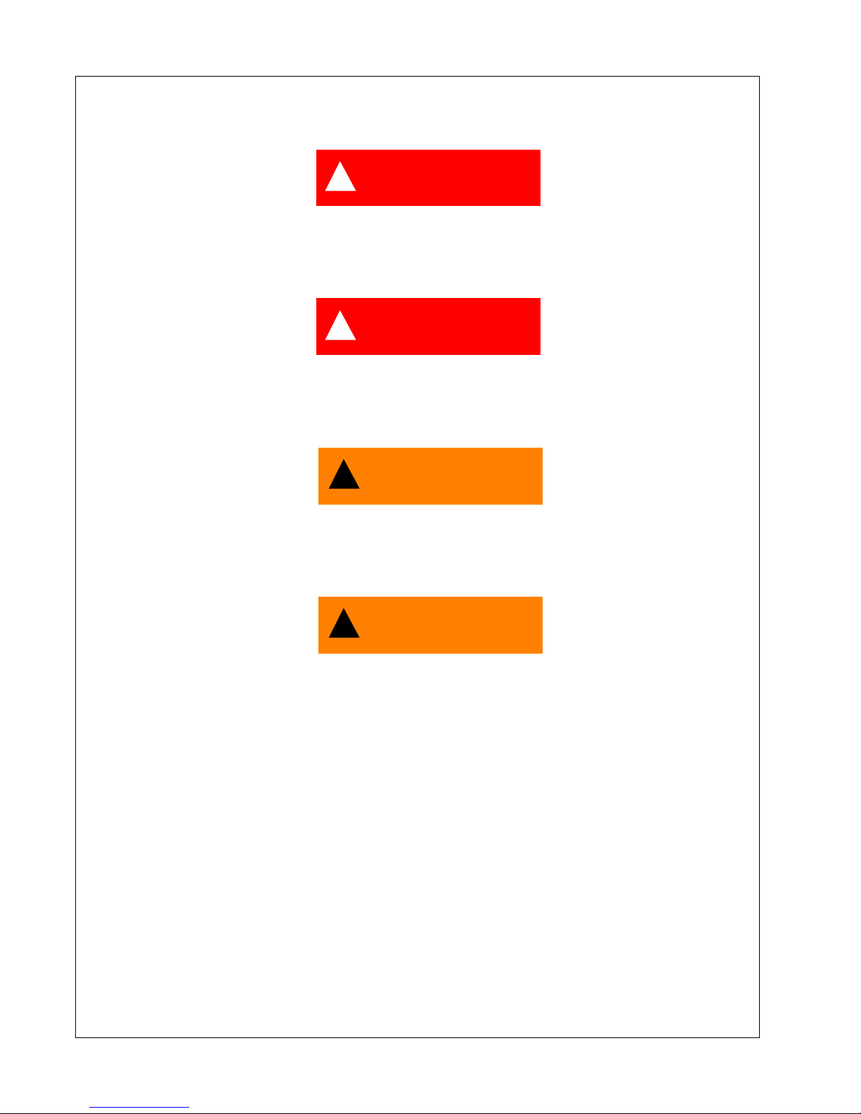
Safety decals are identified by the decal heading:
DANGER, WARNING or CAUTION
Decal part numbers are on the bottom of each decal and are listed
in the parts manual. Help promote product safety! Assure that
decals are present on the machines. Replace decals that are not
legible.
10 22637300
Safety Symbols Operation & Maintenance Manual
22637300 11

Always use genuine replacement parts!
12 22637300

Safety
22637300 13
Operation & Maintenance Manual Safety
Safety
!
DANGER
This machine is not designed for operating life-sustaining equipment. It
is equipped with a safety shutdown system that will cause the machine to
stop operating whenever a shutdown condition is present.
!
DANGER
Never operate the engine of this machine inside a building without
adequate ventilation. Avoid breathing exhaust fumes when working on
on near the machine.
!
WARNING
A battery contains sulfuric acid and can give off gases which are
corrosive and potentially explosive. Avoid contact with skin, eyes, and
clothing. In case of contact, flush area immediately with water.
!
WARNING
Improper operation of this equipment can cause severe injury or death.
Read Operator’s Manual supplied with this machine before operation or
service.
Modification or alteration of this machine CAN result in severe injury or
death. Do not alter or modify this machine without the express written
consent of the manufacturer.
14 22637300
Safety Operation & Maintenance Manual
!
CAUTION
Exercise extreme caution when using booster battery. To jump battery,
connect ends of one booster cable to the positive (+) terminal of each
battery. Connect one end of other cable to the negative (-) terminal of the
bosster battery and other end to a ground connection away from dead
battery (to avoid a spark occurring near any explosive gases that may be
present). After starting unit, always disconnect cables in reverse order.
!
WARNING
Never inspect or service unit without first disconnecting battery cable(s)
to prevent accidental starting.
Wear eye protection while cleaning unit with compressed air, to prevent
debris from injuring eyes.
!
WARNING
HOT PRESSURIZED FLUID - Remove cap slowly to relieve PRESSURE
from HOT radiator. Protect skin and eyes. HOT water or steam and
chemical additives can cause serious personal injury.
22637300 15
Operation & Maintenance Manual Safety
!
WARNING
Flammable Fuels - Do not fill tank when engine is running.
Do not smoke or use an open flame in the vicinity of the generator set or
fuel tank.
Do not permit smoking, open flame, or sparks to occur near the battery,
fuel, cleaning solvents or other flammable substances and explosive
gases.
Do not operate Genset if fuel has been spilled inside or near the unit.
!
WARNING
Electrical Shock -
Do not operate electrical equipment while standing in water, on wet
ground or with wet hands or shoes.
Use extreme caution when working on electrical components. Battery
voltage (12V/24V DC) is present unless the battery cables have been
disconnected. Higher voltage (potentially 480V) is possibly present at all
times.
Always treat electrical circuits as if they were energized.
Disable Start Control before attempting any repair service, disconnect all
leads to electrical power requirements and disconnect battery to prevent
start up.
GROUNDING
!
WARNING
Depending upon your application, it may be MANDATORY to ground this unit to earth or to
NOT ground this unit to earth. Comply with local electrical codes and Operation Manual.
16 22637300

Safety Operation & Maintenance Manual
!
WARNING
The Generator Set can produce high voltages, which can cause severe
injury or death to personnel and damage to equipment. The Generator Set
should have proper internal and external ground when required by the
National Electric Code.
The Generator Set is internally grounded neutral to the frame of the
Generator Set. This internal ground connection is essential for proper
Generator Set performance and personal protection.
External grounding consists of connecting the generator neutral to a
solid earth ground, and is the responsibility of the operator, when
grounding is required by National Electrical Code, Article 250, and other
local codes as applicable. Several methods are employed to externally
ground portable generator sets, depending on the intended use and code
requirements. In all cases, a continuous length of splice-free copper
cable, no smaller than AWG#8, shall be used for the external ground
conductor, when grounding is required.
A qualified, licensed electrical contractor, knowledgeable in local codes,
should be consulted.
The Generator Set has two main applications:
(1) If the Generator Set is supplying electrical power to portable equipment, the vehicle frame
shall NOT be grounded to earth per National Electrical Code, Article 250-34(b). All other
provisions of the Article shall be complied with.
(2) If the Generator Set is connected to a temporary or fixed distribution system (such as a
building), grounding of the vehicle frame is required at the service entrance to the building, per
National Electrical Code, Article 250-20 (b).
If the Generator Set is supplying power to more than one temporary or fixed wiring system, a
separate ground cable must be connected from the generator neutral to each distribution
systems ground as detailed above.
!
WARNING
Failure to properly ground the Generator Set can result in severe injury
or death.
IF USED AS ALTERNATE POWER SUPPLY
Connect only after the main service entrance switch has been DISCONNECTED and
LOCKED OPEN. In addition, circuit overload protection must be provided in accord ance with
National Electrical Codes and local regulations.
22637300 17
Operation & Maintenance Manual Safety
!
WARNING
TOWING -
Do not tow this unit in excess of 65 mph (104 km/hr).
Do not tow this unit with a vehicle whose towing capacity is less than the
gross vehicle weight.
Steps for determining correct load limit -
1. Locate the statement “The weight of cargo should never exceed
xxx kg or xxx lbs” on your vehicle’s placard.
2. This figure equals the available amount of cargo and luggage l oad
capacity.
3. Determine the combined weight of luggage and cargo being loaded
on the vehicle. That weight may not safely exceed the available cargo
and luggage load capacity.
Always make sure the wheels, tires and towbar connectors are in safe
operating condition and tow bar is properly connected before towing.
Chock the wheels of the unit when it is not connected to the tow vehicle.
Do not store or transport material or equipment in or on the unit.
!
WARNING
Drawbar/Hitch Hookup -
Safety chains must be crossed under drawbar and attached to towing
vehicle to prevent drawbar from dropping to ground in event of coupling
failure.
18 22637300
Safety Operation & Maintenance Manual
!
WARNING
If the drawbar is removed from this machine, use new OEM fasteners,
thread locking compound and torque per the tables included in this
manual, when re-installing the drawbar.
!
WARNING
Voltage Selection - Do not turn Voltage Selector Switch while engine is
running. Voltage selection, adjustment and electrical connections shall
be performed only by qualified personnel.
!
CAUTION
Welding -
Prior to any welding, disconnect alternator relays, diagnostic circuit
board, voltage regulator circuit board, meters, circuit breakers and
battery cables. Open all circuit breakers, and remove any external
connections (except grounding rod). Connect the welding ground as
close as possible to the area being welded.
!
WARNING
Electrical Loading -
Never make electrical connections with the unit running.
Before placing the unit in operation, verify the electrical rating of the
Generator Set and do not exceed generator set ratings.
22637300 19

Operation & Maintenance Manual Safety
!
CAUTION
Use extreme care to avoid contacting hot surfaces (engine exhaust
manifold and piping).
HAZARDOUS SUBSTANCE PRECAUTION
Ensure that adequate ventilation of the cooling system and exhaust gases is maintained at all
times.
The following substances are used in the manufacture of this machine and may be hazardous
to health if used incorrectly.
Avoid ingestion, skin contact and breathing fumes for the following substances: Antifreeze,
Engine Lubricating Oil, Preservative Grease, Rust Preventative, Diesel Fuel and Battery
Electrolyte.
The following substances may be produced during the operation of this machine and may be
hazardous to health:
• Avoid build-up of engine exhaust fumes in confined spaces.
• Avoid breathing exhaust fumes.
• Avoid breathing brake lining dust during maintenance.
• Always operate in a well ventilated area.
20 22637300

General Data
22637300 21

Operation & Maintenance Manual General Data
General Data
Unit Model:
UNIT MODEL G10A G25B, G25C G40B, G40C G60
Engine Speed - RPM 1800 1800 1800 1800
ENGINE Diesel Diesel Diesel Diesel
Manufacturer IR IR IR JD
Model 3IRL2N 4IRQ2N 4IRS2N 5030TF270
FLUID CAPACITIES
Engine Crankcase Lubricant .98 1.7 gal 2.64 gal 2.96 gal
Fuel Tank 21 36 gal 47 gal 103 gal
Radiator & Engine Coolant 2.0 4 gal 5 gal 6 gal
Electrical System 12VDC 12VDC 12VDC 12VDC
RUNNING GEAR
Tire Size ST175/80D13 ST205/75D15 ST205/75D15 ST205/75D15
Inflation Pressure (Cold) 50 psi 50 psi 50 psi 50 psi
Towing Speed (Maximum) 65 mph 65 mph 65 mph 65 mph
UNIT MEASUREMENTS/ WEIGHTS (w/running gear)
Overall length (inches) 121 131 143 156
Overall width (inches) 56 60 66 69
Overall height (inches) 43 67 72 85
Track width (inches) 48 50 56 60
Weight (with fuel) 1708 lbs 2588 lbs 3508 lbs 4658 lbs
Weight (less fuel) 1529 lbs 2420 lbs 3078 lbs 3895 lbs
22 22637300

General Data Operation & Maintenance Manual
Unit Model:
UNIT MODEL G70A G80A G90A G125 G145B G185
Engine Speed - RPM 1800 1800 1800 1800 1800 1800
ENGINE Diesel Diesel Diesel Diesel Diesel Diesel
Manufacturer JD JD JD JD JD JD
Model 4045
TF285E
FLUID CAPACITIES
Engine Crankcase Lubricant 3.57 gal 3.57 gal 3.57 gal 3.57 gal 3.57 gal 8.59 gal
Fuel Tank 103 gal 103 gal 190 gal 145 gal 190 gal 255.3 gal
Engine Coolant Only 6 gal 6 gal 3.1 gal 5.3 gal 3.1 gal 3.1 gal
Electrical System 12VDC 12VDC 12VDC 12VDC 12VDC 12VDC
RUNNING GEAR
Tire Size ST205/
75D15
Inflation Pressure (Cold) 50 PSI 50 PSI 50 PSI 50 psi 50 psi 50 psi
Towing Speed (Maximum) 65 mph 65 mph 65 mph 65 mph 65 mph 65 mph
UNIT MEASUREMENTS/ WEIGHTS (w/running gear)
Overall length (inches) 156 156 165 166 166 204
Overall width (inches) 69 69 71 72 72 76
Overall height (inches) 85 85 84 80 84 95
Track width (inches) 60 60 63 64 63 61.7
4045
TF275
ST205/
75D15
4045
HF285
ST205/
75D15
6068
TF275-123
ST205
75D15
4045
HF485
ST205
75D15
6068
HF285
9.50-16.5
LT/E
Weight (with fuel) 5105 lbs 5174 lbs 6466 lbs 5632 lbs 7220 lbs 9166 lbs
Weight (less fuel) 4435 lbs 4478 lbs 5004 lbs 4518 lbs 5758 lbs 7205 lbs
22637300 23

Operation & Maintenance Manual General Data
Unit Model:
UNIT MODEL G240 G290 G450 G570
Engine Speed - RPM 1800 1800 1800 1800
ENGINE Diesel Diesel
Manufacturer JD Cummins Cummins Cummins
Model 6068HF485 QSL9G3 QSX15 QSX15
FLUID CAPACITIES
Engine Crankcase Lubricant
(gal)
Fuel Tank (gal) 255.3 gal 389.5 gal 652 652
Engine Coolant Only (gal) 3.1 gal 2.91 gal 15 15
Electrical System VDC 12VDC 24VDC 24VDC 24VDC
RUNNING GEAR
Tire Size 9.50-16.5 LT/E 9.50-16.5 LT/E 9.50 -16.5 LT/E 9.50 -16.5 LT/E
Inflation Pressure (Cold) psi 50 PSI 50 PSI 75 75
Towing Speed (Maximum) 65 mph 65 mph 65 mph 65 mph
UNIT MEASUREMENTS/ WEIGHTS
Overall length (in/mm) 204 221 261/6626 261/6626
Overall width (in/mm) 76 78 86/2181 86/2181
Overall height (in/mm) 95 111 120/3042 120/3042
Track width (in/mm) 65 68.5 74/ 74/
Weight (with fuel) lbs 9678 lbs 11,957 lbs 18271 18573
Weight (less fuel) lbs 7717 lbs 8989 lbs 13868 14170
8.59 gal 7 gal 24 24
24 22637300

General Data Operation & Maintenance Manual
Consumables Service Parts:
For Models: G10A G25B G40B G60 G 70A G80A G125
Air Cleaner Element
(Engine) primary
Air Cleaner Element
(Engine) secondary optional
Engine Oil Filter
Element
Fuel Water Separator
Element
Engine Fuel Element 85426815 85426823 22712475 22556138 22969257 22206197 22206197
Inline Fuel Filter NA NA NA NA NA NA NA
MAINTENANCE KITS
250 hour Maintenance
Kit (without fluids)
250 hour Maintenance
Kit (& engine fluids)
500 hour Maintenance
Kit (without fluids)
500 hour Maintenance
Kit (& Engine fluids
fluids)
36890135 35393685 35393685 54471834 54471834 54471834 54717145
NA NA NA NA 54471842 NA 54717152
85426849 85426856 22712467 22545867 22206148 22206148 22206148
54525530 54525530 54525530 54525530 22969265 54525530 54468178
44003929 44003945 44000404 44003960 44029098 44003986 44003986
44003648 44003663 44000388 44003705 44029072 44003721 44003747
44003937 44003952 44000412 44003978 44029106 44003994 44004000
44003655 44003671 44000396 44003713 44029080 44003739 44003754
Protec Eng Fluid - 5 gal 54480918 54480918 54480918 54480918 54480918 54480918 54480918
Protec Eng Fluid -1 gal 36875938 36875938 36875938 36875938 36875938 36875938 36875938
22637300 25

Operation & Maintenance Manual General Data
Consumable Service Parts:
For Models: G450 G570
Air Cleaner Element
(Engine) primary
Air Cleaner Element
(Engine) secondary optional
Engine Oil Filter
Element
Fuel Water Separator
Element
Engine Fuel Element 54662036 54662036
MAINTENANCE KITS
250 hour Maintenance
Kit (without fluids)
250 hour Maintenance
Kit (& engine fluids)
500 hour Maintenance
Kit (without fluids)
500 hour Maintenance
Kit (& Engine fluids
fluids)
36864361 36864361
36864379 36864379
54662028 54662028
22201396 22201396
44020279 44020295
44020212 44020238
44020287 44020303
44020220 44020246
Protec Eng Fluid - 5 gal 54480918 54480918
Protec Eng Fluid -1 gal 36875938 36875938
26 22637300

General Data Operation & Maintenance Manual
Expendable Service Parts:
For Models: G90A G145B G185 G240 G290
Air Cleaner Element
(Engine) primary
Air Cleaner Element
(Engine) secondary optional
Engine Oil Filter
Element
Fuel Water Separator
Element
Engine Fuel Element 22206197 22 969257 22969257 22969257 22765325
MAINTENANCE KITS
250 hour Maintenance
Kit (without fluids)
250 hour Maintenance
Kit (& engine fluids)
500 hour Maintenance
Kit (without fluids)
500 hour Maintenance
Kit (& Engine fluids
fluids)
54471834 54717145 54717145 22119168 89288971
NA 54717152 54717152 22119176 89288989
22206148 22206148 22206148 22206148 22177737
54525530 22969265 22969265 22969265 22637904
TBD 44016038 44016038 44016038 44020253
TBD 44016004 44016004 44016004 44020196
TBD 44016046 44016046 44016020 44020261
TBD 44016012 44016012 44016053 44020204
Protec Eng Fluid - 5 gal TBD 54480918 54480918 54480918 54480918
Protec Eng Fluid -1 gal TBD 36875938 36875938 36875938 36875938
22637300 27

28 22637300

Operating Instructions
22637300 29
Operation & Maintenance Manual Operating Instructions
Operating Instructions
Never operate unit without first observing all safety warnings and carefully reading the
operation and maintenance manual shipped from the factory with this machine.
BEFORE TOWING
!
WARNING
Failure to follow these instructions can cause severe injury or death.
!
CAUTION
- Position the tow vehicle to align its hitch with the pintle eye or coupler.
- Engage the parking brake and chock the wheels of the tow vehicle.
- Stand to the side and ensure pin is FULLY inserted (secure) in tube of
jack.
- Crank jack to lower pintle eye coupler onto the hitch and to raise foot off
the ground. Pull pin from tube of jack. Fold jack handle down and forward.
Swing up jack tube and FULLY insert pin in tube.
- Connect machine towing lights to tow vehicle.
- Remove chocks from tow vehicle wheels.
Steps for determining correct load limit -
1. Locate the statement “The weight of cargo should never exceed xxx kg or xxx lbs” on
your vehicle’s placard.
2. This figure equals the available amount of cargo and luggage load capacity.
3. Determine the combined weight of luggage and cargo being loaded on the vehicle.
That weight may not safely exceed the available cargo and luggage load capacity.
30 22637300

Operating Instructions Operation & Maintenance Manual
TOWING
!
WARNING
Failure to follow these instructions can cause severe injury or death.
— Ensure that tires, wheels and running gear are in good condition and secure.
— Ensure that tires are inflated to 50 psi.
— Do not tow this unit in excess of 65 mph (104 km/hr).
— Use a tow vehicle whose towing capacity is greater than the gross weight of this unit.
— Adjust hitch to assure machine is level for towing.
SETTING UP
Place the unit in an open, well ventilated area. Position as level as possible. The design of
these units permits a 15 degree limit on out-of-level operation.
When the unit is to be operated out-of-level, it is important to keep the engine crankcase oil
level near the high level mark (with the unit level).
DISCONNECT
— Set the vehicle parking brake. Chock wheels of unit.
— Disconnect machine towing lights from tow vehicle.
— Standing to the side, remove pin from tube of jack. As jack tube swings down, FULLY
insert pin in the tube.
— Disconnect safety chains. Crank jack to raise eye or coupler from hitch. Tow vehicle
can be moved.
22637300 31

Operation & Maintenance Manual Operating Instructions
BEFORE STARTING
1. Ensure load wiring connections are tight.
2. Check for fluid leaks.
3. Check for fluid level in container base.
4. Check engine oil and coolant level.
5. Check proper grounding circuit. Refer to Safety-Grounding.
6. Check for frayed or loose fan belts, hoses or wiring insulation.
7. Check for leaves, paper, debris in air vents.
8. Check Fuel Level. Add CLEAN diesel fuel.
!
WARNING
Do not remove the cap from a HOT engine radiator. The sudden release
of pressure from a heated cooling system can cause severe injury or
death.
32 22637300

Operating Instructions Operation & Maintenance Manual
STARTING (AUTOSTART MODELS)
!
CAUTION
Use the EMERGENCY STOP button ONLY in the event of an emergency.
NEVER use it for normal shut-down.
Verify the following:
1. All external electrical power loads are turned “OFF”.
2. Main Breaker is “OFF”.
3. Battery Disconnect Switch is “ON”.
4. Ensure that both the VOLTAGE SELECTOR (if equipped) and DIRECT HOOKUP Doors are closed:
5. Reset (pull to unlatch) Emergency Stop Button.
6. Push the Engine “START” Button.
7. Wait for preheating if enabled.
!
CAUTION
Do NOT use engine starting fluids.
!
DANGER
POWER is present upon cranking the engine.
!
CAUTION
Allow starter to cool for one minute between start attempts. If engine
does not start after a few attempts, refer to Trouble Shooting Section.
If engine shuts down, diagnostic lamps will indicate the problem. Correct
the problem before continuing.
22637300 33

Operation & Maintenance Manual Operating Instructions
8. Allow the engine to warm-up for 3 to 5 minutes. If the engine stops
unexpectedly, refer to Trouble Shooting Section.
9. Check the CONTROL Panel for proper voltages. No RED diagnostic lamps
should be glowing. Otherwise, shut down the unit and refer to Trouble
Shooting.
10. With main breaker “ON” power is present and available for use.
11. Close side doors for optimum cooling of the unit while running.
STOPPING (AUTOSTART MODELS)
1. Turn off all external electrical power loads.
2. Turn Main Breaker “OFF”.
3. Allow 5 minute cool down.
4. Push Engine “STOP” Button.
5. Wait at least 15 seconds before restarting.
6. Fill fuel tank at end of working day to prevent condensate.
REMOTE STARTING AND STOPPING
1. Connect the remote start contacts (located in the Generator System direct
hookup compartment) to a customer-supplied contact that closes to initiate a
genset start.
2. Push the Autostart Mode Switch to illuminate the Autostart Mode LED on
control panel.
3. When the customer contact closes, a 10-second alarm will sound prior to each
crank cycle until the engine starts. Preheating will also occur if enabled.
4. The engine will stop when the customer-supplied contact opens, and the
controller will return to the Auto Start Mode.
34 22637300

Operating Instructions Operation & Maintenance Manual
DIAGNOSTICS/AUTO SHUTDOWN (AUTOSTART MODELS)
The operating controls and instruments are arranged on the control panel as shown. A
description of each panel device is as follows:
1. High Engine Temperature - Indicates engine shutdown due to high coolant
temperature or low coolant level.
2. Low Engine Oil Pressure - Indicates engine shutdown due to low engine oil
pressure.
3. Low Fuel Level - Indicates engine shutdown due to low fuel level.
4. High Containment Fluid Level - Indicates high level of fluids in the
containment base.
5. Over Crank - Indicates engine did not start after 3 cranks.
6. Battery Not Charging - Indicates battery voltage is low or not being charged.
7. Engine Speed - Indicates engine overspeed.
8. Engine Operating - Indicates engine is cranking or operating.
9. Preheat - Indicates preheating is on.
10. Engine Communication - Indicates the controller has commu nication with the
engine ECU. (N/A for G20-G40).
11. Engine Fault - Indicates that engine service is required. (N/A for G25-G40).
ENGINE CONTROLS and INSTRUMENTS (AUTOSTART MODELS)
12. Engine Start Switch
13. Engine Stop/Reset Switch - Stops engine and resets diagnostics. Also,
awakens controller from sleep mode. Wait 15 seconds for reset to complete
before attempting start.
14. Autostart Mode Switch - Puts engine in Autostart Mode.
15. Autostart Mode - Indicates genset is in Autostart Mode. Note: the controller
will enter low power sleep mode after a short time and all other LED’s will go off.
16. Emergency Stop Switch - Disables running, cranking, and trips main breaker.
17. Alarm Horn - Sounds prior to a start when in Auto Start Mode (not visible)
18. Diagnostic Trouble Code (DTC) Display - Displays engine shutdown and
warning codes, and text messages on electronic ECU engines.
19. Autostart/Stop Controller
20. Hourmeter - Indicates engine run hours.
21. Battery Volts
22. Fuel Level
22637300 35

Operation & Maintenance Manual Operating Instructions
(19)
(20)
(21)
(22)
(18)
36 22637300

Operating Instructions Operation & Maintenance Manual
CUSTOMER - DIAGNOSTIC GAUGE OPERATION
AUTO Mode Any active engine SPN codes are automatically deployed for 3
seconds each.
Auto mode is default on power up.
Press “SPN” for 3 seconds to return to AUTO mode from
MANUAL mode.
“MEM” indicator is on if engine ECU contains stored codes - Go
to “MAN” mode to see codes.
MANUAL Mode Used to see both active and stored engine codes, and to see
additional SPN data (FMI, OC, SRC).
Press “i” or “SPN” for MANUAL mode if in AUTO.
Press “SPN” to advance to the next SPN code.
Press “i” to get additional data on any displayed SPN.
If the “MEM” indicator is lit, then the displayed SPN is a stored
(not active) code.
Unit will return to AUTO mode in 30 seconds.
22637300 37

Operation & Maintenance Manual Operating Instructions
STARTING (KEY START MODELS)
!
CAUTION
Use the EMERGENCY STOP button ONLY in the event of an emergency.
NEVER use it for normal shut-down.
Verify the following:
1. All external electrical power requirements are turned “OFF”.
2. Main Breaker is “OFF”.
3. Battery Disconnect Switch “ON”
4. Ensure both the VOLTAGE SELECTOR (if equipped) and DIRECT HOOK-UP
terminal doors are closed.
5. Reset (pull to unlatch) Emergency Stop Button.
6. Turn the ENGINE START SWITCH to “PREHEAT” for maximum of 10 seconds
for cold weather starts.
7. Turn ENGINE START switch to “START”. Release after engine starts.
!
CAUTION
Do NOT use engine starting fluids.
!
DANGER
POWER is present upon cranking the engine.
38 22637300

Operating Instructions Operation & Maintenance Manual
!
CAUTION
Allow starter to cool for one minute between start attempts. If engine
does not start after a few attempts, refer to Trouble Shooting Section.
If engine shuts down when ENGINE START switch in in the “ON” position,
diagnostic lamps will indicate the problem. Correct the problem before
continuing.
22637300 39

Operation & Maintenance Manual Operating Instructions
1.
1. Allow the engine to warm-up for 3 to 5 minutes. If the engine stops
unexpectedly, refer to Trouble Shooting Section.
2. Check the CONTROL Panel for proper voltages. No RED diagnostic lamps
should be glowing. Otherwise, shut down the unit and refer to Trouble Shooting
Section.
3. With main breaker “ON” power is present and available for use.
4. Close side doors for optimum cooling of the unit while running.
STOPPING (KEYSTART MODELS)
1. Turn off all external electrical power loads.
2. Turn Main Breaker “OFF”.
3. Allow 5 minute cool down.
4. Turn the Engine Start Switch to “OFF”.
5. Fill fuel tank at end of working day to prevent condensate.
DIAGNOSTICS and AUTO SHUTDOWN (KEYSTART MODELS)
On some models, the operating controls and instruments are arranged on the control panel as
shown. A description of each panel device is as follows:
1. High Engine Temperature - Indicates engine shutdown due to high engine
coolant temperature.
2. Low Engine Oil Pressure - Indicates engine shutdown due to low engine oil
pressure.
3. Low Fuel Level - Indicates engine shutdown due to low fuel level.
4. High Containment Fluid Level - Indicates high fluid level in the containment
base.
40 22637300

Operating Instructions Operation & Maintenance Manual
ENGINE CONTROLS and INSTRUMENTS (Keystart Models)
5. Engine Start Switch Positions - PREHEAT, OFF, RUN, START.
6. Emergency Stop- Disables running, cranking, and trips main breaker.
7. Hourmeter - Records operating time.
8. Fuel Level - Indicates fuel level in fuel tank.
9. Voltmeter - Indicates battery charging voltage.
(8)
(7)
22637300 41

Operation & Maintenance Manual Operating Instructions
GENERATOR SYSTEM
METERS
1. AC Volts - Indicates the generator output voltage corresponding to VOLTAGE
OUTPUT MONITOR switch position.
2. AC Amperes - Indicates the generator load in amperes corresponding to
AMPERAGE OUTPUT MONITOR switch position.
3. Hertz - Indicates frequency of generator output.
4. Panel Lamp - Illumination Only.
MONITOR SWITCHES
5. Voltage Output - Selects the line to line (phase) or line to neutral (phase to
neutral) generator voltage to be displayed on the AC Voltmeter.
6. Amperage Output - Selects the line (phase) amperage to be displayed on the
AC Ammeter.
7. Voltage Adjust Rheostat (VAR) - Turn to adjust generator output voltage.
8. Trip Reset Button - Push to reset the overcurrent relay that trips the main
breaker.
42 22637300

Operating Instructions Operation & Maintenance Manual
CIRCUIT BREAKERS - Flip to Reset (if equipped)
9. 20 AMP/120 Volt - (two)
10. 50 AMP/120V/240 Volt (one, two or three)
RECEPTACLES (if equipped)
11. 125 Volt 1 Phase - GFI, straight blade, duplex.
12. 125/250 VOLT 1 Phase - Special “Tempower” Twist Lock, CS-6369.
PROTECTION/REGULATION
13. 3 Phase Direct Hookup Connections - LO, L1, L2, L3,
14. Fuse Holders- Fuses for voltage output selector switch and meter. (not shown)
15. Overcurrent Protection Relay - (not shown) but is located behind reset
button,8.
16. Main Circuit Breaker
17. Alarm Horn - (not shown) but is located on back of control box.
22637300 43

VOLTAGE SELECTION/ADJUSTMENTS G25 thru G185
!
DANGER
This set up procedure shall be performed only by knowledgeable qualifed
persons. Ensure all external electrical connections are disconnected.
Use extreme CAUTION when working on electrical components. Battery
voltage (12V or 24V) is present unless the battery cables are
disconnected. Higher voltage (potentially 480V) is present at all times
when the engine is running.
This Generator Set may be equipped with both panel convenience
receptacles (120 and 240 volts, 1-phase) and direct wiring hook-ups. Any
of the voltages listed below are obtainable by connection to the direct
hook-up terminal block.
NOTICE
Do not hook-up electrical loads until following adjustments have been
completed, otherwise damage to the equipment may result.
SET-UP PROCEDURE
Before starting and making electrical connections:
1. Open the VOLTAGE SELECTOR switch door.
2. Position the VOLTAGE SELECTOR switch to the desired voltage.
3. Close and latch the VOLTAGE SELECTOR switch door.
4. Start the unit per the Operating Section instructions.
!
DANGER
Electric power is present at all times when the Generator Set Engine is
running.
5. Fine tuning of the VOLTAGE ADJUSTMENTS are as follows:
44 22637300

Operating Instructions Operation & Maintenance Manual
SWITCH POSITION - 120/208V 3 Phase
1. Turn Voltage Output Monitor to L1-L2 position.
2. Turn Voltage Adjust Rheostat (VAR) Shaft to read 208V on AC Voltmeter.
3. Turn Voltage Output Monitor to L
4. Turn Voltage Output Monitor to L
5. Power is available on all panel receptacles.
6. Turn Voltage Output Monitor to L
7. Shutdown unit.
8. Make 120/208V connections at the direct hook-up terminal blocks.
9. At start-up, 120/208V will be present.
position and verify 208V ± 5%.
2-L3
position and verify 208V ± 5%.
3-L1
position and verify 120V ± 5%.
1-L0
SWITCH POSITION - 277/480V 3 Phase
1. Turn Voltage Output Monitor to L1-L0 position.
2. Turn Voltage Adjust Rheostat (VAR) Shaft to read 277V on AC Voltmeter.
3. Turn Voltage Output Monitor to L
4. Turn Voltage Output Monitor to L
5. One of the 120V 15A or 20A panel receptacles now has power. The right
duplex receptacle is “not active in 480V mode.”
position and verify 277V ± 5%.
2-L0
position and verify 277V ± 5%.
3-L0
6. Turn Voltage Output Monitor to L
7. Shutdown unit.
8. Make 277/480V connections at the direct hook-up terminal blocks.
9. At start-up, 277/480V will be available at the direct hook-up terminal blocks.
position and verify 480V ± 5%.
1-L2
NOTICE
Applying single-phase loads or receptacle loads when in 3-phase switch
positions can cause unbalanced loading of windings in excess of the
maximum recommended, which may shorten alternator life.
22637300 45

Operation & Maintenance Manual Operating Instructions
SWITCH POSITION - 120/240 1Phase
1. Turn Voltage Output Monitor to L1-L2 position.
2. Turn Voltage Adjust Shaft to read 240V on AC Voltmeter.
!
CAUTION
Do not use L3-L0 due to the likelihood of equipment damage.
3. Turn Voltage Output Monitor to L
4. Turn Voltage Output Monitor to L
5. Power is available on all panel receptacles.
6. Shut down unit.
7. Make 120/240V connections at either the panel receptacles or the direct hookup terminal blocks.
8. At start-up, 120/240V will be present.
It may be necessary to check the voltage at the end of long drop cord and increase the voltage
to compensate for losses.
Voltages required other than those specified above may be adjustable within the following
ranges. Follow the National Electrical Code and Local Codes. DO NOT exceed recommended
voltages output to equipment.
Selector Switch Position Line-Neutral Line - Line
position and verify 120V ± 5%.
1-L0
position and verify 120V ± 5%.
2-L0
Voltage Adjustment Range
L
1-L0
L1-L
2
120/208 110V-140V 190V-240V
277/480 220V-290V 380V-500V
120/240 100V-120V 190V-240V
46 22637300

Operating Instructions Operation & Maintenance Manual
VOLTAGE SELECTION/ADJUSTMENTS G240 thru G570
!
DANGER
This set up procedure shall be performed only by knowledgeable qualifed
persons. Ensure all external electrical connections are disconnected.
Use extreme CAUTION when working on electrical components. Battery
voltage (12V or 24V) is present unless the battery cables are
disconnected. Higher voltage (potentially 480V) is present at all times
when the engine is running.
This Generator Set is equipped with direct wiring hook-ups. Any of the
voltages listed below are obtainable by connection to the direct hook-up
terminal block.
NOTICE
Do not hook-up electrical loads until following adjustments have been
completed, otherwise damage to the equipment may result.
SET-UP PROCEDURE
Before starting and making electrical connections:
1. Remove the top cover on junction box (located on the AC Alternator).
2. Remove all nuts and washers from all the studs in the junction box and position
the copper bars on the studs as seen in figure A for 120/208V AC or figure B
for 277/480V AC.
3. Once bars are in position for the voltage you will need, reinstall nuts and
washers and tighten to 50 ft lbs. and replace cover. Note:
properly installed for either 480V or 208V, it automatically activates the control circuit
Automatic Reconnect Switch located under the busbar.
4. Start the unit per the Operating Section instructions.
When the busbar is
22637300 47

Operation & Maintenance Manual Operating Instructions
Figure A: Connection Chart
Desired Output Voltage 208/240 Output
Busbar Links
T1-T7, T2-T8, T3-T9, T4 to T10, T5 to T11, T6 to T12
T10 to T11 to T12
Figure B:
!
DANGER
Electric power is present at all times when the Generator Set Engine is
running.
5. Fine tuning of the VOLTAGE ADJUSTMENTS are as follows:
48 22637300

Operating Instructions Operation & Maintenance Manual
120/208V 3 Phase
1. Turn Voltage Output Monitor to L1-L2 position.
2. Turn Voltage Adjust Rheostat (VAR) Shaft to read 208V on AC Voltmeter.
3. Turn Voltage Output Monitor to L
4. Turn Voltage Output Monitor to L
5. Turn Voltage Output Monitor to L
position and verify 208V ± 5%.
2-L3
position and verify 208V ± 5%.
3-L1
position and verify 120V ± 5%.
1-L0
6. Shutdown unit.
7. Make 120/208V connections at the direct hook-up terminal blocks.
8. At start-up, 120/208V will be present.
277/480V 3 Phase
1. Turn Voltage Output Monitor to L1-L0 position.
2. Turn Voltage Adjust Rheostat (VAR) Shaft to read 277V on AC Voltmeter.
3. Turn Voltage Output Monitor to L
4. Turn Voltage Output Monitor to L
5. Turn Voltage Output Monitor to L
6. Shutdown unit.
7. Make 277/480V connections at the direct hook-up terminal blocks.
position and verify 277V ± 5%.
2-L0
position and verify 277V ± 5%.
3-L0
position and verify 480V ± 5%.
1-L2
8. At start-up, 277/480V will be available at the direct hook-up terminal blocks.
22637300 49

Operation & Maintenance Manual Operating Instructions
BASIC DIGITAL CONTROLS OPERATION
Overview
Ingersoll Rand's Digital Controller is a comprehensive generator set controlle r that is used as
the primary interface between the operator and the generator set. It provides a high degree of
engine and generator protection. Multiple real-time parameters can also be viewed. The
parameters include, but are not limited to kW, KVA, kVAr, power factor, oil pressure, coolant
temperature, engine speed, and diagnostic history.
50 22637300

Operating Instructions Operation & Maintenance Manual
IDENTIFYING KEYPAD BUTTONS AND INDICATORS
OPERATION BUTTONS
22637300 51

Operation & Maintenance Manual Operating Instructions
Status LED’s
Shutdown - Indicates the generator set has shutdown due to a fault.
Not in Auto - Indicates that the generator set operation mode is not in the automatic position.
Running - Indicates that the generator set is running.
Warning - Indicates that the generator set is operating in a condition outside its normal
operational parameters.
Ready/Auto - Indicates the generator set is ready and is in automatic mode.
Supplying Load - Indicates that the generator set is under load.
52 22637300

Operating Instructions Operation & Maintenance Manual
VIEWING REAL-TIME DATA - ACCESSING THE SCREENS
22637300 53

Operation & Maintenance Manual Operating Instructions
54 22637300

Operating Instructions Operation & Maintenance Manual
22637300 55

Operation & Maintenance Manual Operating Instructions
CHECKING SOFTWARE VERSION/LAMP TEST
To check the software version and to test the operation of the LED's on the control panel,
simultaneously press
ADJUSTING THE CONTRAST ON THE LCD
To adjust the contrast on the LCD display, simultaneously press
56 22637300

Operating Instructions Operation & Maintenance Manual
PARAMETER ADJUSTMENTS VIA KEYPAD
22637300 57

Operation & Maintenance Manual Operating Instructions
SETPOINTS DESCRIPTIONS
BASIC SETTINGS
Gen-Set Name
User defined name, used for the CONTROLLER identification at remote phone or mobile
connection. The Gen-set name is max 14 characters long and has to be entered using Lite
Edit software.
Nomin Power (3ph)
Nominal power of the generator in three phase HI-WYE series connection.
Nomin Current
Nominal current of the generator in three phase LOW-WYE parallel connection.
CT Ratio
The generator set current transformer ratio.
PT Ratio
The generator set potential transformers ratio. PT's are not needed on 480 Volt systems and
below.
Nominal Voltage 1
Line to neutral voltage in LOW-WYE, Parallel connection.
Nominal Voltage 2
Line to neutral voltage in HI-WYE, series connection.
Gear Teeth
Number of teeth on the engine gear for the pick-up. Set to zero, if no pick-up is used. Engine
speed is counted from the generator frequency. Electronic engines get the speed signal from
the engine controller.
Alternator Frequency
Frequency of the battery alternator when the controller stops cranking.
Nominal RPM
The nominal engine speed of the generator set.
Mode [OFF, MAN, AUT]
This is the equivalent of controller "Mode" buttons.
Fault Reset Go to Manual
Enables or Disables return to MAN mode when reset is pushed.
Display Backlight Timeout
The time limit in minutes for the backlight to go off.
58 22637300

Operating Instructions Operation & Maintenance Manual
IL Power OFF
The time limit in minutes for the controller to go to Sleep Mode. The control power is restored
by pushing the Control Power Button for 5 seconds.
Controller ADDR
The setting of the controller address.
RS232 Mode
The communication protocol selection.
Standard = Lite Edit
Modbus = Modbus Protocol
Cummins MB = Cummins Modbus Protocol
ENGINE PARAMETERS
Start RPM
"Firing" speed when controller stops cranking (starter goes OFF).
Starting POil
When reached, controller stops cranking (starter goes OFF). There are three conditions for
stop cranking: Starting RPM, Starting POil and D+ (when enabled). The starter goes off when
any of these conditions are valid.
PreHeat Time
The time delay for preheating after the unit gets the start command. The unit begins to start
after preheating. Select No Preheat with a setting = O. Factory default setting = 10 seconds.
MaxCrank time
Maximum time limit of cranking.
Crank Fail Pause
Pause time between crank attempts.
Crank Attempts
Maximum number of crank attempts.
Idle Time
Idle time delay starts when RPM exceeds Start RPM. Start fail is detected when during idle
state RPM decrease below 2.
22637300 59

Operation & Maintenance Manual Operating Instructions
Min Stability Time
Generator nominal voltage starts being detected after starter is switched off, idle time elapses,
and this time has elapsed.
Max Stability Time
If generator nominal voltage is not stable within the time after starter is OFF and idle time
elapes, then the genset will shutdown. Stability means that voltage and frequency are within
warning setting limits.
Cooling Speed
This function is not used. Reserved for future applications. Factory default setting = NOMINAL.
Cooling Time
Runtime of the unloaded generator set to cool the engine before stop.
After Cool Time
This function is not used. Factory default setting = 0.
Stop Time
When genset stop sequence is initiated, fuel solenoid output cannot activate during this time.
Fuel Solenoid
Determines behavior of the Binary output FUEL SOLENOID.
DIESEL: Output closes together with Binary output STARTER.
The output opens if Emergency stop comes or Cooled generator set is stopped or in pause
between repeated starts.
GAS: Output closes together with Binary output IGNITION if RPM is over the 30 RPM (Fix
value). Output opens after stop command or in pause between repeated start.
Fuel Pull Coil
Time duration that output Fuel Pull Coil is active. This output is used for momentary activation
of a fuel solenoid pull coil.
60 22637300

Operating Instructions Operation & Maintenance Manual
D+ Function
ENABLED: The D+ terminal is used for both functions - "running engine" detection and charge
fail detection.
CHRGFAIL: The D+ terminal is used for charge fail detection only.
DISABLED: The D+ terminal is not used, but still provides flash voltage to battery alternator.
ECU Freq Select
This function is not used. Factory Setting = DEFAULT.
ECU Speed Adjust
This function is not used. Factory Default Setting = O
ENGINE PROTECTION
Eng prot del [s]
During the start of the generator set, some engine protections have to be blocked (e.g. Oil
Pressure). The protections are unblocked after the protection del time. The time starts after
reaching START RPM.
Alarm Horn
Three selections possible:
NONE = Horn only sounds for 10 seconds prior to a start in Auto Mode.
SHUTDOWN = Horn sounds for any shutdown and also for an Autostart.
SD+ WARNING = Horn sounds for any alarm or shutdown and also for an Autostart.
Overspeed
Threshold for overspeed protection.
Wrn Oil Press
Warning threshold for low oil pressure.
Sd Oil Press
Shutdown threshold level low oil pressure.
Oil Press Del
Delay for oil pressure warning/shutdown.
Sd Engine Temp
Shutdown threshold level for high engine coolant temperature.
Wrn Engine Temp
Warning threshold level for high engine coolant temperature.
Wrn Eng Temp Low
Warning threshold level for low engine coolant temperature.
22637300 61

Operation & Maintenance Manual Operating Instructions
Engine Temp Del
Delay for high/low engine coolant temperatures.
Wrn Fuel Level
Warning threshold level for low fuel level.
Sd Fuel Level
Shutdown threshold level for low fuel level.
Fuel Level Del
Delay for low fuel level.
Batt Overvolt
Warning threshold for high battery voltage.
Batt Undervolt
Warning threshold for low battery voltage.
Battvolt del
Delay for low battery voltage alarm.
NextServTime [h]
Counts down when engine running. If reaches zero, an alarm appears.
ALTERNATOR PROTECTION
Overload
Threshold for generator overload (in % of nominal power)
Overload Wrn
Threshold for generator overload warning (in % of nominal power)
Overload del
Delay for generator overload alarm.
Ishort
Shutdown occurs when lshort circuit limit is reached.
Ishort del
Delay for lshort Alarm.
2Inom del
IDMT is "very inverse" generator over current protection. 2Inom del is Reaction time of IDMT
protection for 200% overcurrent Igen = 2* Nominal current.
Curr unbal del
Delay for generator current asymmetry.
62 22637300

Operating Instructions Operation & Maintenance Manual
Gen >V Sd
Shutdown level for generator over voltage. All three phases are checked. Maximum out of
three is used.
Gen >V Wrn
Warning level for generator over voltage. All three phases are checked. Maximum out of three
is used.
Gen <V Sd
Shutdown level for generator under voltage. All three phases are checked. Minimum out of
three is used.
Gen <V Wrn
Warning level for generator under voltage. All three phases are checked. Minimum o ut of three
is used.
Gen V del
Delay for generator under voltage and over voltage alarm.
Volt unbal
Threshold for generator voltage unbalance alarm.
Volt unbal del
Delay for generator voltage unbalance alarm.
Gen >f SD
Shutdown level for generator over frequency.
Gen>f Wrn
Warning level for generator over frequency.
Gen <f Wrn
Warning level for generator under frequency.
Gen <f SD
Shutdown level for generator under frequency.
Gen f del
Delay for generator under frequency and over frequency alarm.
22637300 63

Operation & Maintenance Manual Operating Instructions
DATE/TIME
Time Stamp Per
Fixed time interval when history of all parameters is recorded. Factory Default Setting = 0.
Summer Time Mod
Automatic time adjustment for daylight savings time.
Time
Time of day setting.
Date
Date setting
Timer 1 Repeat
Selection of day/days when exercise Timer 1 will run.
Timer 1 on Time
Selection of time of day when Timer 1 will start the genset.
Timer 1 Duration
Selection of length of run time.
Timer 2 Repeat
Selection of day/days when exercise Timer 2 will run.
Timer 2 on Time
Selection of time of day when Timer 2 will start the genset.
Timer 2 Duration
Selection of length of run time.
64 22637300

Maintenance
22637300 65

Operation & Maintenance Manual Maintenance
Maintenance
!
CAUTION
Any unauthorized modification or failure to maintain this equipment may
make it unsafe and out of factory warranty.
!
WARNING
Before attempting any repair service, disconnect engine battery cables
and all leads to electrical power requirements. Failure to do so can result
in severe personal injury, death or damage to the equipment.
General
In addition to periodic inspections, many of the components in this unit requires periodic
servicing to provide maximum output and performance. Servicing may consist of pre-operation
and post-operation procedures to be performed by the operating or maintenance personnel.
The primary function of preventive maintenance is to prevent failure and consequently, the
need for repair. Preventive maintenance is the easiest and the least expensive type of
maintenance. Maintaining your unit and keeping it clean at all times will facilitate servicing.
Scheduled Maintenance
The maintenance schedule is based on normal operation of the unit. In the event unusual
environmental operating conditions exist, the schedule should be adjusted accordingly.
Wiring Routing Clamps
Daily check for loose wire routing clamps. Clamps must be secure and properly mounted. Also
check wiring for wear, deterioration and vibration abrasion.
Electrical Terminals
Check daily for evidence of arcing around electrical terminals.
Grounding Circuit
Daily check that the grounding circuit is in accordance with the National Electrical Code Article
250-122 and the local code requirements. As a minimum, the copper wire size should be
American Wire Gauge 8 (AWG#8) from the grounding terminal, frame, generator and engine
block.
66 22637300

Maintenance Operation & Maintenance Manual
Hoses
Each month it is recommended that the intake hoses from the air cleaner and all flexible hoses
used for water and fuel be inspected for the following:
1. All rubber hose joints and the screw type hose clamps must be tight and the
hoses showing no signs of wear, abrasion or deterioration.
2. All flexible hoses must be free of wear, deterioration and vibration abrasion.
Routing clamps must be secure and properly mounted.
Wiring Insulation
Daily check for loose, or frayed wiring insulation or sleeving.
Fuel/Water Separator
Daily check for water in the fuel filter/water separator unit. Some engines have a translucent
bowl for visual indication, and others have a drain valve below the primary element.
Every six months or 500 hours, or less if fuel is of poor quality or contaminated, replace the
bowl elements(s).
Air Vents
Daily clean the air vents of any obstruction or debris.
Air Cleaner
Proper maintenance of the air cleaner provides maximum protection against airborne dust.
Squeeze the rubber valve (precleaner dirt dump periodically to ensure that it is not clogged).
To service the air cleaners, proceed as follows:
1. Remove filter element.
2. Inspect air cleaner housing for any condition that might cause a leak and
correct as necessary.
3. Wipe inside of air cleaner housing with a clean, damp cloth to remove any dirt
accumulation. This will permit better seal for gasket on filter element.
4. Install element.
The air cleaner assembly (housing) should be inspected every 3 months or 500 hours for any
leakage paths.
Note: Make sure the inlet is free from obstruction.
Make sure the air cleaner mounting bolts and clamps are tight and the air cleaner is mounted
securely. Check the air cleaner housing for dents or damage to the cleaner, which could le ad
to a leak.
22637300 67

Operation & Maintenance Manual Maintenance
Fasteners
(See following inch torque chart, metric torque chart and wheel torque chart). All fasteners
should be torqued in accordance to size and grade.
Torque Chart
68 22637300

Maintenance Operation & Maintenance Manual
Wheel Torque Chart
M12 Bolts Torque (Ft-Lbs)
13” wheel 60-70
1/2" lug nuts
13” wheel 80-90
15” wheel 105-115
16” wheel 105-115
16.5 wheel 105-115
5/8" lug nuts
16” wheel 190-210
17.5 wheel 190-210
Tires
Weekly check the condition of the tires, and gauge the air pressure. Tires that have cuts or
cracks or little tread should be repaired or replaced.
Engine Radiator
Check the coolant level in the radiator. The coolant must cover the tubes in the top tank
(approximately 1 inch high on a clean measuring rod, stuck down filler neck).
!
WARNING
Remove cap slowly to relieve pressure from HOT radiator. Protect skin
and eyes. Hot water or steam and chemical additives can cause serious
personal injury.
The engine coolant system is normally filled with a 50/50 mixture of water and ethylene glycol.
This permanent type anti-freeze contains rust inhibitors and provides protection to -35°F (37°C). The use of such a mixture is recommended for both summer and winter operation.
When using water alone, be sure to add a reputable bra nd of rust inhibitor to prevent internal
corrosion.
It is recommended to test the freezing protection of the coolant every six months or prior to
freezing temperatures. Replenish with a fresh mixture every twelve months.
Each month, inspect the radiator exterior for obstructions, dirt and debris. If present, blow
water or compressed air containing a non-flammable solvent between the fins in a direction
opposite the normal air flow. Should the radiator be clogged internally, reverse flushing, using
a commercial product and the supplier’s recommended procedure, may correct the problem.
22637300 69

Operation & Maintenance Manual Maintenance
Diagnostic Lamps
On Keystart models, each month the diagnostic lamps should be tested. With unit shutdown
and emergency stop pushed, turn the Engine Start Switch to “START”, or pull the ESTOP to
apply power to the controller. All diagnostic lamps should glow; If not, refer to troubleshooting.
Diagnostic Trouble Code (DTC) Display
On models with Electronic (ECU) engines, each month, the DTC display should be tested.
When unit is started, the DTC Display should show dashes (----) or a trouble code if there is a
fault condition.
Emergency Stop Switch
Each month, check the operation of the emergency stop switch. Running with no electrical
loads and the main breaker “ON”, press the EMERGENCY STOP SWITCH. The unit should
shutdown immediately and the main breaker should trip with cranking disabled. Emergency
Stop Switch must be reset (pull to unlatch) for operation.
Voltage Selector Door Interlock Switch
Every three months or 250 operating hours, the interlock switch should be checked. Runnin g
with no electric load, open the VOLTAGE SELECTOR door. This will shutdown the engine and
trip the main breaker. To reset, close the door.
Engine Protection Shutdown System
The operation of the engine protection shutdown system should be checked, whenever it
appears not to be operating properly. The three devices involved in this protective shutdown
system are the engine coolant high temperature switch/sensor, the engine oil pressure switch/
sensor and the low fuel switch.
The engine oil pressure switch/sensor prevents the engine from operating with low oil
pressure. Once a month, remove a wire from the engine oil pressure switch/sensor to check
the shutdown system for proper operation. Do the same for the wire on the engin e temperature
switch/sensor.
High Containment Fluid Alarm System
The operation of the high containment fluid alarm system should be checked every 3 months
or whenever it appears not to be operating properly.
The level switch is located at the lower end of a pipe at the bottom of the containment tank.
Test the switch by unfastening the u-bolts holding the pipe, and then inverting the pipe to allow
the switch float to fall.
The “High Containment Level” LED should illuminate. Replace any defective switch.
Drain the containment area using the drain plug at either end of the containment basin.
70 22637300

Maintenance Operation & Maintenance Manual
ADJUSTMENT INSTRUCTIONS and TESTING PROCEDURES
ACCESSING COMPARTMENT
1. Disconnect all electrical loads to the unit.
!
DANGER
High Voltage is present in alternator and control compartments when
engine is running. Battery voltage is present whenever battery is
connected.
2. With engine stopped, remove the plate on the left side or front of the alternator
junction box.
VOLTAGE REGULATOR ADJUSTMENT
Refer to ACCESSING COMPARTMENT Section and Figure 8-1 for locations.
1. With all electric loads disconnected, engine stopped and main breaker turned
on, turn VOLTAGE SELECTOR Switch to 277/480V position, and close and
latch the VSS door.
2. Adjust “Voltage” POT(P2) on regulator to full counterclockwise position.
3. Adjust “Voltage” POT on control panel
4. Start unit.
5. Verify generator frequency to 62-63 Hz at no load on G10 - G40, 60-60.5 Hz on
G60 - G570.
6. Set the VOLTAGE OUTPUT MONITOR switch on the control panel to L
position.
7. Adjust “VOLTAGE” POT(P2) on the regulator to read 500V on AC voltmeter.
8. Adjust “Stability” POT(P3) counter clockwise until the AC volts within ± 1 volt.
Then turn the adjusting “Stability” POT (P3) some 5-10 degrees clockwise.
9. Adjust “Voltage” POT on control panel to read 480V on AC voltmeter.
10. Stop Generator Set.
to full clockwise position.
1-L2
11. Check the range in each VOLTAGE SELECTOR switch position (120/208, 120/
240 and 277/480).
22637300 71

Operation & Maintenance Manual Maintenance
OVERCURRENT RELAY ADJUSTMENT (Set Dial on the OCR Relay)
Overcurrent Relay Adjustment
KVa
25 2.1 34
40 2.3 47
60 1.9 77
70 1.9 96
80 2.2 109
90 2.4 124
125 2.1 165
145 2.4 190
185 2.0 242
240 2.0 314
290 1.9 384
315 2.1 415
450 2.0 603
Setting ±
0.1
AMPS
570 2.4 754
72 22637300

Maintenance Operation & Maintenance Manual
POWER BYPASS SWITCH FOR ENGINE ECU SERVICE
Push the Power Bypass Switch to temporarily apply power to the engine ECU during engine
computer diagnostics on a stopped engine. The switch is located on the side of the engine next
to the Can Bus diagnostic connector.
22637300 73

PACKAGE PREVENTIVE MAINTENANCE SCHEDULE
Daily Weekly Mon.
Evidence of Arcing around electrical terminals C
Loose Wire Routing Clamps C
Engine Oil and Coolant Level C
Proper Grounding Circuit C
Instruments C
Frayed/Loose Fan belts, hoses, wiring insulation C
Fuel/Water Separator drain
Precleaner Dumps C
Tires C
Battery Connections C
Engine Radiator (exterior) C
Air Intake Hoses and Flexible Hoses C
Fasteners (tighten) C
Emergency Stop Switch Operation C
Engine Protection Shutdown System C
Diagnostic Lamps C
Voltage Selector/Interlock Switches C
3 Mon.
250 hrs
6 Mon.
500 hrs
12 Mon.
1000 hrs
High Containment Fluid Alarm System C
Air Cleaner Housing C
Control Compartment (Interior) C
Fuel Tank (fill at end of each day) drain
Fuel/Water Separator Element R
Wheel Bearings & Grease Seals repack
Engine Shutdown System Switches (setting) C
Exterior Finish As needed
Engine Refer to Engine Operation Section
Decals Replace decals if removed, damaged or missing
C = Check (and adjust or replace if necessary)
WI = OR when indicated
R = Replace
Unit: Hours:
Date: Serviceman:
74 22637300

Alternator Inst allation and
Maintenance
22637300 75

Operation & Maintenance Manual Alternator Installation and Maintenance
Leroy Somer Alternator LSA 42.2/43.2/44.2/46.2/47.2
- 4 POLE
This section concerns the alternator used in the generator set, which you have ju st purchased.
We wish to draw your attention to the contents of this maintenance section. By following
certain important points during installation, use and servicing of your alternator, you can look
forward to many years of trouble-free operation.
Our alternators comply with most international standards and are compatible with:
• The recommendations of the International Electrotechnical Commission IEC 34-1,
(EN60034).
• The recommendation of the International Standards Organization ISO 8528.
• The European Community directive on Electromagnetic Compatibility (EMC) 89/336/
EEC).
• The European Community directives 73/23/EEC and 93/68/EEC (Low Voltage
Directive).
The are CE marked with regard to the LVD (Low Voltage Directive) in the ir role as a machine
component. A declaration of incorporation can be supplied on request.
SAFETY MEASURES
Before using your machine for the first time, it is important to read the whole of this installation
and maintenance manual.
All necessary operations and interventions on this machine must be performed by a qualified
technician.
Our technical support service will be pleased to provide any additional infomation you may
require.
The various operations described in this manual are accompanied by recommendations or
symbols to alert the user to potential risk of accident. It is vital that you understand and take
notice of the different warning symbols used.
!
CAUTION
Warning symbol for an operation capable of damaging or destroying the
machine or surrounding equipment.
76 22637300

Alternator Installation and Maintenance Operation & Maintenance Manual
!
WARNING
Safety symbol for an operation capable of damaging or destroying the
machine or surrounding equipment or danger to personnel.
Safety symbol for electrical danger to personnel.
Identification
The alternator is identified by means of a nameplate glued to the frame. Make sure that the
nameplate on the machine conforms to your order. The machine name is defined according
to various criteria (see below).
Example of description: LSA 43.2 M45 J6/4
• LSA: Name used in the PARTNER range
•M: Marine
• C: Cogeneration
• T: Telecommunications
• 43.2: Machine Type
• M45: Model
• J: Excitation System (C: AREP/J: SHUNT or PMG/E: COMPOUND)
• 6/4: Winding number/number of poles
22637300 77

Operation & Maintenance Manual Alternator Installation and Maintenance
Nameplate
So that you can identify your machine quickly and accurately, we suggest you fill in its
specifications on the nameplate below.
Voltage Regulation - AREP System with R438 AVR (42.2, 43.2, 44.2), R448 (46.2, 47.2)
AREP Excitation System
With AREP excitation, the R438 electronic AVR is
powered by two auxiliary windings which are
independent of the voltage sensing circuit. The
first winding has a voltage in proportion to that of
the alternator (shunt characteristic), the second
has a voltage in proportion to the stator current
(compound characteristic: booster effect). The
power supply voltage is rectified and filtered
before being used by the AVR monitoring
transistor. This principle ensures that regulation is
not affected by distortions generated by the load.
78 22637300

Alternator Installation and Maintenance Operation & Maintenance Manual
R 438 or R448 Regulator
• Short-circuit current = 3 x IN for 10 seconds
• Standard power supply; 2 auxiliary windings
• Shunt power supply; max 150V -50/60 Hz
• Rated overload current: 8A-10S (R448: 10A-10S)
• Electronic protection (overload, short-circuit opening on voltage detection): excitation
ceiling current for 10 seconds then return to approx. 1A
The alternator must be stopped (or the power switched off) in order to reset the
protection.
• Fuse F1 on input side (X1, X2)
• Voltage detection: 5 VA isolated via transformer. 0-110V terminals = 95 to 140V, 0220V terminals = 170 to 260V, 0-380V terminals = 340 to 520V
• Voltage regulation ± 1% (R448: ± 0.5%)
• Rapid or normal response time via strap ST2
• Voltage adjustment via potentiometer P2. Other voltages via step down transformer.
• Current detection: (parallel operation): C.T. 2.5VA cl1, secondary 1A (Option)
• Quadrature droop adjustment via potentiometer P1
• Underspeed protection (U/f) and LAM. Frequency threshold adjustable via
potentiometer P4 on older models. Strap ST5 is connected for LAM operation. 25%
or 13% voltage drop via strap ST10.
• Potentiometer P5, Max. excitation current adjustment via P5: 4.5 to 10A
• 50/60 Hz selection via strap ST3.
R438 A.V.R Options
• Current transformer for parallel operation.
• Remote voltage adjustment potentiometer: 470 OHMS, 0.5 W min: adjustment range
+ -5% (range limited via internal voltage potentiometer P2).
• Remove ST4 to connect the potentiometer. (A 1k potentiometer can also be used to
extend the adjustment range).
22637300 79

Operation & Maintenance Manual Alternator Installation and Maintenance
R438 and R448
LAM Characteristics
The LAM system is integrated as standard in the R438 and R448 LS regulators.
Role of the "LAM" (Load Adjustment Module):
• On load impact, the rotation speed of the generator set decreases. When it passes
below the preset frequency threshold, the "LAM" causes the voltage to drop by
approximately 13% or 25% and consequently the amount of active load applied is
reduced by approximately 25% to 50%, until the speed reaches its rated value again.
Hence the "LAM" can be used either to reduce the speed variation (frequency) and
its duration for a given applied load, or to increase the applied load possible for one
speed variation (turbo-charged engine). To avoid voltage oscillations, the trip
threshold for the "LAM" function should be set approximately 2 Hz below the lowest
frequency in steady state.
• LAM: action eliminated by cutting strap ST5.
80 22637300

Alternator Installation and Maintenance Operation & Maintenance Manual
Older Model AVR
22637300 81
Older Model AVR

Operation & Maintenance Manual Alternator Installation and Maintenance
Typical effects of the “LAM” with a diesel engine (Figure 12).
82 22637300

Alternator Installation and Maintenance Operation & Maintenance Manual
INSTALLATION - COMMISSIONING
Assembly
All mechanical handing operations must be undertaken using approved equipment.
While being handled, the machine should remain horizontal (when travelling bar removed).
Handling
The generously sized lifting rings are for handling the alternator alone. They must not be used
to lift the alternator alone. They must not be used to lift the genset. Choose a lifting system
which respects the positioning of the rings (See Fig.13).
Coupling (Single Bearing Alternator)
Before coupling to the prime mover, check that both are compatible by:
• Undertaking a torsional analysis of the transmission.
• Checking the dimensions of the flywheel and its housing, the flange, coupling discs
and offset.
!
WARNING
When coupling the alternator to the prime mover, the holes of the
coupling discs should be aligned with the flywheel holes by cranking the
engine.
Do not use the alternator fan to turn the rotor.
22637300 83

Operation & Maintenance Manual Alternator Installation and Maintenance
Tighten the coupling discs screws to the recommended torque and check that there is lateral
ply on the crankshaft.
Inspection Prior to First Use
Electrical checks
Under no circumstances should an alternator, new or otherwise, be operated if the
isolation is less than 1 megohm for the stator and 100,000 ohms for the other windings.
There are three possible methods for restoring the above minimum values.
a) Dry out the machine for 24 hours in a drying oven at a temperature of approximately 110°C.
b) Blow hot air into the air input, having made sure that the machine is rotating with th e exciter
field disconnected.
c) Run in short-circuit mode (disconnect the AVR).
• Short-circuit the output phases using connections capable of supporting the rated
current (try not to exceed 6 A/mm2).
• Insert a clamp ammeter to monitor the current passing through the short-circuit
connections.
• Connect a 48 Volt battery in series with a rheostat of approximately 10 ohms (50
Watts), to the exciter field terminals, respecting the polarity.
• Connect a 48 Volt battery in series with a rheostat of approximately 10 ohms (50
Watts), to the exciter field terminals, respecting the polarity.
• Open fully all the alternator orifices.
• Run the alternator at rated speed. Adjust the exciter field current using the rheostat
to obtain the rated output current in the short-circuit connections.
Note: Prolonged standstill: In order to avoid these problems, we recommend the use of space
heaters, as well as turning over the machine from time to time.
Space heaters are only really effective if they are working continuously while the machine is
stopped.
84 22637300

Alternator Installation and Maintenance Operation & Maintenance Manual
R438 Adjustments (AREP System)
a) Initial potentiometer settings (see table on following page).
-remote voltage adjustment potentiometer: centre (ST4 strap removed)
b) Install a D.C. analogue voltmeter (needle dial) cal. 50V on terminals E+, E- and an A.C.
voltmeter cal. 300 - 500 or 1000V on the alternator output terminals.
c) Make sure that the ST3 strap is positioned on the desired frequency (50 or 60 Hz).
d) Voltage potentiometer P2 at minimum, fully to anti-clockwise (CCW).
e) Turn the V/Hz potentiometer P4, fully to clockwise (if equipped with P4).
f) Stability potentiometer P3 approximately 1/3 of travel anti-clockwise (CCW).
g) Start the engine and set its speed to a frequency of 48 Hz for 50 Hz, or 58 for 60 Hz.
h) Adjust the output voltage to the desired value using P2.
-rated voltage UN for solo operation (eg. 400 V)
-or UN + 2 to 4% for parallel operation with C.T. (eg. 410V -)
If the voltage oscillates, use P3 to make adjustments (try both directions) observing the voltage
between E+ and E- (approx. 10V D.C.). The best response times are obtained at the limit of
the instability. If no stable position can be obtained, try disconnecting or replacing the ST2
strap (normal/rapid).
i) Check LAM operation: ST5 closed
j) If AVR has P4, turn potentiometer P4 slowly anti-clockwise until there is a significant voltage
drop (approx. 15 %).
k) Vary the frequency (speed) of both parts between 48 or 58 Hz according to the operating
frequency, and check the change in voltage previously observed ( -15%).
22637300 85

Operation & Maintenance Manual Alternator Installation and Maintenance
I) Readjust the speed of the unit to its rated no-load value.
ADJUSTMENT SETTING
G25, G40, G60, G70, G80, G90, G125, G145, G185-R438 AREP
1 ST 1 (Sensing jumper - single phase) Not cut
2 ST2 (response Time jumper - normal) Not cut
3 ST3 (Frequency - 60 Hz) 60 Hz Installed
4 ST4 (External potentiometer) Ext pot wired per wiring diagram
5 ST5 (LAM jumper - with LAM) Installed
7 ST9 (AREP) Not cut
8 ST10 (Voltage drop amplitude jumper) 13% position (lower)
9 ST11 (Underfrequency knee point jumper - 58 Hz) Not cut
10 P1 (Droop - 0%) Fully counter-clockwise
11 P2 (Voltage) Set to limit remote pot to 504V max output
12 P3 (Stability) Center position
13 P5 (Excitation current - 10A maximum) Fully clockwise
G240, G290, G450, G570 - R448 AREP
1 ST 1 (Sensing jumper - single phase) Not cut
2
3
4
ST2 (response Time jumper - normal) Not cut
ST3 (Frequency - 60 Hz) 60 Hz Installed
ST4 (External potentiometer) Ext pot wired per wiring diagram
86 22637300

Alternator Installation and Maintenance Operation & Maintenance Manual
5 ST5 (LAM jumper - with LAM) Installed
6 ST6 (Alternator jumper - LSA 46.2.47.2) Not cut
7 ST9 (AREP) Not cut
8 ST10 (Voltage drop amplitude jumper) 13% position (lower)
9 ST11 (Underfrequency knee point jumper - 58 Hz) Not cut
10 P1 (Droop - 0%) Fully counter-clockwise
1 1 P2 (Voltage) Set to limit remote pot to 504V max output
(for 600V units set to 610V max output)
12 P3 (Stability) Center position
13 P5 (Excitation current - 10A maximum) Fully clockwise
G10 - R438 AREP
G10 is same as G25-G185, except ST4 is with jumper (has no external potentiometer)
22637300 87

Operation & Maintenance Manual Alternator Installation and Maintenance
SERVICING-MAINTENANCE
Safety Measures
Servicing or troubleshooting must be carried out strictly in accordance with instructions so as
to avoid the risk of accidents and to maintain the machine in its original state.
All such operations performed on the alternator should be undertaken by personnel with
training of electrical and mechanical components.
Before any intervention on the machine, ensure that it cannot be started by a manual or
automatic system and that you have understood the operating principles of the system.
Checks after startup
After approximately 20 hours of operation, check that all fixing screws on the machine are still
tight, plus the general state of the machine and the various electrical connections in the
installation.
Cooling circuit
It is advisable to check that circulation of air is not reduced by partial blocking of the suction
and discharge louvres: mud, fibre, grease, etc.
Bearings
The bearings are greased for life: approximate life of the grease (depending on use) = 20,000
hours or 3 years. Monitor the temperature rise in the bearings, which should not exceed 60°C
above the ambient temperature. Should this value be exceeded, the machine must be stopp ed
and checks carried out.
Electrical servicing
Cleaning product for the windings
!
WARNING
Do not use: Trichlorethylene, perchlorethylene, trichloroethane and any
alkaline products.
Certain strictly defined pure volatile degreasing products can be used, such as:
-Normal petrol (without additives)
-Toluene (slightly toxic); flammable
-Benzene (or benzine, toxic); flammable
-Ciclohexare (non toxic); flammable
88 22637300

Alternator Installation and Maintenance Operation & Maintenance Manual
Cleaning the stator, rotor, exciter and diode bridge
The isolating components and the impregnation system are not at risk of damage from
solvents (see the list of authorized products above).
Avoid letting the cleaning product run into the slots.
Apply the product with a brush, sponging frequently to avoid accumulation in the housing. Dry
the winding with a dry cloth. Let any traces evaporate before reassembling the machine.
After cleaning the alternator it is essential to check the isolation of the windings.
Fault detection
If, when first commissioned. the alternator does not work normally, the source of the
malfunction must be identified.
To do this, check that:
-the protective devices are fitted correctly
-all connections comply with the diagrams in the manuals supplied with the machine
-the speed of the unit is correct. Repeat the operations instructions.
Mechanical Servicing
!
CAUTION
Cleaning the machine using a water spray or a high-pressure washer is
strictly prohibited. Any problems arising from such treatment are not
covered by our warranty.
The machine should be cleaned with a degreasing agent, applied using a brush. Check that
the degreasing agent will not affect the paint. Compressed air should be used to remove any
dust. If filters have been added to the machine after manufacturer and do not have thermal
protection, the service personnel should clean the air filters periodically and systematically, as
often as necessary (everyday in very dusty atmospheres). Cleaning can be performed using
water for dry dust or in a bath containing soap or detergent in the case of greasy dust. Petrol
or chloroethylene can also be used. After cleaning the alternator, it is essential to check the
winding insulation.
22637300 89

Operation & Maintenance Manual Alternator Installation and Maintenance
Mechanical Defects
Mechanical defects
Bearing Defect Action
Excessive overheating of one or both
bearings (temp of bearings over 80°C)
(With or without abnormal bearing noise)
If the bearing has turned blue or if the grease has
turned black, change the bearing.
Bearing race badly locked (moving in its housing)
Overheating Action
Excessive overheating of alternator frame
(temperature rise of more than 40°C
above ambient)
Air flow (inlet-outlet) partially clogged or hot air is
being recycled either from alternator or prime
mover.
Alternator is functioning at too high a voltage
(over 105% of rated voltage on load).
Alternator overloaded
Vibration Problem Action
Too much vibration Misalignment (coupling)
Defective mounting or play in coupling
Incorrect balancing of shaft (Engine-Alternator)
Excessive vibration and humming noise
coming from the alternator
Three phase alternator is single phase loaded in
excess of acceptable level.
Short circuit in the alternator stator
Abnormal Noises Action
Alternator damaged by a significant
System short circuit
impact which is followed by humming and
vibration
MIS paralleling
Possible consequences (according to the
seriousness of the above faults):
Broken or damaged coupling
Broken or bent shaft end
Shifting and short circuit of main field rotor
Fractured fan or coming loose on shaft
Blown rotating diodes, or and A.V.R
90 22637300

Alternator Installation and Maintenance Operation & Maintenance Manual
Electrical Faults
Fault Action Symptoms Cause
No voltage at no load or
startup
Voltage too low Check the prime mover
Voltage too high Adjust potentiometer
Voltage oscillations Adjust the stability
Voltage correct on no load
too low on load (*)
Connect a battery of 4 to
12 volts to terminals E+ or
E- respecting the polarity
on the A.V.R. for 2 to 3
seconds
speed
voltage
potentiometer on A.V.R
Run on no-load and check
voltage between E+ and
E-
- The alternator builds up
and voltage is correct
when the battery is
removed.
The alternator builds up
but voltage does not
reach nominal value when
the battery is removed.
The alternator builds up
but voltage collapses
when the battery is
removed.
Correct speed - Check A.V.R. connections
Speed too low Increase the speed of primer
No adjustment of voltage,
measure voltage E+/E- on
AVR
If no effect: change
recovery mode normal/
rapid (ST2)
R438 or R448 only
Voltage between E+ and
E- <6V (DC)
Voltage between E+ and
E- >10V (DC)
- Lack of residual magnetism
- Check the connections of the
sending leads to the A.V.R.
- Faulty rotating diode
- Short-circuit on rotor windings
- Faulty A.V.R.
- Exciter field short-circuited or
open circuit (check windings)
- Main field winding open circuit
(check resistance).
(possible AVR failure)
- Exciter field short-circuited
- Rotating diode(s) burnt out.
- Main field rotor short-circuited
- Check the resistance.
mover. (Do not touch the AVR
voltage pot. (P2) before ru nning
at the correct speed).
Voltage between E+ and E- >
12V or AVR faulty
Check speed for possible cyclic
irregularity
Loose connections
Faulty A.V.R
Speed below nominal on load
(or LAM set too high)
Check speed (or LAM on R438
set too high)
Faulty rotating diodes faulty
Short circuit in the main field.
Check resistance.
Voltage collapses during
normal operation (**)
Check the AVR, the surge
suppressor, the rotating
diodes and replace any
defective part
22637300 91
The output voltage does
not return the rated value
Faulty exciter armature. Check
resistance.
Exciter winding open circuit
Faulty exciter armature
Faulty AVR
Main field rotor winding open
circuit or short circuit

Operation & Maintenance Manual Alternator Installation and Maintenance
!
WARNING
*During single-phase operation, check that the sensing wires from the
AVR are connected to the correct output terminals.
!
WARNING
** The AVR internal protection may cut in (overload lost connection, short
circuit).
Checking the winding
You can check the winding insulation by performing a high voltage test. In this case you must
disconnect all AVR wires.
During this procedure, make sure that the alternator is disconnected from any external load
and inspect the terminal box to check that the connections are fully tightened.
- Stop the unit, disconnect and disconnect the leads E+ (5+) and E- (6-) from the terminals
located on the side of the voltage regulator (AVR).
- Using jumper wires and a momentary normally open switch, connect the E+ (5+) lead to one
side of the switch and connect the other side of the switch to the positive (+) terminal of a 6
VDC dry cell battery. Then take the E- (6-) lead and ground it to the frame of the unit, and
ground the negative (-) terminal of the battery to the unit.
- Run the unit at its rated speed.
- Connect a voltmeter to the direct hookups and shut the out put breaker and the momentarily
shut switch connected to the E+ (5+) lead and check the output voltage on the voltmeter. If the
output voltage of the alternator is greater than its normal value then the machine is in good
working order. The fault therefore comes from the AVR or its associated wiring(i.e. sensing,
auxiliary windings).
92 22637300

Alternator Installation and Maintenance Operation & Maintenance Manual
Checking the diode bridge
!
CAUTION
Damage caused to the AVR in such conditions is not covered by our warranty.
A diode in good working condition allows the current to flow in only one
direction, from anode to cathode.
22637300 93

Operation & Maintenance Manual Alternator Installation and Maintenance
TECHNICAL CHARACTERISTICS
Electrical Characteristics
The PARTNER alternator is a machine without slip rings and revolving field brushes, wound
as "2/3 pitch"; 12-wire, with class H insulation and a field excitation system available in either
"SHUNT" or 'AREP" version. Interference suppression conforms with standard EN 55011,
group 1, Class B.
Options: Stator temperature detection probes, space heaters.
Mechanical Characteristics
• Steel Frame
• End shields in cast iron or aluminium
• Ball bearings greased for life
• Mounting arrangement
• MD 35 STANDARD: single bearing, with standard feet and SAE coupling discs
• B 34 STANDARD: two bearing feet mounteed with standard bare shaft key wayed
• Drip-proof machine, self-cooled
• Degree of protection: IP 23
Options-Air input filter, air output labyrinth cowling
94 22637300

Alternator Installation and Maintenance Operation & Maintenance Manual
AREP Field Excitation System
With AREP excitation, the R438/448 electronic
AVR is powered by two auxiliary windings which
are independent of the voltage sensing circuit. The
first winding has a voltage in proportion to that of
the alternator (shunt characteristic), the second has
a voltage in proportion to the stator current
(compound characteristic: booster effect). The
power supply voltage is rectified and filtered before
being used by the AVR monitoring transistor. This
principle ensures that regulation is not affected by
distortions generated by the load.
R 438/448 LS Regulator
• Short-circuit current = 3 x IN for 10 seconds
• Standard power supply; 2 auxiliary windings
• Shunt power supply; max 150V -50/60 Hz
• Rated overload current: 8A-10S (R448: 10A - 10S)
• Electronic protection (overload, short-circuit opening on voltage detection): excitation
ceiling current for 10 seconds then return to approx. 1A
The alternator must be stopped (or the power switched off) in order to reset the
protection.
• Fuse F1 on input side (X1, X2)
• Voltage detection: 5 VA isolated via transformer. 0-110V terminals = 95 to 140V, 0220V terminals = 170 to 260V, 0-380V terminals = 340 to 520V
• Voltage regulation ± 1% (R448: ± 0.5%)
• Rapid or normal response time via strap ST2
• Voltage adjustment via potentiometer P2. Other voltages via step down transformer.
• Current detection: (parallel operation): C.T. 2.5VA cl1, secondary 1A (Option)
• Quadrature droop adjustment via potentiometer P1
• Underspeed protection (U/f) and LAM. Frequency threshold adjustable via
potentiometer P4 on older models. Strap ST5 is connected for LAM operation, 25%
or 13% voltage drop via strap ST10.
• Max. excitation current adjustment via P5: 4.5 to 10A
• 50/60 Hz selection via strap ST3.
22637300 95

Operation & Maintenance Manual Alternator Installation and Maintenance
R438 A.V.R Options
• Current transformer for parallel operation.
• Remote voltage adjustment potentiometer: 470 Q, 0.5 W min: adjustment range :t
5% (range limited via internal voltage potentiometer P2). Remove ST4 to connect the
potentiometer. (A 1 k potentiometer can also be used to extend the adjustment
range.)
96 22637300

Alternator Installation and Maintenance Operation & Maintenance Manual
LAM Characteristics
The LAM system is integrated as standard in the R438/448 LS regulator.
Role of the "LAM" (Load Adjustment Module):
• On load impact, the rotation speed of the generator set decreases. When it passes
below the preset frequency threshold, the "LAM" causes the voltage to drop by
approximately 13% or 25% and consequently the amount of active load applied is
reduced by approximately 25% to 50%, until the speed reaches its rated value again.
Hence the "LAM" can be used either to reduce the speed variation (frequency) and
its duration for a given applied load, or to increase the applied load possible for one
speed variation (turbo-charged engine). To avoid voltage oscillations, the trip
threshold for the "LAM" function should be set approximately 2 Hz below the lowest
frequency in steady state.
• LAM: action eliminated by cutting strap ST5.
Typical effects of the “LAM” with a diesel engine (Figure 12).
22637300 97

Operation & Maintenance Manual Alternator Installation and Maintenance
Dismantling reassembly
During the warranty period, this operation should only be carried out in a LEROY SOMER
approved workshop or in our factory, otherwise the warranty may be invalidated.
The machine must be horizontal when handled (when travelling bar removed). See fig 23.
Tools Required
To fully dismantle the machine, we recommend you have the tools listed below:
1. Ratchet spanner + extension
2. Torque wrench
3. 7 mm flat spanner
4. 8 mm flat spanner
5. 10 mm flat spanner
6. 12 mm flat spanner
7. 8 mm socket
8. 10 mm socket
9. 13 mm socket
10. 15 mm Allen key (eg. Facom: ET5)
11. 16 mm Allen key (ego Facom: ET6)
12. TORX T20 bit
13. TORX T30 bit
14. Puller (eg. Facom: U35)
15. Puller (eg. Facom: U32/350)
98 22637300

Alternator Installation and Maintenance Operation & Maintenance Manual
Screw tightening torque
Identification Screw Ø Torque N•m
Field term. block screw M4 4
Field screw M6 10
Diode bridge screw M6 5
Diode nut M5 4
Assembly rod M8 20
Earthing screw M6 5
Balancing bolt M5 4
Disc/shaft screw M10 66
Lifting screw M8 4
Louvre screw M6 5
Cover screw M6 5
Accessing connections and the regulation system
The terminals are accessed by removing the terminal box lid.
To access the adjustment potentiometers on the AVR, the side plate should be removed.
Accessing, checking and replacing diodes
Dismantling
-Remove the terminal box lid].
-Remove the air intake louvre.
-Unscrew the fixing clamps on the power output cables, disconnect E+. E- on the exciter and
R 791 module.
-Remove the 4 nuts on the tie rods.
-Remove the NDE bracket using an extractor: eg. U.32 -350 (FACOM).
-Remove the surge suppressor.
-Remove the 4 fixing screws from the diode bridges on the armature.
-Disconnect the diodes.
-Check the 6 diodes using either an ohmmeter or a battery lamp.
22637300 99

Operation & Maintenance Manual Alternator Installation and Maintenance
Reassembly
-Replace the diodes, respecting the polarity.
-Replace the surge suppressor.
-Insert a new O ring in the bearing housing.
-Refit the NDE bracket (see fig 24) and pass the bundle of wires between the top bars of the
flange.
-Replace the fixing clamps on the cables and the R791 module.
- Refit the air intake louvre.
-Replace the terminal box lid.
Replacing the NDE bearing on a single-bearing machine
Dismantling
Dismantle the NDE bracket and remove the bearing using a puller. (See Fig 25).
Reassembly
-Heat the inner slipring of a new bearing by induction or in a drying oven at 80 °C (do not use
an oil bath) and fit it to the machine.
-Place the preloading wavy washer in the flange and fit a new O ring seal.
-Replace the NDE bracket.
-Rest the rotor on one of its poles, then slide it out. Use the tube as a lever arm to assist
dismantling.
100 22637300
 Loading...